

Page 1

FCD WCAIM2048-01
(Part 18736)
Worcester Controls Electri-SAFE DataFlo
Digital Electronic Positioner
Technical Reference Manual
Contents
1.0 Description of Positioner . . . . . . . . . . . . . . . . . . . . . . .3
2.0 Features of the Electri-SAFE
Electronic Positioner Circuit Board . . . . . . . . . . . . . . . .3
2.1 General . . . . . . . . . . . . . . . . . . . . . . . . . . . . . . . . . . . .3
2.2 Circuit Board Configurations . . . . . . . . . . . . . . . . . . . .3
2.3 LED Indicators . . . . . . . . . . . . . . . . . . . . . . . . . . . . . . .3
2.4 Controls (Override) . . . . . . . . . . . . . . . . . . . . . . . . . . .3
2.5 AC Power Control . . . . . . . . . . . . . . . . . . . . . . . . . . . .3
3.0 Wiring of Electri-SAFE Digital
Positioner and Actuator . . . . . . . . . . . . . . . . . . . . . . . .4
3.1 Actuator Wiring . . . . . . . . . . . . . . . . . . . . . . . . . . . . . .4
3.1.1 Minimum Fuse Ratings . . . . . . . . . . . . . . . . .4
3.1.2 Wiring and Installation of Accessories . . . . . .4
4.0 Positioner – General Description and Modes of Operation 4
4.1 Programming Switches (Key Functions) . . . . . . . . . . .4
4.2 Limit Switch Adjustment
and Calibration Procedures . . . . . . . . . . . . . . . . . . . . .4
4.2.1 Adjustment of Over-Travel Limit Switch . . . . .4
4.2.2 Calibration Procedures for Positioner . . . . . .5
4.3 General Description of Digital Positioner . . . . . . . . . .6
4.3.1 Valve Position Setpoint Input . . . . . . . . . . . . .6
4.3.2 Valve Position Feedback . . . . . . . . . . . . . . . . .6
4.3.3 Key Features of The Digital Positioner . . . . . .6
4.3.4 Operating Modes . . . . . . . . . . . . . . . . . . . . . .6
4.3.5 Data Readout . . . . . . . . . . . . . . . . . . . . . . . . .6
4.3.6 Local Data Entry . . . . . . . . . . . . . . . . . . . . . .6
4.3.7 Display Modes . . . . . . . . . . . . . . . . . . . . . . . .6
4.4 Program Mode (Data Entry Parameters) . . . . . . . . . . .7
4.4.1 Security Code Screens . . . . . . . . . . . . . . . . . .8
4.4.2 Unit Address Screen . . . . . . . . . . . . . . . . . . . .8
4.4.3 Output Current Range . . . . . . . . . . . . . . . . . .8
4.4.4 Analog Setpoint (Input) Range . . . . . . . . . . . .8
4.4.5 Setpoint Direction (Rise/Fall) . . . . . . . . . . . . .9
continued
Models
15 DP 72 – DataFlo Positioner
Mounted On 15-72 Electri-SAFE Actuator
20 DP 72 – DataFlo Positioner
Mounted On 20-72 Electri-SAFE Actuator
Inputs
DP – 1K (120A) 1000 ohm Resistance Input
DP – 10 (120A) 10 to 50 milliamp Input
DP – 13 (120A) 135 ohm Resistance Input
DP – 5V (120A) 0 to 5 VDC Input
DP – 1 (120A) 1 to 5 milliamp Input
DP – XV (120A) 0 to 10 VDC Input
DP – 4 (120A) 4 to 20 milliamp Input
Voltages
120 A – 120 VAC Power Circuits
Page 2

2 Electri-SAFE DataFlo Digital Electronic Positioner FCD WCAIM2048-01
Flow Control
Worcester Controls
4.4.6 Setpoint Split Range START Selection . . . . . .9
4.4.7 Setpoint Split Range END Selection . . . . . . . .9
4.4.8 Setpoint Ramp-Time to Open . . . . . . . . . . . . .9
4.4.9 Setpoint Ramp-Time to Close . . . . . . . . . . . . .9
4.4.10 Setpoint Curve Function . . . . . . . . . . . . . . . . .9
4.4.11 Positioner Dead Band . . . . . . . . . . . . . . . . . .10
4.4.12 Loss-of-Signal Position and Delay Time . . . .10
4.4.13 Power-On Position and Delay Time . . . . . . .10
4.4.14 Electronic Positioner Rotation Limits
(Electronic travel stops) . . . . . . . . . . . . . . . .11
4.4.15 Tight Valve Shutoff . . . . . . . . . . . . . . . . . . . .11
4.4.16 Full-Open Operation of Valve
with Open Travel Limit Set . . . . . . . . . . . . . .11
4.4.17 Restore Factory Default Values . . . . . . . . . .11
4.4.18 Run Time Cycles for Maintenance . . . . . . . .11
4.4.19 Alarm Functions . . . . . . . . . . . . . . . . . . . . . .11
4.5 Local Mode . . . . . . . . . . . . . . . . . . . . . . . . . . . . . . . .12
4.6 Feedback Calibration Routine
and Cycle Time Measurement . . . . . . . . . . . . . . . . . .12
4.7 Run Mode . . . . . . . . . . . . . . . . . . . . . . . . . . . . . . . . .13
4.7.1 Valve Position Screen . . . . . . . . . . . . . . . . . .13
4.7.2 Input Setpoint . . . . . . . . . . . . . . . . . . . . . . . .13
4.7.3 Cycle Count . . . . . . . . . . . . . . . . . . . . . . . . .13
4.7.4 Dead Band Readout . . . . . . . . . . . . . . . . . . .13
4.7.5 CW and CCW Travel Time Readout . . . . . . .13
4.7.6 Alarm Status Readout . . . . . . . . . . . . . . . . .13
4.7.7 Changing Operating Modes . . . . . . . . . . . . .13
4.8 Default Values (factory installed) . . . . . . . . . . . . . . .14
4.9 RS-485 Communications . . . . . . . . . . . . . . . . . . . . .14
4.9.1 Packet Communications Software . . . . . . . .14
4.9.2 RS-485 Connection. . . . . . . . . . . . . . . . . . . .14
4.9.3 Communication Software . . . . . . . . . . . . . .14
4.9.4 Setting Up the Communication
Serial Port . . . . . . . . . . . . . . . . . . . . . . . . . .14
4.9.5 Monitor Display . . . . . . . . . . . . . . . . . . . . . .15
5.0 Technical Data . . . . . . . . . . . . . . . . . . . . . . . . . . . . .17
5.1 Allowable Supply Voltage Range . . . . . . . . . . . . . . . .17
5.2 Input Circuit Specifications . . . . . . . . . . . . . . . . . . . .17
5.3 Output Circuits Specifications . . . . . . . . . . . . . . . . . .17
5.3.1 Motor Driver Circuitry Specifications . . . . . . . .17
5.3.2 Position Feedback – Current Output . . . . . . . .17
5.3.3 Alarm Output . . . . . . . . . . . . . . . . . . . . . . . . . .17
5.4 Input Circuit Load Resistances . . . . . . . . . . . . . . . . .17
6.0 Switch Option . . . . . . . . . . . . . . . . . . . . . . . . . . . . . .17
6.1 Assembly . . . . . . . . . . . . . . . . . . . . . . . . . . . . . . . . . .18
6.2 Cams . . . . . . . . . . . . . . . . . . . . . . . . . . . . . . . . . . . . .18
6.3 Wiring . . . . . . . . . . . . . . . . . . . . . . . . . . . . . . . . . . . .18
6.4 Operation . . . . . . . . . . . . . . . . . . . . . . . . . . . . . . . . . .19
6.5 Troubleshooting . . . . . . . . . . . . . . . . . . . . . . . . . . . .19
7.0 Troubleshooting . . . . . . . . . . . . . . . . . . . . . . . . . . . .19
7.1 General . . . . . . . . . . . . . . . . . . . . . . . . . . . . . . . . . . .19
7.1.1 Signal Input Fuse F1 . . . . . . . . . . . . . . . . . . .19
7.1.2 Signal Noise . . . . . . . . . . . . . . . . . . . . . . . . .19
7.1.3 Signal Generator . . . . . . . . . . . . . . . . . . . . . .19
7.2 Power Supply . . . . . . . . . . . . . . . . . . . . . . . . . . . . . .19
7.2.1 General . . . . . . . . . . . . . . . . . . . . . . . . . . . . .19
7.2.2 Power Supply Output Voltage (5 VDC) . . . . .21
7.2.3 Power Supply Replacement . . . . . . . . . . . . .21
7.3 Positioner Board . . . . . . . . . . . . . . . . . . . . . . . . . . . .21
7.3.1 Positioner Board Replacement . . . . . . . . . . .21
7.4 Actuator Troubleshooting . . . . . . . . . . . . . . . . . . . . .21
7.4.1 General . . . . . . . . . . . . . . . . . . . . . . . . . . . . .21
7.4.2 Command Functions (CW & CCW)
Voltage Check . . . . . . . . . . . . . . . . . . . . . . . .21
7.4.3 Pump/Motor and Positioner
Solenoid Valve Functions . . . . . . . . . . . . . . .21
7.4.4 Positioner/Control Solenoid Valve
Coil Continuity Test . . . . . . . . . . . . . . . . . . . .22
7.4.5 Positioner/Control Solenoid Valve
Coil Replacement . . . . . . . . . . . . . . . . . . . . .22
7.4.6 Fail-safe Solenoid Valve
Function and Continuity Test . . . . . . . . . . . .22
7.4.7 Fail-safe Solenoid Valve
Coil Replacement . . . . . . . . . . . . . . . . . . . . .22
8.0 APPENDIX: Illustrations and Wiring Diagrams . . . . . . .23
Page 3

FCD WCAIM2048-01 Electri-SAFE DataFlo Digital Electronic Positioner 3
Flow Control
Worcester Controls
1.0 Description of Positioner
The Worcester/McCANNA Electri-SAFE DataFlo Digital Electronic
Positioner was designed for use with the Worcester/McCANNA Series
72 Electri-SAFE Hydraulic Actuators only.
This Electri-SAFE DataFlo Digital Electronic Positioner provides
positioning of the Series 72 electro-hydraulic actuator for partial
opening of the valve. The positioner operates by receiving a signal
from a remote source to open the actuator to a particular position. A
feedback loop is designed into the electronic board to keep the
actuator at the required position. A resistance potentiometer and gear
are attached to the output shaft to provide accurate position feedback.
A change in the remote input signal will cause the actuator to open or
close to meet the new desired position.
Three switches (keys) are located on the positioner circuit board to
allow for manual operation of the positioner, calibration, function
programming of the microchip, and troubleshooting.
CAUTION: The Electri-SAFE DataFlo Digital Electronic Positioner is
sensitive to electrical noise on signal or supply lines and in the
environment. For maximum positioner sensitivity, the electrical
noise level should be as low as possible. Follow installation,
calibration and adjustment guidelines carefully and use shielded
wire for all low-voltage signals.
The Digital Positioner board is designed to receive a floating current
input signal. This allows several pieces of equipment to be operated
from the same current loop while at the same time remaining
electrically independent of each other. A floating input signal means
that the current input signal should not be referenced to the circuit
board ground. The board power source must have a ground
independent from that of the signal source.
The Digital Positioner board standard setup is 4 mA for full clockwise
rotation (0°) and 20 mA for full counterclockwise rotation (90°).
The 4-20 mA signal input circuit for the Digital Positioner boards is
protected with a 62 mA fuse (F1). The fuse is used to protect the input
circuit from an excessively high voltage. The fuse used in the input
circuit is a Littlefuse PICO II very fast-acting fuse rated at 62 mA.
Quite often when we receive an actuator for repair at Flowserve, we
find that the only thing wrong with the unit is that the feedback
potentiometer is out of calibration. It is very important that the
feedback potentiometer be properly calibrated for correct operation of
the positioner board. Whenever you have a problem with the
positioner calibration, always check the feedback potentiometer
calibration first. This must be done with no power applied to the
circuit board. If the actuator is in the full clockwise position, check the
resistance between the purple and white/black potentiometer leads.
The reading should be 80-90 ohms. If it is not, rotate the face gear
until the proper reading is achieved. If the actuator happens to be in
the full counterclockwise position then check the resistance between
the green and white/black potentiometer leads. If necessary adjust the
face gear for an 80-90 ohm reading.
NOTE: It is not necessary to loosen or remove face gear snap ring to
rotate gear—it is a friction fit. If for any reason the snap ring is to be
removed, do not over-stretch it; use the minimum opening to allow it
to slip over the gear.
2.0 Features of the Electri-SAFE
Electronic Positioner
Circuit Board
2.1 General
Figure 7 in the appendix defines the location of major electrical
components in the positioner housing. The Digital Positioner
Board is factory wired to the terminal strips per Figure 4 and
Figure 5 in the appendix.
The feedback potentiometer leads are factory connected to the
terminal block (TB2) on the Digital Positioner Board.
If a dual potentiometer option is installed, the “B” potentiometer
leads will have to be wired directly to external device. The “A”
potentiometer leads are factory connected to the terminal block
(TB2) on the Digital Positioner Board. Also, note that the “B”
potentiometer has a voltage limit of 30 volts maximum.
2.2 Circuit Board Configurations
The positioner board is factory supplied for one of the seven input
signal options plus a two-wire RS-485 interface.
NOTE: Field changes to the positioner board are not advised.
Consult Flowserve before attempting any modification.
2.3 LED Indicators
Light emitting diodes (LED) marked LD1 (CW) (see Figure 2 in
the appendix) and LD2 (CCW) mounted on the power supply (are
in the output circuits) and when lit indicate which direction the
actuator is trying to drive to. A third LED, LD3 (see Figure 1 in the
appendix), is used to indicate when an alarm condition exists. If
LD3 is lit, the alarm that caused it to light must be determined by
looking at the LCD on the circuit board and finding the alarm
parameter with the UP or DN switch.
2.4 Controls (Override)
There are no adjustable controls provided on the circuit board,
because none are necessary. All parameters are set through the
programming switches (keys) or the RS485 interface. Local pushbutton control is provided at the controller by simultaneously
pressing the SEL and UP switches (keys) for three seconds. At
this point the UP and the DN switches (keys) can be used to
manually rotate the actuator shaft. Pressing the SEL switch for
three seconds will return the positioner to the run mode.
2.5 AC Power Control
The AC output circuits are controlled by solid state switches
(triacs Q3, Q4), which will provide trouble-free operation for the
life of the equipment they are used with, AS LONG AS THEY ARE
OPERATED WITHIN THEIR RATINGS.
Page 4

4 Electri-SAFE DataFlo Digital Electronic Positioner FCD WCAIM2048-01
Flow Control
Worcester Controls
3.0 Wiring of Electri-SAFE Digital
Positioner and Actuator
See wiring diagrams located under positioner and actuator covers and
in figures 4, 5 and 6 in the appendix for customer connections.
CAUTION: Wiring should be inserted only to midpoint of terminal
strip.
3.1 Actuator Wiring
An Actuator Electrical System is made up of two major
components involved in user connections:
1) Actuator housing
2) Positioner housing
Incoming power is brought to the Electri-SAFE unit via the
Actuator Housing.
Signal wiring is brought to the Electri-SAFE unit via the Positioner
Housing.
The positioner input power, pump motor and solenoid control
signals (and wires for optional indicating switches) are factorywired to the actuator housing terminals (figure 6 in the appendix)
and wired to meet Class-1, Div-1 requirements.
1) The actuator housing contains the CCW over-travel limit
switch, and wiring for the motor, control and fail-safe
solenoid valves. All of the high-voltage input wiring is
connected here.
2) The positioner housing contains the Digital Positioner Board,
power supply, position potentiometer, terminal strips, and
optional indicating switches. Figure 7 in the appendix defines
the location of major electronic components in the positioner
housing. The power supply is factory wired to terminal strip
1-10 (see Figure 4 in the appendix). Wiring from the
positioner terminal strip 1-10 to the actuator terminal strip
1-8 is factory-wired. Signal wiring is brought from the
positioner board to terminal strip A-H in the positioner
housing (see Figure 5 in the appendix).
All field signal connections are at terminal strip A-H in the
positioner housing (see Figure 5 in the appendix).
NOTE: IT SHOULD BE NOTED THAT INSTALLING THIS
ACTUATOR IN A HAZARDOUS AREA REQUIRES THE USE OF
CONDUIT AND SEALS AND OTHER REQUIREMENTS AS
SPECIFIED IN THE NATIONAL ELECTRICAL CODE,
CHAPTER 5.
3.1.1 Minimum Fuse Ratings
See table on this page for minimum fuse rating when overcurrent protection is used in motor power circuit.
NOTE: This table shows the minimum rating to prevent inrush
current from blowing the fuse.
Actuator Size Voltage Fuse Rating
15-72 120 VAC 10 A
20-72 120 VAC 10 A
3.1.2 Wiring and Installation of Accessories
Refer to installation and wiring instructions, contained in Part
6.0 of this manual and/or respective accessory kit.
4.0 Positioner – General Description
and Modes of Operation
When properly adjusted, the actuator will stop at the full CCW and full
CW positions as a result of having reached one of the respective
limits of the input signal span. The full CCW over-travel limit switch
will be used only as a backup to stop the actuator pump motor should
a failure of an electronic component occur.
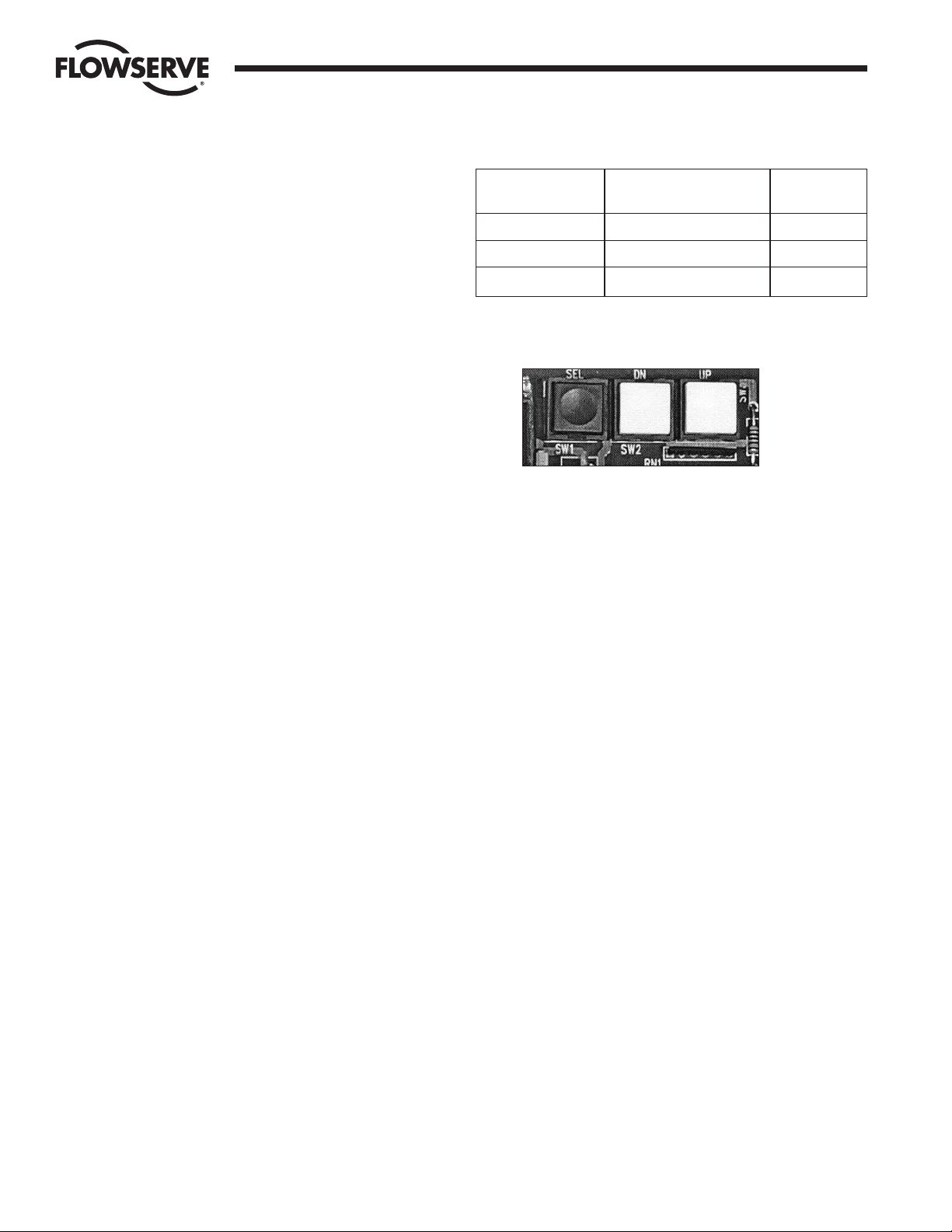
4.1 Programming Switches (Key Functions)
There are three switches (keys) on the positioner circuit board
which are labeled SEL (black) for select, DN (white) for down, and
UP (white) for up. These are the keys that are used to calibrate,
program and position the Digital Positioner Board locally.
The UP and the DN switches can be used to advance through the
menu until the desired parameter is reached. At this time, the
display will be flashing between the parameter name and its
current setting. Momentarily pressing the SEL switch will lock in
that parameter’s current setting and allow the user to change it. If
the display is alphabetic such as riSE or FALL for setpoint
direction, momentarily pressing the UP switch will cycle through
the setting options for that parameter. When the desired setting
option is reached, momentarily pressing the SEL switch will set
the parameter to that option and store it in nonvolatile memory. If
the display is numeric, momentarily pressing the SEL switch will
lock in the value with the left most digit flashing. Pressing the UP
switch will increment this digit. Pressing the DN switch will
advance the flashing digit to the next digit to the right. Therefore,
the UP switch is used to set the flashing digit to the desired value
while the DN switch is used to select the flashing digit. Once the
overall value is entered, momentarily press the SEL switch to
store the value in nonvolatile memory.
4.2 Limit Switch Adjustment and Calibration Procedures
4.2.1 Adjustment of Over-Travel Limit Switch
The Positioner has been shipped with a limit switch factorycalibrated to stop the actuator in the full CCW position
(approximately 92°). It is located in the actuator housing,
behind the flat cover. If it has been determined that the limit
switch requires adjustment, perform the adjustment as
follows:
Page 5

FCD WCAIM2048-01 Electri-SAFE DataFlo Digital Electronic Positioner 5
Flow Control
Worcester Controls
NOTE: Be very careful when adjusting the switch. It can be
damaged by the actuator switch probe if the switch is
adjusted (tightened) too far in toward the probe. If in doubt of
switch position, loosen (back out) the switch adjustment
screw to its loose limit before performing the following steps.
If not already done, remove the actuator and positioner
housing covers.
When power is first applied, the unit will be in the Run Mode.
The positioner display should be flashing between POS and a
number between 0 and 100.
On the positioner board, simultaneously press the SEL and
UP keys for three seconds to enter the Manual Mode. The
display should alternate between POS and 0.0.
Press and hold the UP key until the actuator goes full CCW
and stops moving. The actuator should be full CCW, and there
should be no motor noise.
If the motor continues to run, turn the limit switch adjustment
screw clockwise until the motor stops running. Turn the
adjustment screw clockwise an additional
1
/
4 turn to set the
switch. Verify the switch setting as follows:
Press the DN key to rotate the actuator shaft about 20
degrees CW.
Turn the limit switch adjusting screw counterclockwise
1
/
2
turn.
Press and hold the UP key until the actuator shaft rotates
to full CCW and stops moving.
If the actuator is not at full-open:
Press the DN key to rotate the actuator shaft about 20
degrees CW.
Turn the limit switch adjusting screw counterclockwise
1
/
2
turn.
Press and hold the UP key until the actuator shaft rotates
to full CCW and stops moving.
Repeat until the actuator is full-open and there is no
motor noise.
The actuator shaft must travel a couple of degrees beyond the
90 degree full CCW position for the positioner to control the
full range of operation. Place a straight edge along the flats
on the positioner shaft to verify that the actuator has gone
past the 90 degree position when stopped by the limit switch.
To return to the RUN mode, press and hold the SEL key for
three to five seconds.
4.2.2 Calibration Procedures for Positioner
NOTE: Also refer to section 4.6 for step-by-step procedures.
When power is first applied, the unit will be in the Run Mode.
The display should be flashing between POS and a number
between 0 and 100.
Simultaneously press and hold the SEL and DN switches
(keys) for three seconds to enter the calibration mode. When
first entering the Calibration Mode, CAL will be displayed for
two seconds and the security code will be checked. If the
required security code is not zero (“0000”), the display will
begin alternating between codE and 0000. Enter the security
code as described in paragraph 4.4.1 and per paragraph
4.3.6. If the required security code is zero, it will not need to
be entered by the user, i.e., it will be bypassed and the display
will automatically flash SEtL, and you can skip to paragraph b.
Note: If the security code is forgotten, the special number
4800 can be used to gain entry. However, this number will
now be the new security code and if another code number is
still desired, it will have to be reprogrammed.
If and after a security code has been entered, press and
release SEL to accept code. The display will now flash SEtL
and a value.
Simultaneously press and release the SEL and UP keys, then
adjust input signal to lower input value, e.g., 4 mA. Press and
release SEL to lock in value.
Press and release the DN key, the display will now flash SEtU
and a value. Simultaneously press and release SEL and UP,
then adjust input signal to higher input value, e.g., 20 mA .
Press and release SEL to lock in value.
Press and release DN, the display will now flash PoC and a
number between 0.0 and 5.0. Simultaneously press and
release SEL and UP. Rotate the actuator to the full CW
position by pressing and holding the DN key. Release the DN
key when full rotation has been achieved.
Important: Be careful not to go past the CW “0” degree
position. (Position a straight edge along the flats on the
positioner shaft to verify the shaft position). The display
should read between .200 and .400. If not: rotate the face gear
located on the positioner shaft (that drives the potentiometer)
until you read between .200 and .400. The gear is held in place
by means of a friction lock and a snap ring. No tools are
needed nor is it necessary to loosen or remove the snap rin
g
to move the gear. Steady gentle finger pressure will move the
gear to allow you to adjust the feedback potentiometer. Press
and release SEL to lock in the value.
Press and release the DN key, the display will now flash PoCC
and the feedback voltage value. Simultaneously press and
release SEL and UP. Adjust so shaft is full CCW using the UP
key (do not go past 90 degrees). Press and release SEL to
lock in value.
Press and release the DN key, the display will now flash Cyt
and a cycle time reading. Simultaneously press and release
the SEL and UP keys. At this time the actuator will perform
one cycle to measure its cycle time displaying PoC as the
actuator travels to the full CW position and PoCC for the
CCW position.
To return to the RUN mode, press and hold the SEL key for
three to five seconds.
Page 6
6 Electri-SAFE DataFlo Digital Electronic Positioner FCD WCAIM2048-01
Flow Control
Worcester Controls
4.3 General Description of Digital Positioner
The Digital Positioner is used for intelligent control and operation
of the Electri-SAFE Electro-Hydraulic Actuator.
4.3.1 Valve Position Setpoint Input
The valve position setpoint input signal is derived from either
an analog input signal or from a digital RS485 serial input.
4.3.2 Valve Position Feedback
Valve position feedback to the digital positioner board is from
the 1,000 ohm potentiometer geared to the actuator shaft.
4.3.3 Key Features of The Digital Positioner
Easy push-button calibration of the positioner
Programmable set point direction
Microprocessor-based positioner
Programmable split range
High resolution
Programmable deadband as well as auto adjust
Cycle count
Programmable operating parameters
Hi, Low, and Deviation alarms
Four programmable position response curves
Loss of signal position and time delay
Local and remote positioner operation
Loss-of-power position and time delay
Electronic travel limits
ASCII text area in EEPROM (420 + bytes)
4.3.4 Operating Modes
The four modes of operation are:
CALIBRATION (see part 4.2 and part 4.6)
PROGRAM (see part 4.4)
LOCAL (see part 4.5)
RUN (This is also the default mode, see part 4.7.)
4.3.5 Data Readout
A four-digit LCD mounted on the positioner board provides
local data readout. Each LCD segment is controllable, which
allows display of some letters in addition to all digits.
Parameters will be identified by names, not numbers.
Provisions for numerical values with decimal points will
be made.
4.3.6 Local Data Entry
Three push-button switches (as shown below) on the
positioner board are used for local data entry:
SEL Selects a parameter for editing or changes modes of
operation.
UP Increases selected value or selects next parameter.
Hereafter this switch will be called UP.
DN Decreases selected value or selects previous parameter.
Hereafter this switch will be called DOWN.
In the Program Mode of operation, data is edited by pressing
the SEL switch while the parameter name is alternating with
its value. The display will then be in the Fixed Mode where
one or more digits will flash.
With a single digit flashing, pressing the UP switch will
increase the digit value by 1, wrapping from 9 to 0. Pressing
the DOWN switch will cause the next digit to blink and allow it
to be edited. Pressing the SEL switch will store the value in
non-volatile memory, discontinue editing, and return the
display to the Toggle Mode.
Note: Displayed data cannot be edited in the Run Mode.
Pressing the SEL switch in that mode causes the display to
stop alternating and only the parameter value is displayed.
4.3.7 Display Modes
The display has two modes of operation: Toggle Mode and
Fixed Mode.
In Toggle Mode (default), the display will alternate between a
parameter name and its value. In Fixed Mode (press SEL
switch), only the value appears on the display. If a parameter
is being edited, one or more digits are blinking as the value of
the parameter is being displayed.
Key combination New mode
while in run mode New mode entry display
SEL Program Mode Prog
SEL + UP Manual Setpoint Mode Loc
SEL + DN Calibration Mode CAL
Page 7

FCD WCAIM2048-01 Electri-SAFE DataFlo Digital Electronic Positioner 7
Flow Control
Worcester Controls
4.4 Program Mode (Data Entry Parameters)
The table below shows all programmable parameters, their display name and data range.
Parameter Minimum Maximum
Name Display Numeric Value Numeric Value Pick List Values Description Notes
CodE 0000 9999 Security code
Addr 1 255 Communications address
Ocur 4-20, 0-20 Optional current output module range
Sdir riSE, FALL Setpoint direction
SPrS 0.0 % 99.9 % Split range start point.
SPrE 0.1 % 100.0 % Split range end point.
OPEn 0 sec 200 sec Ramp open (CCW) time. 1
CLOS 0 sec 200 sec Ramp close (CW) time. 1
SFc Lin, FrE1, FrE2, Setpoint function (linear or curve select)
FrE3, FrE4
dEbA 0.3 % 10.0 % Auto Positioning deadband 2
SPOS 0.0 % 100.0 % HOLd Loss of setpoint signal position
SPt 0 sec 9999 sec Loss of setpoint dwell time
PPOS 0.0 % 100.0 % HOLd Power-on position
PPt 0 sec 9999 sec Power-on position dwell time
yA 0.0 % 100.0 % Positioner lower (CW) rotational limit 3
yE 0.0 % 100.0 % Positioner upper (CCW) rotational limit 3
yCLS yES, no Tight valve shutoff operation. 4
yOPn yES, no Full open valve operation. 5
bAUd 1200, 2400, 4800, Communications rate.
9600, 19200, 38400
CyS Valve total travel time
(from full CW to full CCW and back). 6
CyCn Total number of valve cycles.
AdE Deviation alarm time. 6
AHi 0.0 % 100.0 % Valve high (CCW) position alarm.
ALo 0.0 % 100.0 % Valve low (CW) position alarm.
SLxx 0.0 % 100.0 % Free curve vertices (see section 4.4.10)
PrSt yES, no Option to set all parameters to their
default values (see section 4.4.17).
Page 8

8 Electri-SAFE DataFlo Digital Electronic Positioner FCD WCAIM2048-01
Flow Control
Worcester Controls
The Program Mode is entered from the Run Mode by
pressing the on-board SEL switch for three seconds.
When first entering the Program Mode, Prog will be displayed
for two seconds and the security code will be checked. If the
required security code is not zero, the display will begin
alternating between CodE and 0000. Enter the security code
as described in paragraph 4.4.1. If the required security code
is zero (“0000”) it will not need to be entered by the user, i.e.,
it will be bypassed.
After any required security code is correctly entered, a menu
allows the user to select individual parameters they wish to
program.
For all parameters in the table on previous page, the display
will be in Toggle Mode alternating between showing the
parameter name for one second then its value for one second.
Pressing the UP or DOWN switches in the Toggle Mode will
display the next or previous parameter (respectively).
Pressing the SEL switch while in the Toggle Mode will enter
the Fixed Mode of display where the value can be altered.
As explained in paragraph 4.3.6, values are edited by pressing
the UP or DOWN switches (UP to increment digit and DOWN
to advance to the next digit) until the desired value is
obtained. Pressing the SEL switch while editing will record
the new value and return the display to the Toggle Mode.
If an invalid value is entered for a parameter, the display will
flash an error message until acknowledged by the user. The
user can acknowledge an error by pressing the SEL switch.
4.4.1 Security Code Screens
The display will alternately display CodE and 0000
The correct security code number must be entered to gain
access to Program and Calibration Modes. Once in the
Program Mode, the security code can be reprogrammed.
Legal security code values are 0000 to 9999. Note that when
the security code of 0000 is used, the security option will be
bypassed. With a code of 0000 the user is not required to enter
the code to gain access to modes that use the security code.
If the security code is forgotten, the special number 4800 can
be used to gain entry to modes that require a security code.
However, this number will now be the new security code and
if another code number is still desired, it will have to be
reprogrammed.
4.4.2 Unit Address Screen
The display will alternately display Addr and the communications address, which is factory set at 1 on new units.
CAUTION: Do not install two units with the same address on
the same RS485 bus.
To edit the value, use the UP or DOWN switches to select a
value from 1 through 255.
4.4.3 Output Current Range
The display will alternately display Ocur and either 4-20
or 0-20.
Edit the value and use the UP or DOWN switches to select
0-20 or 4-20.
4-20 selects a 4-20 mA output current range.
0-20 selects a 0-20 mA output current range.
A voltage output can be achieved by connecting a resistor
across the current output.
The output current feedback is linear.
4.4.4 Analog Setpoint (Input) Range
The analog setpoint (input) signal range is fixed.
Notes Description
1 If a time of “0” is used or a time is entered that is less than the travel time, the rate of response to a step change in the
input signal we be as fast as the actuator can operate.
2 The deadband is used to prevent oscillations about a setpoint because of small fluctuations in either the setpoint signal or
the position feedback signal. The deadband represents a plus and minus percentage of the full range of either the input
signal or the feedback signal. Deadband can be set to a fixed value or it can be set to Auto. See paragraph 4.4.11 for a
discussion of deadband.
3 In normal operation, the valve will operate in the yA to yE limits. yA must be less than yE. The yA value is the most CW
position and the yE value is the most CCW position the valve will be able to travel.
4 Tight valve shutoff specifies if the valve should be closed completely when the signal is between 4.1 and 4.2 mA, regardless
of the yA setting. So if yCLS is yES and yA is at 20.0 % the valve will close completely (full CW) when the setpoint is between
4.1 mA and 4.2 mA even though 20% was the lower limit.
5 Full-open valve operation specifies if the valve should be opened completely when the signal is between 19.8 and 19.9 mA,
regardless of the yE setting. So if yOPn is yES and yE is at 70.0% the valve will open completely (full CCW) when the
setpoint is between 19.8 mA and 19.9 mA even though 70% was the upper limit.
6 This parameter is read-only and cannot be modified by editing.
Page 9

FCD WCAIM2048-01 Electri-SAFE DataFlo Digital Electronic Positioner 9
Flow Control
Worcester Controls
4.4.5 Setpoint Direction (Rise/Fall)
The display will alternately display Sdir and either riSE or
FALL.
Use the UP or DOWN switches to select riSE or FALL.
riSE selects direct acting positioner control where the actuator
rotates in the CCW direction as the setpoint signal increases.
The valve is full CW at the minimum setpoint signal value.
FALL selects reverse acting positioner control where the
actuator rotates in the CCW direction as the setpoint signal
decreases. The valve is full CCW at the minimum setpoint
signal value and full CW at the maximum setpoint signal value.
4.4.6 Setpoint Split Range START Selection
The display will alternately display SPrS and its value.
For a direct-acting positioner, SPrS specifies the START of the
split range input signal for the full CW actuator position, and
must be less than SPrE. For a reverse-acting positioner, SPrS
specifies the START of the split range input signal for the full
CCW actuator position, and must be less than SPrE.
The setting can be anywhere from 0.0 to 99.9% of the input
signal range in 0.1% increments.
Split ranging is useful when more than one valve is used in a
control system. As an example, one actuator can be calibrated
to open for an input signal between 4-12 mA and another to
open for an input signal between 12 and 20 mA.
4.4.7 Setpoint Split Range END Selection
The display will alternately display SPrE and its value.
For a direct-acting positioner, SPrE specifies the END of the
split range input signal for the full CCW actuator position, and
must be greater than SPrS. For a reverse-acting positioner,
SPrE specifies the END of the split range input signal for the
full CW actuator position, and must be less than SPrS.
The setting can be anywhere from 0.1 to 100.0% of the input
signal range in 0.1% increments.
4.4.8 Setpoint Ramp-Time to Open
The display alternately displays OPEn and the selected time to
open.
Times from 0 to 200 seconds can be selected as the time for
the actuator to travel from the full-closed (CW) to the fullopen (CCW) position.
If “0” (or a time less than the CCW travel time) is selected,
the rate of response to a step change in the input signal will
be as fast as the valve actuator can operate. The slowest time
to open is 200 seconds.
4.4.9 Setpoint Ramp-Time to Close
The display alternately displays CLOS and the selected time to
close.
Times from 0 to 200 seconds can be selected as the time for
the actuator to travel from the full-open (CCW) to the fullclosed (CW) position.
If “0” (or a time less than the CW travel time) is selected, the
rate of response to a step change in the input signal will be as
fast as the valve actuator can operate. The slowest time to
close that can be selected is 200 seconds.
4.4.10 Setpoint Curve Function
The positioner translates the setpoint input using a table of
values. The positioner contains a linear table and four 21point curves called free curves. By default, the linear
translation table is used (SFn is set to Lin). The four free
curve tables can be edited to allow different translation curves
to be used. By default, free curve #1 (FrE1) is preset to a 1:25
equal percentage response curve, free curve #2 (FrE2) is
preset to 1:50 equal percentage response curve, and free
curves #3 and #4 (FrE3 and FrE4) are each preset to a linear
response curve. All four free curves can be modified. The
table on the next page shows all the tables and the default
free curve values. These values are loaded any time the
parameters are defaulted with the PrSt parameter.
NOTE: Definition of equal percentage: for equal increments of
valve rotation, the C
v
increases by a given percentage over
what it was at the previous setpoint.
The display will alternately display SFc and either Lin or FrE1,
FrE2, FrE3, or FrE4.
This function tells the positioner the desired shaft positioning
characteristic with respect to input signal.
Lin causes the shaft position to vary in a linear fashion as
the input signal changes (i.e., if the signal is at 50 percent,
the shaft position will be at 50 percent of the selected
operating range).
The FrE1-FrE4 curves allow 21 setpoint vertices to be set. In
this way, a custom shaft positioning characteristic can be
entered. There is a vertices set (data point) at 4 mA and then
every 0.8 mA up to and including 20 mA. The vertices are
displayed as SL 0 to SL 20 and will only be displayed when
one of the FrE1-FrE4 curves is chosen as the setting. The SL
parameters can be found in the menu between the PrSt
parameter and the CodE parameter. Use the UP and DOWN
switches to select and change the vertices settings.
Page 10

10 Electri-SAFE DataFlo Digital Electronic Positioner FCD WCAIM2048-01
Flow Control
Worcester Controls
4.4.11 Positioner Deadband
The display will alternately display dEbA and the deadband
value.
The deadband is used to prevent oscillations about a setpoint
because of small fluctuations in either the setpoint signal or
the position feedback signal. The deadband represents a plus
and minus percentage of the full range of either the input
signal or the feedback signal. Fixed deadband values can be
selected from 0.1 to 10.0 (percent) of range. When the DOWN
switch is pressed when the right most digit is selected, the
display will show Auto. Pressing SEL while on that screen will
select Auto deadband.
A deadband setting of Auto will allow constant automatic
adjustment of the deadband in an adaptive fashion as required
for best performance. This is the recommended setting. The
lower Auto default value is .5 but this can be changed with
the manual setting. Whatever value has been set for the
manual deadband setting, becomes the lower limit for the
Auto deadband mode.
4.4.12 Loss-of-Signal Position and Delay Time
The display will alternately display SPOS and the position the
valve will move to if there is a loss of signal. A loss-of-signal
condition occurs in either of two situations: 1) When the
positioner is in analog position control and the input signal is
less than 2 mA; or 2) When the positioner is controlled by the
serial data link (digital control) and no signal has been
received within the SPt time period.
When a loss of signal occurs in the analog control mode, the
positioner will immediately go to the SPOS position. A HOld
option specifies the positioner is to hold its current position.
The positioner will hold the SPOS position until a valid analog
input signal is present for the SPt delay period. If the SPt
parameter is set to 0 seconds, restoration of the signal will
cause the positioner to work as normal with no time delay.
A loss of signal in PC CMD control mode means the
positioner has not received a valid command within the SPt
time period. In that case, the positioner will immediately go to
the SPOS position. A HOld option specifies the positioner is
to hold its current position. The positioner will hold the SPOS
position until a valid digital position command is received.
The display will alternately display SPt and the delay time (in
seconds). The time range is 0 to 9999 seconds. A time of 0 in
analog control mode disables the loss-of-signal option. A time
of 0 in digital control mode effectively disables the loss-ofsignal option by allowing an infinite time between received
commands. In digital-control mode, non-zero SPt time values
less than three seconds will use three seconds as the delay.
4.4.13 Power-On Position and Delay Time
When power is first applied to the positioner and the unit is in
analog signal control mode, it will go to the position specified
by the PPOS parameter for a time specified by the PPt
parameter. During that time, any input signal is ignored.
If the unit is in PC Cmd control mode and there is a valid PC
signal, the unit will respond to the signal immediately,
otherwise, it will go to the power on position for the PPt time
and then go to the SPOS position for the SPt time.
The display will alternately display PPOS and the position (in
percent) the valve will move to when power is first applied or
when power is restored. The actuator will hold that position
for the time specified in the next step. The position range is
0.0 to 100.0% and HOLd. A HOLd option specifies the
positioner is to hold the last position (i.e., the actuator will
not move).
The display will alternately display PPt and the time (in
seconds) that the PPOS position will be held. During that
time, the positioner will ignore any input signal and will hold
the PPOS position. The time range is 0 to 9999 seconds. A
time of 0 disables this option such that the positioner will
immediately respond to the input signal when power is first
applied or restored.
Free Free
Linear Curve #1 Curve #2 Free Free
Curve 1:25 1:50 Curve #3 Curve #4
Parameter (Lin) (FrE1) (FrE2) (FrE3) (FrE4)
SL 0 0.0 % 0.0 % 0.0 % 0.0 % 0.0 %
SL 1 5.0 % 0.8 % 0.3 % 5.0 % 5.0 %
SL 2 10.0 % 2.1 % 0.8 % 10.0 % 10.0 %
SL 3 15.0 % 3.2 % 1.5 % 15.0 % 15.0 %
SL 4 20.0 % 4.9 % 2.6 % 20.0 % 20.0 %
SL 5 25.0 % 6.5 % 3.7 % 25.0 % 25.0 %
SL 6 30.0 % 8.4 % 5.0 % 30.0 % 30.0 %
SL 7 35.0 % 10.7 % 6.6 % 35.0 % 35.0 %
SL 8 40.0 % 13.2 % 8.4 % 40.0 % 40.0 %
SL 9 45.0 % 15.7 % 10.9 % 45.0 % 45.0 %
SL10 50.0 % 18.7 % 13.5 % 50.0 % 50.0 %
SL11 55.0 % 22.6 % 16.5 % 55.0 % 55.0 %
SL12 60.0 % 27.2 % 20.3 % 60.0 % 60.0 %
SL13 65.0 % 33.4 % 25.0 % 65.0 % 65.0 %
SL14 70.0 % 40.0 % 31.1 % 70.0 % 70.0 %
SL15 75.0 % 46.0 % 36.8 % 75.0 % 75.0 %
SL16 80.0 % 53.8 % 45.4 % 80.0 % 80.0 %
SL17 85.0 % 63.2 % 54.4 % 85.0 % 85.0 %
SL18 90.0 % 73.7 % 67.5 % 90.0 % 90.0 %
SL19 95.0 % 86.2 % 85.0 % 95.0 % 95.0 %
SL20 100.0 % 100.0 % 100.0 % 100.0 % 100.0 %
Page 11

FCD WCAIM2048-01 Electri-SAFE DataFlo Digital Electronic Positioner 11
Flow Control
Worcester Controls
4.4.14 Electronic Positioner Rotation Limits (Electronic travel stops)
The display will alternately display yA and its position value.
yA is the electronic lower rotation limit for shaft position at
the start of the signal range. It can be set to a value from 0.0
to 100.0 in increments of 0.1 percent.
Press the UP switch to advance to the yE parameter screen.
The display will alternately display yE and its position value.
yE is the electronic upper rotation limit for shaft position at
the end of the signal range. It can be set to a value from 0.0
to 100.0 in increments of 0.1 percent.
If yA were set at 20.0 then the actuator shaft would never
rotate further CW than 20 percent open. If yE is set to 70
percent then the actuator shaft would never rotate further
CCW than 70 percent open. These electronic limits restrict the
range of actuator shaft rotation.
yA must always be less than or equal to yE. yE must always
be greater than or equal to yA.
4.4.15 Tight Valve Shutoff
The display will alternately display yCLS and its setting.
yCLS is how we specify whether tight valve shutoff is desired
when the input signal reaches the low end of its range. It is
significant when the yA function is set to a value other than
0.0 percent. The two choices are yES and no. As an example,
if the actuator/valve is controlling fuel flow to a burner, yA
might be set to 30 percent as a low-fire position, but between
4.1 and 4.2 mA the valve would fully close if yCLS is set to
yES to allow maintenance to be performed on the burner.
4.4.16 Full-Open Operation of Valve with Open Travel Limit Set
The display will alternately display yOPn and its setting.
yOPn is how we specify whether the valve will fully open
when the input signal reaches the upper end of its range. It is
significant when the yE function is set to a value other than
100.0 percent. The two choices are yES and no. As an
example, if yE is set at 70 percent and yOPn is set to yES,
then the actuator/valve would be 70 percent open at 19.8 mA,
but would open fully when the signal is increased to 19.9 mA.
4.4.17 Restore Factory Default Values
The display will alternately display PrSt and no.
If yES is selected instead of no then the factory default values
for all parameters will be selected. This flag is not a parameter
but must be edited the same way to select yES. This is a
momentary function and values can be altered after the default
values have been selected. After the factory default values have
been reloaded, the display will once again display no.
See Part 4.8 for a list of the default values.
4.4.18 Run Time Cycles for Maintenance
The display will alternately display CyS and the total number
of seconds for the valve to travel from full counterclockwise
to full clockwise then back to full counterclockwise. This
cycle time is measured in the cycle time calibration routine
which is performed after the feedback potentiometer
calibration routine.
The microprocessor converts run time into cycles.
The next screen displays accumulated cycles CyCn. The
number shown represents thousands of cycles. The display
can show up to 9.999 million cycles. Obviously at higher
resolutions, less resolution is available on the display. Only
whole cycles are displayed.
With CyCn displayed, the user can press the SEL switch and
the total will begin flashing. At that point, holding down the
DOWN switch for four seconds will clear the total.
Because the life of EEPROM is based on the number of write
operations, only every 100 cycles will cause the total to be
written to the non-volatile memory.
4.4.19 Alarm Functions
The DEVIATION alarm becomes active if the valve does not
move to the desired position within a certain time period. The
time period is 10 seconds plus either the ramp time for the
direction in which the actuator is moving, or the open/close
time from calibration, whichever is greater.
A means to set UPPER and LOWER rotation alarm limits on
the actuator/valve shaft position is provided. An alarm shall
occur if the positioner rotates beyond either the upper or
lower set limit. The range of rotation limits is from 0 to 100%.
An example of typical alarm limits would be 20% for LOWER
and 80% for UPPER.
An opto isolated open collector/open emitter alarm output will
be on whenever any alarm condition exists.
NOTE: For wiring of alarm outputs refer to diagram at right.
Two alarm parameters will be programmable:
Ahi: 0.0 to 100.0% For the upper rotation alarm.
Alo: 0.0 to 100.0% For the lower rotation alarm.
Load Specs. for Alarm Output:
Maximum Collector/Emitter Voltage is 50 Volts DC
Maximum Collector/Emitter Current is 100 mA
The AdE value is also shown with the programmable
parameters to show the deviation alarm time. This value
cannot be edited.
Page 12

12 Electri-SAFE DataFlo Digital Electronic Positioner FCD WCAIM2048-01
Flow Control
Worcester Controls
4.5 Local Mode
Local Mode is provided to allow manual control of the positioner.
Local Mode is entered from the Run Mode by holding down the
SEL and UP switches simultaneously for three seconds. From the
Local Mode, pressing and holding the SEL switch for two seconds
will return to the Run Mode.
In the Local Mode, the display will show POS alternating with the
position. Pressing the SEL switch will stop the alternating.
Press either the UP switch to travel CCW or the DOWN switch to
travel CW.
4.6 Feedback Calibration Routine and Cycle Time Measurement
The Calibration Mode provides a way to properly calibrate signals
used by the positioner. Periodic calibration is recommended to
maintain accurate positioning. This mode is entered from the
Run Mode by simultaneously holding down the SEL and DOWN
switches for three seconds. From the Calibration Mode, pressing
and holding the SEL switch for two seconds will return to the
Run Mode.
When first entering the Calibration Mode, CAL, will be displayed
for two seconds and the security code will be checked. If the
required security code is not zero (“0000”) the display will begin
alternating between CodE and 0000. Enter the security code as
described earlier in paragraph 4.4.1 and 4.3.6. If the required
security code is zero, it will not be required to be entered by the
user (i.e., it will be bypassed).
After any required security code is correctly entered, a menu
allows the user to select individual calibration procedures they
wish to perform.
The user is presented with the first of several calibration
parameters. Calibration is performed in a manner similar to
parameter editing in the Program Mode. A parameter is shown
alternating with its current value. Pressing the DOWN switch will
select the next calibration parameter. To perform the calibration
procedure for a displayed parameter, simultaneously press the
SEL and UP switches. When calibration of the selected item is
completed, press the SEL switch to return to the menu.
In the table below, calibration names are shown as they appear on
the display with their definition. The table also shows the order of
the procedures.
Parameter
Name Description
SEtL Set point range lower limit signal value.
SEtU Set point range upper limit signal value.
PoC Shaft position feedback value in clockwise position.
PoCC Shaft position feedback value in counterclockwise
position.
Cyt Cycle time measurement
A. Input (setpoint) Signal Calibration
1. Use the DOWN switch to go to SEtL.
2. The display will alternate between SEtL and the voltage
resulting from the input current signal.
3. To edit, simultaneously Press and release SEL and UP
switches and then: Adjust the signal source to produce
the lower input reading, e.g., a 4 mA signal. The voltage
reading should be less than 1.0 volts. Press the SEL
switch to lock in the full CW reading. Control returns to
the Calibration Menu.
4. Use the DOWN switch to go to SEtU.
5. The display will alternate between SEtU and the voltage
resulting from the current signal.
6. To edit, simultaneously press and release SEL and UP
switches and then: Adjust the signal source to produce
the higher input reading, e.g., a 20 mA signal. Press the
SEL switch to lock in the full CCW input reading. Control
returns to the Calibration Menu.
B. Position Endpoint Calibration
1. Use the DOWN switch to go to PoC.
2. The display will alternate between PoC and the feedback
voltage value.
3. To edit, simultaneously Press and release SEL and UP
switches and then: Use either the UP or DOWN switches
to manually rotate the actuator to its full CW position.
Important: Be careful not to go past the CW “0” degree
position. (Position a straight edge along the flats on the
positioner shaft to verify the shaft position). The display
should read between .200 and .400. If not: rotate the face
gear located on the positioner shaft (that drives the
potentiometer) until you read between .200 and .400. The
gear is held in place by means of a friction fit and snap
ring. No tools are needed nor is it necessary to loosen or
remove the snap ring to move the gear. Steady gentle
finger pressure w
ill move the gear to allow you to adjust
the feedback potentiometer. Press and release SEL to lock
in value.
4. Use the DOWN switch to go to PoCC.
5. The display will alternate between PoCC and the feedback
voltage value.
6. To edit, simultaneously press and release SEL and UP
switches and then: Use the UP switch to manually rotate
the actuator to the CCW 90° position. (Do not go past
90°. Place a ruler on the positioner shaft flat for
indication.) If the shaft rotates past 90°, use the DOWN
switch to bring the shaft back to the 90° position. Press
the SEL switch to lock in the 90° feedback reading.
Control returns to the Calibration menu.
Page 13

FCD WCAIM2048-01 Electri-SAFE DataFlo Digital Electronic Positioner 13
Flow Control
Worcester Controls
C. Cycle Time Calibration
NOTE: THIS PROCEDURE SHOULD ONLY BE PERFORMED
AFTER A VALID POSITION ENDPOINT CALIBRATION
PROCEDURE HAS BEEN COMPLETED.
1. Use the DOWN switch to go to Cyt.
2. The display will alternate between Cyt and a cycle time
reading.
3. Simultaneously press and release SEL and UP switches.
If this is selected, the actuator will first go to the full CCW
position (if is not already there).
The display will than show PoC and the actuator will travel to
the full CW (closed) position and record the travel time. At
that point, the CW time measurement will begin.
The display will then show PoCC and the actuator will travel
the full CCW (open) position and record the travel time. At
that point, the cycle time calibration is complete and control
returns to the calibration menu.
4.7 Run Mode
The valve actuator run mode display depends upon how the
digital positioner board has been programmed.
There are seven Run Mode display screens: POS, SEt, CyCn,
dbnd, CyC, CyCC, and ALr. The UP and DOWN switches are used
to sequence to the next or previous screen when the parameter
name screen is displayed.
For all screens described below, the display will alternate between
the name and its value. Pressing the SEL switch will lock the
value on the screen.
4.7.1 Valve Position Screen
The display alternately displays POS and xx.x, the valve
position in percent.
4.7.2 Input Setpoint
The display alternately displays SEt and xx.x in percent.
4.7.3 Cycle Count
The display alternately displays CyCn and the total run mode
cycles.
4.7.4 Deadband Readout
The display alternates between dbnd and the current
deadband value (even when Auto dbnd is selected).
4.7.5 CW and CCW Travel Time Readout
The display alternates between CyC and the calibrated time it
took (in seconds) to go from the full CCW position to the full
CW position.
Pressing the SEL key then shows the CCW time. The display
alternates between CyCC and the calibrated time it took (in
seconds) to go from the full CW position to the full CCW
position. This is useful for comparing calibrated times with
current times.
4.7.6 Alarm Status Readout
The display alternates between Alr and the current alarm
condition. A high limit alarm condition will display Hi; a low
alarm condition will display Lo; a deviation alarm condition
will display dE. Since only one alarm condition can be shown
on the display, the deviation alarm takes priority over the
other alarms. When the deviation alarm is no longer active,
the other alarms will be shown as described above.
4.7.7 Changing Operating Modes
In the Run Mode, holding down the SEL switch alone for
three seconds will switch to the Program Mode. In the Run
Mode, holding down the SEL and DOWN switches
simultaneously for three seconds will enter the Calibration
Mode. Holding down the SEL and UP switches simultaneously
for three seconds will enter the Local Mode.
When the Program Mode is entered, Prog will briefly be
displayed before the sequence described in part 4.4 begins.
Pressing and holding the SEL switch in the Program Mode
will exit and return to the Run Mode.
When the Local Mode is entered, Loc will briefly be displayed
before the sequence described in part 4.5 begins. Pressing
and holding the SEL switch in the Local Mode will exit and
return to the Run Mode.
When the Calibration Mode is entered, CAL will briefly be
displayed before the sequence described in part 4.6 begins.
Pressing and holding the SEL switch in the Calibration Mode
will exit and return to the Run Mode.
When the Run Mode is reentered, run will be displayed briefly.
Run
Mode
Display Units
Item Definition of Data
POS Valve Position Percent
SEt Setpoint Position Percent
CyCn Count of completed cycles Cycles
dband Operating Deadband Percent
CyC Clockwise valve travel time from Calibration Seconds
CyCC Counterclockwise travel time from Calibration Seconds
ALr Alarm conditions that are active
as shown below:
De Deviation (excessive valve
travel time) alarm.
Hi Valve position greater than
high alarm point.
Lo Valve position less than
low alarm point.
NoNe No alarms active.
Page 14

14 Electri-SAFE DataFlo Digital Electronic Positioner FCD WCAIM2048-01
Flow Control
Worcester Controls
4.8 Default Values (factory installed)
When default parameters are loaded in Program Mode, they are
set as follows: See paragraph 4.4.17 for the procedure to set
default values.
To restore all the parameters to the factory default settings as listed
here, advance to the PrSt parameter, momentarily press the SEL
switch, and then momentarily press the UP switch. The display will
show yES for several seconds and then again begin flashing
between PrSt and no. The factory defaults are now installed.
4.9 RS-485 Communications
NOTE: The positioner must be in the RUN MODE for communication
between the positioner and computer.
The Digital Positioner Board may be connected to a computer or
PLC via an RS-485 two-wire serial bus. Unless the computer has
an RS-485 port built in, it will be necessary to use an RS-232 to
RS-485 converter on one of the computers serial ports. If there is
more than one positioner on the serial bus, all positioner boards
except for the last one on the bus must have the 120 ohm
terminator resistor removed (see figure 1 in appendix for resistor
location). The terminator resistor is in socket pins. The
positioners should be connected to the RS-485 bus in a daisy
chain fashion. CAUTION: Do not connect two units with the same
address to the same RS-485 bus.
4.9.1 See the Worcester/McCANNA Packet Communications
specification for the communications protocol information. It
is on the software floppy diskette in the form of a txt file in
the commspec directory and is called commspec.txt.
4.9.2 The RS-485 Converter must be connected directly to
terminal strip TB1 of positioner board: terminals (1) positive;
(2) negative and the shield connected to terminal (3).
4.9.3 A floppy disk is provided with the software that is to be
installed on a computer which will allow communication with
the positioner. There is one executable program on the floppy,
ICP1.EXE, as well as several support files. The program may
be run from the floppy. Flowserve strongly recommends that
one or two backups be made of the software diskette before
using it. Write protect the disks, or copy the software to the
computer’s hard drive (create an ICP directory and then copy
all the files to that directory).
4.9.4 Setting Up The Communication Serial Port
NOTE: THE POSITIONER HAS BEEN FACTORY-SET AT A BAUD
RATE OF 38,400 bps.
The baud rate range is 1,200 bps to 38,400 bps. The baud
rate can be reset by reprogramming the positioner using the
manual keys on the positioner board (see Part 4.5) but then
will require resetting the baud rate in the communication
software. (Baud rate as shown on the positioner board display
must be the same as set up in the communication software.)
Parameter
Name Factory
Parameter Display Default
Security code CodE unaffected
Communications address Addr unaffected
Optional current output module range Ocur 4-20 mA
Setpoint direction Sdir RISE
Split range start point SPrS 0.0 %
Split range end point SPrE 100.0 %
Ramp open (CCW) time OPEn 0 sec
(ASAP)
Ramp close (CW) time CLOS 0 sec
(ASAP)
Setpoint function SFc LINEAR
Positioning deadband dEbA 0.5 %
Loss of setpoint signal position SPOS 0.0 %
Loss of setpoint dwell time SPt 0 sec
Power-on position PPOS 0.0 %
Power-on position dwell time PPt 0 sec
Positioner lower rotational limit yA 0.0 %
Positioner upper rotational limit yE 100.0 %
Tight valve shut off operation yCLS NO
Full open valve operation yOPn NO
Communications rate bAUd 38400
Valve total travel time CyS Unaffected
Total number of valve cycles CyCn Unaffected
Deviation alarm time AdE Unaffected
Valve high (CCW) position alarm. AHi 100.0 %
Valve low (CW) position alarm. ALo 0.0 %
Model 485F9 (9pin)
or 485F (25 pin)
485 Converter
1.5K
1.5K
PWR SUPPLY +9VDC
PWR SUPPLY GND
TB1
TB1
2
1
Receive -
Receive +
(SHIELD)
(NO CONNECTION)
EN\
GND
TX
TX\
RX\
RX
GND
C
TB1
3
Sample RS-485
Connection
Positioner Board
ICS
VD
Page 15

FCD WCAIM2048-01 Electri-SAFE DataFlo Digital Electronic Positioner 15
Flow Control
Worcester Controls
The communication software has been factory-set to default
to communication port-1 “com-1” but can be reset to
communication ports 2, 3, or 4 if required, as shown using
Windows 98 in the following steps. The software baud rate
has been factory set to 38,400 bps to agree with the
positioner factory setting and can also be changed as follows.
After creating a directory and installing the software in your
computer, perform the following:
a) In Explorer, select the Electri-Safe communications
software folder and open it.
b) Select the “ICP.EXE” file, right mouse click and select
“create shortcut” and drag the shortcut to your desktop.
c) Right mouse click on the communication Icon shortcut on
your desktop and select properties.
d) On the properties screen select program and the
“command line” should show the path ending in “EXE”.
e) To change the default baud rate and communication
path—as an example—enter the following.
Change baud rate to 19,200 bps.
Change communication port to port-2.
After “EXE” in the command line, insert a space and enter
19200, insert another space and enter 2.
The command line path should look like the following,
using your directory name.
C:\ directory \ ICP.EXE 19200 2
Note: The baud rate in the positioner has to match the
baud rate set in the software command line.
4.9.5 Monitor Display
Once the program has been started, the following screen will
appear (see Figure 1 on following page):
The program will start up looking for address 1. If that unit
exists, communications are established. Otherwise, to
establish communications with the positioner, tap the space
bar. The cursor to the right of the arrow next to the address
parameter will begin flashing. Type in the positioner address
and then hit the enter key (factory default is 1). The words
Reading data… will appear to the right of the arrow. In about
two seconds the screen will fill with the positioner data. The
arrow just to the left of the Status area indicates whether the
positioner is under control of the analog signal or under the
control of the computer (PC). The F4 key toggles between
computer and analog control of the positioner.
The PC Cmd value in the Status area is the position output of
the computer. This value can be changed with the left and
right cursor keys but will only control position when the F4
key toggles to PC Cmd. Position can also be changed by
pressing F12, entering the desired position on the numeric
keypad and then pressing the enter key.
Input is the value of the analog signal being received by the
positioner board and controls position only when the F4 key
toggles to Input.
Output is the value of the 4-20 mA output signal for shaft
position feedback (when this option is installed). Shaft Pos is
the actual readout of the actuator shaft position in percent of
shaft travel.
DB Run is the current setting for positioner deadband. When
shaft motion stops, shaft position should always be within the
deadband of the position command signal.
The Alarms are Over, Under, and Dev (Deviate). The area
immediately under one of these alarms will light up if that
alarm condition exists. The alarms are defined as follows:
Over – Shaft position is greater than the value set in the Overtravel Alarm.
Under – Shaft position is less than the value set in the Undertravel Alarm.
Dev – Shaft has not reached position called for by signal
within the time specified by Deviation Alarm.
The Calibration Data is a listing of the stroke times measured
during calibration.
The listings under Ver x.xx are the keys required to control the
screen and the positioner.
F2 – Load a file of all parameters including curve data from
the hard drive and download it to the positioner (about 40
seconds).
F3 – Save the data in the positioner to a file on the hard drive
(about 20 seconds).
F4 – Toggle control of the positioner between the analog
signal and the computer.
F9 – Enter the positioner response curve edit screen.
F10 – Enter the positioner ASCII EEPROM edit screen.
(Customer information for this unit)
F12 – Enter desired position on numeric keypad then press
enter.
[Right Arrow] – Increment the PC Cmd position output signal.
[Left Arrow] – Decrement the PC Cmd position output signal.
Alt-x – Exit the ICP program and return to DOS or Windows.
Page 16

16 Electri-SAFE DataFlo Digital Electronic Positioner FCD WCAIM2048-01
Flow Control
Worcester Controls
Figure 1: The following screen appears when the ICP program is first started:
The following screen appears after the Positioner Default Data is Loaded: (Some values may vary)
NOTE: If you are not using the RS-485 converter that is shown above, then refer to the documentation that came with your converter for proper
connections.
Page 17

FCD WCAIM2048-01 Electri-SAFE DataFlo Digital Electronic Positioner 17
Flow Control
Worcester Controls
5.0 Technical Data
5.1 Allowable Supply Voltage Range
120 VAC ±10% 50/60 Hz
Power Consumption
3 Watts
5.2 Input Circuit Specifications
Maximum Tolerated Noise Level at Maximum Positioner
Resolution/Sensitivity: Approx. 3.5 mV (16 microamps)
Resistance Input
DP72-1K Nominal 1000 Ohms
DP72-13 Nominal 135 Ohms
Current Input
DP72-1 1 to 5 milliamps
DP72-4 4 to 20 milliamps
DP72-10 10 to 50 milliamps
Voltage Input
DP72-5V 0 to 5 VDC
DP72-XV 0 to 10 VDC
5.3 Output Circuits Specifications
5.3.1 Motor Driver Circuitry Specifications
Maximum Normal Starting or In-Rush Current
10 amps for 1 second
Maximum Stall Current
8 amps for 1 minute
Maximum Running Current
5 amps (resistive load, 90% duty cycle)
Maximum Running Current
3 amps (inductive load, 90% duty cycle)
Maximum Peak Voltage at Load Circuit
800 VAC
5.3.2 Position Feedback – Current Output
4-20 mA output – will drive 20 mA into a maximum load of
350 ohms.
Maximum Voltage Output: 8 volts
Maximum Load Impedance: 350 ohms
5.3.3 Alarm Output
100 mA maximum at 50 volts DC maximum
5.4 Input Circuit Load Resistances
1 to 5 mA Models Approx. 1000 Ohms
4 to 20 mA Models Approx. 220 Ohms
10 to 50 mA Models Approx. 100 Ohms
0 to 5 VDC Models Approx. 800 Ohms
0 to 10 VDC Models Approx. 1100 Ohms
6.0 Switch Option
A mechanical switch option is available in the Electri-SAFE Positioner.
The switches can be used to provide actuator position indication or to
control other equipment.
The option always available (regardless of other options) is:
M2 – Two Single-Pole, Double-Throw Mechanical Switches
The standard switches provided will be standard contact types
suitable for low-power applications (120/240 VAC, 1A). Switches
capable of handling higher currents are available through Flowserve.
An “Adjustment Plate” is used to mount the single-pole mechanical
switches to the base plate. Mechanical switches are mounted to the
adjustment plate and set to a middle position — not rotated towards
or away from the shaft. There are two sets of mounting holes in the
adjustment plate, use the appropriate set as shown below. Their use
will be detailed later.
The cams used to actuate the switches offer unlimited positioning
without the use of tools. These cams are essentially “wrap-springs”
and grip the shaft tightly enough to prevent accidental rotation.
Squeezing together the two small protrusions from the cam, as shown
above, loosens the spring and allows adjustment. Needle nose pliers
may prove to be helpful when installing the cams, but are not required.
Figure 2
Figure 3
Page 18

18 Electri-SAFE DataFlo Digital Electronic Positioner FCD WCAIM2048-01
Flow Control
Worcester Controls
Switch Common N.O.
2 Red Blue
3 Brown/White Orange
6.1 Assembly
a. M2 – TWO SPDT MECHANICAL SWITCHES
1. Stack two switches (item 1) and attach to the adjustment
plate (item 2), as shown in Figure 4, using two #4-40 x 1"
screws (item 3) provided. Note: One of the screws will
thread into a tapped hole in the adjustment plate while
the other engages a clearance hole without threads.
2. Assemble the switches and adjustment plate to the base
plate (item 4) as shown below, using the “loose” #4-40 x
1" screw and the #4-40 x
3
/
8" screw (item 5) and #4
washer (item 6). Move the adjustment plate to a middle
position and tighten the screws.
6.2 Cams
Assemble the first spring cam, the spacer and second spring
cam. To work the spring cam down the shaft, squeeze the two
protrusions and turn. See Figure 5.
6.3 Wiring
NOTE: All wiring is to be run neatly and away from any rotating parts,
using wire ties, if necessary. Use caution to avoid pinching wires
between the base and cover flanges. All wiring to terminal strip
should be inserted only to midpoint of terminal strip.
a. The wire leads will be connected to the switches as
provided. Pay close attention to the switch labels,
schematics, wire colors, etc. when wiring the switches.
Switches are to be wired to the terminal strip as shown in
wiring diagram to the right.
Figure 4
Figure 5
Figure 6
Page 19

FCD WCAIM2048-01 Electri-SAFE DataFlo Digital Electronic Positioner 19
Flow Control
Worcester Controls
b. Route the wires neatly and use wire ties if necessary. Be
certain that the wires will not get fouled on the shaft when it
rotates.
6.4 Operation
a. Once the positioner unit has been assembled and connected
to the actuator, the switch cams can be set per user’s
requirements. Normally switch 2 indicates closed and
switch 3 indicates open.
b. The unit should be operated to ensure that switch actuation
occurs at the end of rotation (or in whatever position is
desired by the customer) repeatably.
6.5 Troubleshooting
7.0 Troubleshooting
If the Electri-SAFE unit does not operate, the first thing to do is to
determine if the problem is with the actuator or the positioner per
flow chart on the next page.
7.1 General
7.1.1 Check the Input Signal Fuse F1. Location of the fuse is
shown on the circuit board (see figure 1 in the appendix).
Check fuse F1 to see if it is blown. If it is, replace it with
Littlefuse PICO II very fast-acting fuse rated at 62 mA.
(Newark part number 94F2146).
IMPORTANT: To check fuse F1, remove it from circuit and test
with ohmmeter. Resistance should be about 6 ohms.
NOTE: If fuse F1 is blown, excessive voltage (possibly 120
VAC) was applied to the signal input circuit. If so, correct this
condition before changing fuse.
7.1.2 Signal Noise
If the circuit board’s LEDs blink or seem to continuously glow,
electrical noise is interfering with the positioner’s input
process signal. Always use shielded cable for the process
signal coming to the digital positioner terminal strip. Ground
the shield at one end only.
7.1.3 Signal Generator
To facilitate troubleshooting a positioner, it would be
advantageous on resistive input units to connect a
potentiometer directly to the signal input terminals in place of
the standard process input. Use a 135 ohm or 1000 ohm
potentiometer depending on which model is used. Figure 6
below shows a schematic of a simple test unit that can be
connected to the input terminals to simulate the process
signal for a milliamp input positioner.
Test Unit for milliamp Input Positioner – Set R1 all the way
toward the plus end. Adjust R2 for a 20 mA reading. Varying
R1 will now provide input signals between 4 and 20 milliamps.
7.2 Power Supply
7.2.1 General
The power supply is a separately enclosed metal housing that
contains the electronic components that supply the 5 volt logic
for the positioner board. It also houses the triacs that operate
the pump motor and positioning solenoid and CW/CCW
indicating LEDs. There are no fuses in the power supply.
7.2.2 Power Supply Output Voltage (5 VDC)
Check: (troubleshooting chart step 4)
Problem
Switches do not
indicate at proper
positions
Switch does not
actuate (never trips)
Switch does not
reset (always
tripped)
No indication at
terminal strip
Cams not aligned
with switch arms
Possible Causes
Improper cam
settings
Switch too far
from cam
Switch too close
to cam
Broken, defective,
or misplaced wire
Cams/spacers
in wrong order
Cams not pushed
into place
Solution
Reset cams.
Loosen the
adjustment plate
screws and rotate
switches toward
shaft until actuation
is correct. Retighten
screws.
Loosen the
adjustment plate
screws and rotate
switches toward
shaft until actuation
is correct. Retighten
screws.
Check wiring with
appropriate wiring
diagram in Appendix.
Check and
reassemble cams
per Part 6.2.
Push cams into
proper locations.
Align with switch
arms.
Figure 6
Page 20

20 Electri-SAFE DataFlo Digital Electronic Positioner FCD WCAIM2048-01
Flow Control
Worcester Controls
Electri-Safe Troubleshooting Chart**
Page 21

FCD WCAIM2048-01 Electri-SAFE DataFlo Digital Electronic Positioner 21
Flow Control
Worcester Controls
On the back side of the power supply (opposite LEDs) is a fivepin connector that wires to the positioner board (see Figure 3
in the appendix). The pins are numbered 1 through 5 from left
to right. Apply 120 VAC power to the actuator. With a digital
voltmeter, pin 1 is positive and pin 2 is negative, check to see
that 5 volts DC (±10%) is available at these pins. Be careful not
to short meter leads to the positioner housing. If no DC voltage
is measured, replace power supply per paragraph 7.2.3.
7.2.3 Power Supply Replacement
(Troubleshooting chart steps 6 and 13)
a) Remove AC Power from the actuator.
b) Unplug five-pin connector from back of the power supply
housing.
c) Disconnect the white, brown, red and black wires from
terminals 1, 2, 7 and 8 coming from the power supply.
d) Remove three mounting screws and remove power
supply housing.
e) Install and wire new power supply as per d, c, b above.
f) Apply 120 VAC power and check for 5 VDC voltage as per
paragraph 7.2.2.
7.3 Positioner Board
7.3.1 Positioner Board Replacement
(Troubleshooting chart steps 5 and 10)
Refer to figure below.
a) Remove AC power.
b) Unplug 5-pin connector from back of power supply
housing. Disconnect the white/brown, white/violet,
orange, blue, yellow, red and black wires from board to
terminal strip points 9, 10, A, B, C, D, and E respectively.
Disconnect the potentiometer wires from terminal strip
TB2 on board. Disconnect RS-485 wires (if any) from
terminal strip TB1 on board.
c) Remove the two #4 screws and lift out the circuit board.
NOTE: It may be preferable to wire the new circuit board
to the terminal strip before mounting the circuit board to
the baseplate.
d) Locate the new positioner circuit board to the baseplate.
The bottom edge of the circuit board fits into a groove in
the baseplate as shown.
e) Secure the circuit board with two #4 x
1
/
4" self-tapping
screws through the top two holes in the board.
f) Make electrical connections per step b and refer to
Figures 4 and 5 in the appendix.
g) Calibrate new board per part 4.6.
NOTE: All wiring is to be run smoothly, neatly and away
from any rotating parts, using wire ties if necessary. Use
caution to avoid pinching the wires between the base and
cover flanges.
All wiring to terminal strips shall be inserted only to
midpoint of terminal strips.
7.4 Actuator Troubleshooting
7.4.1 General
Note: With no power applied to the actuator, it should be in
the full CW position. If not, remove the actuator from service
and return it to the factory. There are
no field serviceable
components associated with the hydraulic pump/motor. The
solenoid coils can be replaced in the field per paragraphs
7.4.5 and 7.4.7.
7.4.2 Command Functions (CW & CCW) Voltage Check
(Troubleshooting chart steps 11 and 14)
This voltage test is done in conjunction with the calibration
procedure in order to determine initially if the problem resides
with the positioner or the actuator. Perform calibration
procedures 4.2.1 and 4.2.2 and at the same time connect a
voltmeter to measure the 120 VAC command signals at the
actuator terminal strip. When checking for CCW rotation
connect the voltmeter to terminals 1 and 7. When checking
for CW rotation connect the voltmeter to terminals 2 and 7.
7.4.3 Pump/Motor and Positioner Solenoid Valve Functions
(Troubleshooting chart step 12)
(Perform test in the actuator housing.)
Check For CCW Rotation: Operation of the hydraulic pump/motor.
(Both the CCW and CW tests should be performed with
jumper wires that have insulated probe tips.)
Remove the red wire marked 1 and black wire marked 2 from
terminals 1 and 2 in the actuator housing and tape these
leads separately.
Note: These wires are part of the bundle that goes to the
positioner housing and the two wires are removed from the
right side of the terminal strip.
Using a test cable, connect 120 volt leads (power off) to
actuator terminals 7 (neutral) and 8 (hot). Apply power to the
actuator and place and hold the jumper probes across
terminals 8 and 1. The actuator should rotate CCW until it is
stopped by the CCW limit switch 1 in the actuator housing. If
Page 22

22 Electri-SAFE DataFlo Digital Electronic Positioner FCD WCAIM2048-01
Flow Control
Worcester Controls
the actuator pump/motor does not start, place a jumper
across the two wired terminals on switch 1. If the
pump/motor starts, quickly remove the jumper and determine
if the switch is out of calibration or defective. Replace
defective switch and/or calibrate switch operation per
paragraph 4.2.1. If the motor still does not start, check for an
open motor winding, and check for a shorted capacitor. If the
problem with the pump/motor still cannot be determined,
return the unit to the factory. If the pump/motor functions
properly in the CCW direction, remove jumper probes from
terminals 8 and 1 (keep power applied to terminals 7 and 8)
and proceed to check the CW rotation function.
Check For CW Rotation: Operation of the positioner/control
solenoid.
Be careful, power has to be continuously applied to terminals
7 and 8 for this step.
With the actuator in the full CCW position, remove jumper
probes from 8 to 1 and place and hold the jumper probes
from 8 to 2. The positioner/control solenoid should energize
and the actuator should turn in the CW direction and stop in
the full-closed position. If the actuator does not rotate in the
CW direction, the positioner solenoid coil may be defective
and requires a continuity test per paragraph 7.4.4.
7.4.4 Positioner/Control Solenoid Valve Coil Continuity Test
With power off, disconnect the lead going to the
positioner/control solenoid coil at terminal 2 and measure
resistance with an ohmmeter connected to this lead and
terminal 7. The meter should indicate between 125–150
ohms. If the meter reads infinite (open) the coil is defective
and needs replacing per paragraph 7.4.5.
7.4.5 Positioner/Control Solenoid Valve Coil Replacement
Refer to figure 8 in the appendix.
CAUTION: Electrical power must be removed from the unit
before working on replacement of the solenoid coil. There
is a risk of electrical shock.
a) Remove the pump end cover and gasket.
b) Remove the nut holding the solenoid coil onto the valve.
c) On the limit switch end, disconnect the two black
solenoid wires from terminal strip locations 2 and 7.
NOTE: When removing the solenoid, attach a chase string
or wire to the coil wires as you pull the coil wires through
the actuator. You can cut the solenoid coil wires from the
coil end and use them as a pull through as well. This will
allow feeding the new coil wires along the side of the
pump motor subassembly.
d) Remove the solenoid coil from the valve subassembly.
e) Pull the new solenoid coil wires through the enclosure
tube using the chase string or wire.
f) Install the new coil onto the valve subassembly.
g) Install the nut to hold the coil onto the valve
subassembly.
h) Reconnect the two new black solenoid coil wires to the
terminal strip at locations 2 and 7. Refer to figure 6 in
the appendix.
i) Install the cover gasket and cover. Tighten the cover
screws to make a weather-tight seal between the cover
and the pump end casting.
7.4.6 Fail-safe Solenoid Valve – Function and Continuity Test
(Troubleshooting chart step 7)
The fail-safe normally closed solenoid valve is continuously
energized (an open) as long as power is applied to the actuator.
Check the operation of the fail-safe valve while calibrating per
paragraph 4.2.1. When a command is given to the actuator to
go in the CCW direction and the CCW LED on and the power
supply is on and the motor/pump can be heard running and the
actuator does not move, the fail-safe valve coil has probably
failed and de-energized. With power off, disconnect the lead
going to the fail-safe solenoid coil at terminal 8 and measure
resistance with an ohmmeter connected to this lead and
terminal 7. The meter should indicate between 100–175 ohms.
If the meter reads infinite (open) the coil is defective and needs
replacing per paragraph 7.4.7.
7.4.7 Fail-safe Solenoid Valve Coil Replacement
(Troubleshooting chart step 8)
Refer to figure 8 in the appendix.
CAUTION: Electrical power must be removed from the unit
before working on replacement of the solenoid coil. There
is a risk of electrical shock.
a) Remove the pump end cover and gasket.
b) Remove the
5
/
8" nut and spring washer holding the
solenoid coil onto the valve.
c) On the limit switch end, disconnect the two black
solenoid wires from terminal strip locations 7 and 8.
NOTE: When removing the solenoid, attach a chase string
or wire to the coil wires as you pull the coil wires through
the actuator. You can cut the solenoid coil wires from the
coil end and use them as a pull through as well. This will
allow feeding the new coil wires along the side of the
pump motor subassembly.
d) Remove the solenoid coil from the valve subassembly.
e) Pull the new solenoid coil wires through the enclosure
tube using the chase string or wire.
f) Install the new coil onto the valve subassembly.
g) Install the spring washer and the
5
/
8" nut to hold the coil
onto the valve subassembly.
h) Reconnect the two new black solenoid coil wires to the
terminal strip at locations 7 and 8. Refer to figure 6 in the
appendix.
i) Install the cover gasket and cover. Tighten the cover
screws to make a weather tight seal between the cover
and the pump end casting.
Page 23

FCD WCAIM2048-01 Electri-SAFE DataFlo Digital Electronic Positioner 23
Flow Control
Worcester Controls
8.0 APPENDIX: Illustrations and Wiring Diagrams
Serial
communications
connector TBI
Alarm ouput wires
Termination
resistor
Alarm LED LD3
Cable assembly to
power supply/motor
driver module
Setpoint signal
modules
Position feedback
out put wires
LD1
LD2
5-pin connector and
cable assembly from
microcontroller board
Wires to motors and
power source
Figure 2 – Front Side
Figure 3 – Back Side
F1 Setpoint
input fuse
Optional position
feedback module
Position feedback
potentiometer
connector TB2
Figure 1 – Positioner Board
Page 24

24 Electri-SAFE DataFlo Digital Electronic Positioner FCD WCAIM2048-01
Flow Control
Worcester Controls
Figure 4
Positioner Housing
Side Terminal
Figure 5
Positioner Housing
End Terminal
Figure 6
Actuator Housing
Page 25

FCD WCAIM2048-01 Electri-SAFE DataFlo Digital Electronic Positioner 25
Flow Control
Worcester Controls
Figure 7
Positioner Housing – Major Components
Figure 8
Actuator Pump End Housing
Page 26

26 Electri-SAFE DataFlo Digital Electronic Positioner FCD WCAIM2048-01
Flow Control
Worcester Controls
Figure 9
DP72 Interconnection Wiring Diagram
POSITIONER HOUSING ACTUATOR HOUSING
Page 27

FCD WCAIM2048-01 Electri-SAFE DataFlo Digital Electronic Positioner 27
Flow Control
Worcester Controls
This page is intentionally blank.
Page 28

Flow Control
Worcester Controls
Flowserve Corporation has established industry leadership in the design and manufacture of its products. When properly selected, this Flowserve product is designed to perform its intended function
safely during its useful life. However, the purchaser or user of Flowserve products should be aware that Flowserve products might be used in numerous applications under a wide variety of industrial
service conditions. Although Flowserve can (and often does) provide general guidelines, it cannot provide specific data and warnings for all possible applications. The purchaser/user must therefore
assume the ultimate responsibility for the proper sizing and selection, installation, operation, and maintenance of Flowserve products. The purchaser/user should read and understand the Installation
Operation Maintenance (IOM) instructions included with the product, and train its employees and contractors in the safe use of Flowserve products in connection with the specific application.
While the information and specifications contained in this literature are believed to be accurate, they are supplied for informative purposes only and should not be considered certified or as a guarantee of
satisfactory results by reliance thereon. Nothing contained herein is to be construed as a warranty or guarantee, express or implied, regarding any matter with respect to this product. Because Flowserve
is continually improving and upgrading its product design, the specifications, dimensions and information contained herein are subject to change without notice. Should any question arise concerning
these provisions, the purchaser/user should contact Flowserve Corporation at any one of its worldwide operations or offices.
For more information about Flowserve Corporation, visit www.flowserve.com or call USA 1-800-225-6989.
FLOWSERVE CORPORATION
FLOW CONTROL
1978 Foreman Drive
Cookeville, Tennessee 38501 USA
Phone: 931 432 4021
Facsimile: 931 432 3105
www.flowserve.com
© 2005 Flowserve Corporation, Irving, Texas, USA. Flowserve and Worcester Controls are registered trademarks of Flowserve Corporation. FCD WCAIM2048-01 5/05 Printed in USA.
 Loading...