

Page 1
®
Pump Division
Type: WDX
CENTRIFUGAL PUMPS
USER INSTRUCTIONS:
INSTALLATION, OPERATION, MAINTENANCE
PCN=71576322 06-05 (E)
These instructions must be read prior to installing,
operating, using and maintaining this equipment.
Page 2

WDX USER INSTRUCTIONS ENGLISH 71576322 06-05
®
CONTENTS
PAGE
1 INTRODUCTIONAND SAFETY..........................4
PAGE
6 MAINTENANCE................................................28
1.1 General.......................................................4
1.2 CE marking and approvals...........................4
1.3 Disclaimer...................................................4
1.4 Copyright....................................................4
1.5 Duty conditions............................................4
1.6 Safety.........................................................5
1.7 Safety labels summary.................................8
1.8 Specific machine performance......................8
1.9 Noiselevel..................................................9
2 TRANSPORT AND STORAGE..........................10
2.1 Consignment receipt and unpacking...........10
2.2 Handling...................................................10
2.3 Lifting........................................................11
2.4 Storage.....................................................12
2.5 Recycling and end of product life................12
3 PUMP DESCRIPTION.......................................12
3.1 Configurations...........................................12
3.2 Nomenclature............................................13
3.3 Design of major parts.................................13
3.4 Materials of construction............................14
3.5 Performance and operating limits................14
3.6 Coverage charts........................................15
4 INSTALLATION.................................................16
4.1 Location....................................................16
4.2 Cleaning priorto installation.......................16
4.3 Foundation................................................16
4.4 Grouting....................................................17
4.5 Initial alignment.........................................17
4.6 Piping.......................................................18
4.7 Final shaft alignment check........................21
4.8 Electrical connections................................21
4.9 Protection systems ....................................22
6.1 General.....................................................28
6.2 Maintenance schedule...............................28
6.3 Spare parts................................................31
6.4 Recommended spares and consumable..........
items..............................................................32
6.5Tools required............................................32
6.6 Fastener torques.......................................32
6.7 Renewal clearances..................................32
6.8 Disassembly..............................................32
6.9 Inspection of components...........................36
6.10 Assembly................................................37
7 FAULTS; CAUSES AND REMEDIES..................38
8 PARTS LISTS AND DRAWINGS........................40
8.1 Sectional drawings, WDXR grease lubricated
uncooled........................................................40
8.2 Sectional drawings, variants.......................41
8.3 Sectional drawings, otherdetails................42
8.4 Sectional drawingspart list.........................43
8.5 General arrangement drawing....................45
9 CERTIFICATION..............................................45
10 OTHER RELEVANT DOCUMENTATION AND
MANUALS....................................................45
10.1 Supplementary User Instructions..............45
10.2 Change notes..........................................45
10.3 Additional sources of information..............45
5 COMMISSIONING, START-UP, OPERATIONAND
SHUTDOWN................................................22
5.1 Pre-commissioning procedure....................22
5.2 Pump lubricants.........................................23
5.3 Direction of rotation....................................24
5.4 Guarding...................................................24
5.5 Priming and auxiliary supplies....................24
5.6 Starting the pump......................................25
5.7 Running the pump.....................................25
5.8 Stopping and shutdown..............................27
5.9 Hydraulic, mechanical and electrical duty....27
5.10 Pumpsfor Food Use or Potable Water......27
Page 2 of 46
Page 3

®
INDEX
WDX USER INSTRUCTIONS ENGLISH 71576322 06-05
PAGE
PAGE
Additional sources (10.3)......................................45
Alignment of shafting (see 4.3,4.5 and 4.7)
Assembly (6.10)...................................................37
ATEX marking (1.6.4.2)..........................................7
CE marking and approvals (1.2)..............................4
Certification (9)....................................................45
Change notes(10.2)............................................45
Clearances(see 6.7, Renewal clearances)............32
Commissioning, start-up, operation (5)..................22
Compliance, ATEX (1.6.4.1)...................................6
Configurations (3.1) .............................................12
Copyright (1.4).......................................................4
Coverage charts(3.6)..........................................15
Design ofmajorparts(3.3)...................................13
Direction of rotation (5.3)......................................24
Disassembly (6.8)................................................32
Disclaimer (1.3).....................................................4
Dismantling (see 6.8, Disassembly)......................32
Drawings (8)........................................................40
Duty conditions(1.5)..............................................4
Electrical connections(4.8)...................................21
End of product life (2.5)........................................12
Inspection of components (6.9).............................36
Fastener torques(6.6)..........................................32
Faults; causesand remedies (7)...........................38
Foundation (4.3)..................................................16
Forces and moments (4.6.3).................................20
General arrangement drawing (8.5).......................45
Grouting (4.4)......................................................17
Guarding (5.4).....................................................24
Handling (2.2)......................................................10
Hydraulic, mechanical and electrical duty (5.9)......27
Inspection (6.2.1 and 6.2.2)..................................29
Installation (4)......................................................16
Lifting (2.3)..........................................................11
Location (4.1)......................................................16
Lubrication (see 5.1.1, 5.2 and6.2.3)
Lubrication schedule (5.2.4)..................................24
Maintenance (6)...................................................28
Maintenance schedule (6.2)..................................28
Nomenclature (3.2)..............................................13
Nameplate (1.7.1)..................................................8
Operating limits(3.5.1).........................................14
Ordering spare parts (6.3.1)..................................31
Partslists (8.4)....................................................43
Performance (3.5)................................................14
Piping (4.6)..........................................................18
Pre-commissioning (5.1).......................................22
Protection systems(4.9).......................................22
Pumpmasses(2.2.2)...........................................11
Reassembly (see 6.10, Assembly)........................37
Receipt and unpacking (2.1).................................10
Recommended fill quantities(see 5.2.3)................23
Recommended grease lubricants (5.2.2)...............23
Recommended oil lubricants (5.2.1)......................23
Recommended spares (6.4).................................32
Recycling (2.5)....................................................12
Replacement parts (see 6.3 and 6.4).....................31
Running the pump (5.7)........................................25
Safety action (1.6.3)...............................................5
Safetymarkings(1.6.1)..........................................5
Safety,protection systems (see 1.6 and 4.9)
Sectional drawings (8.1).......................................40
Sound level (see 1.9, Noise level)...........................9
Sources, additional information (10.3)...................45
Spare parts (6.3)..................................................31
Specific machine performance (1.8)........................8
Starting the pump (5.6).........................................25
Stop/start frequency (5.7.6)..................................26
Stopping and shutdown (5.8)................................27
Storage, pump (2.4).............................................12
Storage, spareparts (6.3.2)..................................32
Supplementarymanualsor information sources.....45
Thermal expansion (4.5.1)....................................17
Toolsrequired (6.5)..............................................32
Torques for fasteners (6.6)...................................32
Transport (2).......................................................10
Trouble-shooting (see 7)......................................38
Vibration (5.7.5)...................................................26
Warninglabels (1.7.2)............................................8
Page 3 of 46
Page 4

WDX USER INSTRUCTIONS ENGLISH 71576322 06-05
®
1 INTRODUCTION AND SAFETY
1.1 General
These instructions must always be kept close
to the product's operating location or directly with
the product.
Flowserve productsare designed,developed and
manufactured with state-of-the-art technologies in
modern facilities. The unit isproduced with greatcare
and commitment to continuous quality control, utilizing
sophisticated quality techniques, and safety
requirements.
Flowserve iscommitted to continuous quality
improvement and being atservice for any further
information about the product in its installation and
operation or aboutits support products, repair and
diagnostic services.
These instructions are intended to facilitate
familiarization with the product and its permitted use.
Operating the product in compliance with these
instructionsis importantto help ensure reliability in
service and avoid risks. The instructions maynot take
intoaccount local regulations; ensure such regulations
are observed byall, including those installing the
product.Always coordinate repair activity with
operations personnel, and followall plant safety
requirementsand applicable safetyand healthlaws
and regulations.
These instructions must be readprior to
installing, operating, using andmaintaining the
equipment in any region worldwide. The
equipment must not be put into service until all the
conditions relating to safety noted in the
instructions, have beenmet.
1.2 CEmarking and approvals
It isa legal requirement that machinery and equipment
put into service within certain regions of the world shall
conform with the applicable CE Marking Directives
covering Machinery and, whereapplicable, Low
Voltage Equipment, Electromagnetic Compatibility
(EMC), Pressure Equipment Directive (PED) and
Equipment for Potentially Explosive Atmospheres
(ATEX).
To confirm the Approvalsapplying andif the productis
CEmarked, check the serial numberplate markings and
the Certification.(See section9, Certification.)
1.3 Disclaimer
Information in these User Instructions is believed to
be reliable. In spite of all theefforts of Flowserve
Pump Divisionto provide sound andall necessary
information the content ofthis manual may appear
insufficientand is notguaranteed by Flowserve as to
its completeness or accuracy.
Flowservemanufacturesproductstoexacting
International QualityManagement System Standards as
certifiedandaudited byexternal Quality Assurance
organizations. Genuine parts andaccessorieshave been
designed, testedandincorporatedinto theproducts to
helpensuretheircontinuedproduct quality and
performancein use.AsFlowserve cannottest parts and
accessories sourced from other vendorstheincorrect
incorporation of such partsand accessoriesmay
adversely affect the performanceand safety features of
theproducts. The failure to properly select,install oruse
authorized Flowserve parts andaccessoriesis
considered to bemisuse. Damageor failure caused by
misuse is notcoveredby the Flowserve warranty. In
addition, any modification of Flowserveproducts or
removal of original components mayimpair the safetyof
these productsin theiruse.
1.4 Copyright
All rightsreserved. No part of these instructionsmay
be reproduced, stored in a retrieval system or
transmittedin any form or byany meanswithout prior
permission of Flowserve Pump Division.
1.5 Duty conditions
This product has been selected to meet the
specifications of your purchaser order. The
acknowledgement of these conditionshas been sent
separately to the Purchaser. Acopy should be kept
with these instructions.
The product must not be operated beyond
the parameters specified for theapplication. If
there is any doubt as to the suitability of the
product for the application intended, contact
Flowserve for advice, quoting the serial number.
Where applicablethe Directivesand any additional
Approvals coverimportant safety aspects relating to
machineryand equipment andthe satisfactoryprovision
of technical documentsand safetyinstructions. Where
applicablethisdocument incorporatesinformation
relevant to these Directivesand Approvals.
Page 4 of 46
If the conditions of service on your purchase order are
going to be changed (for example liquid pumped,
temperature or duty) itis requested that the user seeks
the written agreementof Flowserve before start up.
Page 5

WDX USER INSTRUCTIONS ENGLISH 71576322 06-05
®
1.6 Safety
1.6.1 Summary of safetymarkings
These User Instructionscontain specificsafetymarkings
where non-observance of aninstruction would cause
hazards.The specific safetymarkings are:
This symbol indicateselectrical safety
instructionswhere non-compliance will involve a high
risk to personal safety orthe lossof life.
This symbol indicatessafety instructions where
non-compliance would affect personal safety and could
result in lossof life.
This symbol indicates “hazardous substances and
toxic fluid” safety instructions where non-compliance
would affect personal safetyand could result in lossof
life.
This symbol indicatessafety instructions
where non-compliance will involve some riskto safe
operation and personal safetyand woulddamage the
equipment orproperty.
1.6.3 Safety action
This is a summary of conditionsand actions to
prevent injury to personnel and damage to the
environment and to equipment. For products used
in potentially explosive atmospheres section1.6.4
also applies.
NEVER DOMAINTENANCE WORK
WHEN THE UNIT IS CONNECTEDTO POWER
GUARDS MUST NOT BE REMOVED WHILE
THE PUMP IS OPERATIONAL
DRAIN THE PUMP AND ISOLATE PIPEWORK
BEFORE DISMANTLINGTHE PUMP
The appropriate safety precautions should be taken
where the pumped liquids are hazardous.
FLUORO-ELASTOMERS (When fitted.)
When a pump has experienced temperaturesover 250
ºC (482 ºF), partial decomposition offluoro-elastomers
(example: Viton) will occur. In this condition these are
extremely dangerousand skin contact must be
avoided.
This symbol indicatesexplosive atmosphere
zone marking according to ATEX. Itisused in safety
instructionswhere non-compliance in the hazardous
area would cause the riskof an explosion.
This symbol is used in safety instructions to
remind not to rub non-metallic surfaceswith a dry
cloth; ensure cloth is damp.It isused where non-
compliance in the hazardousarea would cause the risk
of an explosion.
This signis not a safety symbol butindicates
animportant instruction inthe assembly process.
1.6.2 Personnel qualification and training
All personnel involvedin the operation, installation,
inspection and maintenance ofthe unit must be
qualified to carry out the work involved. If the
personnel in questiondo not already possessthe
necessary knowledge and skill, appropriate training
and instruction must be provided. If required the
operatormay commission themanufacturer/supplier to
provide applicable training.
Always coordinate repair activity with operationsand
health and safety personnel,and follow all plant safety
requirementsand applicable safetyand healthlaws
and regulations.
HANDLING COMPONENTS
Many precision partshave sharp corners and the
wearing ofappropriate safetygloves and equipmentis
required when handling these components. To lift
heavy piecesabove 25 kg (55 lb) use a crane
appropriate for the massand in accordance with
current local regulations.
THERMAL SHOCK
Rapid changes in the temperature of theliquid within
the pump can cause thermal shock, which can result in
damageor breakage of componentsand should be
avoided.
NEVERAPPLY HEAT TO REMOVE IMPELLER
Trappedlubricant or vapourcould cause an explosion.
HOT (and cold) PARTS
If hot orfreezing componentsor auxiliary heating
supplies can present a danger to operatorsand
persons entering the immediate area actionmust be
taken to avoid accidental contact. If complete
protection is notpossible, the machine accessmust be
limited to maintenance staff only,with clear visual
warningsandindicatorsto those entering the
immediate area.Note: bearing housingsmust not be
insulated and drive motors and bearings maybe hot.
If the temperature is greater than 68 °C (175 °F) or
below 5 °C (20 °F) in a restricted zone, or exceeds
local regulations, action as above shall be taken.
Page 5 of 46
Page 6
WDX USER INSTRUCTIONS ENGLISH 71576322 06-05
®
HAZARDOUS LIQUIDS
Whenthe pump ishandling hazardousliquidscare must
be taken to avoid exposure to the liquid by appropriate
sitting ofthe pump,limiting personnel accessand by
operatortraining. If theliquid isflammable and/or
explosive, strict safety proceduresmust be applied.
Gland packing must not be used when pumping
hazardous liquids.
PREVENT EXCESSIVE EXTERNAL
PIPE LOAD
Do not use pump asa support for piping. Do not mount
expansion joints, unlessallowed by Flowservein
writing, so that their force, due tointernal pressure,
acts on the pump flange.
ENSURE CORRECT LUBRICATION
(See section 5, Commissioning, startup, operation and
shutdown.)
START THE PUMPWITHOUTLET
VALVE PART OPENED
(Unless otherwiseinstructed at a specific point in the
User Instructions.)
This is recommended to minimize the riskof
overloading and damaging the pump motor at full or
zero flow. Pumpsmay be started with the valve further
open only oninstallations where this situation cannot
occur. Pumpoutlet valve shall may need to be
adjusted to comply with the duty following the run-up
process. (See section 5, Commissioning start-up,
operation and shutdown.)
NEVER RUNTHE PUMP DRY
1.6.4 Products used in potentially explosive
atmospheres
Measures are required to:
Avoid excess temperature.
Prevent build up of explosive mixtures.
Prevent thegeneration of sparks.
Preventleakages.
Maintain the pump to avoid hazard.
The following instructions forpumpsandpump units
wheninstalledinpotentially explosive atmospheres
must be followed tohelp ensure explosion protection.
Both electrical andnon-electrical equipment mustmeet
the requirementsofEuropean Directive 94/9/EC.
1.6.4.1 Scope of compliance
Use equipmentonlyin the zone for whichitis
appropriate. Always check thatthe driver, drivecoupling
assembly, seal andpump equipmentare suitably rated
and/or certifiedfor the classificationof the specific
atmospherein which theyare tobeinstalled.
Where Flowserve hassupplied only the bare shaft
pump, the Ex rating applies only to thepump. The party
responsibleforassembling the pump set shall selectthe
coupling,driverandany additional equipment, with the
necessary CE Declarationof Conformity establishing it
issuitable for the area in which itis to be installed.
The output from a variable frequency drive (VFD)can
cause additional heating affectsin themotorand so, for
pumpssetswith a VFD, the ATEX Certification for the
motormust statethatitis coversthe situation where
electrical supplyis from the VFD.This particular
requirement still applies evenif the VFDis in a safearea.
INLET VALVES TO BE FULLYOPEN
WHEN PUMP IS RUNNING
Running the pump at zero flow orbelow the
recommended minimum flow continuously will cause
damage to the seal.
DO NOT RUN THE PUMPAT
ABNORMALLY HIGH ORLOW FLOW RATES
Operating at a flow rate higher than normal or at a flow
rate with no backpressure on the pump may overload
the motor and cause cavitations. Low flow rates may
cause a reduction in pump/bearinglife, overheating of
the pump,instability and cavitations/vibration.
Page 6 of 46
Page 7

WDX USER INSTRUCTIONS ENGLISH 71576322 06-05
®
1.6.4.2 Marking
An example of ATEX equipment marking is shown
below. The actual classification of the pump will be
engraved on the nameplate.
II 2 GD c IIC135 ºC (T4)
Equipment Group
I =Mining
II = Non-mining
Category
2 orM2 = Highlevel protection
3 = normallevel of protection
Gas and/or Dust
G = Gas; D= Dust
c = Constructional safety
(in accordance with prEn13463-5)
Gas Group (Equipment Category2 only)
IIA –Propane (typical)
IIB –Ethylene (typical)
IIC –Hydrogen (typical)
Maximum surface temperature (Temperature Class)
(see section 1.6.4.3)
1.6.4.3 Avoiding excessive surface temperatures
ENSURE THE EQUIPMENT TEMPERATURE
CLASS IS SUITABLE FORTHE HAZARD ZONE
Pumpshave a temperatureclassas stated in the
ATEX Exrating on the nameplate. These are based on
a maximum ambient of 40 °C (104 °F); refer to
Flowserve forhigher ambient temperatures.
The surface temperature on thepump is influenced by
the temperature of theliquid handled. The maximum
permissible liquid temperature depends on the
temperature classand must notexceed the values in
the table that follows.
The temperature rise at the seals, bearingsand due to
the minimum permitted flow rate is taken into account
in the temperatures stated.
Temperaturelimit of liquid
handled (* depending on
materialandconstruction
variant - check which is
lower)
Consult Flowserve
Consult Flowserve
115 °C (239°F) *
180 °C (356°F) *
275 °C (527°F) *
400 °C (752°F) *
Temperature
class to
prEN 13463-1
T6
T5
T4
T3
T2
T1
Maximum
surface
temperature
permitted
85°C (185°F)
100 °C (212°F)
135 °C (275°F)
200 °C (392°F)
300 °C (572°F)
450 °C (842°F)
The responsibility for compliance with the specified
maximum liquid temperature is with the plant
operator.
Temperature classification “Tx” is used when the liquid
temperature variesand the pump could be installed in
differenthazardous atmospheres. In thiscase the user
isresponsible for ensuring that the pump surface
temperature doesnot exceed that permitted in the
particular hazardous atmosphere.
If an explosive atmosphere exists during the
installation, do notattempt to check the direction of
rotation by starting the pump unfilled. Even a short run
time maygive a high temperature resulting from
contact between rotating and stationary components.
Where thereis any riskof thepump being run against a
closed valve generating high liquid and casing external
surface temperaturesit is recommended that users fit
an external surface temperature protectiondevice.
Avoid mechanical, hydraulic or electrical overload by
using motor overload trips, temperaturemonitor or a
powermonitor and make routine vibration monitoring
checks.
In dirty or dusty environments, regular checks must be
made and dirt removed from areas around close
clearances, bearing housingsand motors.
1.6.4.4 Preventing the build up of explosive
mixtures
ENSURE PUMP IS PROPERLY FILLED AND
VENTED AND DOES NOT RUN DRY.
Ensure pump and relevant suction and discharge
pipeline system istotally filled with liquid at all times
during the pump operation, so that an explosive
atmosphere is prevented. In addition itis essential to
make sure that seal chambers, auxiliary shaft seal
systems and any heating and cooling systems are
properly filled.
If the operation of the system cannot avoid this
condition the fitting of an appropriate dry run protection
device is recommended (eg liquid detection or power
monitor).
To avoid potential hazards from fugitive emissionsof
vapour or gasto atmospherethe surroundingarea
must be well ventilated.
Page 7 of 46
Page 8

WDX USER INSTRUCTIONS ENGLISH 71576322 06-05
®
1.6.4.5 Preventingsparks
To prevent a potential hazardfrom mechanical
contact, the coupling guard must be non-sparking.
To avoid the potential hazardfrom random induced
current generating a sparkthe ground contacton the
baseplatemust be used.
Avoid electrostatic charge: do not rub nonmetallic surfaceswith a dry cloth, ensure cloth is
damp.
The couplingmust be selected to comply with 94/9/EC
and correct alignment must be maintained.
Additional requirements for metallic pumps on
non-metallic baseplates
When metallic components are fitted on a non-metallic
baseplate they must be individually earthed.
1.6.4.6 Preventing leakage
The pump must only be used to handle liquids
for which it has been approved to have the correct
corrosion resistance.
Where there is a riskfrom such tools or materials;
maintenancemust be conducted in a safe area.It is
recommended that a maintenance plan and schedule
isadopted. (See section 6, Maintenance.)
1.7 Safety labels summary
1.7.1 Nameplate
For details of nameplate, see the Declaration of
Conformity, or separate documentation included with
these User Instructions.
1.7.2 Warning labels
Avoidentrapmentofliquid in the pumpand associated
piping dueto closing of suctionand discharge valves,
which couldcause dangerousexcessive pressuresto
occurif there isheatinput to the liquid.Thiscanoccurif
thepump is stationaryor running.
Bursting of liquid containing partsdue to freezing must
be avoided by draining or protecting the pump and
ancillary systems.
Where there is the potential hazard of alossof a seal
barrier fluid or external flush, the fluid must be
monitored.
If leakage ofliquid to atmosphere can resultin a
hazard, the installationof a liquid detection device is
recommended.
1.6.4.7 Maintenance to avoid the hazard
CORRECT MAINTENANCE IS REQUIREDTO
AVOID POTENTIAL HAZARDS WHICH GIVE A RISK
OF EXPLOSION
The responsibility forcompliance withmaintenance
instructions is with the plant operator.
Oil lubricated units only:
1.8 Specific machine performance
For performance parameterssee section 1.5, Duty
conditions. When the contract requirement specifies
these to beincorporated into User Instructions these
are included here. Where performance data hasbeen
supplied separately to the purchaser these should be
obtained and retained with these User Instructions if
required.
To avoid potential explosion hazards during
maintenance, the tools, cleaning and painting
materials used must not give rise to sparking or
adversely affect the ambient conditions.
Page 8 of 46
Page 9
WDX USER INSTRUCTIONS ENGLISH 71576322 06-05
®
1.9 Noise level
When pump noise level exceeds 85dBA attentionmust
be given to prevailing Health and Safety Legislation, to
limit the exposure of plantoperating personnel to the
noise. The usual approach is to control exposure time
to the noise or to enclose the machine to reduce
emitted sound. Youmay have already specified a
limitingnoise level when the equipment was ordered,
however if no noise requirements were defined then
machines above a certain power level will exceed 85
dB(A). In such situations consideration must be given
to the fitting of an acoustic enclosure to meetlocal
regulations.
Pumpnoise level isdependent on a numberof factors
- the type of motor fitted, theoperating capacity,
pipeworkdesign and acoustic characteristics of the
building. Typical sound pressure levelsmeasured in
dB and A-weighted are shown in the table below.
The figures are indicative only, theyare subject to a +3
dB tolerance, and cannot be guaranteed.
The values are based on the noisiest ungeared electric
motorswhich are likely to be encountered.Theyare
LpAsound pressure levels at 1m (3.3ft) from the
directly driven pump, for "free field over a reflecting
plane". For estimating LwAsound powerlevel (re 1 pW)
add 14 dB(A) to the sound pressure value.
If a pump only hasbeen purchased, for fitting with your
own driver, then the "pump only" noise levelsfrom the
table should be combined with thelevel forthe driver
obtained from the supplier. If the motor is driven by an
inverter, it may showan increase in noise level at
some speeds. Consult a Noise Specialist for this
calculation
For units driven by equipmentother than
electric motors or unitscontained within enclosures,
see the accompanying information sheetsand
manuals.
Typicalsoundpressure level, dBA,LpA at 1 m reference 20 μPa (LwAsound power1 pWwhere LpA>85 dBA)
and speed
kW (hp)
5.5 (7.5)
7.5 (10)
11 (15)
15(20)
18.5(25)
22(30)
30(40)
37(50)
45(60)
55(75)
75(100)
90(120)
110 (150)
150 (200)
200 (270) * * * * * 83 * 80
300 (400) - - - - * 84 * 81
500 (670) - - - - *
* Motors inthis rangeare generallyjobspecific and noiselevelsshould be calculated based onactual equipmentinstalled.
For 960 rpmreduce 1450rpm values by 5 dBA.
3550 r/min 2900 r/min 1750 r/min 1450 r/minMotor size
Pump and
motor
dBA
90(99)
90(99)
91(100)
92(101)
92(101)
92(101)
100 (109) 85(94) 93(102)
100 (109) 86(95) 93(102)
100 (109) 87(96) 93(102)
100 (109) 88(97) 95(104)
100 (109) 90(99) 95(104) 86(95) 88(97)
100 (109) 90(99) 95(104) 86(95) 90(99)
100 (109) 91(100) 95(104) 87(96) 91(100)
101 (110) 92(101) 96(105) 88(97) 91(100)
Pump
only
dBA
77 83 73 76 73 72 71
78 83 74 77 74 73 72
80 84 76 78 76 74 73
83
83
83
Pump and
motor
dBA
85(94)
85(94)
85(94)
Pump
only
dBA
79 80 79 76 75
79 80 79 76 75
79 81 79 77 75
81 84 80 80 76
82 84 80 80 76
83 84 80 80 76
84
Pump and
motor
dBA
86(95)
Pump
only
dBA
81 82 77
81 83 78
81
83
83
85(94)
Pump and
motor
dBA
85(94)
86(95)
86(95)
* 83
Pump
only
dBA
78
79
79
Page 9 of 46
Page 10

WDX USER INSTRUCTIONS ENGLISH 71576322 06-05
®
In areas where the staff hasto intervene, remember
that when the level of the sound pressure is:
Below 70dBA :It is not necessary to take
special precautions.
Above 70 dBA :People working continuously in
the machine room must be
supplied with protective devices
against noise.
Below 85dBA :No particular measuresneed to be
taken for casual visitorsstaying in
the room during a limitedperiod.
Above 85 dBA :The room must be considered as a
dangerousarea because of the
noiseand a warning sign must be
fixed at each entry warning the
people coming into the room, even
for a short period, that they must
wear hearing protection.
Above 105 dBA:Special hearing protection adapted
to this noise level and to the
spectral noise componentsmust
beinstalled and a warning sign to
this effect erected at each entry.
The staff in the room must wear
ear protection.
Each product has a unique serial number. Checkthat
this number corresponds with that advised and
always quote this numberin correspondence aswell
as when ordering spare parts or furtheraccessories.
2.2 Handling
2.2.1 General instructions concerning handling
Boxes, crates, pallets or cartons maybe unloaded
using fork-lift vehiclesor slings dependent on their
size and construction. See 2.3.1 for positioning of
slings.
To lift heavy piecesabove 55 lb (25 kg), use a crane
corresponding to the massand in accordance with
the current local regulations.
To lift machines or pieces with one or several lifting
rings, only use hooksand chainsin compliance with
the local regulations concerning safety. Never put
cables, chainsor ropesdirectly on orin the lifting
rings. Cables, chains orlifting ropes must never
present excessive bending.
Never bend thelifting hooks, lifting rings, chains,
etc...They are only made to endurestresses within
calculated limits. Remember that the capacity of a
lifting device decreases when the direction of the
lifting force direction makes an angle with the device
axis.
Make sure that the noise, which travels through the
wallsand windows, does notgenerate too high noise
levels in the machine room's surroundings.
2 TRANSPORT AND STORAGE
2.1 Consignment receipt and unpacking
Immediately after receipt of the equipment it must be
checked against the delivery and shipping documents
for its completenessand thatthere has been no
damagein transportation.
Any shortage and ordamage must be reported
immediately to Flowserve Pump Division and
received in writing within one month ofreceipt of the
equipment. Later claims cannot be accepted.
Check any crate, boxesand wrappingsfor any
accessories or spare parts thatmay be packed
separately with the equipmentor attached to side
wallsof the boxor equipment.
To increase the safety and efficiency of the lifting
device, all the lifting elementsmust be as
perpendicular as possible. If necessary a lifting beam
can be placed between the crane and theload.
When heavy piecesare lifted up, never stay or work
under theload or in the area which could be in the
path of the load if it were to swing or fall away. Never
leave a load hanging from a crane. The acceleration
or the deceleration of lifting equipment must stay in
the safetylimits for the staff.
A crane must be positioned in such a way that the
load will be raised perpendicularly. Where possible
necessary precautions must be taken to avoid the
swing of the load. For example use two winches
making approximately the same angle,lessthan 30°,
with the vertical.
Page 10 of 46
Page 11

WDX USER INSTRUCTIONS ENGLISH 71576322 06-05
®
2.2.2 Pump masses
All masses, in the table below,are for 3 stages, in
construction M2.
PUMP
SIZE
1.5WDX
2WDX
3WDX
4WDX
MET PUMP MASS
WDXR/C WDXE WDXS
lb kg lb kg lb kg lb kg
Non
298 135 271 123 243 110 23
cooled
Cooled
309 140 295 134 267 121 23
Non
355 161 315 143 302 137 31
cooled
Cooled
386 175 342 155 328 149 31
Non
483 219 450 204 421 191 46 21
cooled
Cooled
516 234 478 217 450 204 46 21
Non
661 300 606 275 562 255 60 27
cooled
Cooled
694 315 628 285 606 275 60 27
MASS
PER
STAGE
All masses, in the table below,are for 3 stages, in
construction M3,M4, M5, M6, M7.
To avoid distortion, the pump unit
should belifted asshown.
Motor pump unit
10.5
10.5
14
14
PUMP
SIZE
MET PUMP MASS
WDXR/C WDXE WDXS
MASS
PER
STAGE
lb kg lb kg lb kg lb kg
Non
324 147 298 135 260 118 25
1.5WDX
cooled
Cooled
335 152 322 146 293 133 25
Non
375 170 335 152 322 146 34
cooled
2WDX
Cooled
406 184 362 164 348 158 34
Non
527 239 494 224 465 211 51 23
3WDX
4WDX
cooled
Cooled
560 254 522 237 494 224 51 23
Non
710 322 650 295 602 273 66 30
cooled
Cooled
743 317 672 305 694 315 66 30
2.3 Lifting
2.3.1 Slinging of motor pumps units
Use handlingmeans in accordance with motor
pump unit massmentionedon the CE plate.For the
massesof the pumps bare end of shaft see table §
2.2.2 and nameplate.
11.5
11.5
15.5
15.5
When handling always wear gloves, safety
shoes and an industrial safety helmet.
For massesabove 55 lb (25 kg), manual
handling is forbidden.
Page 11 of 46
Page 12
WDX USER INSTRUCTIONS ENGLISH 71576322 06-05
®
2.4 Storage
Store the pump in a clean, dry location
away from vibration. Leave piping connection covers
in place to keep dirtand other foreignmaterial out of
pump casing.Turn pump at intervalsto prevent
brinelling of the bearings and the seal faces, if fitted,
from sticking.
Do not store pumps starting on the fanguard.
The pump maybe stored asabove forup to 6
months. Consult Flowserve forpreservative actions
when a longer storage period is needed.
2.5 Recycling and end of product life
At the end of the service life of the product orits
parts, the relevant materials and partsshouldbe
recycled or disposed of using an environmentally
acceptable method and local regulations.
If the product contains substances which are harmful
to the environment,these should be removed and
disposed of in accordance with currentregulations.
This also includes the liquidsand or gases in the
"seal system" or otherutilities.
Make sure that hazardous substances or toxic
fluid are disposed of safely and that the correct
personal protective equipment isused. The safety
specifications must be in accordance with the current
regulations at all times.
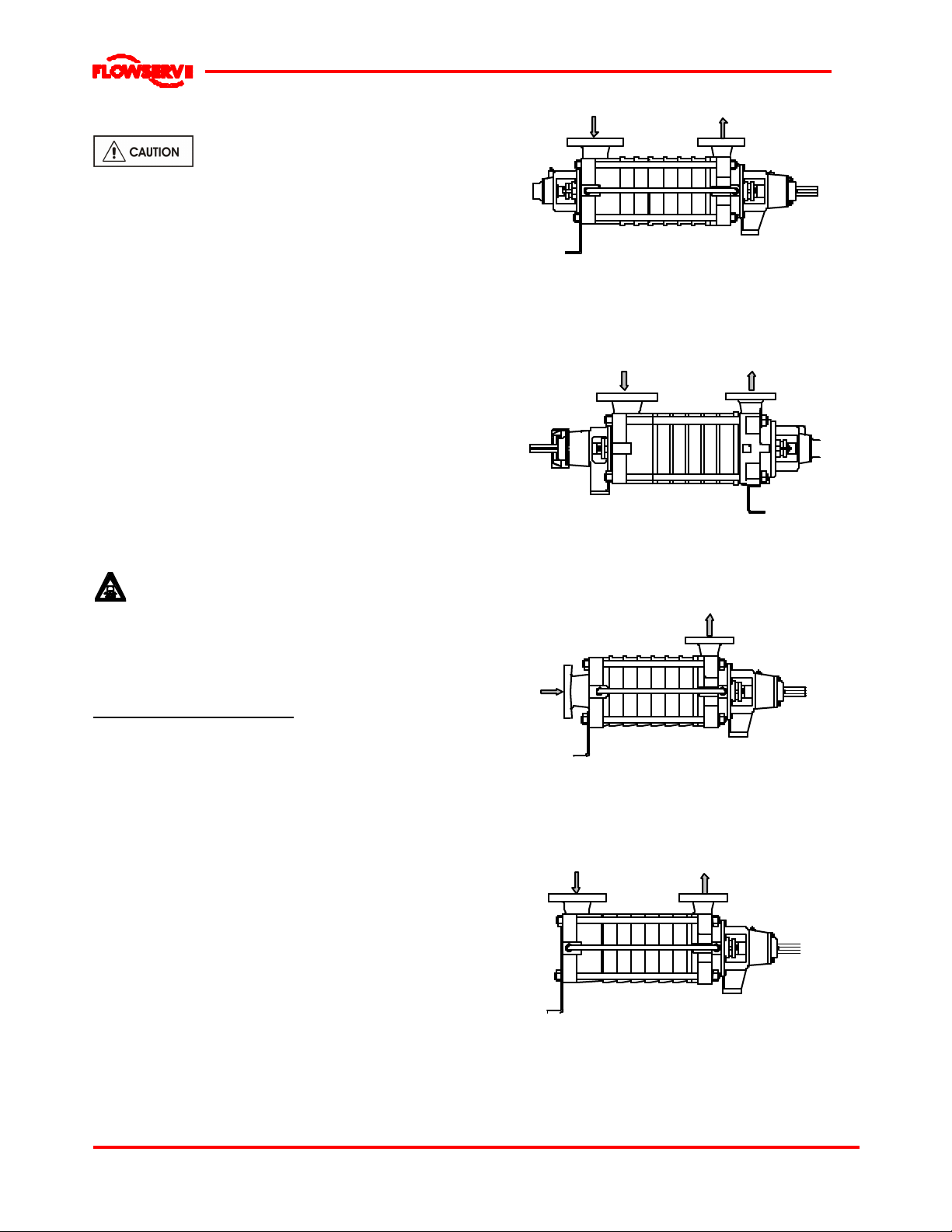
Horizontal
WDXR
Radial suction
Driveend on dischargeside- CW
Thrustbearing ondriveside
Radial bearing onsuction side
2shaftseals
WDXC
Horizontal
Radial suction
Driveend on suction side- CCW
Thrustbearing onsuctionsi de
Radial bearing ondischargeside
2shaftseals
3 PUMP DESCRIPTION
3.1 Configurations
The WDX type pump isa horizontal,multistage,
radial split case, vaned diffuser type centrifugal pump
equipped with a special suctionimpeller for low
NPSH. It can be used with motor, steam turbine and
gasoline ordiesel engine drives.
The WDX pumpsare of modular construction with
identical stages being stacked axially to achieve the
desired pressure output. Four high strength external
tie rods connecting the two end casingshold them
together. A variety of optimal features and materials
allow it to fit a wide range of applications such as
boiler feed or reverse osmosis.
Various orientationsfor the radial suction and
discharge nozzles are allowed every 90°except
towardsthe bottom.
The WDX can have the following configurations:
Horizontal
WDXE
End suction
Driveend on dischargeside- CW
Thrustbearing ondriveside
Sleeve bearing on suctionside
1shaftseal
WDXS
Horizontal
Radial suction
Driveend on dischargeside- CW
Thrustbearing ondriveside
Sleeve bearing on suctionside
1shaftseal
Page 12 of 46
Page 13

WDX USER INSTRUCTIONS ENGLISH 71576322 06-05
®
Year of construction +
Maximumadmi
ssible
Maximum/ minimum
3.2 Nomenclature
Characteristics shown on the nameplate fixed on the pump are as shown below:
Each pump issupplied with the following nameplate:
Speed ofrotation
Pump type
Flowrate
Head
Radial/thrust bearing
Manufacturenumber
Each pump unitis supplied with the following nameplate:
Mass
Pressure at 20°C
temperature
Mass of the set
The pump size will be engraved on the nameplate
typicallyas below:
4 WDX E 6 D
Nominal discharge branch size.
Seriesname
Configuration (see 3.1 above)
Number of stages
Hydraulic type
The typical nomenclatureabove is the general guide
to the WDX configuration description. Identify the
actual pump size and serial numberfrom the pump
nameplate. Checkthat this agrees with the applicable
certification provided.
3.3 Design of major parts
3.3.1 Pump casing
The pump casings(suction, discharge and stage) are
sealed with o’rings and designed to contain the
pressures generated by the pump at the various
possible design pressures and temperatures.
3.3.2 Impeller
Theimpeller is fully shrouded and may be fitted with
optional wear rings.
The suction impelleris specifically designed to have a
low NPSH requirement.
3.3.3 Diffuser
The diffusersare fully machined to optimise
performance.
3.3.4 Shaft
The shaft mounted on bearings with a keyed drive
end.
Page 13 of 46
Page 14
WDX USER INSTRUCTIONS ENGLISH 71576322 06-05
®
3.3.5 Pump bearings andlubrication
WDX pumpsare designed so the antifriction bearings
may be either oil orgrease lubricated.
WDXE and WDXS have product lubricated line
bearingswith sleeve andbushing made of silicon
carbide.
Bearingisolators or stationarylabyrinths maybe fitted
as an optionin the bearing coversto protect the
bearings.
3.3.6 Bearing housing
Grease nipplesenable grease lubricated bearings to
be replenished between major service intervals. For
oil-lubricated bearings, a constant level oilerisfitted.
3.3.7 Stuffing box housing
The stuffing box housing hasa spigot (rabbet) fit
between the pump casing and bearing housing for
optimum concentricity. The design enablesa number
of sealing optionsto be fitted.
3.3.8 Shaft seal
Themechanical seal(s) attached to the pump shaft
sealsthe pumped liquid fromthe environment.
Stuffing boxeshave been designed for component or
cartridge seals. Glandpackingmay be fitted as an
option.
3.3.9 Driver
The driver isnormallyan electricmotor.Differentdrive
configurationsmaybe fitted such asinternal combustion
engines, turbines, hydraulicmotorsetcdriving via
couplings,belts,gearboxes,drive shaftsetc.
3.3.10 Accessories
Accessories may be fitted when specified by the
customer.
3.4 Materials of construction
Material
column
M2 Castiron Cast iron Chrome steel
M3 Carbonsteel Castiron Chrome steel
M4 Carbonsteel
M5 Chrome steel
M6
M7 Stainless steel
Casing Impeller Shaft
Duplex
stainless steel
Stainless
steel
Stainless
steel
Stainless
steel
Stainless
steel
Chrome steel
Chrome steel
stainless steel
stainless steel
Duplex
Duplex
3.5 Performance and operating limits
This product has been selected to meet the
specifications of your purchase order.See the
nameplate and section 1.5.
Themaximumallowable speed forcast iron
impellersis3600RPMand for steel impellersis4000
RPM.
3.5.1Minimal flow
20 % of BEP up to 280° F (140 °C)
25 % of BEP between 280 °F (140 °C) and 410 °F
(210 °C)
3.5.2 Clearance data
Nominal
Interstage
clearance
min/max
mm(inch)
0.170/0.259
(0.0067/0.0102)
0.170/0.259
(0.0067/0.0102)
0.170/0.259
(0.0067/0.0102)
0.170/0.259
(0.0067/0.0102)
0.200/0.303
(0.0079/0.0119)
0.200/0.303
(0.0079/0.0119)
0.200/0.303
(0.0079/0.0119)
0.200/0.303
(0.0079/0.0119)
Size
Mat
M2M30.170/0.259
1.5
M4 toM70.320/0.409
1.5
M2M30.170/0.259
2
M4 toM70.330/0.419
2
M2M30.200/0.303
3
M4 toM70.360/0.463
3
M2M30.200/0.303
4
M4 toM70.410/0.513
4
Nominalwear
ringclearance
min/max
mm(inch)
(0.0067/0.0102)
(0.0126/0.0161)
(0.0067/0.0102)
(0.0130/0.0165)
(0.0079/0.0119)
(0.0142/0.0182)
(0.0079/0.0119)
(0.0161/0.0202)
3.5.3 Sleeve bearing clearance (WDXE/S)
Pump size
1.5 WDX
2WDX
3WDX
4WDX
Diametral clearance
min/max
mm(inch)
0.007 - 0.041
(0.0003- 0.0016)
0.007 - 0.041
(0.0003- 0.0016)
0.007 - 0.041
(0.0003- 0.0016)
0.007 - 0.041
(0.0003- 0.0016)
3.5.4 Bearing bushings
Interstage bearing bushings can bemounted on the
pump. Their numberand location depend on the
material chosen and the number of stagesof the
pump. For furtherinformation, see general
arrangement drawing ofthepump.
Nominal
Balancedrum
clearance
min/max
mm(inch)
0.150/0.226
(0.0059/0.0089)
0.300/0.376
(0.0118/0.0148)
0.170/0.259
(0.0067/0.0102)
0.470/0.559
(0.0185/0.0220)
0.170/0.259
(0.0067/0.0102)
0.480/0.569
(0.0189/0.0224)
0.180/0.269
(0.0071/0.0106)
0.500/0.603
(0.0197/0.0237)
Page 14 of 46
Page 15

3.6 Coverage charts
3.3.1 2970 min-1(50 Hz): coverage charts (Q, H)
3.3.2 3550 min-1(60 Hz): coverage charts (Q, H)
Page 16

WDX USER INSTRUCTIONS ENGLISH 71576322 06-05
®
4 INSTALLATION
Equipment operated in hazardous locations
must comply with the relevant explosion protection
regulations. See section 1.6.4, Products usedin
potentially explosive atmospheres.
All equipment must be grounded.
4.1 Location
The pump should be located to allow room for
access, ventilation, maintenance and inspection with
ample headroom forlifting and should beasclose as
practicable to the supplyof liquid to bepumped.
The pump should be located above the floodlevel.
The pipework should be such that thereis an
adequate NPSH at the pump centreline.The
foundation should provide enough support so that the
pump is not supported by the pipework.
Refer to the general arrangementdrawing for the
pump set.
4.2 Cleaning prior to installation
Remove glue and dirt from suction and discharge
flanges. Check motors to make sure no foreign
objects haveentered through fan and cooling
openings. Remove any compounds on exposed
areasof pump shaft. Cleanpump and motor
nameplate.
A unit mounted on steel workor structural members
should bemounted over oradjacent to girdersor
wallsso that no misalignment will occur from yielding
or sagging of the structure.
Anchor boltsmust be in accordance with the foot bolt
holes. Use anchor bolts of accepted standards and
sufficient to ensure seave fitting in the foundation.
Particularly, thisapplies to individual plateswhere the
anchor boltshave to withstand the driving torque.
Provide sufficient space in the foundation to
accommodate the anchorbolts. Ifnecessary, provide
concrete risers.
4.3.2 Positioning on foundation
Pumpsare generallyshipped mounted, andit is
usuallyunnecessary with unitsof moderate size to
remove the pump or driver from its baseplate when
levelling.
Ensure the following are met:
a) Clean the foundation thoroughly.
b) The baseplate should be mounted onto a firm
foundation, either an appropriate thicknessof
quality concrete or sturdy steel framework
capable of absorbing all normal vibrations. (It
should NOT be distorted or pulled down onto the
surface of the foundation, butshould be
supported to maintain the original alignment).
c) Install the baseplate onto packing pieces evenly
spaced and adjacent to foundation bolts.
4.3 Foundation
Therearemanymethodsof installing
pump units to their foundations. The correct method
dependson the size of the pump unit, itslocation and
noise vibrationlimitations. Non-compliance with the
provision of correct foundation and installationmay
lead to failure of the pump and, assuch, would be
outside the terms of the warranty.
4.3.1 General recommendations
Foundation bolts should belocated or embedded in
the concrete by lay-out ortemplate in relation to the
suction and discharge piping. Foundation bolts of the
specified size maybe enclosed in a pipe sleeve two
or three diameterslarger than the boltsto
compensate forminor variationin alignment.
Standard accessory steel baseplates furnished with
these pumps and motors10 HP (7.5 kW) and under
may be bolted to machine or equipment structures,
either rigidly or,if flexible piping is used, with properly
designed vibration isolators.
d) Level with shims, about 25 mm (1”), between
baseplate and packing pieces.
e) Checkthe horizontal position by meansof a
precision level placed upon an adequate
reference (discharge flange, machined surfaces
of casings etc...).Tolerances within 0.5 mm per
m (0.006in per ft).
f) The pumpanddriver havebeenaligned before
dispatchhowever thealignmentofpump and motor
half couplingmustbe checked. Ifthisisincorrect,it
indicates that the baseplate hasbecome twisted
and should be corrected by re-shimming.
Page 16 of 46
Page 17

WDX USER INSTRUCTIONS ENGLISH 71576322 06-05
®
barriers
g) If anchorboltshave been embeddedin the
foundation, slightly tighten the anchor bolts.
Otherwise let them hang in the foundation holes.
h) If not supplied, guarding shall be fitted as necessary
to meet the requirementsofEN292and EN953 and
orany applicable local safety regulations.
4.4 Grouting
Where applicable, groutin the foundation bolts.
Grouting provides solid contact between the pump
unit and foundation prevents lateral movement of
running equipment and dampens resonant vibrations.
Prepare the site forgrouting.Beforegrouting clean
the foundation surface thoroughly. Provide external
barriers asshown:
4.5.1 Thermal expansion
The pump and motor will normally
have to be aligned at ambient temperatureand
should be corrected to allow for thermal expansion at
operating temperature. In pump installationsinvolving
high liquid temperatures, the unit should be run atthe
actual operating temperature, shut down and the
alignment checked immediately.
4.5.2 Alignment methods
Ensure pump and driver areisolated
electrically and the half couplings are disconnected.
Ensure that the pump pipework, suction and
discharge,is disconnected.
The alignment MUST be checked.
Although the pump will havebeen aligned at the
factoryit is most likely that this alignment will have
been disturbed during transportation or handling. If
necessary, align themotor to the pump, not the pump
to the motor.
Prepare grouting product (concrete, resin) in
accordance withmanufacturers' instructions.
(Use anti-shrink products)
To grout up to the required level. Polish surfaces.
Take necessary precautions to avoid air bubbles.
Lay-down the barrier, break external angles and
polish the different surfaces.
Foundation bolts should only be fully tightened when
the grout hascured.
4.5 Initial alignment
Pump-Driver unit supplied assembled on their
baseplate:
Themachines have originally been aligned in the
work-shop.
Pump and Driver supplied on separate baseplates:
Themachines have originally been mounted on their
respective baseplate in the workshop. The pumpis to
be installed first and should be considered as the
fixedpoint.The alignment is then performedon the
driveralone.
Before aligning verify that the pump is horizontal by
using a flange surface or otherhorizontal surface.
Adjust if necessary by adjusting the height of the
wobble foot. Tighten any nuts that have been
loosened.
Alignmentisachieved by adding or removing shims
under themotor feet and also moving the motor
horizontally as required. In some cases where the
alignment cannot be achieved it will be necessary to
move the pump before recommencing the above
procedure.
Before connecting the couplings verify
the motor rotation direction.
For couplings with narrow flangesuse a dial indicator
as shown below to check both parallel and angular
alignment.
Page 17 of 46
Page 18

WDX USER INSTRUCTIONS ENGLISH 71576322 06-05
®
Parallel
Angular
Maximum permissible misalignment at working
temperature:
Parallel 0.2 mm (0.008 in.)TIR
Angular 0.1 mm (0.004 in.) TIR
When checking parallel alignment, the total indicator
read-out (TIR) shown is twice the value of the actual
shaft displacement.
Alignin thevertical plane first, then horizontally by
movingmotor.When performing final alignment,check
for soft-foot under the driver. A TIR indicatorplacedon
the coupling, readingin the vertical direction, should not
indicate more than 0.05mm (0.002 in.)movement when
anydriverfoot fastenerisloosened.
Whilethe pumpiscapable of operating with the
maximum misalignment shownabove, maximum pump
reliabilityis obtained by nearperfect alignment of 0.05
to 0.10 mm (0.002 to0.004in.)TIRparallel and
0.05mm (0.002in.)per100mm (4in.) of coupling
flange diameter asTIR angular misalignment.This
coversthefull series of couplings available.
Pumpswith thick flanged non-spacer couplings can
be alignedby using a straight-edge across the
outsidediametersof the coupling hubsand
measuring the gap between the machined faces
using feeler gauges, measuring wedge or calipers.
When the electric motor has sleeve bearings it is
necessary to ensure that themotor isaligned to run
on its magnetic centreline.
Refer to themotor manual for details.
A button (screwed into one of the shaft ends)is
normally fitted between the motorand pump shaft
ends to fix the axial position.
If the motor does not run in its
magneticcentre the resultantadditional axial force
may overload the pump thrust bearing.
Complete piping asbelow and see sections4.7,
Final shaft alignment check up to and including
section 5, Commissioning, startup, operation and
shutdown before connecting driver and checking
actual rotation.
4.6 Piping
The user must verify that the equipment is
isolated from any external sources of vibration.
Protective coversare fitted to the pipe
connectionsto prevent foreign bodies entering during
transportation andinstallation. Ensure that these
coversare removed from the pump before connecting
anypipes.
4.6.1 Suction and discharge pipework
In order to minimize friction losses and hydraulic
noise in the pipeworkit is good practice to choose
pipeworkthatisone or two sizes larger than the
pump suction and discharge.Typicallymain pipework
velocitiesshould not exceed 2 m/s (6 ft/sec) suction
and 3 m/s (9 ft/sec) on the discharge.
Takeinto account the available NPSH must be higher
than the required NPSH of the pump. When
determining the NPSH available the vapour pressure
at the operating temperature must be taken into
account.
Never use the pump as a support for
piping.
Maximum forces and moments allowed on the pump
flangesvary with the pump size and type.To
minimize these forcesandmoments thatmay,if
excessive, cause misalignment, hot bearings, worn
couplings, vibration and the possible failure of the
pump casing, the following points should be strictly
followed:
Prevent excessive external pipe load
Never drawpiping into place by applying forceto
pump flange connections.
Do not mount expansionjoints so that their force,
due to internal pressure, acts on the pump flange.
It isrecommended that expansion jointsuse
threaded rod to limit any forcesof thistype.
Thermal expansions must be compensatedin
such a way that no additional forces act on the
pump flanges.
Make sure that piping flanges are square and
concentric to the pump flanges.
Page 18 of 46
Page 19

WDX USER INSTRUCTIONS ENGLISH 71576322 06-05
®
The table in 4.6.3 summarizes the maximum forces
and moments allowed on WDX pump casings. Refer
to Flowserve forother configurations.
Ensure piping and fittings are flushed
before use.
Ensure piping for hazardous liquids is arranged
to allow pump flushing before removal ofthe pump.
Excessive external strains(forces, moments)
may causemisalignment, general vibrations, hot
bearingsor excessive wear on couplingsand seals.
In extreme cases, leakage may result with potential
lossof life with hot or corrosive liquids.
4.6.2 Suction piping
Refer to the diagrams below for typical designs of
suction piping for both flooded suction and suction lift.
a) Theinlet pipe should be one or two sizes larger
than the pump inlet boreand pipe bends should
be as large a radius aspossible.
b) Pipeworkreducers should be conical and have a
maximum total angle of divergenceof 15 degrees.
c) Pipeworkshould be arranged to avoidair pockets.
d) If high pointscannot beavoided on the suctionline
equip them with air relief cocks.
e) On suction lift the piping should be inclined up
towardsthe pumpinlet with eccentric reducers
incorporated to prevent air locks.
f) On positive suction, the inlet piping must have a
constant fall towards the pump.
g) Flow should enterthe pump suction with uniform
flow, to minimize noise and wear. Thisis
particularly important on large or high-speed
pumpswhich should have a minimum of five
diameters of straight pipe on the pump suction
between the elbow and inlet flange. See section
10.3, Reference 1, for more detail.
h) Inlet strainers, when used, should have a net `free
area' of at least three times the inlet pipe area.
i) Do notinstall elbowsat an angle other than
perpendicular to the shaft axis. Elbowsparallel to
the shaft axis will cause uneven flow.
j) Except in unusual circumstancesstrainersare
not recommended in inlet piping. If considerable
foreign matter is expected a screen installed at
the entrance to the wet well is preferable.
k) Fitting anisolation valve will allow easier
maintenance.
l) If an inlet valve is necessary, choose a model
with full bore so as to limitlosses. Valve stem
should bein a vertical position. There should be
a minimum of five pipe diametersbetween the
pump and the valve.
m) Never throttle pump on suction side and never
place a valve directly on the pump inlet nozzle.
n) Do not tighten flanges before the final check.
Typical design –flooded suction
Note:
Ideallyreducers should be limited toone pipediameter change,
ie 150 mm (6 in.) to 200 mm (8 in.). Must have a maximumtotal
angleof divergence of15 degrees.
Typical design –suction lift
Notes:
1. S = Minimum submergence >3E.
2. Ideallyreducers to be limitedto one pipediameter change,
ie 150 mm (6 in.) to 200 mm (8 in.). Must have a maximumtotal
angleof divergence of 15 degrees.
Page 19 of 46
Page 20

WDX USER INSTRUCTIONS ENGLISH 71576322 06-05
®
4.6.3Maximum forces and momentsallowed on WDX pump flanges
Direction of forces
Fx = horizontal parallel to pump axis
Fy = horizontal perpendicular to pump axis
Fz = vertical perpendicular to pump axis
Direction of moments
Mx = around a horizontal axis parallel to pump axis
My = around a horizontal axis nozzle axis
Mz = around a horizontal axis perpendicular to pump axis
PIPE
CONFIGURATION
Vertical pipework 50 mm
perpendicular 3in
totheshaft 80 mm
Horizontal pipework 3 in
perpendicular 80 mm
totheshaft 4 in
Horizontal 4in
within the pump axis 100 mm
FLANGE FORCES MOMENTS
Diameter Fy Fz Fx F My Mz Mx M
1.5 in
40 mm
2in
4in
100 mm
6in
150 mm
1.5 in
40 mm
2in
50 mm
100 mm
6in
150 mm
3in
80 mm
6in
150 mm
130 lbf 200 lbf 160 lbf 290 lbf 170 ft-lbf 260 ft-lbf 340 ft-lbf 460 ft-lbf
58 daN 89 daN 71 daN 128 daN 23 daN.m 35 daN.m 46 daN.m 62 daN.m
130 lbf 200 lbf 160 lbf 290 lbf 170 ft-lbf 260 ft-lbf 340 ft-lbf 460 ft-lbf
58 daN 89 daN 71 daN 128 daN 23 daN.m 35 daN.m 46 daN.m 62 daN.m
200 lbf 300 lbf 240 lbf 430 lbf 350 ft-lbf 530 ft-lbf 700 ft-lbf 950 ft-lbf
89 daN 133 daN 107 daN 193 daN 47 daN.m 72 daN.m 95 daN.m 128 daN.m
260 lbf 400 lbf 320 lbf 570 lbf 500 ft-lbf 740 ft-lbf 980 ft-lbf 1330ft-lbf
116 daN 178 daN 142 daN 256 daN 68 daN.m 100 daN.m 133 daN.m 180 daN.m
460 lbf 700 lbf 560 lbf 1010 lbf 870 ft-lbf 1300 ft-lbf 1700ft-lbf 2310ft-lbf
205 daN 311 daN 249 daN 448 daN 118 daN.m 176 daN 230 daN.m 313 daN.m
130 lbf 200 lbf 160 lbf 290 lbf 170 ft-lbf 260 ft-lbf 340 ft-lbf 460 ft-lbf
58 daN 89 daN 71 daN 128 daN 23 daN.m 35 daN.m 46 daN.m 62 daN.m
130 lbf 200 lbf 160 lbf 290 lbf 170 ft-lbf 260 ft-lbf 340 ft-lbf 460 ft-lbf
58 daN 89 daN 71 daN 128 daN 23 daN.m 35 daN.m 46 daN.m 62 daN.m
200 lbf 300 lbf 240 lbf 430 lbf 350 ft-lbf 530 ft-lbf 700 ft-lbf 950 ft-lbf
89 daN 133 daN 107 daN 193 daN 47 daN.m 72 daN.m 95 daN.m 128 daN.m
260 lbf 400 lbf 320 lbf 570 lbf 500 ft-lbf 740 ft-lbf 980 ft-lbf 1330ft-lbf
116 daN 178 daN 142 daN 256 daN 68 daN.m 100 daN.m 133 daN.m 180 daN.m
460 lbf 700 lbf 560 lbf 1010lbf 870 ft-lbf 1300 ft-lbf 1700 ft-lbf 2310 ft-lbf
205 daN 311 daN 249 daN 448 daN 118 daN.m 176 daN 230 daN.m 313 daN.m
240 lbf 200 lbf 300 lbf 430 lbf 350 ft-lbf 530 ft-lbf 700 ft-lbf 950 ft-lbf
107 daN 89 daN 133 daN 193 daN 47 daN.m 72 daN.m 95 daN.m 128 daN.m
320 lbf 260 lbf 400 lbf 570 lbf 500 ft-lbf 740 ft-lbf 980 ft-lbf 1330ft-lbf
142 daN 116 daN 178 daN 256 daN 68 daN.m 100 daN.m 133 daN.m 180 daN.m
560 lbf 460 lbf 700 lbf 1010lbf 870 ft-lbf 1300 ft-lbf 1700 ft-lbf 2310 ft-lbf
249 daN 205 daN 311 daN 448 daN 118 daN.m 176 daN.m 230 daN.m 313 daN.m
Notes:
1) F = External force (tension or compression).
M = External moment, clockwise or counter-clockwise.
2) Forces and moments may be appliedsimultaneously inany
direction.
3) Values apply to all materials.
4) Higher loads maybe applicable, if direction and magnitude of
individual loads are known, but these need written approval
fromFlowserve PumpDivision.
5) Pumps must be onrigidfoundations andbaseplates must be
fullygrouted.
6) Pump/baseplate should not be used as pipe anchor. Suction
and dischargepiping should beanchored asclose as possible
tothe pump flanges toreduce vibration and prevent strainon
the pump casing. Expansion joints are recommended. They
must be properlytied andlocated on thesideof the pipe anchor
awayfromthe pump
7) The pump mounting bolt torquesspecifiedmust be usedto
prevent relative movement betweenthe pump casing and
baseplate.(Seesection 6.6, Fastener torques.). The bolt
materialmust havea minimum yieldstrength of 600N/mm
(87000lb/in.2).
2
Page 20 of 46
Page 21

WDX USER INSTRUCTIONS ENGLISH 71576322 06-05
®
4.6.4 Discharge piping
See section 4.6.2 for typical pipeworkdesign.
A non-return valve should belocated in the discharge
pipeworkto protect the pump from excessive back
pressure and hence reverse rotation when the unit is
stopped.
Pipeworkreducers should have a maximum total
angle of divergence of 9 degrees.
Fitting anisolation valve will alloweasiermaintenance.
It should be installed downstream of thenon-return
valve.
If needed a control pressure gaugemay be installed
on the pipework.
Do not tighten the pipe flanges before the final check.
4.6.5 Auxiliary piping
4.6.5.1 Drains
Pipe pump casing drains and glandleakage to a
convenient disposal point.
4.6.5.2 Pumps fitted with mechanical seals
Single seals requiring re-circulation will normally be
provided with the auxiliarypiping from pump casing
already fitted.
If the seal requires an auxiliary quench then a
connectionmust be made to a suitable source of
liquid flow,lowpressure steam or static pressure from
a header tank. Recommended pressure is0.35 bar (5
psi) or less. Check General arrangement drawing.
Special seals may requiredifferent auxiliary piping to
that described above. Consult separate User
Instructionsand or Flowserve if unsure of correct
method orarrangement.
For pumping hot liquids, to avoid seal damage,it is
recommended that any external flush/cooling supply
be continued after stopping the pump.
4.6.6 Final checks
Check the tightnessof all bolts in the suction and
discharge pipework. Tightenif necessary. Check also
the tightnessof all foundation bolts. Tighten if
necessary. Checkthe tightness of all auxiliary piping.
Tightenif necessary.
4.7 Final shaft alignment check
After connecting piping to the pump, rotate the shaft
several times by hand to ensure there is no binding
and all partsare free.
Recheck the coupling alignment, aspreviously
described, to ensure no pipe strain. If pipe strain
exists, correct piping.
Alignment can only be considered definitive after
pipeworkhas been connected.
4.8 Electrical connections
4.8.1 Safety conditions about electrical
connections
Electrical connectionsmust be made
by a qualified Electrician in accordance with relevant
local national and international regulations.This
includes any grounding.
It is important to be aware of the EUROPEAN
DIRECTIVE on potentially explosive areaswhere
compliance with IEC60079-14 is an additional
requirement for making electrical connections.
Avoid mechanical, hydraulic or electrical
overload byusing motor overload tripsor a power
monitor and make routine vibration monitoring.
Itis important tobe aware of the EUROPEAN
DIRECTIVEon electromagneticcompatibility when
wiringup andinstalling equipment on site.Attention
must be paid toensure that the techniquesused during
wiring/installationdonotincrease electromagnetic
emissionsor decrease the electromagneticimmunityof
theequipment, wiring oranyconnected devices. Ifin
anydoubt, contact Flowserve foradvice.
The motormust be wired upin
accordance with the motor manufacturer's
instructions(normally supplied within the terminal
box)including anytemperature, earth leakage,
current and otherprotective devices asappropriate.
Theidentification nameplate should be checked to
ensure the power supply is appropriate.
A device toprovide emergency stopping must
be fitted.
If not supplied pre-wired to the pump unit, the
controller/starterelectrical detailswill also be supplied
within the controller/starter.
For electrical detailson pump sets with controllers
see the separate wiring diagram.
See section 5.3, Direction of rotation
before connecting the motor to the electrical supply.
Page 21 of 46
Page 22

WDX USER INSTRUCTIONS ENGLISH 71576322 06-05
®
4.9 Protectionsystems
The following protection systemsare
recommended particularly if the pump is installed in a
potentially explosive area or is handling a hazardous
liquid. Ifin doubt consult Flowserve.
If there is any possibilityof the system allowing the
pump to run against a closed valve or below
minimum continuoussafe flowa protection device
should beinstalled to ensure the temperatureof the
liquid does not rise to an unsafe level.
If there are any circumstancesin which the system
can allow the pump to run dry, or start up empty, a
powermonitor should be fitted to stop the pump or
preventit from being started.This is particularly
relevant if the pump ishandling a flammable liquid.
If leakage of product from the pump or its associated
sealing system can cause a hazard it is
recommended that an appropriate leakage detection
system isinstalled.
To prevent excessive surface temperatures at
bearingsit is recommended that temperature or
vibration monitoring are carried out. See sections
5.7.4 and 5.7.5.
If a defect of cooling can lead to temperature higher
than those acceptable a system of cooling
surveillance must be installed.
In the case of product lubricated
bearingsthe sourceof product supply should be
checked against the order.There maybe
requirementsfor an external clean supply, particular
supply pressure or the commencement of lubrication
supply before pump start-up.
5.1.2 Oil Lubrication
The bearingsare lubricated by pins. A constant level
oiler automatically maintainsthe correct oil level.
The oiler suppliesthe necessary quantity of oil. It
operates on theliquid seal principal and feedswith oil
only when the quantity of oil becomes toolow in the
bearing. It will stop to feed once a sufficient quantity
of oil is in the bearing.
The reserve contained in the reservoir refills
automatically the natural losses of the bearing. As
soon as the oil level approaches the minimum level of
the reservoir, refill the reservoir.
Regarding the qualityand the quantity of the oil to be
used, refer to the lubrication table and information
below.
Foroil lubricated pumps,fill the bearing
housing with correctgrade of oil to thecorrectlevel,ie
sightglassor constant level oilerbottle.
Except when explicitly required bythe customerin
the specifications, when a possibility of reverse
rotation existsthe customermust install a reverse
rotation protection device.
The customer must install all equipment required to
avoid water hammer.
5 COMMISSIONING, START-UP,
OPERATION AND SHUTDOWN
These operations must be carried out by
fully qualified personnel.
5.1 Pre-commissioning procedure
5.1.1 Lubrication
Determine the mode of lubrication of the pump set,
eg grease, oil, product lubrication etc.
Grease lubricated pumpsand electric motors are
supplied pre-greased.
Otherdriversand gearboxes, if appropriate, should
be lubricatedin accordance with their manuals.
See below for the correct side on which constant
level oilersshould be installed.
Oiler
Direction of rotation of
thepump
Driveendside
Oiler
When fitted with a constant level oiler, the bearing
housing should be filled onlybyunscrewing or
hinging backthe transparent bottle and filling the
bottle with oil.Do notfill the bearing housing through
the breather hole.
Page 22 of 46
Page 23

WDX USER INSTRUCTIONS ENGLISH 71576322 06-05
®
Oil levels are as indicated below. The distance
indicated is distance below the shaft centreline.
The oil filled bottle should then be refitted so as to
returnit to the upright position. Filling should be
repeated until oil remainsvisible within the bottle.
Pump size
Oil Level mm (inch)
Drive end Non Drive end
1.5 WDX 41 (1.61) 41 (1.61)
2 WDX 46 (1.81) 46 (1.81)
3 WDX 56 (2.20) 46 (1.81)
4 WDX 66 (2.60) 46 (1.81)
5.2 Pump lubricants
5.2.1 Recommended oil lubricants
Viscosity grade ISO 46
Ambient temperature
Bearings temperature 80 °C maximum
MANUFACTURER TYPE
CHARACTERISTICS
BP
ENERGOL
HLP 46
ELF
TURBELF
SA 46
Density at 15 C 0.885 0.881 0.868 0.878 0.87 0.872 0.877
Viscosity at 40 °C.cst 45 48.6 43 43 46 46 46
Viscosity at 50 °C.cst 30 31.5 29.4 28 30 29.5 30
Viscosity at 100 °C.cst 6.9 7.1 6.7 7 6.9 6.9 6.8
Pour-point °C - 30 - 27 - 12 - 15 - 30 - 12 - 21
Flash-point °C 210 220 220 220 214 230 230
Fire-point °C 240 252 280 240 245
Aniline point °C 99 102 110 102 109 101 101
Viscosityindex 105 106 109 105 113 100 100
Acid value 0.2 0.6 0.2 0.13 0.7 0.1 0.7 to 1.2
Colour 1 ½ 2 1 2 2 1 ½ 1
TABLE OF EQUIVALENCEAND CHARACTERISTICS
OF RECOMMENDED OILS
ESSO
TERESSO
46
MOBIL
DTE
Medium
SHELL
TELLUS
T 37
TOTAL
PRESLIA
46
TOTAL
AZOLLA
ZS 46
Anti erosion additives yes yes yes yes yes
Foaminhibitors yes yes yes yes yes yes yes
Anticorrosion additives yes yes yes yes yes yes yes
Antioxidant yes yes yes yes yes yes yes
Conradson carbon residue 0.01 0.2
Limits on temperature °C - 12
to
120 °C
110 °C
Saponification < 0.5 1.2
5.2.2 Recommended grease lubricants
Factory greasing : SHELL ALVANIAR2 or equivalent
Equivalent greases : MOBIL, Mobilux EP2
TOTAL, Multis 2
ELF, Elf Multi
Grease Quantity : 10 to 30 Grams
5.2.3 Recommended fill quantities
Oil Quantity
ISOVG 46Pump size
Driveend NonDrive end
1.5 WDX 0.26qt (0.250 Ltr)
2WDX 0.37qt (0.350 Ltr)
3WDX
4WDX
0.42qt (0.400 Ltr) 0.25qt (0.240 Ltr)
0.63qt (0.600 Ltr) 0.32qt (0.300 Ltr)
0.21qt (0.200 Ltr)
0.25qt (0.240 Ltr)
Page 23 of 46
- 21
to
Page 24

WDX USER INSTRUCTIONS ENGLISH 71576322 06-05
®
5.2.4 Lubrication schedule
5.2.4.1 Oil lubricated bearings
Operating conditions and severity ofservice will
determine the intervals between oil changes. In
general higheroil temperatures will require more
frequent oil changes.
For pumps on hotservice orin severely damp or
corrosive atmosphere, theoil will requirechanging
more frequently. If the bearings maintain a stable
temperature andif there has been no contamination
of the oil,the interval between changes maybe
longer.
Lubricantand bearing temperature analysis can be
useful in optimising lubricant changeintervals.
Generally, the oil should be changed every 6 months.
If the bearing temperature increases, check
immediately for improperlubrication or a faulty
bearing.
The lubricatingoil shouldbe a high qualitymineral oil
having foam inhibitors. Syntheticoils mayalso be used
if checks show that the rubberoil seals will notbe
adversely affected.
The bearing temperature may be allowed to rise to 50
ºC (122 ºF).above ambient, but should not exceed 82
ºC (180 ºF).A continuously rising temperature or an
abrupt rise, indicate a fault.
5.2.4.2 Grease lubricated bearings
The bearingsare prelubricated when supplied.
Lubrication frequencyis asindicated in the table
below. After a 2 yearsperiod the bearing should be
completely cleaned, checked and repacked with new
grease.
The free bearing space shouldnot be filled up more
that 50 % to 60 % of its content see 5.2.3. Care must
be taken to avoid both under and over-lubrication.
Over lubrication will cause the bearings to run hotter
than normal, while under-lubricated bearingscould
wear prematurely.
The characteristics of theinstallation and severityof
service will determine the frequencyof lubrication.
Lubricantand bearing temperature analysis can be
useful in optimising lubricant changeintervals.
Pump size
1,5 WDX 3000 2200 1500 1200
2WDX 3000 2200 1500 1200
3WDX 2700 2000 1400 1100
4WDX 2500 1700 1300 1000
Lubrication frequencies in hours of operation
1450 RPM 1750 RPM 2950 RPM 3550RPM
Never mix greasescontaining different
bases, thickenersor additives.
5.3 Direction of rotation
Starting or operating pumps with the
wrong direction of rotation can be harmful to the
pumps.
Ensure that the pump rotation is the same as the
arrow on the pump casing.
It ispreferable to check the direction of rotation
before installing the coupling. If not, the pump must
be filledin with theliquid beforestart-up.
If maintenance work has been carried
out to the site's electricity supply, the direction of
rotation should be re-checked asabove in case the
supply phasing has been altered.
5.4 Guarding
Guarding is supplied fitted to the pump set.
If this has been removed or disturbedensure that all
the protective guardsaround the pump coupling and
exposed parts of the shaft are securely fixed.
5.5 Primingand auxiliary supplies
Where there is any riskof the pump being run
against a closed valve generating highliquid and
casing external surface temperatures it is
recommended that usersfit anexternal surface
temperature protection device.
Ensure all electrical, hydraulic,
pneumatic, sealant andlubrication systems(as
applicable) areconnected and operational.
Ensure theinlet pipe and pump casing
are completely full of liquid before starting continuous
duty operation.
These operationsmust be carried out by personnel
with approved qualifications.
Page 24 of 46
Page 25

WDX USER INSTRUCTIONS ENGLISH 71576322 06-05
®
5.5.1 Suction pressure above atmospheric
pressure
Open the air vent connection to allow the trapped air
to escape. Let liquid run out until free from air
bubbles.
5.5.2 Suction liftwith footvalve fitted
Fill suction pipe and casing with liquid at a pressure
of 1 to 2 bar from an external source. Vent as
describedin section 5.5.1.
h) Ensure all vent connectionsare closed
before starting.
i) Start motorand check outlet pressure.
j) If the pressure is satisfactory, slowly OPEN outlet
control valve.
k) Do not run the pump with the
outlet valve closed for a period longer than 20
seconds.
l) If NO pressure, or LOWpressure, STOP the
pump. Refer to section 7, Faults; causesand
remedies, for fault diagnosis.
5.7 Running the pump
5.7.1 Venting the pump
Vent the pump to enable all trapped air to
escape taking due care with hot or hazardous liquids.
Under normal operating conditions, after the pump
hasbeen fullyprimed and vented, it should be
unnecessary to re-ventthe pump.
5.7.2 Pumps fittedwith packed gland
Foot valves are not recommended when
the pumped liquid has suspended solid particles.
Theymay lodge between foot valve seat and shutter.
5.5.3 Suction liftwithout foot valve
Pump casing vents on the suction volute must be
connected to an external vacuum pump priming
system. If in doubt, please consult Flowserve.
5.6 Startingthe pump
a) Ensure flushing and/or cooling/
heating liquid supplies are turned ON before
starting the pump.
b) CLOSE the outlet valve. If the pump isequipped
with a non-return flow valve andis to be started
with an opened discharge valve, verify that it is
closed by an adequate back pressure.
c) OPEN all inlet valves.
d) Open all valves of theminimal flowline to ensure
a minimal flow for the period the pump isrunning
against the closed discharge valve.
e) Prime the pump.
f) Check that all plugs are tight.
g) Checkthat the gland lightly tightens the packing.
If the pump has a packed gland theremust be some
leakage from the gland. Gland nutsshould initially be
finger-tight only. Leakage should take place soon
afterthe stuffing boxis pressurized.
Page 25 of 46
Page 26

WDX USER INSTRUCTIONS ENGLISH 71576322 06-05
®
The gland must be adjusted evenly to give
visible leakage and concentric alignment of the gland
ring [4120] to avoid excesstemperature. If no
leakage takes place the packing will begin to
overheat. If overheating takesplace the pump should
be stopped and allowed to cool beforebeing restarted. When the pump isre-started, check to
ensure leakage is taking place at thepacked gland.
If hotliquids are being pumped it may be necessary
to slacken the gland nuts to achieve leakage.
The pump should be run forten minuteswith steady
leakage and the gland nuts tightened by 10 degrees
at a time until leakage isreduced to an acceptable
level.The temperature of the gland should be
checked aftereach round of tightening.If the
temperature startsto climb rapidly then back off the
gland nuts until the temperature drops down. Wait for
the temperature to stabilize beforetightening again.
Theleakage must not be reduced belowa rate of 20
dropsperminute. Bedding in ofthe packing may take
several hours.
Care must be taken when adjusting the gland
on an operating pump. Safety gloves are essential.
Loose clothing must not be worn to avoid being
caughtup by the pump shaft.Shaft guards must be
replaced after the gland adjustmentis complete.
If bearing temperaturesare to be monitored it is
essential that a benchmarktemperature isrecorded
at the commissioning stage and after thebearing
temperature has stabilized.
Record the bearing temperature (t)and the
ambient temperature (ta)
Estimate the likely maximum ambient
temperature (tb)
Set the alarm at (t+tb-ta+5) C [(t+tb-ta+10) F]
and the trip at 100 C (212 F) foroil lubrication
and 105 C (220 F) for grease lubrication
It isimportant, particularly with grease lubrication, to
keep a checkon bearing temperatures. After start up
the temperature rise should be gradual, reaching a
maximum afterapproximately1.5 to 2 hours. This
temperature rise should then remain constant or
marginallyreduce with time. (Refer to section 6.2.3.1
for furtherinformation.)
5.7.5 Normalvibration levels, alarm and trip
For guidance, pumps generally fall under a
classification for rigid support machines within the
International rotating machinery standards and the
recommended maximum levels below are based on
those standards.
Alarm and trip values for installed
pumpsshould be based on the actual measurements
(N) taken on site on the bearing housingsof the
pump in the fully commissioned as new condition.
Never run gland packing dry,even for
a short time.
5.7.3 Pumps fittedwith mechanical seal
Mechanical sealsrequire no adjustment. Any slight
initial leakage will stop when the seal isrun in.
Before pumping dirty liquids it isadvisable, if
possible, to run in the pump mechanical seal using
clean liquid to safeguard the seal face.
External flush orquench should be
started before the pump is run and allowed to flow for
a period after the pump has stopped.
Never run a mechanical seal dry,even
for a short time.
5.7.4 Bearings
If the pumps are working in a potentially
explosive atmosphere, temperature or vibration
monitoring at the bearingsis recommended.
The example (N) valueisgiven for the preferred
operating flow region (typically this mayextend to 70
to 120 % of the pump best efficiency point); outside
the preferred flow region theactual vibration
experienced may be multipliedby up to 2.
These standard valuescan vary with the rotational
speed and the power absorbed by the pump. For any
special case, do not hesitate to consult us.
Measuring vibration at regular intervalswill then show
anydeteriorationin pump or system operating
conditions.
Vibration Velocity - unfiltered
Normal N 5.6 (0.22)
Alarm N x 1.25 7.1(0.28)
ShutdownTrip N x 2.0 11.2( 0.44)
Horizontal Configuration
mm/s(in./s) r.m.s.
5.7.6 Stop/start frequency
Pump setsare normally suitable for the numberof
equally spaced stop/startsper hour shown in the
table below. Checkactual capability of the driverand
control/starting system before commissioning.
Page 26 of 46
Page 27

WDX USER INSTRUCTIONS ENGLISH 71576322 06-05
®
Motor rating kW (hp)
Up to 15 (20) 15
Between 15( 20) and 90 (120) 10
90(120)to150( 200) 6
Above150( 200) Refer
Maximum stop/starts
perhour
Where dutyand standbypumps are installeditis
recommended thattheyare run alternately every week.
5.8 Stopping and shutdown
a) Close the outlet valve, but ensure
that the pump runsin this condition for no more
than a few seconds.
b) Stop the pump.
c) Avoid having the unit turn in the opposite
direction of the normal running conditions
d) Protect the pump against water hammer.
e) Make sure that the discharge line pressure does
not reach the foot valve.
f) Switch off flushing and/or cooling/heating liquid
supplies at a time appropriate to the process.
g) For prolonged shut-downs and
especially when ambient temperatures are likely
to drop below freezing point, the pump and any
cooling and flushing arrangements must be
drained orotherwise protected. When draining
the pump, first verify that theliquid temperature
hascooled sufficientlyto allow safe maintenance.
5.9 Hydraulic, mechanical and electrical
duty
This product has been supplied to meet the
performance specifications of your purchase order,
however it isunderstood thatduring the life of the
product these may change.The followingnotesmay
help the user decide how to evaluate the implications
of any change. If in doubt contact your nearest
Flowserve office.
5.9.1 Specific gravity (SG)
Pump capacity and total headin meters(feet) do not
change with SG, howeverpressure displayed on a
pressure gaugeis directly proportional to SG.Power
absorbed is also directly proportional to SG. It is
thereforeimportant to checkthat any change in SG
will not overload the pump driveror over-pressurize
the pump.
5.9.2 Viscosity
For a given flow rate the total head reduceswith
increased viscosity and increaseswith reduced
viscosity.Also fora given flow rate the power
absorbed increaseswith increased viscosity, and
reduces with reduced viscosity.
It isimportant that checks are made with yournearest
Flowserve office if changesin viscosity are planned.
5.9.3 Pump speed
Changing pump speed effectsflow, total head, power
absorbed, NPSHR, noise and vibration. Flow variesin
direct proportion to pump speed, head varies as
speed ratio squared and power variesas speed ratio
cubed.The new duty, however, will also be
dependent on the system curve. If increasing the
speed, it isimportant thereforeto ensure the
maximum pump working pressure is not exceeded,
the driver is not overloaded, NPSHA> NPSHR, and
that noise and vibration arewithin local requirements
and regulations.
5.9.4 Net positiv e suction head (NPSHA)
NPSH available (NPSHA)isthe head available at the
impeller inlet, above the vapourpressure of the
pumpedliquid.
NPSH required (NPSHR)isthe minimum head required
at theimpellerinlet,above thevapourpressure of the
pumpedliquid,to avoid excessive cavitation and
extreme performance degradation.
It isimportantthat NPSHA> NPSHR. The margin
between NPSHA> NPSHRshould beas large as
possible.
If any change in NPSHAisproposed,ensure these
margins are not significantly eroded. Referto the
pump performance curve to determine exact
requirementsparticularlyif flow has changed. If in
doubtplease consult yournearest Flowserve office
for advice and detailsof the minimum allowable
margin for your application.
5.9.5 Pumped flow
Flowmust not fall outside the minimum and
maximum continuoussafe flow shown on the pump
performance curve and or data sheet.
5.10 Pumps for Food Use or Potable
Water
If the pump has notbeen specifically ordered for a
food or drinking water application it must not be used
for these typesof applications. If it hasbeen ordered
for this type of application the following
recommendationsare to be followed.
5.10.1 Cleaning prior to operation
Pumpsthat are to be used for a food or drinking
water application should be cleaned before being put
intoinitial operation and after the installationof spare
partsthat are in contact with the liquid.
Page 27 of 46
Page 28

WDX USER INSTRUCTIONS ENGLISH 71576322 06-05
®
Cleaning once the pump has been commissioned will
depend on the application and operating conditions.
The user must ensure that the cleaning procedures
are suitable for the application and operating
conditions, and local regulations.
6 MAINTENANCE
6.1 General
If a belt drive is used, the assembly and tension
of the belts must be verified during regular
maintenance procedure.
In dirty or dusty environments, regular checks
must be made and dirt removed fromareas around
close clearances, bearing housingsand motors.
It is the plant operator'sresponsibility to ensure
that all maintenance, inspectionand assembly work
iscarried out byauthorized and qualified personnel
who have adequatelyfamiliarized themselveswith
the subjectmatter by studying this manual in detail.
(See also section 1.6.2.)
Any workon the machine must be performed when it
isat a standstill. Itisimperative that the procedure for
shutting down themachine isfollowed, asdescribed
in section 5.8.
On completion ofwork all guards and safetydevices
must be re-installed and made operative again.
Before restarting the machine, the relevant
instructionslisted in section 5, Commissioning, start
up, operation and shut down must be observed.
Oil and grease leaks may make the ground
slippery. Machine maintenance must always
begin and finish by cleaning the ground and the
exterior of the machine.
If platforms, stairsand guard railsare required for
maintenance, they must be placed for easy accessto
areaswhere maintenance and inspection are to be
carried out. The positioning ofthese accessories
must notlimit accessor hinder the lifting of the part to
be serviced.
When air or compressed inert gasis used in the
maintenance process, the operator and anyone in the
vicinity must be careful and have the appropriate
protection.
Do not spray air or compressed inertgason skin.
Do not direct an air or gas jet towards other people.
Never use air or compressed inertgasto clean
clothes.
Before working on the pump, take measures to
prevent an uncontrolled start. Put a warning boardon
the starting device with the words:
"Machine under repair: do not start".
With electric drive equipment, lockthe main switch
open and withdraw any fuses. Put a warning board
on the fuse box ormain switch with the words:
"Machine under repair: do not connect".
Never clean equipment with inflammable solventsor
carbon tetrachloride. Protectyourself against toxic
fumeswhen using cleaning agents.
6.2 Maintenance schedule
It is recommended that a maintenance plan and
schedule is adopted, in line with these User
Instructions. It shouldinclude the following:
a) The pump must be completely vented and
drained and rendered inert before any
disassembly operation.
b) Any auxiliary systems installed must be
monitored,if necessary, to ensure they function
correctly.
c) During cleaning of the pump ensure the
compatibility between the cleaning products and
the gaskets.
d) Verifythe condition of the gaskets
e) Gland packings must be adjusted correctly to
give visible leakage and concentric alignment of
the gland follower to preventexcessive
temperature of the packing or follower.
Mechanical sealsshould present no leakage.
f) Check for any leaksfrom gasketsand seals. The
correct functioning of the shaft seal must be
checked regularly.
g) Checkbearinglubricantlevel, and if the hours
run show a lubricant changeisrequired.
h) Checkthat the duty condition is in the safe
operating range for the pump.
i) Check vibration, noiselevel and surface
temperature at the bearings to confirm
satisfactory operation.
j) Check the tightnessof the connections.
k) Checkdirtand dustisremoved from areasaround
close clearances, bearinghousingsandmotors.
l) Check coupling alignment and re-alignif necessary.
m) Verify the correctoperation of the system.
The equipment used formaintenanceanddisassembly
in an ATEX zone mustbein conformity with the
requirementszone.
Page 28 of 46
Page 29

WDX USER INSTRUCTIONS ENGLISH 71576322 06-05
®
TEMPERATURE
Our specialist service personnel can help with
preventative maintenance recordsand provide
condition monitoring for temperature and vibration to
identify the onset of potential problems.
If any problems are found the following sequence of
actions should take place:
a) Refer to section 7, Faults; causes and remedies,
for fault diagnosis.
b) Ensure equipment complies with the
recommendationsin this manual.
c) Contact Flowserve if the problem persists.
6.2.1 Routine inspection (daily/weekly)
The following checksshould be made
and the appropriate action taken to remedy any
deviations:
a) Checkoperating behaviour. Ensure noise,
vibration and bearing temperaturesare normal.
b) Checkthat there areno abnormal fluid or
lubricant leaks(static and dynamicseals) and
that any sealant systems (if fitted) are full and
operating normally.
c) Check that shaft seal leaksare within acceptable
limits.
d) Checkthe level and condition of oil lubricant.
On grease lubricated pumps, check running
hourssince last recharge of grease or complete
grease change.
e) Checkany auxiliary supplies eg heating/cooling,
if fitted, are functioning correctly.
Refer to themanuals of anyassociated
equipment for routine checks needed.
6.2.2 Periodic inspection (six monthly)
a) Check foundation bolts for
security of attachment and corrosion.
b) Checkpump running records for hourly usage to
determineif bearing lubricant requires changing.
c) The coupling should be checked for correct
alignment and worn driving elements.
6.2.3.1 Oil lubrication
Maintaining the correct oil level is very
important.
If the pump is supplied with a constant level oiler the
oil level will be automaticallymaintained and aslong
as oil isvisible in the glassbottle thereis no need to
refill. If however a sight glass has been fitted then
regular checks should be made toensure the level is
maintained at the centre of the glasswindow.
Refer to section 5.1.1 for methods of oil fill,section
5.2.1 for oil grade recommendations and 5.2.4 for the
schedule and temperature limits.
6.2.3.2 Grease lubrication
See section 5.2.2 for grease
recommendations.
Regrease –refer to section 5.2.4.2.
a) It isimportant not to under orovergrease the
bearingsas this will lead to over heating and
premature failure. Grease lubricatedbearing
housings have grease nipples fitted in the
bearing covers.
b) The used grease should be seen to evacuate
through the bottom of the bearing housing.
c) The maximum allowable operating temperatures
for anti friction bearings will vary from unit tounit,
depending on ambient and fluid temperature. The
rise aboveambient should not normallyexceed
55 C (131 F)or a combinedmaximum of 95 C
(204 F).
d) A continuously rising temperature oran abrupt
temperature rise indicates a problem. If these
symptomsoccur, stop the pump immediately and
investigate the cause.
Refer to themanuals of anyassociated
equipment for periodic checks needed.
Grease change - every2 yearsor sooner depending
6.2.3 Re-lubrication
Lubricantand bearing temperature analysis can be
useful in optimising lubricant changeintervals. In
general however, the following is recommended.
Page 29 of 46
on the severityof the application.
a) Remove the bearing housing from the pump
assembly.
b) Brushthe bearinghousing with hot kerosene (100
to 115 °C/212 to240 °F)orother non-toxic solvent.
TIME
Page 30

WDX USER INSTRUCTIONS ENGLISH 71576322 06-05
®
c) Clean and flush out the housing with a light
mineral oil.
d) Do not use waste oil to clean the housing.
To clean the bearings:
a) Wipe off as much grease as possible with a clean
lint-free cloth.
b) Brush bearings with hot kerosene (80 to 90 °C/
175 to 195 °F) while gently spinning the outer
bearing ring.
c) Spin each ball to ensure that it is clean.
To remove badly oxidized greasewhich refuses to
come off:
Dry and reflush the bearing with clean light oil.
It isimportant notto under or over grease the
bearingsas this will lead to over heating and
premature failure. It isrecommended thatthe
bearingsbe filled with grease using a suitable
spatula. In addition the housingsshould be no more
than half filled.
6.2.5 Gland packing
6.2.5.1 Pump fitted with a packed gland
A well run in and correctly adjusted packing gland
requireslittle maintenance.
If, after some time, theleakage becomestoo great,
the gland should be tightened againin order to return
these to a normal level.
If re-tightening is notpossible, new packing must be
installed.
6.2.5.2 Gland packing inspectionand removal
a) Remove the shield guards
b) Slide back the gland
c) Remove the packing ringswith an extractor
designed for thispurpose (including the lantern ring if
it exists; note itsposition and itsdirection of rotation).
d) Inspect the state of the sleeve surface; the
presence of many marked grooveswill indicate thatit
must be replaced.
e) Carefully clean the different pieces of the packing
gland.
6.2.5.3 Gland packing fitting
If the packingis supplied as cord the packing must be
cut so that the external diameterislightly tightened
and thereis an initial gap between the sleeve and the
packing ring.
For that purpose, wind the packing helicallyaround
the shaft sleeve or a chuckof the same diameter.
(Take precautions to avoid damaging sleeve).
6.2.4Mechanical seals
The currentmaintenance is limited to seal control.It
isnecessary to detect any small leakage which
announces the beginning of the deterioration of
friction faces or secondary seal elements(rings,
bellows, synthetic membranes). It isadvisable to stop
the pump as soon aspossible. Have an approved
Example of straight cut Example of bevel cut
seal vendor replace or repair the seal.
Ensure a tightening on the stuffing box
housing and not on the sleeve.
Page 30 of 46
Page 31

WDX USER INSTRUCTIONS ENGLISH 71576322 06-05
®
If the packingis in rings:
Follow the instructions:
Assemble of the packing in S.
Staggerby about 90° between two rings.
Place the rings one ata time.
After setting the last packing ring, secure the packing
with the gland and tighten the nut by hand.
After tightening, the shaft should turn by hand as
easilyas before the setting of the packing.
6.2.5.4 Gland packing dimensions
Pump
size
1.5
2
3
4
D
45
(1.77)
45
(1.77)
45
(1.77)
45
(1.77)
2
Non-Drive End
D
3
65
(2.56)
65
(2.56)
65
(2.56)
65
(2.56)
L
50
(1.97)
50
(1.97)
50
(1.97)
50
(1.97)
Packing
10
(0.394)
10
(0.394)
10
(0.394)
10
(0.394)
6.2.6 Gland cooling
WDX Pumpsare designed with an optional stuffing
box cooling.The purpose of this is to cool the
pumpedliquid before it reaches the packing. Such
cooling is required if the liquid temperature is over
220° F (105°C).
Pump
size
1.5
2
3
4
D
45
(1.77)
48
(1.89)
55
(2.17)
60
(2.36)
6.3 Spare parts
6.3.1 Ordering of spares
Flowserve keeps records of all pumpsthat have been
supplied. When ordering spares the following
information should be quoted:
1) Pump serial number.
2) Pump size.
DriveEnd
2
D
65
(2.56)
65
(2.68)
75
(2.95)
80
(3.15)
3
L
50
(1.97)
50
(1.97)
50
(1.97)
50
(1.97)
Packing
10
(0.394)
10
(0.394)
10
(0.394)
10
(0.394)
3) Part name –taken from assembly drawing.
4) Part number –taken from assembly
drawing.
5) Number of partsrequired.
The pump size and serial number areshown on the
pump nameplate.
To ensure continued satisfactory operation,
replacement parts to the original design specification
should be obtained from Flowserve.
Any change to the original design specification
(modification or use of a non-standardpart) will
invalidate the pump’s safety certification.
Page 31 of 46
Page 32

WDX USER INSTRUCTIONS ENGLISH 71576322 06-05
®
6.3.2 Storage of spares
Spares should be stored in a clean dryarea away
from vibration. Inspection and re-treatment of metallic
surfaces (if necessary) with preservativeis
recommended at 6 monthlyintervals.
6.4 Recommended spares and
consumable items
For startup purposes:
1 - complete set of gland packing
1 - complete set of mechanical seals
1 - set of gasketsand seals
1 - set of bearings
For 2 years operation:
1 - set of bearings(line and thrust)
1 - set of gasketsand seals
1 - set of bearing sleeves
1 - complete set of gland packing
1 - complete set of piston drum and sleeve
(optional: 2 - mechanical seals with sleeves
1 set of impeller wear rings)
For 4 years operation:
1 - set of bearings(line and thrust)
1 - set of gasketsand seals
1 - set of bearing sleeves
1 - complete set of gland packing
1 - complete set of mechanical seals and sleeves
1 - complete set of piston drum and sleeve
1 - complete set of wear rings(casing and
impeller)
1 - complete set of impellers
1 - shaft
6.6 Fastener torques
6.6.1 Tie rods
Pump size
1.5 WDX
2WDX
3WDX
4WDX
Torque Nm (lbft)
305 (225)
430 (320)
650 (480)
905 (670)
6.6.2 Other fasteners
Torque Nm (lbft)
Bolt size
M6
M8
M10
M12
Steel fastener
N/A
17(12.5)
33(24.3)
58(42.8)
Stainless steel
fastener
2.5 (1.84)
6(4.43)
13(9.59)
22(16.2)
6.7 Renewal clearances
As weartakes placebetween theimpellerand casing
ring the overall efficiency of thepump set will decrease.
To maintainoptimum efficiencyit isrecommended that
rings are replaced andthe impeller renovated when the
diametral clearance detailed in section3.5.2has
doubled.
For WDXE and WDXS it isrecommended to renovate
or change line bearings when clearanceshave
doubled from those indicated in section 3.5.3.
6.8 Disassembly
Refer to section 1.6, Safety, and section 6.1
Maintenance,before dismantling the pump.
6.5 Tools required
A typical range of tools that will be required to
maintain these pumpsislisted below.
Readily available in standard tool kits, and dependent
on pump size:
Open ended spanners(wrenches) to suit up to
M 33 screws/nuts
Socket spanners(wrenches), up to M 33 screws
Allen keys, up to 10 mm (A/F)
Range of screwdrivers
Soft mallet
More specialized equipment:
Bearing pullers
Bearinginduction heater
Dial test indicator
C-spanner (wrench) - for removing shaft nut.
(If difficultiesin sourcing are encountered, consult
Flowserve.)
Page 32 of 46
Before dismantling the pump for
overhaul,ensure genuine Flowserve replacement
partsare available.
Refer to sectional drawingsforpartnumbersand
identification.
When dismantling, for convenience at reassembly,
lay out all parts in the order in which they are
removed. Protectall machined faces against metalto-metal contact and corrosion.
Disassembly is preferably carried out with the pump
in a vertical position.
6.8.1 Initial procedure
1. If bearings are oil lubricated,drain housingsand
remove oilers.
Page 33

WDX USER INSTRUCTIONS ENGLISH 71576322 06-05
®
2. Disconnect external piping such as balancing drum
bleed line, cooling connections or mechanical seal
pipework.
3. Disconnect the coupling halves. If oil-lubricated
couplingsare used,drain the oil before unbolting.
4. Remove the coupling half from the pump shaft and
take off the key.
6.8.2 Dismantling antifriction thrust bearing
For all WDX variants
6.8.2.1 Oil lubricated bearings
Remove the spacer sleeve [2460-02].
Remove the snap ring [6544-02].
Remove the spacer sleeve [2460-01].
The whole thrust bearing assembly can then be
removed from the shaft.
6.8.2.2 Grease lubricated bearings
Dismount the fan cover [8162] byloosening the
screws.
Remove the fan [2450-03] by loosening screw [657001].
Unscrew the four bearing nuts [6572].
Remove the bearing cover [3211].
Straighten tab on bearinglockwasher [6541-01] and
Dismount the fan cover [8162] byloosening the
screws.
Remove the fan [2450-03] by loosening screw [657001].
Unscrew the four bearing nuts [6572].
Remove the bearing cover [3211].
Straighten tab on bearinglockwasher [6541-01] and
unscrew bearinglocknut [3712].
Repeat the operation forthe second blockage.
Remove the spacer sleeve [2460-02].
Remove the snap ring [6544-02].
Remove the spacer sleeve [2460-01].
The whole thrust bearing assembly can then be
removed from the shaft.
unscrew bearinglocknut [3712].
Repeat the operation forthe second blockage.
Page 33 of 46
Page 34

WDX USER INSTRUCTIONS ENGLISH 71576322 06-05
®
6.8.3 Dismantling radial bearing
6.8.3.1 Antifriction bearings (WDXR and WDXC)
Grease lubricated
6.8.3.2 Line bearings (WDXE)
Free the bearing byremoving screw [6570-02].
Remove the bearing bushing [3300] bymeans of a
disassembling screw M10.
Remove the snap ring [6544-03] and slide off the
shaft sleeve [3400-01].
Oil lubricated
Remove the four cap screws of the bearing cover
[6577-03].
Remove the bearing cover [3263].
Straighten tab on bearinglockwasher [6541-03] and
unscrew bearinglocknut [3712-03].
Remove the coupling spacer piece [2460-03].
Remove the eight cap screws of the bearinghousing
[6577-04].
The wholeline bearing assembly can then be
removed.
6.8.3.3 Line bearings (WDXS)
Unscrew the bearing cap screws [6577-04].
Remove the bushing cover [3260].
Remove the snap ring [6544-01] and slide off the
shaft sleeve [3400-01].
Page 34 of 46
Page 35

WDX USER INSTRUCTIONS ENGLISH 71576322 06-05
®
6.8.4 Dismantling shaft sealing
6.8.4.1 Packing
The gland packing replacement does not require
further dismounting operations.
Remove the gland nuts [6581].
Remove the flange [4120].
Pull the gland [4131] asfaras possible away from the
stuffing box.
Pull out the packing [4130]one after the other taking
care to avoidmarking the sleeve.
Check the surface quality of the sleeve for any
running marksmade by the packing (for sleeve
changing, thrust and line bearing assembliesmust be
dismounted, see sections 6.8.2 and 6.8.3).
6.8.4.1 Mechanical seal
The replacement of a mechanical seal requires the
dismantling of thrust and line bearing assembly. The
dismantling procedure of the mechanical seal is self
explanatory when viewing the respective seal
drawing.
6.8.5 Dismantling of balancing drum and ring
6.8.5.1 Variants WDXR/E/S
Dismantle the thrust bearing assembly see section
6.8.2.
Provide independent supportunder the discharge
casing.
Remove the eight cap screws [6570-06] of the
bearing support [3140].
Remove the bearing support and the sealing housing
with all seal components.
Remove the drum screws [6570-05] and the drum
ring [6234].
Remove the split ring [2510].
Pull out the drum bymeans of threaded holesin the
drum:
M8 (4 WDX and 3 WDX)
M6 (2 WDX and 1.5 WDX)
Remove the bushing cap screws [6570-07].
Pull out the bushing by meansof threaded holes in
the bush [1600].
Page 35 of 46
Page 36

WDX USER INSTRUCTIONS ENGLISH 71576322 06-05
®
6.8.5.2 Variant WDXC
Dismount the line bearing assembly; see section
6.8.3.
Remove the seal component.
Remove the drum screws [6570-06] and the drum
ring [2500].
Remove the split ring [2510].
Pull out the drum bymeans of threaded holesin the
drum.
Remove the bushing cap screws [6570-05].
Pull out the bushing [1600] by meansof threaded
holes in the bush.
6.8.6 Disassembly of pump casings
Afterhaving dismounted bearings and shaft seals,
unscrew the fourtie rod nuts. The rest of dismounting
isself explanatory when viewing the respective
sectional drawing.
For WDX pumps of construction M4 M5 M6 M7 (steel
or stainlesssteel), anintermediate bushing is
assembled at the middle of the pump. Take note of its
position and on reassembly, assemble it in the same
place.
6.9 Inspection of components
With pump dismantled, clean all parts and check for
worn anddamaged areas. Clean and inspectgasket
and O-ringsseals. Check wearing ring,interstage
seal and balancing drum surfaces. Casing and
impeller wearing ring and interstage seal surfaces
may be either be part of the individual casing diffuser
and impeller or separate parts. See sections 3.5.2
and 3.5.3 for standard clearances for impeller
wearing ring, interstage seal and balancing drum.
6.9.1 Precision surfaces
Check for damage to precision surfaces that locate
casings and bearing housings to preserveproper
internal alignment. Check for corrosion due to
leakage. Check axial impellerhub and sleeve
surfaces for damage to insure proper axial alignment
of rotor.
6.9.2 Stuffing box
Remove anydirtor scale from stuffing box cavity.
Replace O-ring seals. Replace gland studsif badly
corroded.
6.9.3Mechanical seals
It isnot recommended that mechanical seals be
reused. Using an old one leavestoo much chance of
failure tomake the risk worthwhile, considering the
usual cost of installing and removing a pump from its
system. Attemptsto lap the mechanical seal faces
may be possible but require specialized technical
knowledge, skills and equipment beyond the scope of
these instructions. Complete mechanical seal rotors
and seatsare available from your FLOWSERVE
representative asare anyother repair parts.
6.9.4 Stuffing box sleeves
Check the stuffing box shaft sleeve outside surface
for scoring. If used with packing,any scoring will
shorten the life of the packing proportional to the
amount of scoring present. Ifused with a mechanical
seal, the outside surface must not be scored in the
area where the seal rotor bellowsor sealing ring
touches.
6.9.5 Ball bearings
It isnot recommended that the bearings be reused.
However,if reuse isintended, clean bearings with
petroleum solvent or kerosene and inspect forany
indicationsof damage or wear, such as metal
shavings, rust or surface galling. Further,judge the
condition of the bearings by rotating byhand.
Replace any bearing which showsany sign of
damageor that has been in service for an extended
period. Serviceable bearings should be spun in light
oil to completelyremove the solventafter cleaning, or
coated by hand with an anti-corrosion agent if they
are not to be reassembled immediately and wrap at
once in clean oil proof paper while awaiting
reassembly. The use of chlorinated solvents of any
kind isnot recommended in bearing cleaning
operations because of the rust hazard involved, nor is
the use of compressed air found desirable in cleaning
operations.
Page 36 of 46
Page 37

WDX USER INSTRUCTIONS ENGLISH 71576322 06-05
®
6.9.6 Diffusers and interstage casings
Thereis normally no need to separate the diffusers
and interstage casings, however,if they do become
separated, ornewinterstage casingsor diffusersare
to beinstalled, care must be taken to insure that the
diffuser is seated (in contact) with theback surface of
the interstage casing, and that the pin fitscorrectly in
the hole.
6.10 Assembly
To assemble the pump consult the sectional
drawings, see section 8, Partslist and drawings.
Ensure threads, gasket and O-ring mating facesare
clean and that ball bearings are C3 fit. Apply thread
sealant to non-face sealing pipe thread fittings.
Do not force when assembling the various
components.
Coat all fittings with an antifriction product.
To assemble the pump, start from the suction side.
Assembly workshould be preferably carried out with
the pump in a vertical position.
To assemble the pump, reverse the dismantling
procedurespreviouslydescribed, see the cross
sectional drawings. Consult the sectional drawing to
organize the required operations. Replace all
componentsin their original place.
6.10.3 Anti friction bearings
Antifriction bearings should be preassembled so that
the complete bearing set can bemounted on the
pump casing.To do this, reverse the dismantling in
sections 6.8.2 and 6.8.3.
6.10.1 Shaft seal assembly
Packed Stuffing box:
as per section 6.2.5.
Mechanical seal:
Refer to assemblydrawings for the seal and pump.
Great caremust be taken concerning the cleanliness
during the mounting operation.
Remove the surface protection of the ringsjust before
installation.
As some O-ring materialsdo not support grease or
oil, water is preferred for easingassembling, where
compatible with the product to be pumped.
6.10.2 Product lubricated bearings (WDXE/S)
Install the bearing components after the whole pump
hasbeen assembled; see sections6.8.3.2 and
6.8.3.3 for diagrams.
- Put the sleeve onto the shaft end in taking carethat
the shaft pin fits into the slot.
- Put the circlip [6544-01]in the shaft groove.
- Install the bushing [3300] in the suction casing.
Page 37 of 46
Page 38

®
7 FAULTS; CAUSES AND REMEDIES
FAULT SYMPTOM
Pu mp ov erheats and seiz es
B earings h av e sh ort l ife
Pump vib rat es o r is no i s y
M echanic al seal h as short life
M echanic al seal l ea ks ex cessiv el y
Pump req uir es ex ces sive po wer
Pump loses p rim e af ter start ing
Insuff icient pre ssur e dev elop ed
Insuf ficien t capacit y del ivered
Pump does no t deliv er liquid
PROBABLE C AUSES POSSIBLE REMEDIES
Pump not primed.
Pump or suctionpipe not completelyfilled with
liquid.
Suctionlifttoo high or level toolow.
Insufficient margin betweensuction pressure and
vapour pressure.
Excessive amount of air or gas in liquid. Checkand purge pipes andsystem.
Air or vapour pocket insuctionline. Checksuctionline design for vapour pockets.
Air leaks intosuction line. Checksuction pipeis airtight.
Air leaks intopumpthrough mechanical seal,
sleeve joints,casing joint or pipe plugs.
Foot valvetoosmall. Investigatereplacing thefoot valve.
Foot valvepartiallyclogged. Cleanfoot valve.
Inlet ofsuction pipe insufficientlysubmerged. Checkoutsystemdesign.
Speed toolow. CONSULT FLOWSERVE.
Speed too high. CONSULT FLOWSERVE.
Total head ofsystem higher than differential head
ofpump.
Total head ofsystemlower than pump design
head.
Specific gravity of liquiddifferent from design.
Viscosityof liquiddiffers from thatfor which
designed.
Operation at very lowcapacity.
Operation at high capacity.
Misalignment due to pipe strain.
Improperlydesigned foundation.
Shaft bent.
WDX USER INSTRUCTIONS ENGLISH 71576322 06-05
A. System troubles
Checkcomplete filling. Vent and/or prime.
CheckNPSHA>NPSHR, proper submergence,
losses at strainers andfittings.
Checkandr eplacefaulty parts.
CONSULT FLOWSERVE.
Checksystemlosses.
Remedyor CONSULT FLOWSERVE.
CheckandCONSULT FLOWSERVE.
Measure value andcheck minimum permitted.
Remedyor CONSULT FLOWSERVE.
Measure value andcheck maximum permitted.
Remedyor CONSULT FLOWSERVE.
B. Mechanical troubles
Checktheflangeconnections and eliminatestrains
using elastic couplings or a method permitted.
Checksetting of baseplate: tighten, adjust, grout
base asrequired.
Checkshaftrunouts are within acceptable values.
CONSULT FLOWSERVE.
Page 38 of 46
Page 39

®
FAULT SYMPTOM
wear.
Pu mp ov erheats and seiz es
B earings h av e sh ort l ife
Pump vib rat es o r is no i s y
M echanic al seal h as short life
M echanic al seal l ea ks ex cessiv el y
Pump req uir es ex ces sive po wer
Pump loses p rim e af ter start ing
Insuff icient pre ssur e dev elop ed
Insuf ficien t capacit y del ivered
Pump does no t deliv er liquid
PROBABLE C AUSES POSSIBLE REMEDIES
Rotating part rubbing on stationary part internally. CheckandCONSULT FLOWSERVE, if necessary.
Bearings worn. Replace bearings.
Wearing ring surfaces worn. Replace worn wear ring/surfaces.
Impeller damaged or eroded. Replace or CONSULT FLOWSERVE for improved
Leakageunder sleevedue tojoint failure. Replace joint and checkfor damage.
Shaft sleeve worn or scored or running offcentre. Checkandrenew defectiveparts.
Mechanicalseal improperlyinstalled. Checkalignment of faces or damaged parts and
Incorrect type of mechanicalseal for operating
conditions.
Shaft running off centre because of worn bearings
or misalignment.
WDX USER INSTRUCTIONS ENGLISH 71576322 06-05
materialselection.
assembly method used.
CONSULT FLOWSERVE.
Check misalignment andcorrectif necessary.If
alignment satisfactory check bearings for excessive
Impeller out of balance resulting in vibration.
Abrasivesolids in liquid pumped.
CheckandCONSULT FLOWSERVE.
Internal misalignment ofpartspreventing seal ring
and seat from mating properly.
Mechanicalseal wasrun dry. Check mechanical seal condition andsource of dry
running andr epair.
Internal misalignment dueto improper repairs
causing impeller torub.
Check method of assembly, possible damageor
state ofcleanliness during assembly.
Remedyor CONSULT FLOWSERVE, if necessary.
Excessivethrustcaused by a mechanical failure
insidethe pump.
Check wear condition of impeller,its clearances and
liquidpassages.
Excessivegreasein ball bearings. Check method of regreasing.
Lack of lubrication for bearings. Checkhours run since last change oflubricant, the
schedule and its basis.
Improper installation ofbearings (damage during
assembly, incorrect assembly, wrong type of
bearing etc).
Check method of assembly, possible damageor
state ofcleanliness during assembly andtype of
bearing used. Remedy or CONSULT FLOWSERVE,
if necessary.
Damagedbearings due to contamination. Checkcontamination source and replace damaged
bearings.
C. MOTOR ELECTRICAL PROBLEMS
Wrong direction ofrotation. Reverse2 phases at motor terminal box.
Motor running on 2 phases only. Checksupply andfuses.
Motor running tooslow. Check motor terminal boxconnections and voltage.
Page 39 of 46
Page 40

WDX USER INSTRUCTIONS ENGLISH 71576322 06-05
®
8 PARTS LISTS AND DRAWINGS
8.1 Sectionaldrawings, WDXR grease lubricated uncooled
Page 40 of 46
Page 41

WDX USER INSTRUCTIONS ENGLISH 71576322 06-05
®
8.2 Sectionaldrawings, variants
8.2.1 WDXE and WDXS
8.2.2 WDXC
Page 41 of 46
Page 42

WDX USER INSTRUCTIONS ENGLISH 71576322 06-05
®
9331-02
9331-0
1
8162
8.2.3 Cooled version
8.3.2 Intermediate bearing bush
8.3.3 Oil bearing drive end
8.3 Sectionaldrawings, other details
8.3.1 Wear rings
8161
8.3.4 Oil bearing non drive end
Page 42 of 46
Page 43

WDX USER INSTRUCTIONS ENGLISH 71576322 06-05
®
8.4 Sectionaldrawings part list
ITEM DESIGNATION
1130-01 Suction casing, radial
1130-02 Suction casing,axial
1140 Discharge casing
1150-01 Stage casing
1150-02 Stage casingforinternal bearing bush
1150-03 Stage casing, End
1410 DiffuserC
1410 DiffuserD
1470 Closing platedischarge
1500-01 Casing wear ring, stagecasing
1500-02 Casing wear ring, suction casing
1600 Bush, Balance drum
1630 Throttling bush
2110 Pump shaft
2210 Impeller, suction stage
2250-01 Impeller C
2250-01 Impeller D
2250-02 Impeller C forinternal bearing bush
2250-02 Impeller D forinternal bearing bush
2300-01 Impeller wear ring, suction impeller
2300-02 Impeller wear ring, stage impeller
2445-01
2445-02
2450-01 Shaft sleeve, Driveside
2450-02 Shaft sleeve, Nondrive side
2450-03 Inside fan Drive side
2450-04 Inside fan Non drive side
2460-01 Spacer sleeve forbearing Drive side
2460-02 Spacer sleeve forbearing Drive side
2460-03
2471-01 Bush,underbearing Drive side
2471-02 Bush,underbearing Non drive side
2500 Ring, Drum
2510 Spacer ring,drumin2 parts
2540 Deflector,Non drive side
2905-01
2905-02
2905-03 Washer, plain
2905-04 Washer, Curved spring
Shaft sleeve formechanical seal,
Drive side
Shaft sleeve formechanical seal, Non
drive side
Spacer sleeve for bearing Non drive
side
Washerfor gland packing Drive side
(cooled)
Washerfor gland packing Non drive
side (cooled)
ITEM DESIGNATION
3011-01 Radial ball bearing, Drive side2x7300
3011-02
Radial ball bearing, Non drive side
6000
3134 Support foot
3140 Bearing bracket, Drive side
3211 Bearing housing, Drive side
3212 Bearing housing, Nondrive side
3260 Bearing cover, Drive side
3261 Bearing cover, Drive side
3263 Bearing cover, Non drive side
3300 Bearing bush
3311 Bearing bush,internal
3400-01 Bearing sleeve for bearing bush
3400-02
Bearing sleeveforinternal bearing
bush
3712-01 Bearing nut, Drive side
3712-02 Bearing nut, Drive side
3712-03 Bearing nut,non-Drive side
3853 Greasenipple
3855 Constant level oiler
4120-01 Gland, flange Drive side
4120-02
Gland, flange Non drive side (no
cooled)
4120-03 Gland, flange Non driveside (cooled)
4130-01 Glandpacking, Drive side
4130-02
Gland packing, Non drive side (no
cooled)
4130-02 Glandpacking, Nondriveside (cooled)
4131-01 Follower,Drive side
4131-02 Follower,Non driveside (no cooled)
4131-02 FollowerNondrive side (cooled)
4200-01 Mechanical seal, Drive side
4200-02 Mechanical seal, Non drive side
4210-01
4210-02
Gland packing and/ormechanical seal
housing, no cooled Drive side
Gland packing and/ormechanical seal
housing, no cooled Non dive side
4213-01 Mechanical seal cover, Drive side
4213-02 Mechanical seal cover, Non drive side
Coolant housing, forGland packing
4410-01
and/ormechanical seal housing
cooled Drive side
Coolant housing, forGland packing
4410-02
and/ormechanical seal housing
cooled Non drive side
4590-01 Gasketforoil bearing cover Drive side
4590-02
Gasket formechanical seal cover
Drive side
Page 43 of 46
Page 44

WDX USER INSTRUCTIONS ENGLISH 71576322 06-05
®
ITEM DESIGNATION
4590-03
4590-04
4590-05
4590-06
Gasket forseal housing cooled Drive
side
Gasket forseal housing cooled Non
drive side
Gasket formechanical seal cover
Non drive side
Gasket foroil bearing cover Nondrive
side
4590-07 Gasket, bearing bush cover
4610-01 O ring bushunderbearing Drive side
4610-02 O ring shaft sleeve Drive side
4610-03 O ring Sealhousing Drive side
4610-04 O ring under balance drum
4610-05 O ring balance drum bush
4610-06 O ring stage casing
4610-07
O ringbush underbearing Non drive
side
4610-08 O ring shaft sleeve Nondrive side
4610-09 O ring Sealhousing Nondrive side
4610-10 O ring Sealhousing cooled Drive side
4610-11
4610-12
4610-13
O ringSeal housing cooled Nondrive
side
O ring,mechanical seal cover Drive
side
O ring,mechanical seal cover Non
drive side
6230 Balance drum
6521 Snifter valve
6541-01 Lockwasher, Drive side
6541-02 Lockwasher, Drive side
6541-03 Lockwasher, Nondrive side
6544-01 Circlip for shaft
6544-02 Circlip,bore
6544-03 Circlip,bore
6569-01 Plug,Screwed 1/4" NPT Drive side
6569-02
6569-03
6569-04
Plug, Screwed 1/2" NPT bearing Drive
side
Plug, Screwed 1/4" NPT bearing Non
drive side
Plug, Screwed 1/2" NPT bearing Non
drive side
6569-05 Plug,Screwed discharge
6569-06 Plug,Screwed discharge
6569-07 Plug,Screwed suction
6569-08 Plug,Screwed suction
6569-09
6569-10
Plug, Screwed forbearing Nondrive
side
Plug, Screwed forbearing Nondrive
side
ITEM DESIGNATION
6570-01 Screw,cap Hc, Fan
6570-02 Screw,cap Hc, Bearing bush
6570-03 Screw,cap Hc, Internal bearingbush
6570-04 Screw,cap Hc
6570-05 Screw,cap Hc
6570-06
6570-07
Screw, Hexagon socket head cap Chc
Drum
Screw, Hexagon socket head cap
Bearing bush
6571-01 Tie bolt,upper
6571-02 Tie bolt,lower
6572-01 Stud, Bearing Drive side
6572-02 Stud, gland packing /MS Drive side
6572-03
Stud,gland packing /MS Non drive
side
6577-01 Hexagon head Screw, Drive side
6577-02 Hexagon head Screw, Nondrive side
6577-03 Hexagon head Screw, Nondrive side
6577-04
HexagonheadScrew,Bearing bush
cover
6577-05 Hexagon head Screw, Support foot
6581-01
Nut, Hexagon H, bearing cover drive
side
6581-02 Nut, Hexagon H,MS drive side
6581-03
Nut, Hexagon H, GlandPacking/MS
non drive side
6581-04 Nut, tiebolt
6700-01 Key,coupling
6700-02 Key,under shaft sleeve
6700-03 Key,last impeller
6700-04 Key,underimpeller
6700-05 Key,underbearing sleeve
6810-01 Grooved pin,MS Drive side
6810-02
Grooved pin, shaft seal housing Drive
side
6810-03 Grooved pin, stage casing
6810-04 Grooved pin,bearing sleeve
6810-05
Grooved pin, shaft seal housing Non
drive side
6810-06 Grooved pin,MS Nondrive side
8161 Outside fan
8162 Fan cover
9220-01 Fitting,balancing line
9220-02 Fitting,union T
9220-03 Fitting, reduction coupling
9331-01 Coverplate, Drive side
9331-02 Coverplate, Non drive side
Page 44 of 46
Page 45

WDX USER INSTRUCTIONS ENGLISH 71576322 06-05
®
8.5 General arrangement drawing
The typical general arrangement drawingand any
specificdrawingsrequired by thecontract will be sent to
thePurchaser separatelyunlessthe contract
specifically calls fortheseto beincluded into the User
Instructions. If required, copies of otherdrawings sent
separatelyto the Purchaser should be obtained from
thePurchaser and retained with these User
Instructions.
9 CERTIFICATION
Certificates determined from the Contract
requirementsare provided with these instructions
where applicable. Examples are certificatesfor CE
marking, ATEXmarking etc. If required, copies of
other certificatessent separately to the Purchaser
should be obtained from the Purchaser for retention
with these User Instructions.
10 OTHER RELEVANT DOCUMENTATION
ANDMANUALS
10.1 Supplementary User Instructions
Supplementaryinstructionssuch as for a driver,
instrumentation, controller, seals, sealant system etc
are provided as separate documents in theiroriginal
format. If further copies of these are required they
should be obtained from the supplier for retention
with these User Instructions.
10.2 Change notes
If any changes, agreed with FlowservePump Division,
aremadetotheproduct afterits supply, a recordof the
details shouldbemaintained with these User
Instructions.
10.3 Additional sources of information
Reference1:
NPSH for Rotordynamic Pumps: a reference guide,
Europump Guide No. 1, Europump & World Pumps,
Elsevier Science, United Kingdom, 1999.
Reference2:
Pumping Manual, 9thedition,T.C. Dickenson,
ElsevierAdvancedTechnology, UnitedKingdom,1995.
Reference3:
Pump Handbook, 2ndedition, Igor J. Karassiket al,
McGraw-Hill Inc., NewYork, 1993.
Reference4:
ANSI/HI1.1-1.5, Centrifugal Pumps - Nomenclature,
Definitions, Application and Operation.
Reference5:
ANSI B31.3 - Process Piping.
Page 45 of 46
Page 46

WDX USER INSTRUCTIONS ENGLISH 71576322 06-05
®
FLOWSERVE
REGIONAL SALES OFFICES:
Europe, Middle East & Africa
Flowserve Limited (Pump Division)
Harley House, 94 Hare Lane
Claygate, Esher, Surrey KT10 0RB
United Kingdom
Tel +44 (0) 1372 463 700
Fax +44 (0) 1372 460 190
USA and Canada
Flowserve Corporation (Pump Division)
Millennium Center, 222 Las Colinas Blvd.
15thFloor, Irving, TX 75039-5421, USA
Tel +1 972 443 6500
Toll free 800 728 PUMP (7867)
Fax +1 972 443 6800
Visit our web site at: www.flowserve.com
Latin America
Flowserve S.A. de C.V.
Avenida Paseo de la Reforma 30
2ndFloor, Colonia Juarez Centro
Mexico, D.F.Z.C. 06040
Tel +52 5705 5526
Fax +52 5705 1125
Asia Pacific
Flowserve Pte Ltd(Pump Division)
200 Pandan Loop, 06-03/04
Pantech 21, Singapore 128388
Tel +65 775 3003
Fax +65 779 4607
Your Flowserve factory contacts:
North America:
South America, Europe, Africa, Asia:
Flowserve Pompes
Route d'Angers
72234 ARNAGE Cedex - FRANCE
Telephone (24 hours) +33 43 4057 75
Sales& Admin +33 43 4057 57
Repair & Service Fax +33 4340 58 17
Your local Flowserve office/representative:
To find your local Flowserve representative, please
use the SalesSupport Locator System
Found at www.flowserve.com
Page 46 of 46
 Loading...