

Page 1

1
WORCESTER CONTROLS
Installation
Operation
Maintenance
APEX W7000 Pneumatic Positioner
FCD WCENIM2077-01
Principles of Operation:
The Apex W7000 positioner causes rotation (or linear movement) of valve actuator in proportion to an input signal.
This signal may take the form of pneumatic pressure (Model W7000 and W7600) or electric current (Models
W7100,W7200 W7400 W7500). Supply pressure is directed to the actuator through a precision spool valve. As input
pressure is varied, the balance beam shifts away from its neutral position. The spool also shifts and a differential
pressure is created across the actuator causing rotation (or linear movement). Actuator motion is fed back through the
positioner shaft and cam. Cam rotation causes movement of the feedback arm, changing compression in the
feedback spring, forcing the balance beam and spool back to their neutral position. This shuts off the flow of air to the
actuator and rotation stops.
Installation:
The Apex W7000 positioner can be installed on rotary and linear actuators. Actuators can be either double acting or
spring return. Positioners can be set up for rotation in either direction (direct or reverse acting).
Supply Air Requirements:
Air pressure must be limited to 150 psi for supply and 30 psi for instrument signal to avoid damage to the positioner.
Supply air must be clean, dry and oil free instrument quality air in accordance with ISA S7.3 specifications (dew point
>18 degrees below ambient temperature, particle size <5 microns, oil content <1ppm.
Mounting:
The following instructions apply to rotary actuators only. Linear applications require special mounting and coupling
(consult factory).
1. Mount bracket to actuator. Tighten bolts finger tight only at this time. A standard bracket is available for
mounting to NAMUR compliant actuators.
2. Install coupler (not required if installing to a NAMUR compliant actuator) on actuator shaft making sure it is
centered.
3. Verify that orientation of actuator (and coupler) flats match positioner shaft flats. If necessary, rotate the cam
before installing positioner (see “Cam Installation”). NOTE: Actuator should be in orientation corresponding to
zero input signal.
4. Install positioner onto bracket. Make sure positioner shaft and coupler are engaged and centered. Tighten bolts
finger tight only at this time.
Pneumatic Connections: All pneumatic connections, the supply, both output ports, and instrument ports are
female ¼” NPT. All connections require user-supplied tubing fittings. Caution: Do not use Teflon tape as a pipe
thread sealant. Use only a liquid or paste non-hardening pipe sealant on the threads.
5. Connect positioner ports C1 and C2 to actuator. Port C2 is always connected to the actuator port used to drive
actuator away from its start or fail position (the factor cam setting is full clockwise at minimum input). Port C1 is
connected to the opposite port or may be plugged for spring return actuators. Note: For fail counterclockwise
applications, the cam must be flipped over so the “R” side is facing upwards (see “Cam Installation”).
Page 2
2
6. Connect supply air to port marked “S”.
7. Connect instrument signal air to the port marked “I” for model W7000 and W7600. For models W7100, W7200, or
W7500, connect 4-20 mA and ground (-). For intrinsically-safe applications (Model W7400 only), see separate
intrinsically-safe I/P IOM for barrier requirements and schematics. The I-P is factory calibrated and cannot be
adjusted.
8. Stroke actuator/valve two or three times to align positioner, coupler and actuator. With 50% input (actuator at 45
degrees), tighten all mounting bolts. Stroke actuator/valve again to verify there is no misalignment throughout stroke.
Calibration:
The unit is shipped from the factory pre-calibrated for 90 degree travel (±0.5 degrees rotation – can also be 30/45/60
degrees, see installed cam). For most applications, the valve closed position is much more critical than the valve open
position. Most attention should be made to the valve closed position. Always start calibration procedure by applying
0% input signal, then adjusting zero position.
Caution: Cam pinch points may injure fingers. Be sure to avoid placing fingers and other objects in cam pinch points.
Also avoid touching balance bean and spool while making adjustments as an unpredictable cam rotation may result.
Finally, maintain control of input signal while making adjustments.
After mounting the position on the actuator, check cam setting and if needed, perform a cam adjustment:
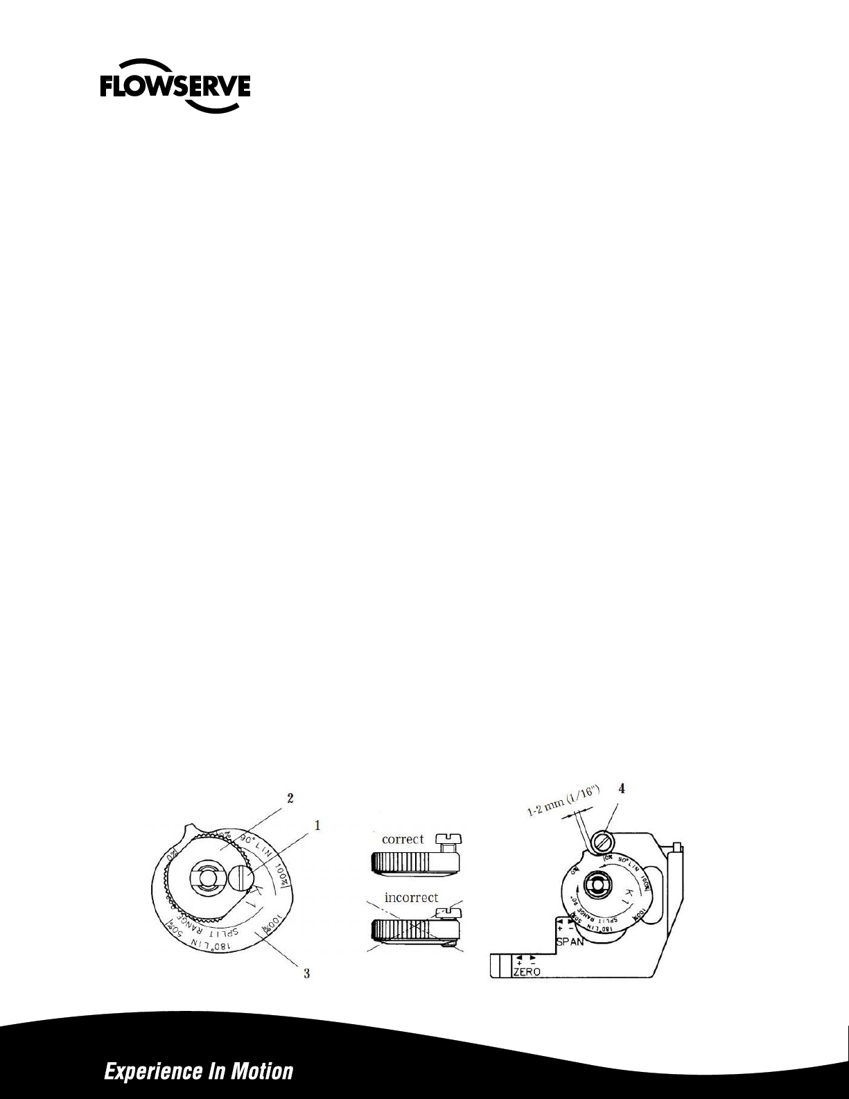
Cam Adjustment:
1. Remove cover and indicator.
2. Loosen the screw (1) and turn the cam locking nut (2) counter-clockwise until the cam loosens.
3. Adjust the cam (3) as desired making sure that the ball bearing (4) is riding on an active lobe on the cam.
4. To secure the cam, make sure that the screw (1) is backed out form the locking nut (2) then finger tighten the
locking nut and tighten screw (1).
5. Install and adjust the indicator and re-install cover.
Page 3
3
Calibration Procedure:
1. Apply 0% input signal (0% = 20 kPa, 3 psi, or 4 mA).
2. Wait for steady state. It is important to wait for steady state. On very large actuators, it can take minutes to
establish.
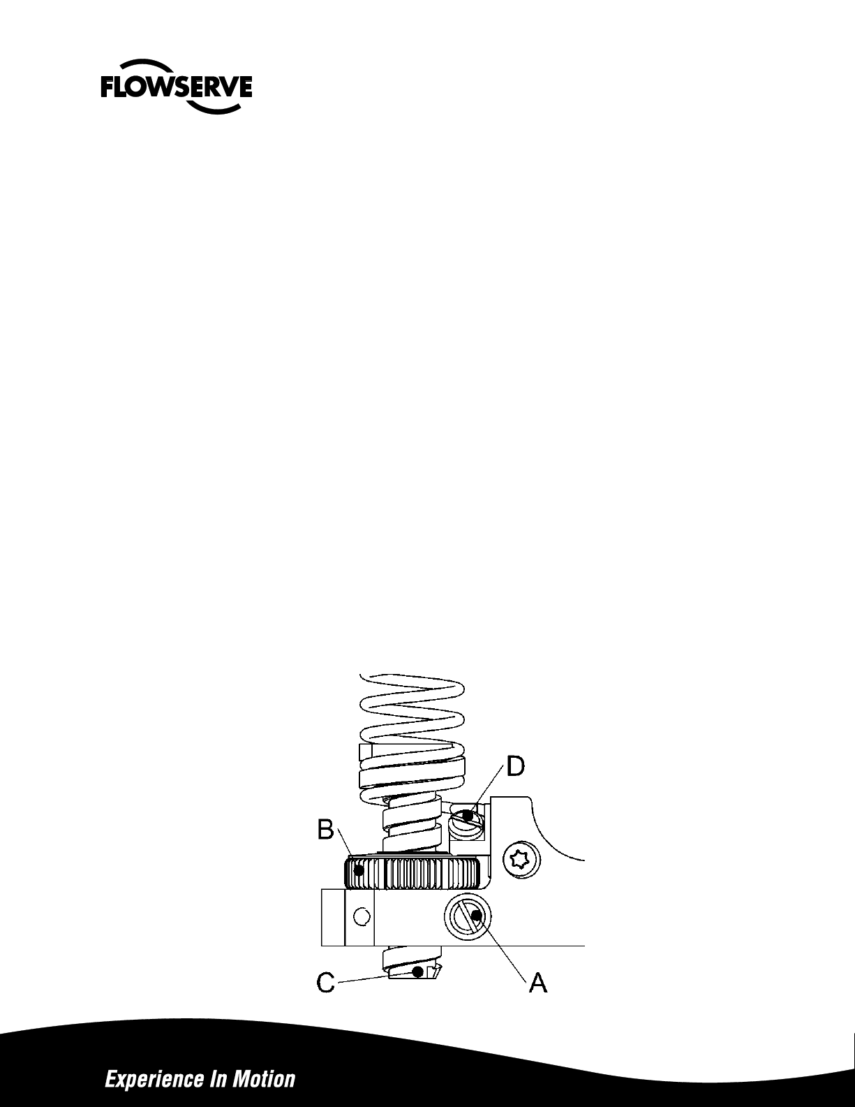
3. Loosen locking screws A and D by about 1 turn. Locking screw D is the angled screw, just above and to the right
of the Zero thumbwheel. If the locking screws are excessively loose, you risk introducing unwanted movement.
4. Adjust “ZERO” position using thumbwheel B. You may find it convenient to turn the thumbwheel by using a
screwdriver blade in the slots.
If using a spring-return actuator, the zero point should be the point at which the positioner output pressure is
still zero, but just begins to increase on any tiny increase of signal. This enables all available spring forces to
be applied to move the valve to its safe position.
If using a double-acting actuator, the zero point is the point at which the actuator will move on any signal
increase.
If the valve jumps upscale on the initial incremental signal change, the cam is likely misaligned. See page 2
for cam alignment instructions. Revivify cam alignment, then recheck the zero adjustment
4b.Retighten locking screw D to lock the Zero Nut. DO not retighten A at this time
5. Apply 100% input signal (100% = 100 kPa, 15 psi, or 20 mA).
6. Wait for steady state.
7. Adjust the “SPAN” setting by turning screw C with a flat-blade screwdriver. This adjustment is accessed by
removing the rubber plug in the bottom of the case. The valve should stroke to 100% of desired travel, but
should not be loaded against a mechanical stop. Slightly decrease the signal to verify that the valve is tracking
the signal value. Span is calibrated when the valve strokes to 100% at exactly 100% signal:
8. Lock the calibration mechanism in place by tightening locking screw A.
9. Apply 0% signal and verify zero position. Recalibrate if necessary.
Page 4
4
Cam Installation:
Introduction: The standard cam (labeled “K1” features linear, 90 degree operation for full 3-15 psi input, 3-9 and 9-15 psi
split ranges, and 3-15 psi 180 degree operation. The factory setting is 3-15 psi, 90 degrees, with “D: (direct) side up for full
clockwise position at 3 psi for 90 degree operation.
Caution: Be sure supply air pressure is removed and no pressure exists in the actuator before adjusting cam.
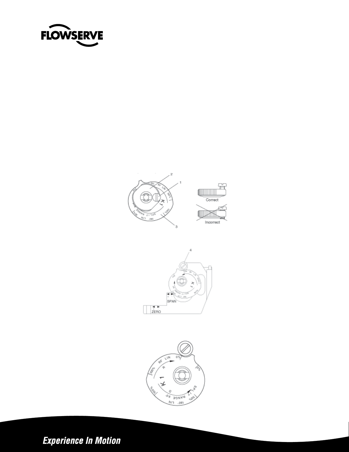
Cam Adjustment/Replacement:
1. Remove cover and indicator.
2. Loosen the cam lock screw (1) and turn the cam locking nut (2) counter-clockwise until the cam is loose. It may
be necessary to brace the output shaft while loosening the cam locking nut.
3. Adjust the cam (3) as desired, making sure that the cam follower (4) always rides on an active lobe on the cam.
4. Secure the cam by finger tightening the cam locking nut (2) and then tighten the cam lock screw (1) see below
Figure below shows cam setting for Direct Action increasing signal 0-100% (20 – 100 kPa, 3-15 psi) to open. Cam
follower to ride on lobe D, 0-100%
Figure below shows cam setting for reverse action, decreasing signal 100 – 0% (100 – 20 kPa, 15-3 psi) to open. Flip
cam over, cam follower to ride on lobe R, 0-100%
Page 5

5
Split Range lobe is used to achieve high resolution in split range applications, where only a portion of the signal is
used to obtain 90 degrees valve travel. For example, to operate 0 to 90 degrees rotation with 0-50% input signal (20 –
60 kPa, 3-9 psi), adjust cam follower to ride on Split Range 0-50% lobe D. Note: to obtain reverse action, flip cam
over and use lobe R.
Spool Valve Installation:
To change out or inspect spool valve, air supply to the positioner must be removed.
To remove spool valve:
1. Remove screw (1).
2. Carefully lift out entire spool valve assembly (2), disengaging spool (3) from balance arm (5).
To maintain highest performance, do not mix spool and block. Do not lubricate valve.
To Install new spool valve:
1. Check that O-rings are in place.
2. Insert spool valve assembly (2), making sure that the leaf spring (4) and balance arm (5) engage the slot in spool
(6).
3. Tighten screw (1).
4. Check for smooth operation of assembly.
I-P Installation:
All I-O modules are factory calibrated an cannot be adjusted. Kits are available to allow easy field installation of
various input options. Kits include modules, mounting hardware, fasteners, and O-rings.
1. Disconnect signal and supply air from positioner.
2. Remove Plug (1) from positioner housing.
3. Make sure O-rings (2) are seated correctly in I-P housing.
4. For weatherproof or intrinsically-safe I-P module, remove cover (4) to allow access to third mounting screw (5).
5. Attach I-P module (3) to positioner housing with three mounting screws (5) provided.
Page 6

6
Model
Agency Approvals
Hazardous Location
Rating1
Max Voltage
(vdc)
Min. Voltage
(vdc)
Max. Current
(mA)
W7000
None
None
N/A
N/A
N/A
W7100
None
None
30 vdc
6 vdc
150 mA
W7200
FM
CSA
ATEX/IECEx
(EX) Cl. I Div 1, Gr. B-D
(EX) Cl. I Div. 1 Gr. B-D
(EX) Ex d IIC T4-T63
30 vdc
30 vdc
30 vdc4
6 vdc
6 vdc
6 vdc
150 mA
150 mA
50 mA4
W74002
FM
CSA
ATEX/IECEx
(IS) Cl. I Div. 1 Gr. A-D
(IS) Cl. I Div. 1 Gr. A-D
(IS) Ex ia IIC T63
28 vdc4
28 vdc4
30 vdc4
6 vdc
6 vdc
6 vdc
50 mA4
50 mA4
110 mA4
W7500
None
None
30 vdc
6 vdc
30 mA
W7600
None
None
N/A
N/A
N/A
Electrical Specifications
Warning: These instruments must be installed in accordance with local national electrical codes, especially for hazardous
locations. Consult unit label to determine specific unit certifications.
Notes:
1 See hazardous location certificate for detailed temperature ratings. All Apex W7000 units comply with ATEX
directive for non-electric equipment intended for use in hazardous locations to Ex II 2 G.
2 Additional information regarding entity parameters and instructions for wiring to intrinsically-safe I-P may be found
in separate IOM, as well as in the hazardous location certificate.
3 See hazardous location certificate for special conditions for safe use.
4 Maximum voltage and current considerations may be affected by application specifics, such as choice of barrier,
ambient temperatures, etc. See hazardous location certificate for additional information.
Page 7

7
Filter Plug Replacement:
Caution: Do not operate the unit without filter and filter plug installed. Do not attempt to unscrew filter plug while
positioner is pressurized.
Note: This filter is not designed to act as a permanent source of clean, dry air.
1. Remove air supply pressure from positioner.
2. Unscrew filter plug (1) and O-ring.
3. Remove filter (3) and inspect filter and filter compartment. If moisture is found, check upstream filters and oilwater separators. Moisture can cause I-P failure.
4. Replace filter if necessary and reinstall.
Maintenance:
The Apex W7000 positioner is designed for long life and trouble-free operation. The following steps should be
followed every six months to assure proper operation.
1. Check air supply and associated filtration equipment. See “Supply Air Requirements.”
2. Make sure arms, bearings, and adjustment screws move freely. Caution: Moving parts to check freedom with
supply pressure connected will cause rotation of cam. Be sure to keep fingers away from cam pinch points. If
parts do not move freely disassemble and lubricate with a light, instrument grade grease (Lubriplate MAG 1 or
equivalent).
3. Check for smooth operation of the spool valve. If it sticks or feels “gummy”, remove and clean both spool and
valve bore with solvent. Make sure both parts are clean and dry before reinstalling. Do NOT apply grease to
these parts.
4. Check for air leaks in air supply.
5. Refer to “Troubleshooting” sections if maintenance does not cure problem.
Page 8

8
SPARE PARTS APEX W7000
DWG
FLS
Description
Qty
No
p/n
1
Housing
N/A
2
X01370
Front cover incl. O-ring and screws
1 3 X01371
Connecting block NPT 1/4" assembly
1
3
X01372
Connecting block G 1/4" assembly
1
4
X01373
Relief valve spring Set of 5 pcs
1
6
X01374
Gasket W7000
1
Page 9

9
6
X01375
Gasket W7100
1
7
X01376
Diaphragm cover incl. O-ring
1
8
X01377
Diaphragm
1
9
X01378
Diaphragm washer
2
10
X01379
Balance arm
1
13
X01380
Feedback spring 3-15 psi assembly
1
13
X01381
Feedback spring 6-30 psi assembly
1
18
X01382
Lower arm assembly
1
19
X01383
Rod
1
20
X01384
Spring
1
21
X01386
Indicator flat, green/black
1
22
X01389
Indicator cover flat for flag incl. O-ring
1
22
X01390
Indicator cover Blind
1
XK0296
Indicator "Flat" assy
1
22
XK0297
Dome indicator "Pharos" assy
1
24
X01391
Twist stop
1
25
X01433
Pilot valve incl. O-rings
1
25
X01444
Pilot valve P5 assembly, low-bleed
1
26
X01393
Shaft incl. O-rings, screw
1
27
X01394
Cam locking nut incl. screw
1
29
X01395
Zero cover
1
30
X01396
Cover
1
31
X01397
Mounting adapter incl. screws
1
32
X01398
Ball bearing
1
35
X01399
Identification cover 90 deg scale (for flat indicator)
1
36
X01406
Identification cover no scale (for Pharos indicator)
1
36
X01400
Plug NPT 1/8" Set of 25 pcs
1
36
X01401
Plug 1/8" G Set of 25 pcs
1
37
X01437
Cam K1 90°/180° Linear 0-100%, split range 0-50-
100%
1
37
X01438
Cam K3 30°/60° Linear 0-100%, split range 0-50-
100% 1 37
X01411
Cam K8 90° =% and SQR 0-100%,
1
38-45, 75-80
X01403
Screw set A2/A4 P5/EP5
Set
46-53, 70, 81
X01404
Seal and O-ring set NBR, Nitrile rubber
W7000/W7100
Set
46-53, 70, 81
X01405
Seal and O-ring set Q, silicon rubber
W7000/W7100
Set
54
X54519
Spindle adaptor (Consult Flowserve)
1
61
I/P housing base
N/A
62
X01408
I/P cover incl. screws
1
63
X01409
I/P nose NPT 1/4" assembly
1
63
X01410
I/P nose G 1/4" assembly
1
64
X01373
Relief valve spring Set of 5 pcs
1
65
X01412
Filter plug assy. incl. filter and O-ring
1
66
X01413
Filters (5 pcs)
Set
67
X01414
Gasket I/P
1
70
KM71
I/P converter general purpose
1
82
KM72
I/P converter explosionproof
1
83
KM75
I/P converter fail-in-place
1
Page 10

10
APEX W7000 SYSTEM
-I/P CONVERTERS
-DOME INDICATOR
-GAUGES
-SWITCHBOXES
Page 11

11
DIMENSIONS:
Page 12

12
Bulletin FCD WCENIM2077-01
Flowserve Corporation
1978 Foreman Drive
Cookeville, Tennessee, USA, 38501
931 432-4021
Flowserve Flow Control UK Ltd
Haywards Heath, West Sussex, Uk
44 (0)1444 314400
Flowserve Corporation
12 Tuas Avenue 20
Singapore
68798900
Flowserve Corporation
Rua Tocantins, 128
São Caetano do Sul, SP, Brazil
55 11 2169-6300
Flowserve PMV
Korta Gatan 9
Solna, Sweden 171 54
468 555 10600
To find your local Flowserve representative please
use the Sales Support Locator System found at
www.flowserve.com
Or call toll free: 1-931-432-4021
Flowserve Corporation has established industry leadership in the design and manufacture of its products. When properly selected, this
Flowserve product is designed to perform its intended function safely during its useful life. However, the purchaser or user of Flowserve products
should be aware that Flowserve products might be used in numerous applications under a wide variety of industrial service conditions. Although
Flowserve can provide general guidelines, it cannot provide specific data and warnings for all possible applications. The purchaser/user must
therefore assume the ultimate responsibility for the proper sizing and selection, installation, operation, and maintenance of Flowserve products.
The purchaser/user should read and understand the (INSERT OFFICIAL USER INSTRUCTION TITLE) instructions included with the product,
and train its employees and contractors in the safe use of Flowserve products in connection with the specific application.
While the information and specifications contained in this literature are believed to be accurate, they are supplied for informative purposes only
and should not be considered certified or as a guarantee of satisfactory results by reliance thereon. Nothing contained herein is to be construed
as a warranty or guarantee, express or implied, regarding any matter with respect to this product. Because Flowserve is continually improving
and upgrading its product design, the specifications, dimensions and information contained herein are subject to change without notice. Should
any question arise concerning these provisions, the purchaser/user should contact Flowserve Corporation at any one of its worldwide operations
or offices.
For more information about Flowserve Corporation, contact www.flowserve.com or call USA 1-800-225-6989.
Representative:
 Loading...