

Page 1
VZ 10
Installation Instructions 810748-00
Pneumatic Rail Hook VZ 10
1
Page 2

Contents
Page
Important Notes
Safety Note .....................................................................................................................7
Danger ............................................................................................................................ 7
Explanatory Notes
Description ......................................................................................................................8
Function .......................................................................................................................... 8
Danger ............................................................................................................................ 8
Design .............................................................................................................................8
Technical Data .................................................................................................................9
Wiring
Key ................................................................................................................................10
Wiring Diagram ............................................................................................................. 11
Operation
Danger ..........................................................................................................................12
Tools ..............................................................................................................................12
Annex
Spare Parts ...................................................................................................................13
2
Page 3
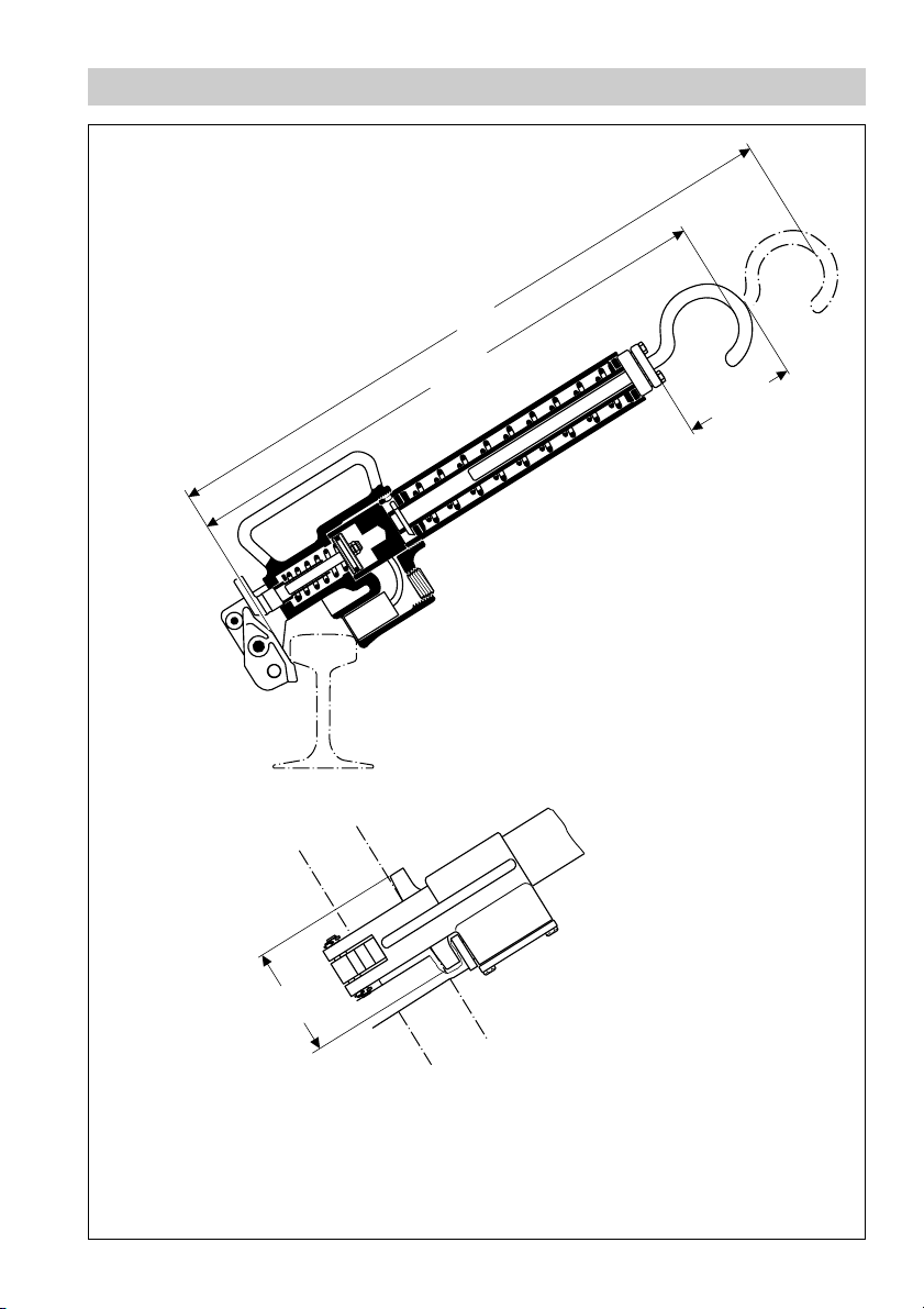
Dimensions
615
540 ± 5
135 ± 5
Fig. 1
100
3
Page 4
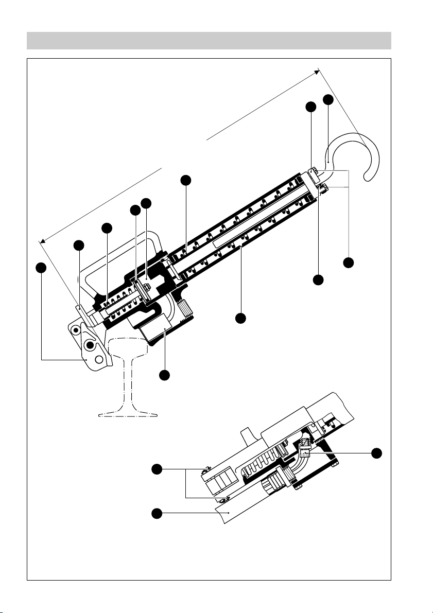
Functional Elements
E
D
C
B
A
540 – 650 mm
F
H
G
I
J
V
Fig. 2
4
K
N
M
L
Page 5
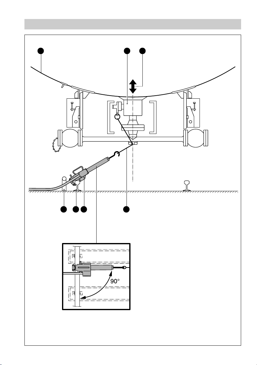
Function
O
P Q
RSTU
Fig. 3
5
Page 6

Key
A
Nose
B
Push rod
C
Compression spring
O-ring
D
Compressed air cylinder
E
Spring for compensating the height variation
F
G
Washer
H
Hook for attaching to the cable
Hexagon screws M 8 x 20
I
Ring
J
Proximity switch
K
Protective hose
L
Split pin
M
Compressed air hose with rapid-action threaded coupling
N
O
Tank of the tank car
P
Rapid-action bottom valve
Q
Height variation
R
Cable as per DIN 26 026
S
VZ 10
T
Rail
U
Auxiliary device (consisting of a tube, ∅ 63 mm)
V
Tube
6
Page 7

Important Notes
Safety Note
Do not use the pneumatic rail hook VZ 10 for any purpose other than keeping the
bottom valves of tank cars open. The device may only be installed by qualified staff.
“Qualified staff” are those persons who have achieved a recognised level of
competence appropriate to the installation and commissioning of this critical safety
device.
Danger
When the rail hook is released, there is a danger of injury to the legs and
feet.
7
Page 8

Explanatory Notes
Scope of Supply
VZ 10
1 Rail hook
1 Installation instructions
Description
According to TRB 851 Paragraph 4.2.5.3, loading plants for combustible gases in
the region of storage facilities with a capacity exceeding 30 t must be equipped with
an emergency shut-down system. In the emergency shut-down system and in other
dangerous situations, the rail hook VZ 10 serves as the safety link between the
loading plant and the tank car. To ensure reliable functioning, there are two necessary
prerequisites:
■ The hydraulic or mechanical equipment of the tank car’s bottom valve must be
equipped with a cable as per DIN 26026 or UIC 573.
■ The rail on which the tank car is standing must have a cross-section corresponding
to DIN 5902 type S-49. If this is not the case, the rail hook can be attached to the
auxiliary device .
Function
During the loading and unloading process, the rail hook VZ 10 is stretched between
the cable and the rail (see Fig. 3) and keeps the bottom valves open. The compressed
air supply is not used to open the bottom valves – it only serves the purpose of
applying a compressive force to the compression spring . The spring for
compensating height variations prevents the rail hook from being torn off the rail
during emptying of the tank car. The proximity switch triggers the emergency shutdown system if the rail hook comes off the rail because of unintentional movement of
the tank car.
U
C
K
F
Danger
Only dry instrument air may be used.
There is a danger of ice formation in the compressed air cylinder.
Design
VZ 10
■ Rail hook with pneumatic control and proximity switch.
8
Page 9

Explanatory Notes – continued –
Technical Data
Control air
Pressure min. 3 bar
Pressure max. 10 bar
Length of compressed air hose and sensor cable
6 m
Response temperature of fire protection system
150 °C
Holding force of rail hook
350 N
Release of rail hook
Tank car movement distance
Materials of the casing
External parts bronze/brass (spark-proof).
Weight
Approx. 5.3 kg
Proximity switch
Type (Pepperl & Fuchs) NJ 10-30 GK-N NJ 10-30 GK-SN
Rated voltage 8 V 8 V
Current consumption
Active surface exposed ≤ 3 mA ≤ 3 mA
Active surface covered ≤ 1 mA ≤ 1 mA
Permissible ambient temperature –25 °C to +100 °C –40 °C to +100°C
Protection IP 68 to DIN 40050 IP 68 to DIN 40050
≤ 500 mm
9
Page 10

Wiring
VZ 10
Install the proximity switch in accordance with the wiring diagram.
Key
1
Power input
2
On
3
Off
Control
4
Ready for operation
5
Wire break
6
Air on
7
Pump on
8
Wire break monitoring
9
Limit-switch signal
10
Air valve
11
K
10
Page 11

Wiring – continued –
Wiring Diagram
11
10
9
3
3
2
8
7
6
5
2
8
7
4
Fig. 4
1
11
Page 12

Operation
1. If rail type is not S-49: Install an auxiliary device consisting of a tube, ∅ 63 mm
U
. Fig. 3
2. Push back the push rod and position the nose so that it is at right angles to
the longitudinal axis of the rail hook.
3. Via the compressed air hose , apply compressed air to the cylinder at a
pressure in the range 3 bar to 10 bar.
Insert the hook in the eye of the cable, and pull the rail hook towards yourself.
H
Before the rail hook is attached to the rail, the distance between the washer and
the tube should be approximately 40 to 50 mm.
V
4. If the distance is greater than 50 mm, the hook must be adjusted so that the
distance described is achieved.
5. To adjust the hook , undo the hexagon screws M 8 and either pull the hook
out or push it in.
6. Tighten the hexagon screws , and use the rail hook as described in 3.
7. After the end of the loading process, remove the rail hook from the rail by hand.
The bottom valves close at the same time.
Danger
Switching off the compressed air after the end of the loading process
produces a very high risk of injury due to the rail hook flying off the rail.
Similarly, during this operating step there is a risk of breakage of the rail
hook.
B A
N
H
H I H
I
E
G
Tools
■
Open-end spanner, 13 mm A.F.
12
Page 13

Annex
Spare Parts
Part
A
B
C
D
G
H
J
K
L
M
N
Part No. Name Stock code
3 Nose, 2.0975.01 048417
2 Push rod, complete, 2.0401 079739
6 Compression spring, 1.4310 079756
7.3 O-ring 34, 52 x 3, 53, Busak + Luyken, NBR 079759
9.80 Washer, 2.0401 079745
9.10 Hook, 2.0401 079752
9.7 Ring, split, PA 043420
10 Proximity switch NJ10-30GK-SN 079757
or
proximity switch NJ10-30GK-N 079851
Pepperl & Fuchs
11.6 Compressed air hose DN 19, DIN 73411, 079763
rubber with fabric insert
4.4 Split pin 4 x 20 DIN 94, brass 013993
11.3 Rapid-action threaded coupling CK-1/4-PK-6-Festo, AL 079761
13
Page 14

141516
Page 15

Page 16

GESTRA Gesellschaften · GESTRA Companies · Sociétés GESTRA · Sociedades Gestra · Società GESTRA
Vertretungen weltweit · Agencies all over the world · Représentations dans le monde entier · Representaciones en todo el mundo · Agenzie in tutto il mondo
España
GESTRA ESPAÑOLA S.A.
Luis Cabrera, 86-88
E-28002 Madrid
Tel. 0034 91/ 5152032
Fax 003491/4136747; 5152036
E-mail: gestra@gestra.es
Polska
GESTRA POLONIA Spolka zo. o.
Ul. Schuberta 104, P. O. Box 71
PL-80-172 Gdansk
Tel. 00 48 58/ 306 1002 oder 306 1010
Fax 00 48 58/ 306 1003 oder 306 33 00
E-mail: gestra@gestra.pl
France Portugal
Flowserve Flow Control S.A. S.
10 Avenue du Centaure, BP 8263
F-95801 CERGY PONTOISE CEDEX
Tél. 0 03 31/ 344326 60
Fax 00331/34432687
E-mail: gnation@flowserve.com
Flowserve Portuguesa, Lda.
Av. Dr. Antunes Guimarães, 1159
Porto 4100-082
Tel. 0035122/6198770
Fax 003 51 22/ 61075 75
E-mail: gestra@gestra.pt
Italia
Italgestra S.r.l.
Via Carducci 125
l-20099 Sesto San Giovanni (MI)
Tel. 0039 02 / 2410 12.1
Fax 00 39 02/ 2410 12.460
E-mail: info@italgestra.it
®
GESTRA GmbH
Postfach 1054 60
D-28054 Bremen
Münchener Str. 77
D-28215 Bremen
Tel. + 49 (0) 421 35 03-0
Fax + 49 (0) 421 35 03-393
E-mail
gestra.gmbh@flowserve.com
Internet www.gestra.de
A Unit of Flowserve Corporation
810748-00/1102c · © 1997 GESTRA GmbH · Bremen · Printed in Germany
 Loading...