

Page 1
USER INSTRUCTIONS
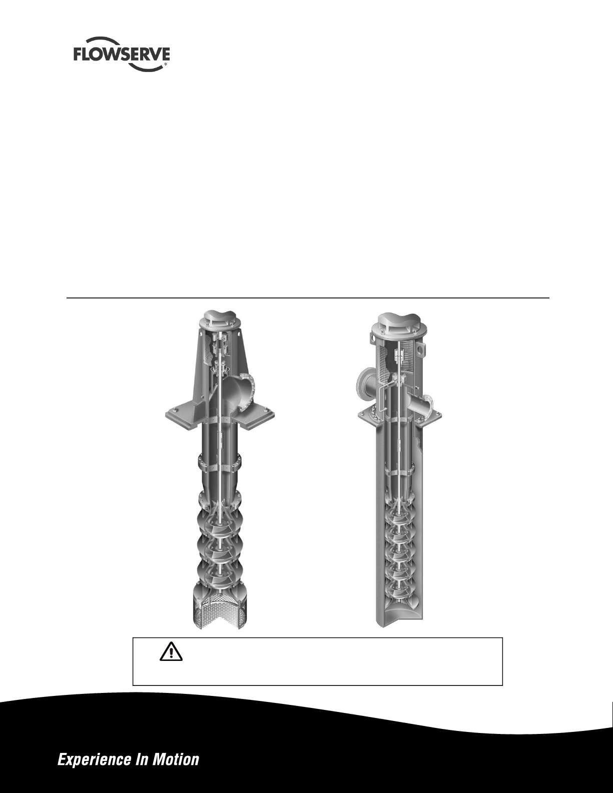
Vertical Turbine Pumps
Wet Pit (VTP)
Double Casing (VPC)
E, S and A series VTPs in wet pit and suction barrel designs
ranging in sizes from 50 mm (6 in.) to 1300 mm (52 in.) with
a single or multiple stages. (This manual does not cover
VTPs fitted with thrust bearing assemblies and VTPs built
for cryogenic service).
PCN=71569224 10-13(E), Based on VTP-QS-0896 Original
Instructions
Installation
Operation
Maintenance
These instructions must be read prior to installing,
operating, using and maintaining this equipment
Page 2

VERTICAL TURBINE PUMPS (VTPS) CENTRIFUGAL PUMPS ENGLISH 71569224 – 10-13
CONTENTS
PAGE
1
INTRODUCTION AND SAFETY ....................... 4
1.1 General ............................................................ 4
1.2 CE Marking and Approvals .............................. 4
1.3 Disclaimer ........................................................ 4
1.4 Copyright ......................................................... 4
1.5 Duty Conditions ............................................... 4
1.6 Safety .............................................................. 5
1.7 Safety Labels Summary .................................. 8
1.8 Specific Machine Performance ........................ 8
1.9 Noise Level ...................................................... 8
1.10 Specific machine performance ................ 9
2 TRANSPORT AND STORAGE ....................... 10
2.1 Consignment receipt and unpacking ............. 10
2.2 Handling ........................................................ 10
2.3 Lifting ............................................................. 10
2.4 Storage .......................................................... 14
2.5 Recycling and End of Product Life ................ 14
3 DESCRIPTION ................................................ 14
3.1 Configuration ................................................. 14
3.2 Nomenclature ................................................ 16
3.3 Design of Major Parts .................................... 17
3.4 Performance and Operation Limits................ 21
4 INSTALLATION ............................................... 21
4.1 Location ......................................................... 21
4.2 Preparation .................................................... 21
4.3 Foundation ..................................................... 21
4.4 Grouting ......................................................... 23
4.5 Lifting and Assembly ..................................... 24
4.6 Initial Alignment ............................................. 30
4.7 Piping ............................................................. 31
4.8 Electrical Connections ................................... 34
4.9 Final Shaft Alignment Check ......................... 34
4.10 Protection Systems ................................ 34
PAGE
6 MAINTENANCE ............................................... 46
6.1 General .......................................................... 47
6.2 Maintenance Schedule .................................. 47
6.3 Spare Parts .................................................... 49
6.4 Recommended Spares and Consumables .... 49
6.5 Tools Required ............................................... 49
6.6 Fastener Torques ........................................... 50
6.7 Setting Impeller Clearance............................. 51
6.8 Disassembly ................................................... 51
6.9 Examination of Parts ...................................... 51
6.10 Assembly ................................................ 55
7 FAULTS; CAUSES AND REMEDIES ............. 56
8 DRAWINGS AND PARTS LISTS .................... 58
8.1 Cross Section: Product Lubricated VTP ........ 58
8.2 Cross Section: Enclosed Tube VTP ............... 61
8.3 Cross Section: Suction Barrel VTP ................ 64
8.4 General Arrangement Drawing ...................... 67
9 CERTIFICATION .............................................. 67
10 OTHER RELEVANT DOCUMENTATION AND
MANUALS ........................................................ 67
10.1 Supplementary User Instructions ........... 67
10.2 Change Notes ........................................ 67
11 APPENDIX ....................................................... 68
11.1 Bill of Materials Reference Numbers ..... 68
5 COMMISSIONING, STARTUP, OPERATION
AND SHUTDOWN ........................................... 35
5.1 Pre-commissioning Procedure ...................... 35
5.2 Pump Lubricants ........................................... 35
5.3 Impeller Adjustment ....................................... 38
5.4 Direction of Rotation ...................................... 41
5.5 Guarding ........................................................ 41
5.6 Priming and Auxiliary Supplies ...................... 41
5.7 Starting the Pump .......................................... 42
5.8 Operating the Pump ...................................... 45
5.9 Stopping and Shutdown ................................ 46
5.10 Hydraulic, mechanical and electrical duty46
Page 2 of 76 flowserve.com
Page 3

VERTICAL TURBINE PUMPS (VTPS) CENTRIFUGAL PUMPS ENGLISH 71569224 – 10-13
INDEX
PAGE
Alignment of shafting (see 4.3, 4.6 and 4.9)
Assembly (6.10) ....................................................... 55
ATEX marking (1.6.4.2) ............................................. 7
Bill of materials reference numbers (11.1) …….......68
CE marking and approvals (1.2) ................................ 4
Certification (9) ........................................................ 67
Change notes (10.2) ................................................ 67
Clearances, impeller (6.7) ....................................... 51
Commissioning and operation (5) ........................... 35
Compliance, ATEX (1.6.4.1) ...................................... 6
Configurations (3.1) ................................................. 14
Copyright (1.4) ........................................................... 4
Design of major parts (3.3) ...................................... 17
Direction of rotation (5.4) ......................................... 41
Disassembly (6.8) .................................................... 51
Disclaimer (1.3) ......................................................... 4
Dismantling (6.8, Disassembly) ............................... 51
Drawings (8) ............................................................ 58
Duty conditions (1.5) .................................................. 4
Electrical connections (4.8) ..................................... 34
End of product life (2.5) ........................................... 14
Examination of parts (6.9) ....................................... 52
Fastener torques (6.6) ............................................. 50
Faults; causes and remedies (7) ............................. 56
Foundation (4.3) ...................................................... 21
General arrangement drawing (8.4) ........................ 67
General assembly drawings (8) ............................... 58
Grouting (4.4)........................................................... 23
Guarding (5.5).......................................................... 41
Handling (2.2) .......................................................... 10
Hydraulic, mechanical and electrical duty (5.10) ..... 46
Impeller clearance (6.7) ........................................... 51
Inspection (6.2.1 and 6.2.2) ..................................... 48
Installation (4) .......................................................... 21
Lifting (2.3) ............................................................... 10
Location (4.1) ........................................................... 21
Lubrication (5.2) ....................................................... 35
Maintenance (6) ....................................................... 47
Maintenance schedule (6.2) .................................... 47
Name nomenclature (3.2) ........................................ 16
Nameplate (1.7.1) ...................................................... 8
Nozzle loads (4.7.2) ................................................. 31
Operating limits (3.4.1) ............................................ 21
Ordering spare parts (6.3.1) .................................... 49
Parts lists (8) ............................................................ 58
Performance (3.4) .................................................... 21
Piping (4.7) .............................................................. 31
Pre-commissioning (5.1) .......................................... 35
Priming and auxiliary supplies (5.6) ........................ 41
Protection systems (4.10) ........................................ 34
Reassembly (6.10, Assembly) ................................. 55
Receipt and unpacking (2.1) .................................... 10
Recommended spares (6.4) .................................. 499
PAGE
Recycling (2.5) ......................................................... 14
Replacement parts (6.3 and 6.4) ............................. 49
Running the pump (5.8) ........................................... 45
Safety action (1.6.3) ................................................... 5
Safety labels (1.7.2) ................................................... 8
Safety markings (1.6.1) .............................................. 5
Safety, protection systems (see 1.6 and 4.10)
Sealing arrangements (3.3.7) .................................. 19
Sectional drawings (8) .............................................. 58
Setting impeller clearance (6.7) ............................... 51
Sound pressure level (1.9, Noise level) ..................... 8
Spare parts (6.3) ...................................................... 49
Specific machine performance (1.8) .......................... 8
Starting the pump (5.7) ............................................ 42
Stop/start frequency (5.7.8) ..................................... 45
Stopping and shutdown (5.9) ................................... 46
Storage, pump (2.4) ................................................. 14
Storage, spare parts (6.3.3) ..................................... 49
Supplementary manuals or info. sources (10) ......... 67
Supplementary User Instructions (10.1) .................. 67
Thermal expansion (4.6.1) ....................................... 30
Tools required (6.5) .................................................. 49
Torques for fasteners (6.6) ...................................... 50
Trouble-shooting (7) ................................................. 56
Vibration (5.7.7) ........................................................ 44
Page 3 of 76 flowserve.com
Page 4
VERTICAL TURBINE PUMPS (VTPS) CENTRIFUGAL PUMPS ENGLISH 71569224 – 10-13
1 INTRODUCTION AND SAFETY
General
1.1
These instructions must always be kept
close to the product's operating location or
directly with the product.
Flowserve products are designed, developed and
manufactured with state-of-the-art technologies in
modern facilities. The unit is produced with great
care and commitment to continuous quality control,
utilizing sophisticated quality techniques, and safety
requirements.
Flowserve is committed to continuous quality
improvement and being at service for any further
information about the product in its installation and
operation or about its support products, repair and
diagnostic services.
These instructions are intended to facilitate
familiarization with the product and its permitted use.
Operating the product in compliance with these
instructions is important to help ensure reliability in
service and avoid risks. The instructions may not
take into account local regulations; ensure such
regulations are observed by all, including those
installing the product. Always coordinate repair
activity with operations personnel, and follow all plant
safety requirements and applicable safety and health
laws and regulations.
of technical documents and safety instructions. Where
applicable this document incorporates information
relevant to these Directives and Approvals.
To confirm the Approvals applying and if the product is
CE marked, check the serial number plate markings
and the Certification. (See section 9, Certificatio n.)
Disclaimer
1.3
Information in these User Instructions is believed
to be complete and reliable. However, in spite of
all of the efforts of Flowserve Corporation to
provide comprehensive instructions, good
engineering and safety practice should always be
used.
Flowserve manufactures products to exacting
International Quality Management System Standards
as certified and audited by external Quality Assurance
organizations. Genuine parts and accessories have
been designed, tested and incorporated into the
products to help ensure their continued product quality
and performance in use. As Flowserve cannot test
parts and accessories sourced from other vendors the
incorrect incorporation of such parts and accessories
may adversely affect the performance and safety
features of the products. The failure to properly select,
install or use authorized Flowserve parts and
accessories is considered to be misuse. Damage or
failure caused by misuse is not covered by the
Flowserve warranty. In addition, any modification of
Flowserve products or removal of original components
may impair the safety of these products in their use.
These instructions must be read prior to
installing, operating, using and maintaining the
equipment in any region worldwide. The
equipment must not be put into service until all
the conditions relating to safety noted in the
instructions, have been met. Failure to follow
and apply the present user instructions is
considered to be misuse. Personal injury,
product damage, delay or failure caused by
misuse are not covered by the Flowserve
warranty.
CE Marking and Approvals
1.2
It is a legal requirement that machinery and equipment
put into service within certain regions of the world shall
conform with the applicable CE Marking Directives
covering Machinery and, where applicable, Low Voltage
Equipment, Electromagnetic Compatibility (EMC),
Pressure Equipment Directive (PED) and Equipment for
Potentially Explosive Atmospheres (ATEX).
Where applicable the Directives and any additional
Approvals cover important safety aspects relating to
machinery and equipment and the satisfactory provision
Copyright
1.4
All rights reserved. No part of these instructions may
be reproduced, stored in a retrieval system or
transmitted in any form or by any means without prior
permission of Flowserve.
Duty Conditions
1.5
This product has been selected to meet the
specifications of your purchase order. The
acknowledgement of these conditions has been sent
separately to the Purchaser. A copy should be kept
with these instructions.
The product must not be operated beyond
the parameters specified for the application. If
there is any doubt as to the suitability of the
product for the application intended, contact
Flowserve for advice, quoting the serial number.
If the conditions of service on your purchase order
are going to be changed (for example liquid pumped,
temperature or duty) it is requested that the user
seeks the written agreement of Flowserve before
start up.
Page 4 of 76 flowserve.com
Page 5
VERTICAL TURBINE PUMPS (VTPS) CENTRIFUGAL PUMPS ENGLISH 71569224 – 10-13
Safety
1.6
1.6.1
Summary of safety markings
These User Instructions contain specific safety
markings where non-observance of an instruction would
cause hazards. The specific safety markings are:
This symbol indicates electrical safety
instructions where non-compliance will involve a high
risk to personal safety or the loss of life.
This symbol indicates safety instructions where
non-compliance would affect personal safety and
could result in loss of life.
This symbol indicates “hazardous and toxic fluid”
safety instructions where non-compliance would affect
personal safety and could result in loss of life.
This symbol indicates safety
instructions where non-compliance will involve some
risk to safe operation and personal safety and would
damage the equipment or property.
This symbol indicates explosive atmosphere
zone marking according to ATEX. It is used in safety
instructions where non-compliance in the hazardous
area would cause the risk of an explosion.
used in potentially explosive atmospheres
section 1.6.4 also applies.
NEVER DO MAINTENANCE WORK
WHEN THE UNIT IS CONNECTED TO POWER
GUARDS MUST NOT BE REMOVED WHILE
THE PUMP IS OPERATIONAL
DRAIN THE PUMP AND ISOLATE PIPEWORK
BEFORE DISMANTLING THE PUMP
The appropriate safety precautions should be taken
where the pumped liquids are hazardous.
FLUORO-ELASTOMERS (When fitted.)
When a pump has experienced temperatures over
250 ºC (482 ºF), partial decomposition of fluoroelastomers (example: Viton) will occur. In this
condition these are extremely dangerous and skin
contact must be avoided.
HANDLING COMPONENTS
Many precision parts have sharp corners and the
wearing of appropriate safety gloves and equipment
is required when handling these components. To lift
heavy pieces above 25 kg (55 lb) use a crane
appropriate for the mass and in accordance with
current local regulations.
This symbol is used in safety instructions to
remind not to rub non-metallic surfaces with a dry
cloth; ensure the cloth is damp. It is used in safety
instructions where non-compliance in the hazardous
area would cause the risk of an explosion.
This sign is not a safety symbol but indicates
an important instruction in the assembly process.
Personnel qualification and training
1.6.2
All personnel involved in the operation, installation,
inspection and maintenance of the unit must be
qualified to carry out the work involved. If the
personnel in question do not already possess the
necessary knowledge and skill, appropriate training
and instruction must be provided. If required the
operator may commission the manufacturer/supplier
to provide applicable training.
Always coordinate repair activity with operations and
health and safety personnel, and follow all plant
safety requirements and applicable safety and health
laws and regulations.
Safety action
1.6.3
This is a summary of conditions and actions to
prevent injury to personnel and damage to the
environment and to equipment. For products
APPLYING HEAT TO REMOVE IMPELLER
There may be occasions when the impeller has either
been shrunk fit on to the pump shaft or has become
difficult to remove due to products of corrosion.
If you elect to use heat to remove the impeller, it must
be applied quickly to the impeller boss. TAKE
GREAT CARE!
Before applying heat ensure any residual hazardous
liquid trapped between the impeller and pump shaft is
thoroughly drained out through the impeller keyway
to prevent an explosion or emission of toxic vapour.
This must be carried out with the shaft in the vertical
position. On some pump sizes a cavity exists in the
impeller bore so on occasions a significant volume of
liquid may drain out.
THERMAL SHOCK
Rapid changes in the temperature of the liquid within
the pump can cause thermal shock, which can result
in damage or breakage of components and should be
avoided.
HOT (and cold) PARTS
If hot or freezing components or auxiliary heating
supplies can present a danger to operators and
persons entering the immediate area action must be
Page 5 of 76 flowserve.com
Page 6
VERTICAL TURBINE PUMPS (VTPS) CENTRIFUGAL PUMPS ENGLISH 71569224 – 10-13
taken to avoid accidental contact. If complete
protection is not possible, the machine access must
be limited to maintenance staff only, with clear visual
warnings and indicators to those entering the
immediate area. Note: bearing housings must not be
insulated and drive motors and bearings may be hot.
If the temperature is greater than 80 ºC (175 ºF) or
below -5 ºC (23 ºF) in a restricted zone, or exceeds
local regulations, action as above shall be taken.
HAZARDOUS LIQUIDS
When the pump is handling hazardous liquids care
must be taken to avoid exposure to the liquid by
appropriate siting of the pump, limiting personnel
access and by operator training. If the liquid is
flammable and/or explosive, strict safety procedures
must be applied.
Gland packing must not be used when pumping
hazardous liquids.
PREVENT EXCESSIVE EXTERNAL
PIPE LOAD
Do not use pump as a support for piping. Do not
mount expansion joints, unless allowed by Flowserve
in writing, so that their force, due to internal pressure,
acts on the pump flange.
ENSURE CORRECT LUBRICATION
(See section 5, Commissioning, startup, operation
and shutdown.)
START THE PUMP WITH OUTLET
VALVE PARTLY OPENED
(Unless otherwise instructed at a specific point in the
User Instructions.)
This is recommended to minimize the risk of
overloading and damaging the pump motor at full or
zero flow. Pumps may be started with the valve
further open only on installations where this situation
cannot occur. The pump outlet control valve may
need to be adjusted to comply with the duty following
the run-up process. (See section 5, Commissioning
start-up, operation and shutdown.)
NEVER RUN THE PUMP DRY
INLET VALVES TO BE FULLY OPEN
WHEN PUMP IS RUNNING
Running the pump at zero flow or below the
recommended minimum flow continuously will cause
damage to the pump and mechanical seal.
the motor and cause cavitations. Low flow rates may
cause a reduction in pump/bearing life, overheating of
the pump, instability and cavitation/vibration.
Products used in potentially explosive
1.6.4
atmospheres
Measures are required to:
Avoid excess temperature
Prevent build up of explosive mixtures
Prevent the generation of sparks
Prevent leakages
Maintain the pump to avoid hazard
The following instructions for pumps and pump units
when installed in potentially explosive atmospheres
must be followed to help ensure explosion protection.
For ATEX, both electrical and non-electrical
equipment must meet the requirements of European
Directive 94/9/EC. Always observe the regional legal
Ex requirements eg Ex electrical items outside the
EU may be required certified to other than ATEX eg
IECEx, UL.
1.6.4.1
Scope of compliance
Use equipment only in the zone for which it is
appropriate. Always check that the driver, drive
coupling assembly, seal and pump equipment are
suitably rated and/or certified for the classification of the
specific atmosphere in which they are to be installed.
Where Flowserve has supplied only the bare shaft
pump, the Ex rating applies only to the pump. The
party responsible for assembling the ATEX pump set
shall select the coupling, driver and any additional
equipment, with the necessary CE Certificate/
Declaration of Conformity establishing it is suitable for
the area in which it is to be installed.
The output from a variable frequency drive (VFD) can
cause additional heating affects in the motor and so, for
pumps sets with a VFD, the ATEX Certification for the
motor must state that it is covers the situation where
electrical supply is from the VFD. This particular
requirement still applies even if the VFD is in a safe area.
DO NOT RUN THE PUMP AT
ABNORMALLY HIGH OR LOW FLOW RATES
Operating at a flow rate higher than normal or at a flow
rate with no back pressure on the pump may overload
Page 6 of 76 flowserve.com
Page 7
VERTICAL TURBINE PUMPS (VTPS) CENTRIFUGAL PUMPS ENGLISH 71569224 – 10-13
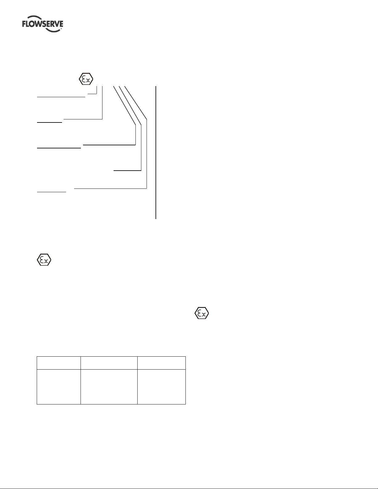
1.6.4.2
Marking
An example of ATEX equipment marking is shown
below. The actual classification of the pump will be
engraved on the nameplate.
II 2 GD c IIC 135 ºC (T4)
Equipment Group
I = Mining
II = Non-mining
Category
2 or M2 = high level protection
3 = normal level of protection
Gas and/or dust
G = Gas
D = Dust
c = Constructional safety
(in accordance with EN13463-5)
Gas Group
IIA – Propane (typical)
IIB – Ethylene (typical)
IIC – Hydrogen (typical)
Maximum surface temperature (Temperature Class)
(see section 1.6.4.3.)
1.6.4.3
Avoiding excessive surface
temperatures
ENSURE THE EQUIPMENT TEMPERATURE
CLASS IS SUITABLE FOR THE HAZARD ZONE
Pumps have a temperature class as stated in the
ATEX Ex rating on the nameplate. These are based
on a maximum ambient of 40 ºC (104 ºF); refer to
Flowserve for higher ambient temperatures.
The surface temperature on the pump is influenced
by the temperature of the liquid handled. The
maximum permissible liquid temperature depends on
the temperature class and must not exceed the
values in the table that follows.
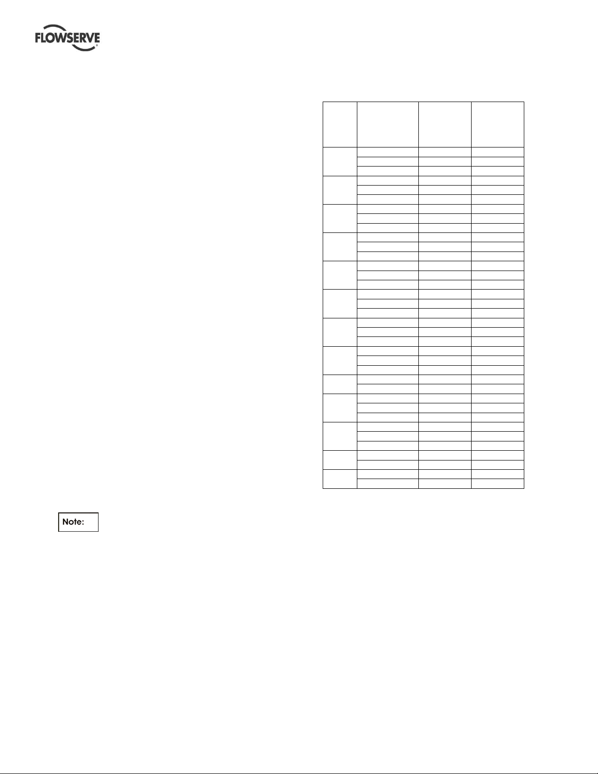
Temperature class
to EN13463-1
T6
T5
T4
T3
T2
T1
* The table only takes the ATEX temperature class into consideration.
Pump design or material, as well as component design or material,
may further limit the maximum working temperature of the liquid.
Maximum surface
temperature permitted
85 °C (185 °F)
100 °C (212 °F)
135 °C (275 °F)
200 °C (392 °F)
300 °C (572 °F)
450 °C (842 °F)
Temperature limit of
liquid handled *
Consult Flowserve
Consult Flowserve
115 °C (239 °F)
180 °C (356 °F)
275 °C (527 °F)
400 °C (752 °F)
The temperature rise at the seals and bearings and
due to the minimum permitted flow rate is taken into
account in the temperatures stated.
The operator is responsible to ensure that the
specified maximum liquid temperature is not
exceeded
Temperature classification “Tx” is used when the
liquid temperature varies and the pump could be
installed in different hazarous atmospheres. In this
case the user is responsible for ensuring that the
pump surface temperature does not exceed that
permitted in the particular hazardous atmosphere.
If an explosive atmosphere exists during the
installation, do not attempt to check the direction of
rotation by starting the pump unfilled. Even a short
run time may give a high temperature resulting from
contact between rotating and stationary components.
Where there is any risk of the pump being run
against a closed valve generating high liquid and
casing external surface temperatures, fit an external
surface temperature protection device.
Avoid mechanical, hydraulic or electrical overload by
using motor overload trips, temperature monitor or a
power monitor and make routine vibration monitoring
checks.
In dirty or dusty environments, make regular checks
and remove dirt from areas around close clearances,
bearing housings and motors.
1.6.4.4
Preventing the buildup of explosive
mixture
ENSURE THE PUMP IS PROPERLY FILLED
AND VENTED AND DOES NOT RUN DRY
Ensure the pump and relevant suction and discharge
pipeline system is totally filled with liquid at all times
during the pump operation, so that an explosive
atmosphere is prevented. In addition it is essential to
make sure that seal chambers, auxiliary shaft seal
systems and any heating and cooling systems are
properly filled.
If the operation of the system cannot avoid this
condition, fit an appropriate dry run protection device
(for example liquid detection or a power monitor).
To avoid potential hazards from fugitive emissions of
vapor or gas to atmosphere the surrounding area
must be well ventilated.
Page 7 of 76 flowserve.com
Page 8
VERTICAL TURBINE PUMPS (VTPS) CENTRIFUGAL PUMPS ENGLISH 71569224 – 10-13
Preventing sparks
1.6.4.5
To prevent a potential hazard from mechanical
contact, the coupling guard must be non-sparking.
To avoid the potential hazard from random induced
current generating a spark, the base plate must be
properly grounded.
Avoid electrostatic charge: do not rub non-metallic
surfaces with a dry cloth; ensure cloth is damp.
For ATEX applications the coupling must be selected
to comply with 94/9/EC. Correct coupling alignment
must be maintained.
Additional requirement for metallic pumps on
non-metallic base plates
When metallic components are fitted on a nonmetallic base plate they must be individually earthed.
1.6.4.6
for which it has been approved to have the correct
corrosion resistance.
Avoid entrapment of liquid in the pump and associated
piping due to closing of suction and discharge valves,
which could cause dangerous excessive pressures to
occur if there is heat input to the liquid. This can occur if
the pump is stationary or running.
Bursting of liquid containing parts due to freezing
must be avoided by draining or protecting the pump
and ancillary systems.
Where there is the potential hazard of a loss of a seal
barrier fluid or external flush, the fluid must be
monitored.
If leakage of liquid to atmosphere can result in a
hazard, install a liquid detection device.
1.6.4.7
AVOID POTENTIAL HAZARDS WHICH GIVE A
RISK OF EXPLOSION
The responsibility for compliance with maintenance
instructions is with the plant operator.
To avoid potential explosion hazards during
maintenance, the tools, cleaning and painting
materials used must not give rise to sparking or
Preventing leakage
The pump must only be used to handle liquids
Maintenance to avoid the hazard
CORRECT MAINTENANCE IS REQUIRED TO
adversely affect the ambient conditions. Where there
is a risk from such tools or materials, maintenance
must be conducted in a safe area.
It is recommended that a maintenance plan and
schedule is adopted. (See section 6, Maintenance.)
Safety Labels Summary
1.7
1.7.1
Nameplate
For details of nameplate, see the Declaration of
Conformity, or separate documentation included with
these User Instructions.
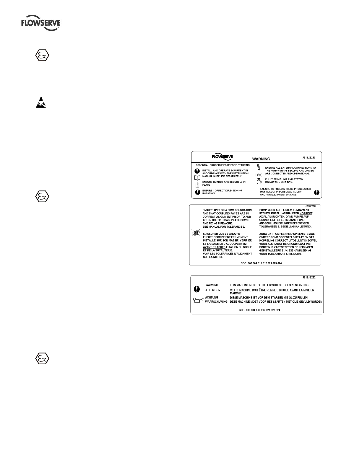
Safety labels
1.7.2
Oil lubricated units only:
Specific Machine Performance
1.8
For performance parameters see section 1.5, Duty
conditions. When the contract requirement specifies
these to be incorporated into User Instructions these
are included here. Where performance data has
been supplied separately to the purchaser these
should be obtained and retained with these User
Instructions if required.
Noise Level
1.9
Attention must be given to the exposure of personnel
to the noise, and local legislation will define when
guidance to personnel on noise limitation is required,
and when noise exposure reduction is mandatory.
This is typically 80 to 85 dBA.
Page 8 of 76 flowserve.com
Page 9
VERTICAL TURBINE PUMPS (VTPS) CENTRIFUGAL PUMPS ENGLISH 71569224 – 10-13
The usual approach is to control the exposure time to
the noise or to enclose the machine to reduce
emitted sound. You may have already specified a
limiting noise level when the equipment was ordered,
however if no noise requirements were defined, then
attention is drawn to the following table to give an
indication of equipment noise level so that you can
take the appropriate action in your plant.
Pump noise level is dependent on a number of
operational factors, flow rate, pipework design and
acoustic characteristics of the building, and so the
values given are subject to a 3 dBA tolerance and
cannot be guaranteed.
Similarly the motor noise assumed in the “pump and
motor” noise is that typically expected from standard
and high efficiency motors when on load directly driving
the pump. Note that a motor driven by an inverter may
show an increased noise at some speeds.
If a pump unit only has been purchased for fitting with
your own driver then the “pump only” noise levels in the
table should be combined with the level for the driver
obtained from the supplier. Consult Flowserve or a
noise specialist if assistance is required in combining
the values.
It is recommended that where exposure approaches
the prescribed limit, then site noise measurements
should be made.
The values are in sound pressure level L
at 1 m
pA
(3.3 ft) from the machine, for “free field conditions
over a reflecting plane”.
For estimating sound power level L
(re 1pW) then
WA
add 17 dBA to the sound pressure value.
The noise levels shown in table 1.9.1 are
extracted from typical motor manufacturer’s
data/catalogue to provide the average expected
motor noise values at no load for reference only and
are not guaranteed. The values could vary
depending upon the test and surrounding conditions.
The combined noise level of the pump and the motor
could exceed the values shown. It is to be noted that
adding motors with similar noise levels increases the
total noise level. Therefore, the dB correction to the
values listed above is required to obtain the
combined noise levels of motor and the pump.
Actual on-site noise measurement by experts is
recommended and safety measures are to be taken
accordingly.
Typical vertical motor noise data (Hollow
1.9.1
and Solid shafts)
Motor
Frame
Size.
NEMA
180 3600 70.0 78.0
210 3600 70.0 78.2
250 3600 75.0 83.4
280 3600 75.0 83.8
320 3600 75.0 84.0
360 3600 75.0 84.2
400 3600 80.0 89.5
440 3600 80.0 90.0
449 1800 85.0 97.8
5000
5800 3600 90.0 103.7
6800 1800 90.0 103.9
8000 1800 90.0 104.7
Specific machine performance
1.10
RPM Sound
Pressure
(dBA )
(WP- I
enclosure)
1800 60.0 68.0
1200 & slower 55.0 63.0
1800 60.0 68.2
1200 & slower 55.0 63.2
1800 70.0 78.4
1200 & slower 60.0 68.4
1800 70.0 78.8
1200 & slower 60.0 68.8
1800 65.0 74.0
1200 & slower 65.0 74.0
1800 65.0 74.2
1200 & slower 65.0 74.2
1800 70.0 79.5
1200 & slower 65.0 74.5
1800 70.0 80.0
1200 & slower 70.0 80.0
1200 & slower 80.0 92.8
3600 90.0 102.8
1800 85.0 97.8
1200 & slower 80.0 92.8
1800 90.0 103.7
1200 & slower 80.0 93.7
1200 & slower 85.0 98.8
1200 & slower 85.0 99.7
Sound
Power
(dBA )
(WP- I
enclosure
For performance, parameters see section 1.5, Duty
conditions. Whenever there is a contract
requirement to incorporate specific machine
performance into User Instructions, those are
included here. In cases where performance data has
been supplied separately to the purchaser, the same
should be retained with these User Instructions, if
required.
Page 9 of 76 flowserve.com
Page 10
VERTICAL TURBINE PUMPS (VTPS) CENTRIFUGAL PUMPS ENGLISH 71569224 – 10-13
A
2 TRANSPORT AND STORAGE
Consignment receipt and unpacking
2.1
Immediately after receipt of the equipment it must be
checked against the delivery and shipping
documents for its completeness and that there has
been no damage in transportation. Any shortage and
or damage must be reported immediately to
Flowserve and received in writing within one month
of receipt of the equipment. Later claims cannot be
accepted.
Check any crates, boxes and wrappings for any
accessories or spare parts which may be packed
separately with the equipment or attached to side
walls of the box or equipment.
Each product has a unique serial number. Check that
this number corresponds with that advised and
always quote this number in correspondence as well
as when ordering spare parts or further accessories.
Handling
2.2
Boxes, crates, pallets or cartons may be unloaded
using fork lift vehicles or slings dependent on their
size and construction.
Do not use the lifting pins at the base
of the discharge head while lifting unassembled cast
discharge heads unless the discharge head is
secured by slings to prevent overturning. Never lift
the completely assembled pump with eyebolts
through this flange.
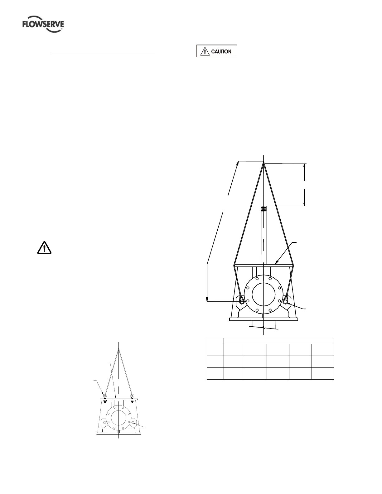
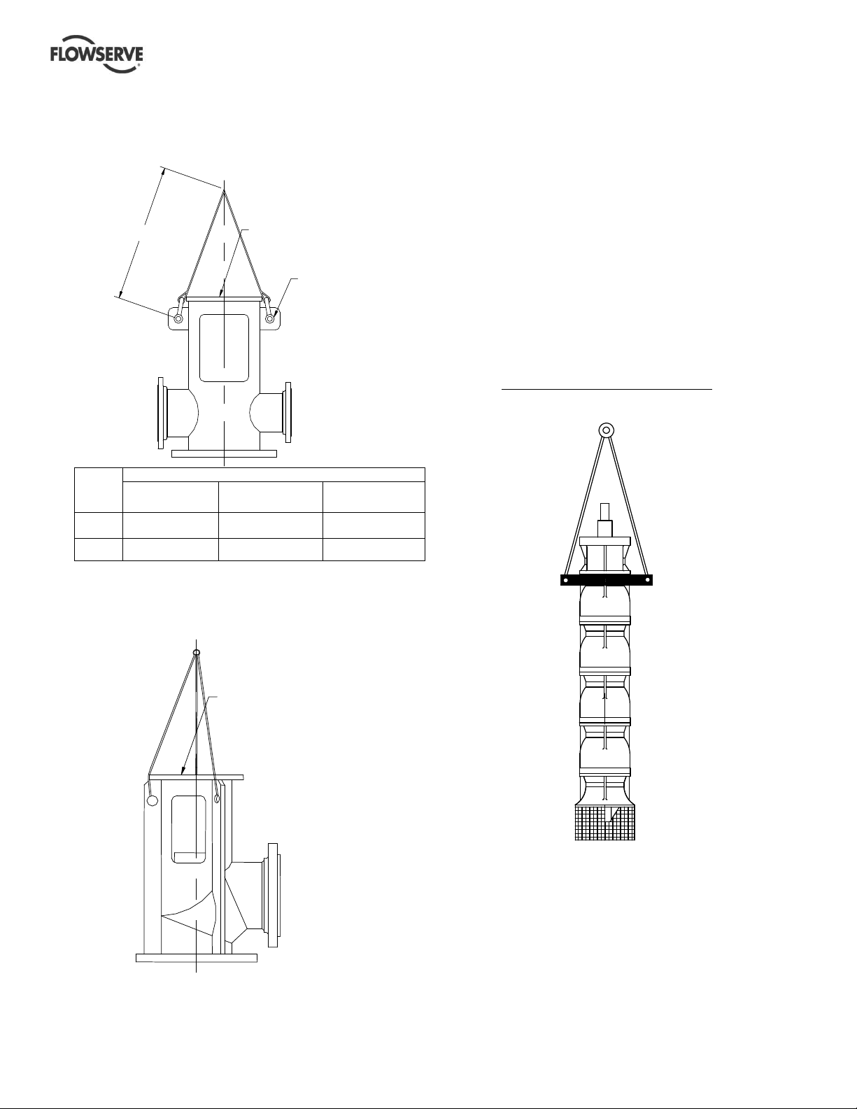
Lifting of type-W cast discharge head with
2.3.2
pump attached
Cast discharge heads with pump attached are
recommended to be lifted by using pins suitable with
that head size (refer to the table shown). The slings
are attached as shown maintaining minimum length
of the sling from the shaft end as shown in the detail.
305 mm (12 in.) MIN.
" L "
Lifting
2.3
Equipment in excess of 25Kg (55lbs) should be
lifted by mechanical means. Fully trained personnel
must carry out lifting, in accordance with local
regulations.
Before lifting the driver alone, refer to the
manufacturer’s instructions.
Lifting of W-type cast discharge head
2.3.1
(head only-pump not attached)
Lift the unassembled cast discharge heads (pump
not attached) by installing eyebolts as shown using
the flange mounting holes. Lower the head over
shaft into place.
CAST HEAD
UNASSEMBLED
EYE BOLTS
PIN
CAST HEAD
WITH PUMP
TTACHED
PIN
Cast heads with discharge size mm (in.)
Dia.
“L” is approximate length
Lifting of fabricated discharge heads with
2.3.3
Pin
L
100
(4)
25
(1)
1220
(48)
150
(6)
32
(1.25)
1370
(54)
200
(8)
32
(1.25)
1370
(54)
250
(10)
32
(1.25)
1520
(60)
300
(12)
38
(1.5)
1520
(60)
or without the pump
If the pump is supplied with a fabricated discharge
head use 2 point or 3 point method of lifting as shown
in the details provided in 2.3.3.1 & 2.3.3.2. This
method is applicable to the lifting of discharge heads
with or without the pump.
Page 10 of 76 flowserve.com
Page 11
VERTICAL TURBINE PUMPS (VTPS) CENTRIFUGAL PUMPS ENGLISH 71569224 – 10-13
2.3.3.1
Two point lifting of fabricated discharge
head types TF, UF & HFH (with or
without pump attached)
"L"
Fabricated heads with discharge size mm (in.)
100-200
(4-8)
Pin
Dia.
Weight <2300 (5000) <4500 (10000) <6800 (15000)
2.3.3.2
32 (1.25) 38 (1.50) 44 (1.75)
Three point lifting of fabricated
FABRICATED WITH
2 POINT LIFTING
50 mm (2in.) HOLE
250-600
(10-24)
700-900
(28-36)
discharge head of type HFL (with or
without pump attached)
Lifting of bowl assembly only
2.3.4
Clamp the bowl assembly and center the lifting hook
for lifting and lowering the assembly into the
sump/suction barrel.
a) Lower the bowl assembly until the clamp
extensions rest on the foundation (use
appropriate supports).
b) Build the very first section of the column piping,
and lower the entire assembly to assemble the
next column section.
c) Continue to build until it is ready for discharge
head assembly.
d) Install the discharge head.
e) Assemble the motor.
Example: Lifting of bowl assembly
HFL STYLE FABRICATED
WITH 3 POINT LIFTING
Page 11 of 76 flowserve.com
Page 12
VERTICAL TURBINE PUMPS (VTPS) CENTRIFUGAL PUMPS ENGLISH 71569224 – 10-13
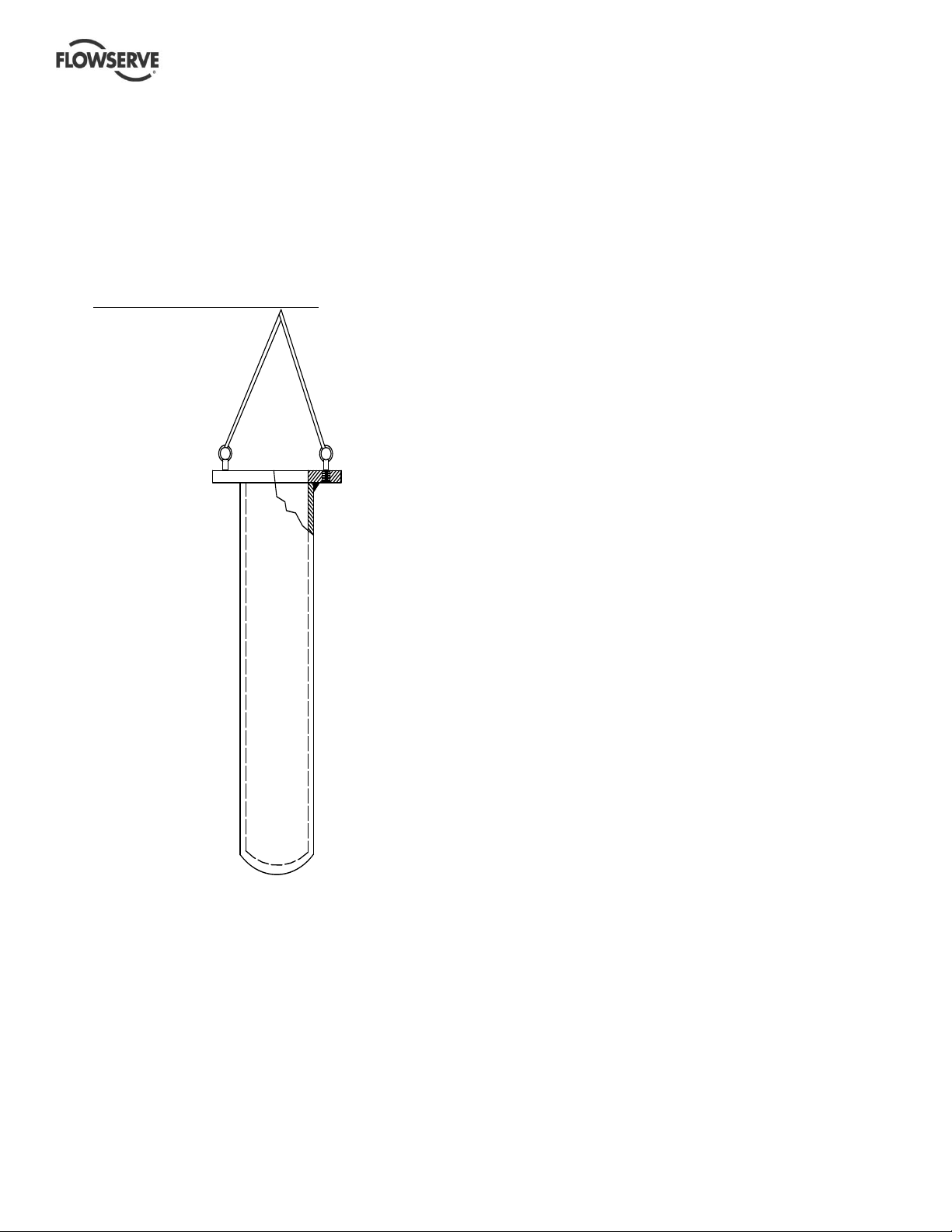
Lifting of suction barrel
2.3.5
Suction barrel (also referred as ‘Can’) is always
supplied separately and has to be installed into the
sump first. Install eyebolts on the flange of the
suction barrel and attach slings and straps to bring
the suction barrel to a vertical position. Move the
barrel for installation. Provide hand support to
prevent the suction barrel from swaying during
movement.
Example: Lifting of suction barrel
SUCTION BARREL (CAN)
Lifting of fully assembled pumps
2.3.6
If the pump is fully assembled, it has to be
adequately strapped and supported at least two
places before it can be lifted from the shipping crate
and moved to the installation site. See details
shown. Same rules are applicable when the pump is
pulled out from the sump and moved to another
location.
Page 12 of 76 flowserve.com
Page 13
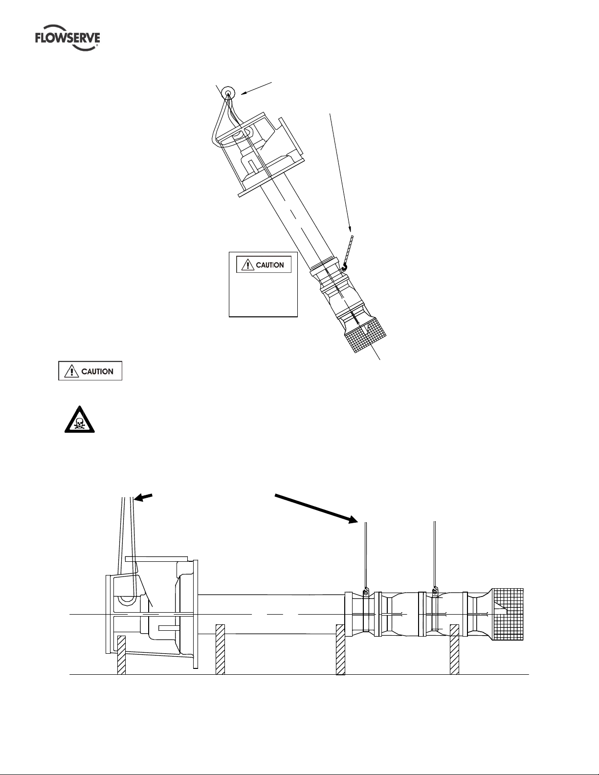
VERTICAL TURBINE PUMPS (VTPS) CENTRIFUGAL PUMPS ENGLISH 71569224 – 10-13
Pump must be supported
at least two places
when lifted.
Do not use chains
to wrap around.
Two (2)
cranes are
required
Examples shown here are for illustration only. See section 2.3 1~2.3.6 for specific lifting
instructions based on design variations. The pumps vary in weight, length and physical appearances from the
types shown here.
Therefore, before lifting is attempted, exercise caution to prevent any injuries or loss of life.
Pump must be supported at
least two places when lifted.
Do not use chains to wrap around.
Page 13 of 76 flowserve.com
Page 14

VERTICAL TURBINE PUMPS (VTPS) CENTRIFUGAL PUMPS ENGLISH 71569224 – 10-13
Storage
2.4
Store the pump in a clean, dry
location away from vibration. Leave piping
connection covers in place to keep dirt and other
foreign material out of pump casing. Turn the pump
at frequent intervals to prevent brinelling of the
bearings and the seal faces, if fitted, from sticking.
Inspection before storage
2.4.1
a) Inspect the preservative coating/painted surfaces
on the various parts. Touch up the areas, If
necessary.
b) Inspect all covers over pump openings and piping
connections. If found damaged, remove the
covers and inspect interiors of the opening for any
deposits of foreign materials or water.
c) If necessary, clean and preserve the interior parts
as noted above to restore the parts to the "as
shipped" condition. Replace covers and fasten
securely.
d) Exercise caution with pumps exposed to weather.
Containers are not leak proof. Parts may be
coated with a residual amount of protective
coating, which will wash away if exposed to
elements.
Short term storage (up to 6 months)
2.4.2
Follow the steps given in section 2.4.1. Select a
storage space so that the unit will not be subjected to
excess moisture, extreme weather conditions,
corrosive fumes, or other harmful conditions.
Driver storage instructions: Check driver
manufacturer’s User Instructions
Long term or extended storage
2.4.3
If a situation arises for a long-term storage, ( more
than 6 months) please contact Flowserve for special
storage instructions and warranty related information.
personal protective equipment is used. The safety
specifications must be in accordance with the current
regulations at all times.
3 DESCRIPTION
Should questions arise concerning the pump,
Flowserve pump division will require the complete
serial number to be of assistance. The serial number
is stamped on a metal nameplate affixed to the
discharge head assembly. The driver will have a
separate nameplate attached to it. If you are
requesting information on the driver, please provide
both the driver serial number and the pump serial
number for Flowserve representative.
Configuration
3.1
VTPs, are engineered pumps as:(a) Wet pit type and
(b) suction barrel (can) type pumps. Most pumps are
built with customer specific features and for
applications such as water pumping stations, deep
wells, storm water service, industrial and cryogenic
applications. The pumps vary in size, impeller types
and length, whether it is an open shaft or enclosed
shaft designs and type of discharge head used.
Recycling and End of Product Life
2.5
At the end of the service life of the product or its
parts, the relevant materials and parts should be
recycled or disposed of using an environmentally
acceptable method and local regulations. If the
product contains substances which are harmful to the
environment, these should be removed and disposed
of in accordance with current regulations. This also
includes the liquids and or gases in the "seal system"
or other utilities.
Make sure that hazardous substances or
toxic fluids are disposed of safely and that the correct
Page 14 of 76 flowserve.com
Page 15
VERTICAL TURBINE PUMPS (VTPS) CENTRIFUGAL PUMPS ENGLISH 71569224 – 10-13
A
Y
A
Y
A
A
A
A
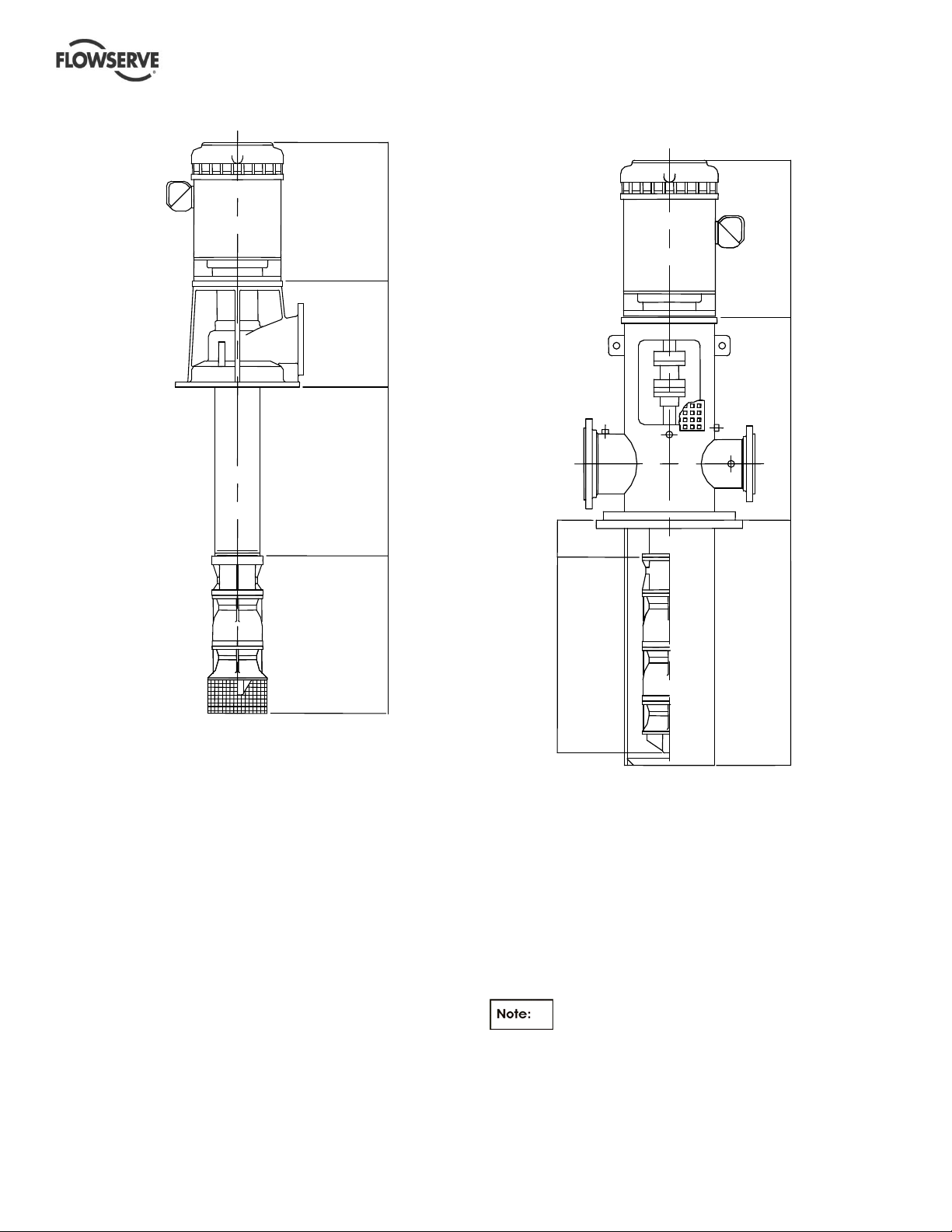
Sump and deep well VTP
3.1.1
DRIVER
DISCHARGE
HEAD
COLUMN
SSEMBL
SSEMBL
Suction barrel (Can) VTP
3.1.2
DRIVER
DISCHARGE
HEAD
SSEMBLY
COLUMN
SSEMBLY
BOWL
SSEMBLY
BOWL
SSEMBLY
SUCTION
BARREL
(CAN)
3.1.3
Most common VTP models
The VTP configurations shown in sec 3.1.1 and 3.1.2
are typical for variety of VTP models with the bowl
assembly types such as EB, EG, EH, EJ, EK, EL,
EM, EN, EP, EQ, SK, SL, SN, SP, SR, ST, & AV.
The impeller models in each of these pumps are
designated separately (see section 3.2 for more
details) and the pump sizes could vary from 150mm
(6 in) to 1300 mm (52 in.). The size expressed is in
terms of nominal bowl diameter and is always in
inches.
Some units will not require a column
assembly. In such cases, the bowl assembly is
connected directly to the discharge head. Vertical
turbine pumps can have single or multiple stages.
Page 15 of 76 flowserve.com
Page 16
VERTICAL TURBINE PUMPS (VTPS) CENTRIFUGAL PUMPS ENGLISH 71569224 – 10-13
Nomenclature
3.2
The pump size/ serial number will be engraved on
the nameplate typically as below: The nameplate is
attached to the discharge head assembly.
Bowl assembly nomenclature
3.2.1
12 E J H-3
Nominal Bowl Diameter-inches
Impeller Type (A or E or S)
A=Axial, E=Enclosed, S=Semi-open
Bowl Model Types
B,J,K,H,L,M,N,P,Q,R,T,V….
Impeller Model Designation
L, M, H, Y…..
No. of Stages
The typical nomenclature above is the general guide
to the VTP configuration description. Identify the
actual pump size and serial number from the pump
nameplate. The driver will have a separate
nameplate attached it.
Discharge head nomenclature
3.2.2
Consists of alphanumeric code as follows.
Examples: 8W16, 10HF20, 6TF16,…….
10 HF 20
Nominal driver base diameter in inches
Discharge head type (see details below)
Nominal discharge diameter in inches
W = Cast head- for horizontal above the ground discharge
HF = Fabricated head for above the ground discharge
TF & LF = Fabricated heads with base flange
UF = Fabricated head for below ground discharge
HFL = Fabricated head for above ground discharge - Low H.P
HFH = Fabricated head for above the ground discharge -High H.P.
Please see section 3.2.2.1 for discharge head types
and identification.
3.2.2.1
Types of discharge heads
Typical discharge head types. Details (a) thru (g).
a) W type cast discharge head
b) HF type fabricated discharge head
(Typically with square base plate)
c) TF type fabricated discharge head
Page 16 of 76 flowserve.com
Page 17
VERTICAL TURBINE PUMPS (VTPS) CENTRIFUGAL PUMPS ENGLISH 71569224 – 10-13
d) LF type fabricated discharge head
(Typically with a circular base plate- ANSI type.
Also available with suction barrel mounting)
e) UF type fabricated discharge head
g) HFH type fabricated discharge head
The discharge heads shown in section
3.2.2.1 (a) thru (g) are for illustration only. The shaft
and coupling arrangements vary. For the actual
configuration of the pump that has been purchased,
please refer to the drawings supplied with the pump
or order specific sectionals from Flowserve.
f) HFL type fabricated discharge head
Design of Major Parts
3.3
Please refer to appendix for Europump part
number equivalents
Drivers
3.3.1
A variety of drivers may be used, however, electric
motors are most common. For the purposes of this
manual, all types of drivers can be grouped into two
categories.
a) Hollow shaft drivers: where the head shaft extends
through a tube in the center of the rotor and is
connected to the driver by a clutch assembly at the top
of the driver.
b) Solid shaft drivers: where the rotor shaft is solid
and projects below the driver-mounting base. This
type driver requires an adjustable coupling for
connecting to the pump.
Discharge Head Assembly
3.3.2
(See also section 3.2.2.1)
The discharge head supports the driver and bowl
assembly as well as supplying a discharge connection
in most cases.
Page 17 of 76 flowserve.com
Page 18
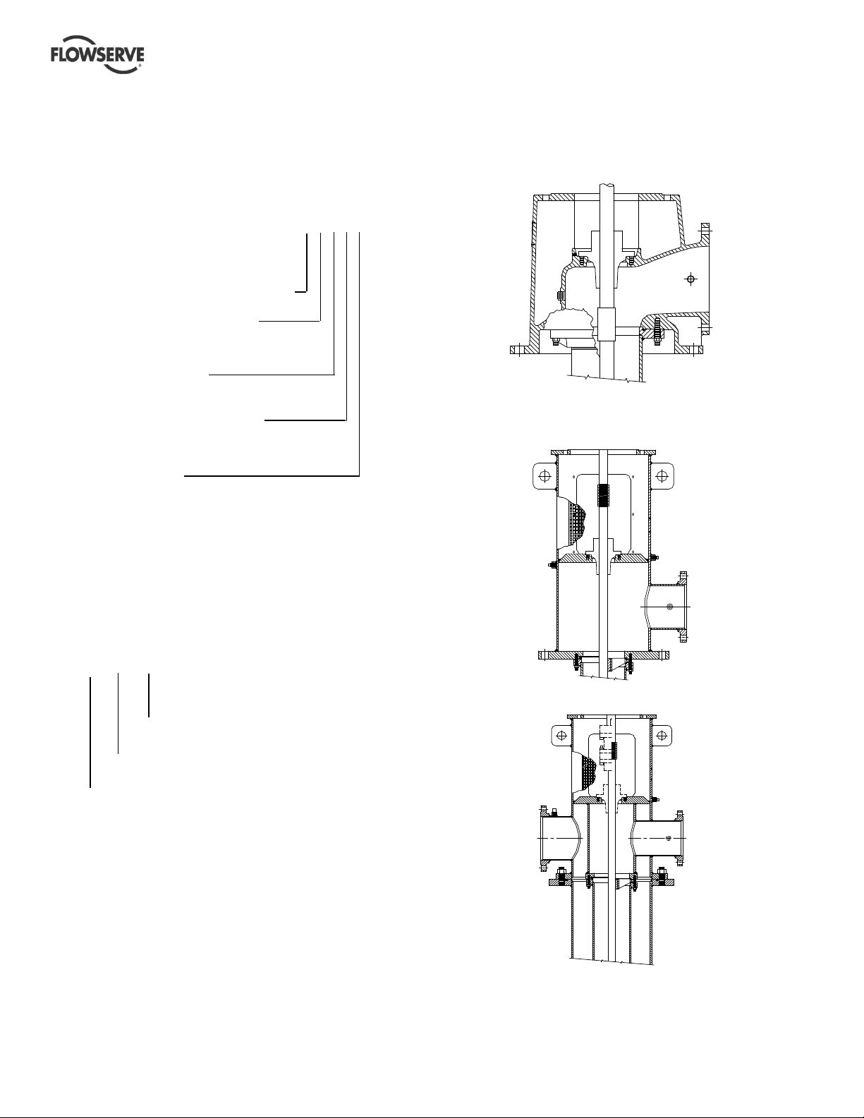
VERTICAL TURBINE PUMPS (VTPS) CENTRIFUGAL PUMPS ENGLISH 71569224 – 10-13
A shaft sealing arrangement is located in the
discharge head to seal the shaft at its exit from the
liquid chamber.
The shaft seal will usually be either a mechanical
seal assembly or stuffing box with an open lineshaft
or a tube-packing box with an enclosed lineshaft.
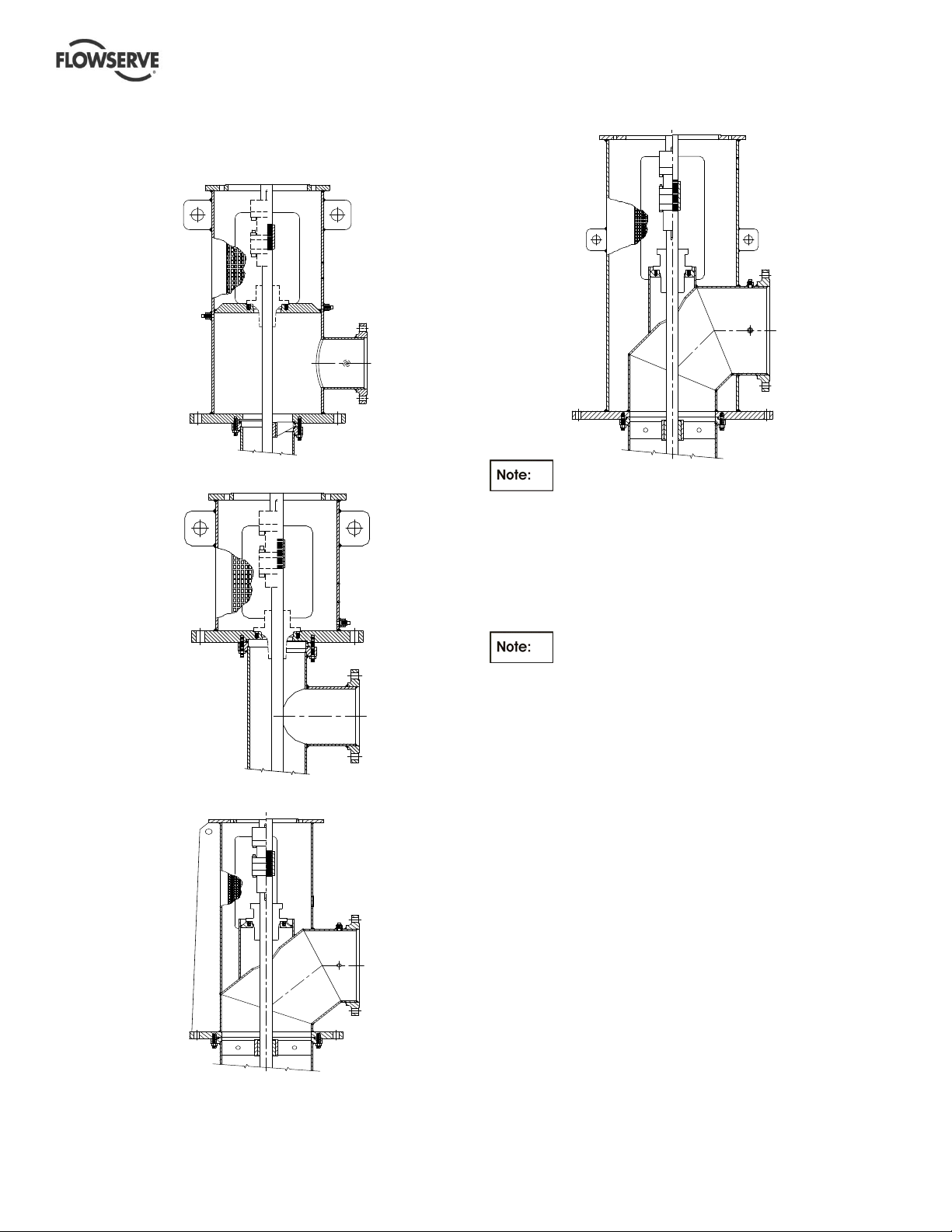
Column assembly
3.3.3
The column assembly consists of column pipe, which
connects the bowl assembly to the discharge head
and carries the pumped fluid to the discharge head.
Houses and supports the shaft and may contain
bearings. Typical column assemblies are:
a) flanged column assembly
See sectional drawings supplied with the pump for
exact column assembly details as per the order. The
size and configuration vary depending upon the
specific order requirements and application criteria.
3.3.4
Bowl assemblies
The bowl assembly consists of impellers rigidly
mounted on the pump shaft coupled to an electric
motor. Impellers are cast wheels with multiple diffuser
vanes and are generally coated to meet the hydraulic
requirements. See section 8.0 for cross sectional and
part details.
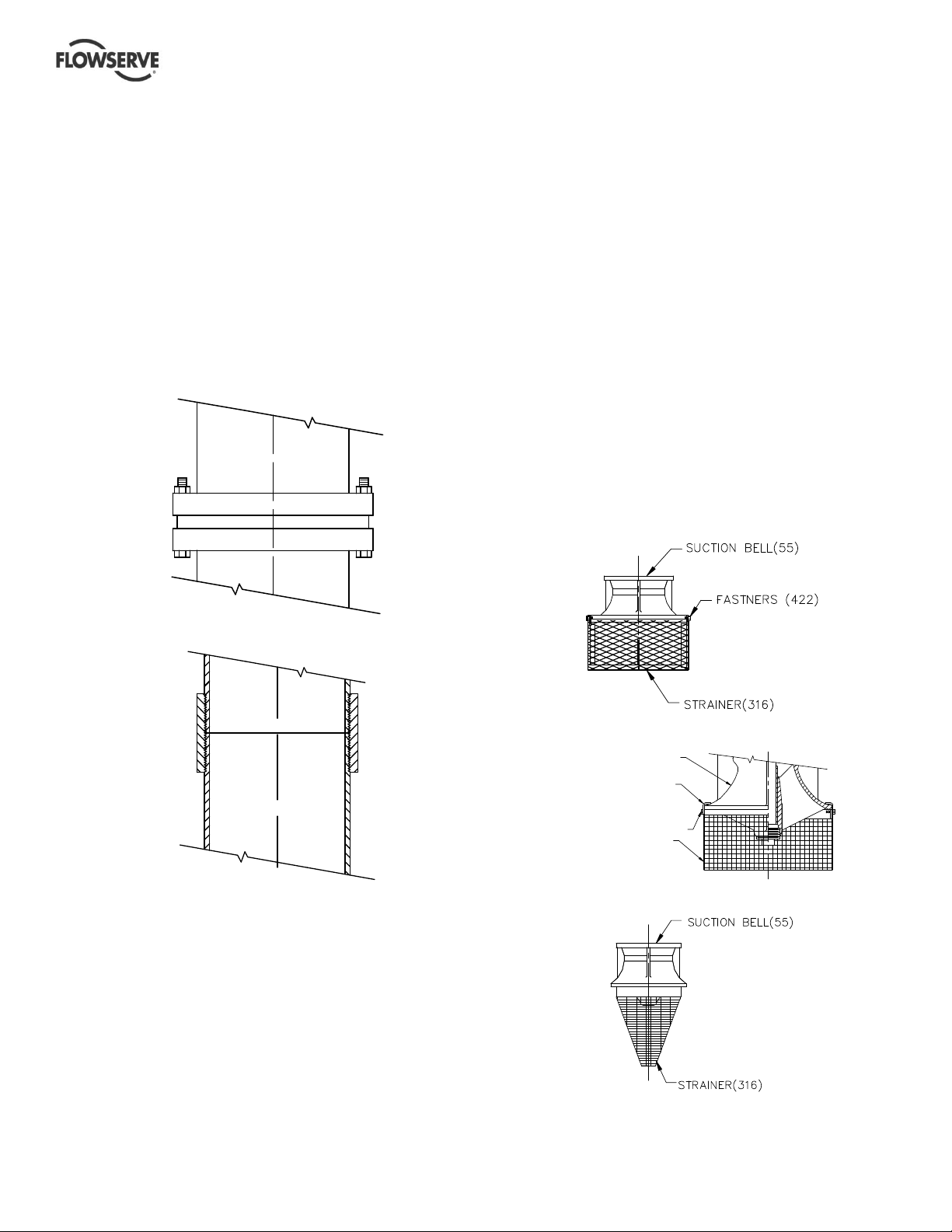
Suction strainers
3.3.5
VTPs can also be fitted with strainers [316] to prevent
foreign particles from entering the pump. The type of
strainers and the mesh size depends on the
application. Examples are shown below. Strainers
are fastened [422] directly to the suction bell [55] or
attached using clips [421]. Cone shaped strainers
are provided with internal or external threads to
attach it to the main assembly.
a) Slip-on strainer
b) threaded column assembly: from 100 mm~355
mm (4~14 in.) sizes only.
The column supports shaft assembly, that is either
a) Open lineshaft construction utilizing the fluid being
pumped to lubricate the lineshaft bearings.
Or
b) Enclosed lineshaft construction has an enclosing
tube around the lineshaft and utilizes oil or other
fluid to lubricate the lineshaft bearings.
The shafts are threaded or key coupled with thrust
stud design or clamp ring design.
b) Clip-on strainer
SUCTION BELL (55)
CLIP
(421)
CAP SCREW (422)
STRAINER (316)
c) Cone (threaded) strainer
Page 18 of 76 flowserve.com
Page 19
VERTICAL TURBINE PUMPS (VTPS) CENTRIFUGAL PUMPS ENGLISH 71569224 – 10-13
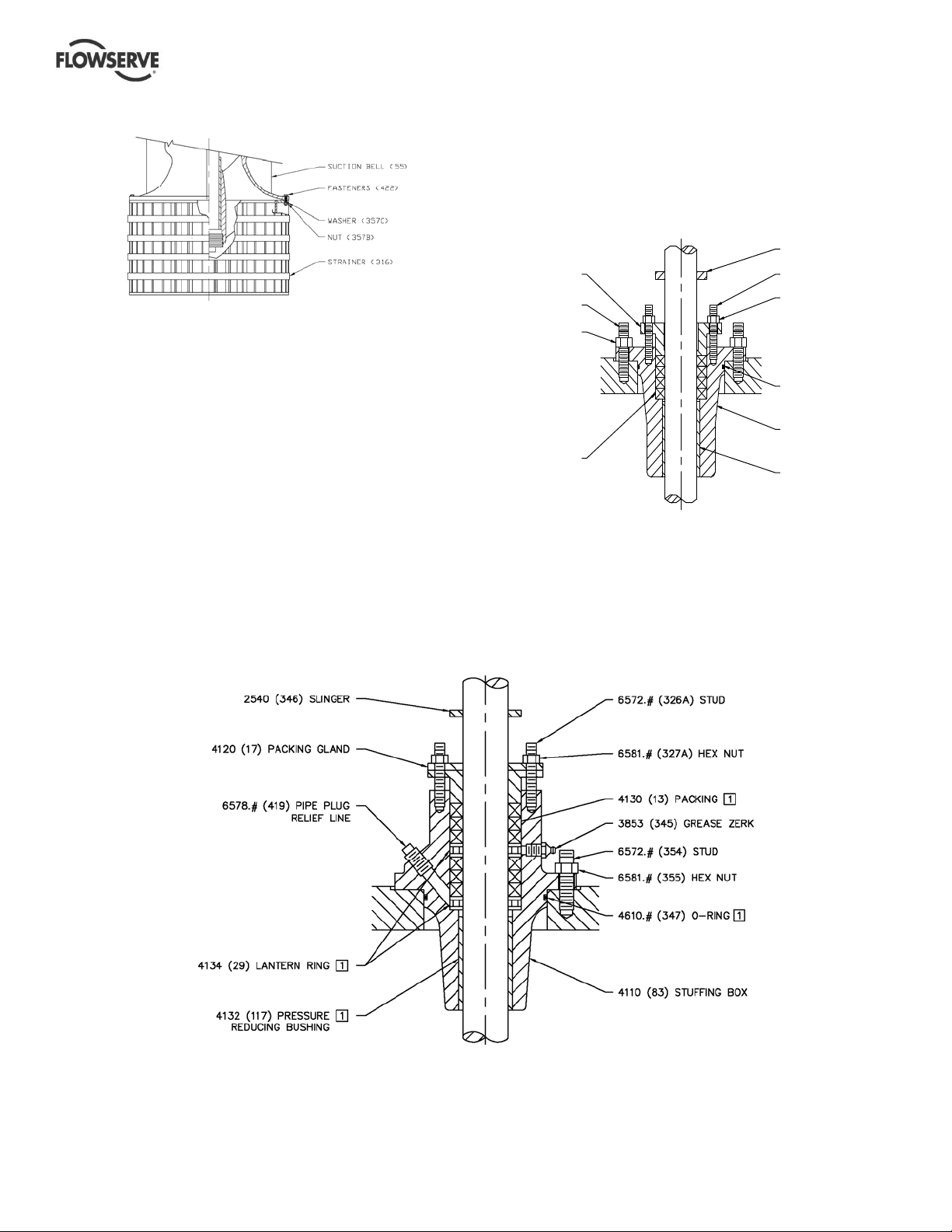
d) Bolt on strainer
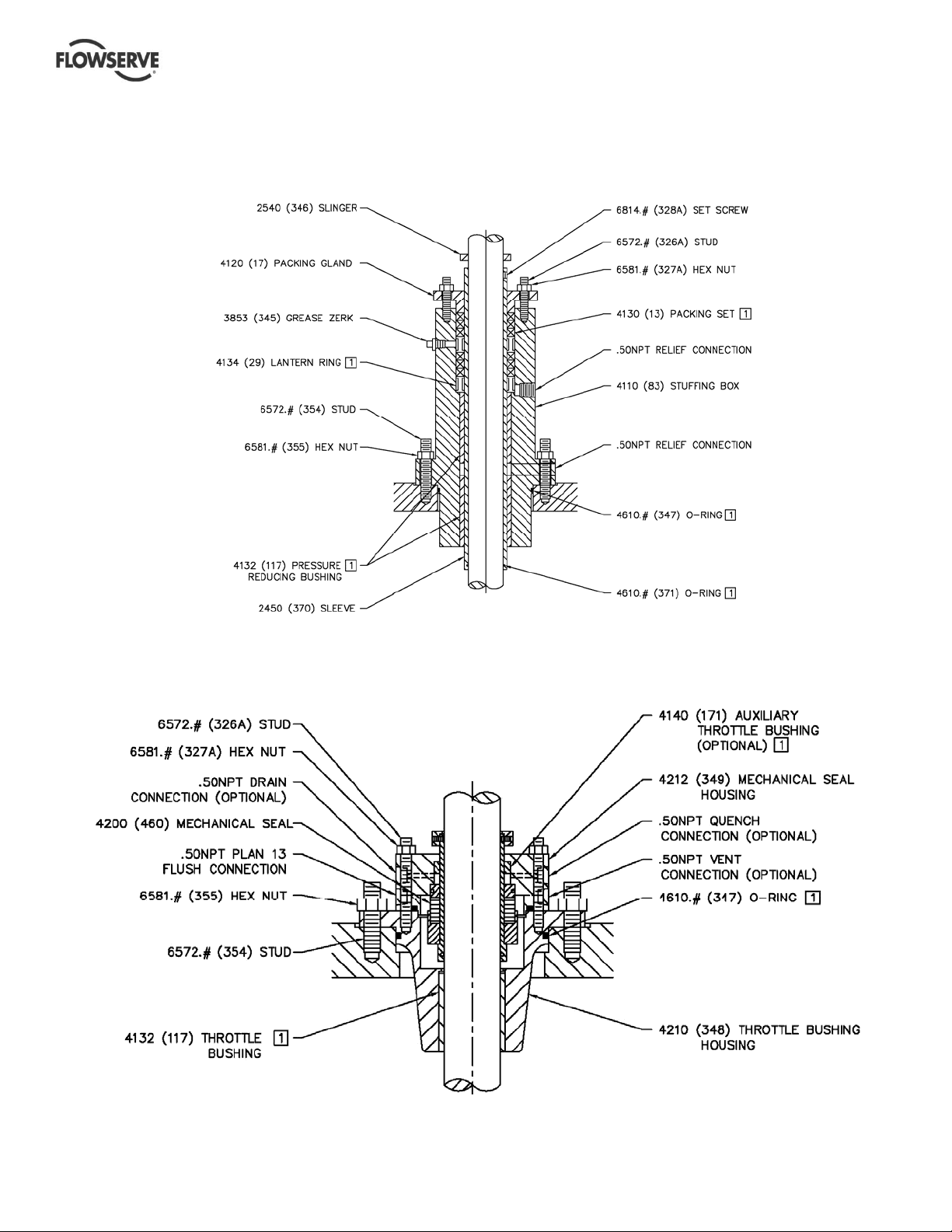
3.3.7.1
Low pressure stuffing box
This type of packing box is fitted on to an open
lineshaft for pressures less than 6.5 bar (100 psi) and
used only on W-type discharge heads (see Section
3.2.2.1 to see for W type discharge head detail).
SLINGER (346)
3.3.6
Impellers
(17) PACKING GLAND
(354) STUD
(355) HEX NUT
STUD (326A)
HEX NUT (32 7A)
VTP’s are supplied with enclosed, or semi open
impeller types. Impellers are low, medium and high
capacity type designed for maximum coverage of all
O-RING (347)
VTP applications. Impellers are cast and machined
to match each order and to provide required surface
finish to achieve hydraulic characteristics. Impellers
are dynamically balanced and held in position on the
shaft by a tapered lock collet or split ring and key.
Stuffing box
3.3.7
Some VTPs are fitted with stuffing boxes. In such
cases, stuffing boxes are normally adequate for
working pressures up to 20.7 bar (300 psi). Refer to
(13) PACKING SET
STUFFING BOX ( 83)
PRESSURE
REDUCING
BUSHING (117)
stuffing box User Instructions for specifications.
3.3.7.2
High pressure stuffing box
This type of packing box is fitted on to an open lineshaft for pressures up to 20 bar (300 psi) uses six rings of
packing with two lantern rings and allows grease lubrication.
Page 19 of 76 flowserve.com
Page 20
VERTICAL TURBINE PUMPS (VTPS) CENTRIFUGAL PUMPS ENGLISH 71569224 – 10-13
3.3.7.4
In cases where the pressures are expected to cross 20 bar (300 psi) up to 65 bar (1000 psi), extra highpressure stuffing box is used.
Extra high pressure stuffing box
3.3.8 Mechanical shaft seal
VTP’s can also be fitted with a mechanical seal. The requirement to fit the mechanical seal to be provided at
the time of contract.
Page 20 of 76 flowserve.com
Page 21
VERTICAL TURBINE PUMPS (VTPS) CENTRIFUGAL PUMPS ENGLISH 71569224 – 10-13
Accessories
3.3.8
Accessories may be fitted when specified by the
customer.
Performance and Operation Limits
3.4
This product has been selected to meet the
specifications of the purchase order. See section 1.5.
The following data is included as additional information to
help with the installation. It is typical and factors such as
temperature, materials and seal type may influence this
data. If required, a definitive statement for your particular
application can be obtained from Flowserve.
Operating limits
3.4.1
Pumped liquid temperature
limits*
Maximum ambient
temperature*
Maximum pump speed refer to the nameplate
*Subject to written agreement from Flowserve.
Special designs and materials may be available for
pumps operating above and below these specified
limits. Contact Flowserve for upgrade options
available for your specific application.
5 ºC (40 ºF) to +80 ºC (176 ºF)
Up to +40 ºC (104 ºF)
4 INSTALLATION
Equipment operated in hazardous locations
must comply with the relevant explosion protection
regulations. See section 1.6.4, Products used in
potentially explosive atmospheres.
Location
4.1
When equipment has been in storage for greater than 6
months, a complete inspection should be conducted in
accordance with section 2.4.3. The pump should be
located to allow room for access, ventilation,
maintenance and inspection with ample headroom for
lifting and should be as close as practicable to the
supply of liquid to be pumped. Refer to the general
arrangement drawing for the pump set.
Inspection prior to installation
4.1.1
Six months prior to the scheduled installation date, a
Flowserve Pump Division representative is to be
employed to conduct an inspection of the equipment
and the facility. If any deterioration of equipment is
noticed, the Flowserve Pump Division representative
may require a partial or complete dismantling of the
equipment including restoration and replacement of
some components.
Preparation
4.2
The pump should be located to allow room for access,
ventilation, maintenance and inspection with ample
headroom for lifting and should be as close as
practicable to the supply of liquid to be pumped.
Refer to the general arrangement drawing for the pump
dimensions and details.
General installation check-list
4.2.1
The following checks should be made before starting
actual installation.
a) Make sure that motor nameplate ratings and the
power supply system match correctly.
b) Check the sump depth and pump length match-
up.
c) Check the liquid level in the sump.
d) Check the installation equipment to be sure that it
will safely handle the pump weight and size.
e) Check all pump connections (bolts, nuts etc) for
any shipping and handling related problems.
Always support shafting in at least
three places when lifting or installing. No installation
should be attempted without adequate equipment
necessary for a successful installation.
On hollow shaft drivers, check the clutch size
On solid shaft drivers, check the motor shaft size
male shaft threads only at the time of making up
shaft connection. Excess lubricant should be
avoided.
connecting driver to pump. Reserve rotation due to
improper motor direction can cause extensive damage
to the pump.
4.3
pump units to their foundations. The correct method
depends on the size of the pump unit, its location and
vibration limitations. Non-compliance with the
against the shaft size, which must go through the
clutch
against the coupling bore size
Apply thread lubricant sparingly to
Always check motor rotation before
Foundation/Anchor Bolts
There are many methods of installing
Page 21 of 76 flowserve.com
Page 22
VERTICAL TURBINE PUMPS (VTPS) CENTRIFUGAL PUMPS ENGLISH 71569224 – 10-13
A
provision of correct foundation and installation may
lead to failure of the pump and, as such, would be
outside the terms of the warranty.
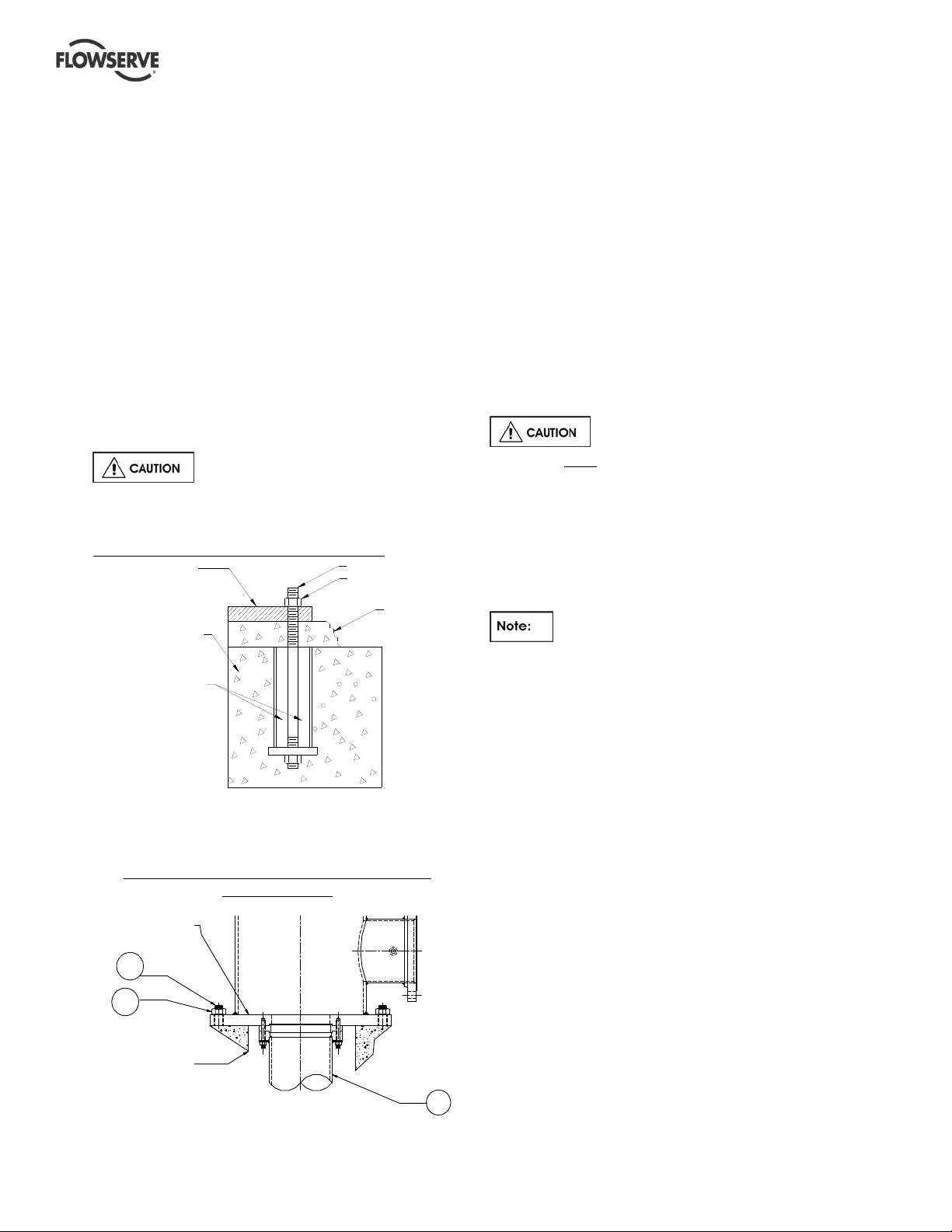
The foundation must consist of material that will afford
rigid support to the discharge head and will absorb
expected stresses that may be encountered in service.
Concrete foundations should have anchor bolts
installed in sleeves that allow alignment and have
holes in the mounting plate as illustrated in the detail
below. Sleeve should be filled with non-bonding
moldable material after sleeve is set in place.
When a suction barrel is supplied as in the case of the
type "TF" discharge head, the suction vessel must
provide permanent, rigid support for the pump and
motor.
All foundation / anchor bolt
recommendations should be verified by prevailing
industry standards.
Detail of a typical foundation bolt, grouted.
MOUNTING PLATE
FOUNDATION
NON-BONDING
MOLDABLE MATERIAL
NCHOR BOLT
NUT
GROUT
4.3.1
Leveling of pumps mounted on the
discharge head flange
Example of a typical discharge head with the
mounting flange
DISCHARGE
HEAD FLANGE
372
373
CONCRETE
Some wet pit pumps are installed directly by using
the flange that comes as an integral part of the
discharge head. The pump is lowered into the pit
and aligned with the anchor bolts [372].
The mounting flange is shimmed to achieve required
level by using a precision machinist’s level. The
pump is to be leveled to within 0.16 mm/m
(0.002 in./ft). The data to be recorded for future
reference. Anchor bolt nuts [373] are tightened
sufficient enough to hold down the pump in place.
Grout is poured and allowed to set for at least 72~80
hours (cure as required) before any further work is
done on the pump.
If leveling nuts are used to level the
base, they must be backed off as far as possible prior
to grouting.
Always shim near foundation bolts and then back off
the leveling nuts. Now tighten the foundation bolts. If
done otherwise there is a risk of significantly lowering
the structural natural frequency that could result in
separation of the base from the grout.
Directly mounted pumps are not user
friendly for service. Re-installation of these pumps
requires re-leveling and re-grouting.
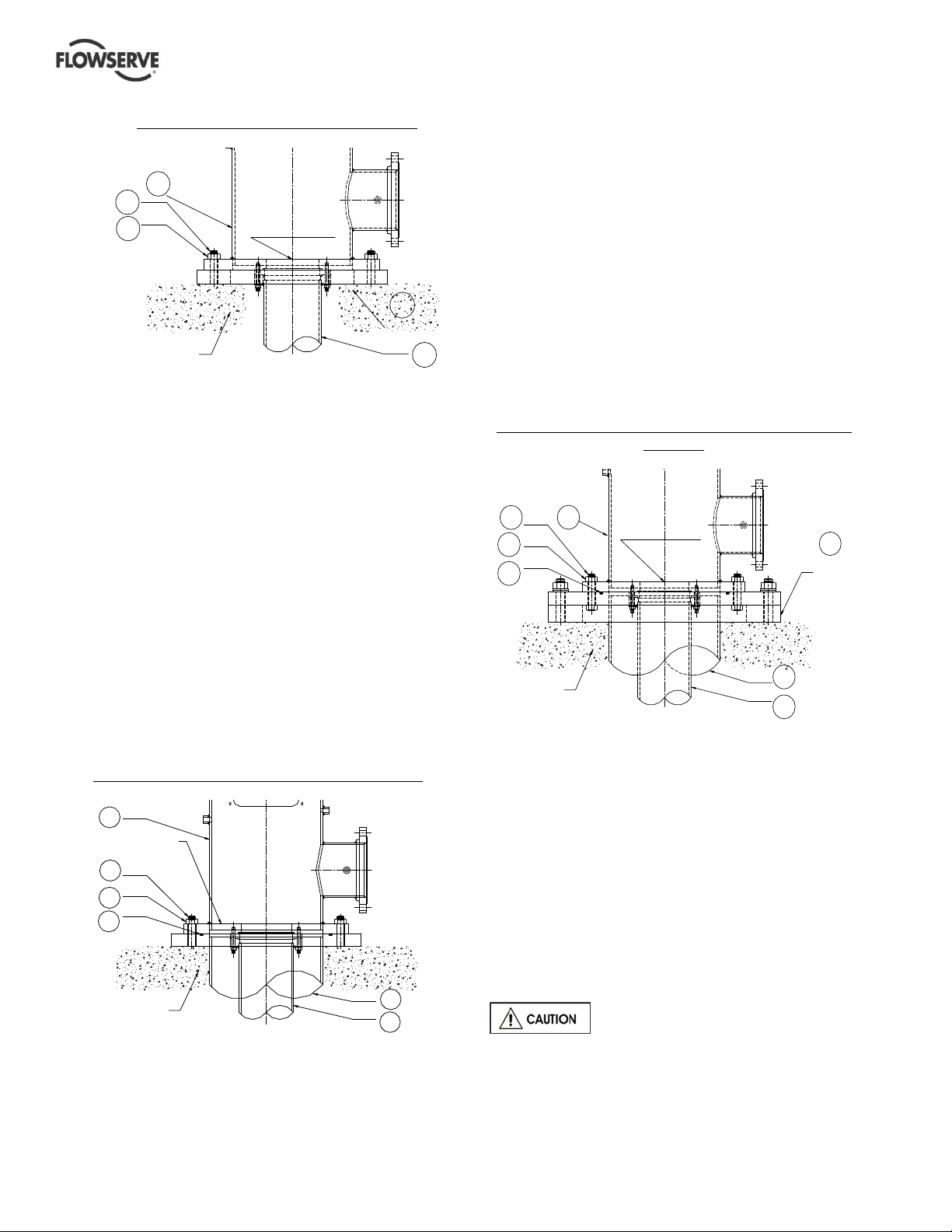
Leveling of pumps mounted on a
4.3.2
soleplate and the soleplate is grouted
Some pumps are mounted on a separate plate
known as soleplate [23]. In such cases, the level
shall be set with a master level or a precision
machinist’s level. The mounting surface needs to be
leveled to within 0.16 mm/m (0.002 in./ft).
The level should not exceed 0.125 mm (0.005 in.)
elevation difference taken on any two points on the
individual soleplate. Accurate shimming and grouting
of the soleplate is very important. Record the leveling
data for future reference. Grout the soleplate and
allow to set at least 72~80 hours (cure as required)
before the pump is lowered into the pit. Align the
discharge head boltholes with the anchor bolts [372].
Check and adjust the pump level to within
0.16 mm/m (0.002 in./ft) with respect to the soleplate
and torque the nuts [373] to the required level.
101
Page 22 of 76 flowserve.com
Page 23
VERTICAL TURBINE PUMPS (VTPS) CENTRIFUGAL PUMPS ENGLISH 71569224 – 10-13
Example of pump mounted on a soleplate
304
372
373
CONCRETE
FOUNDATION
DISCHARGE
HEAD FLANGE
23
SOLE
PLATE
101
4.3.3
Leveling of pumps with the suction barrel
(also referred as “Can” VTPs)
The suction barrel [315] is first lowered into the pit and
aligned with the anchor bolts [372]. The suction barrel
flange is leveled by using a master level or a precision
machinist’s level. Levels should be taken on the
equipment mounting surfaces. The suction barrel
flange mounting surface needs to be leveled to within
0.16 mm/m (0.002 in./ft) using shims and grouted.
Allow the grout to set for at least 72~80 hours before
the pump is installed. Check the barrel mounting
surface level after the grout is set and then proceed
with the pump installation. Lower the pump assembly
into the pit and align the discharge head flange bolt
holes to the anchor bolts [372].
Check and adjust the pump level with respect to the
barrel flange to within 0.16 mm/m (0.002 in./ft) and
final torque the nuts [373]. The leveling data to be
recorded for future reference.
Example of a pump installed with a suction barrel.
304
DISCHARGE
HEAD FLANGE
372
373
374
CONCRETE
FOUNDATION
315
101
Leveling of pumps with suction barrel
4.3.4
mounted on a soleplate
The soleplate [23] is installed on the foundation and
aligned with the anchor bolts [372]. Level the
soleplate with the help of a machinist’s level to within
0.16 mm/m (0.002 in./ft). Tighten the nuts [373] and
grout. Cure and allow grout to set for 72~80 hours.
Lower the suction barrel into the pit and level again
with respect to the soleplate [23] to within 0.16 mm/m
(0.002 in./ft). The level should not exceed 0.125 mm
(0.005 in.) elevation difference taken on any two
points on the soleplate. The pump [101] is now
lowered into the suction barrel and installed. Make
sure that the discharge head flange is still in level
within 0.16 mm/m (0.002 in./ft) with respect to the
suction barrel [315].
Example of pump with a suction barrel mounted on a
soleplate
372
373
374
CONCRETE
FOUNDATION
4.4
304
Grouting
DISCHARGE
HEAD FLANGE
23
SOLE
PLATE
315
101
Where applicable, grout in the foundation bolts.
After adding pipe work connections and re-checking
the coupling alignment, the mounting plate/soleplate
should then be grouted in accordance with good
engineering practice. If in any doubt, please contact
Flowserve service center for advice.
Grouting provides solid contact between the pump
unit and foundation that prevents lateral movement of
running equipment and dampens resonant vibrations.
Care should be taken to ensure maximum surface
contact with grout between the pump base, sole
plate, suction can and foundation (no voids).
Foundation bolts should only be fully
tightened after the grout has been cured.
Page 23 of 76 flowserve.com
Page 24

VERTICAL TURBINE PUMPS (VTPS) CENTRIFUGAL PUMPS ENGLISH 71569224 – 10-13
Lifting and Assembly
4.5
Motors may be supplied separately from the pumps.
It is the responsibility of the installer to ensure that
the motor is assembled to the pump and aligned as
detailed in section 4.5. Discharge head column
piping and the pump assembly are supplied either
separately or as fully assembled depending upon the
pump size and weight. If the parts are shipped
separately, it is the customer’s responsibility to install
and align the pump with driver to the satisfaction of
Flowserve’s installation instructions.
Installation of pumps that are shipped
4.5.1
unassembled
4.5.1.1
See lifting methods in section 2.3.
4.5.1.2
The following list covers the principal tools/items
required for installation.
a) Two (2) mobile cranes capable of hoisting and
b) Two (2) steel clamps of suitable size.
c) Two (2) sets of chain tongs & cable sling for
d) Pipe clamp for lifting bowl assembly and the
e) General purpose hand tools, pipe wrenches, end
f) Thread sealing compound designed for stainless
inside shipping containers or attached to skids in
individual packages. Inspect all containers, crates
and skids for attached parts before discarding.
4.5.1.3
a) Clean the parts of any dirt, packing material and
b) Flush the pump inside and outside with clean
c) Remove any rust spots found on the machined
d) Clean all threaded connections and any accessory
Lifting
Equipment and tools required for
installation of unassembled pumps
lowering the pump and/or motor.
attaching to the pump and motor lifting eyes.
column pipe. Approximately 4.5 m (15 ft) of 19
mm (3/4 in.) diameter rope may be required.
wrenches, socket set, screwdrivers, Allen
wrenches, wire brush, scraper and fine emery
cloth.
steel and light machinery oil.
Parts and accessories may be placed
Uncrating and cleaning of unassembled
pump
other foreign matter.
water. Clean all machined surfaces.
surfaces with fine emery cloth.
equipment.
Lineshaft when shipped separately
should be left in the crate to avoid damage or loss of
straightness.
4.5.1.4
a) Sump and piping should be thoroughly cleaned
b) Check all bolts for tightness.
c) Do not lift or handle the bowl assembly by the
d) When installing bowl assemblies in sizes of 152
e) If a strainer is to be used, attach it to the bowl
f) Position lifting equipment so it will center over the
g) If a base plate is used, level the plate to 0.16 mm
h) Check for axial clearance or endplay and record
i) Carefully lift the suction barrel and the bowl
j) Lower the bowl assembly into the well or sump.
k) Proceed to install the column assembly (refer to
4.5.1.5
Choose one of the following discharge head type
installation procedure that is appropriate to the pump
configuration that has been purchased
4.5.1.5.1
housing installed. For ease of assembly and to
prevent damage, we recommend removing the
housing before putting the head on the pump.
Installing the bowl and column
assembly
of all loose debris before starting installation.
pump shaft.
mm (6 in.) or 203 mm (8 in.), leave bowl securely
fastened to the wooden skid that is attached for
shipping until the bowl assembly is raised to a
vertical position. This will help prevent breaking
the bowls or bending the shaft.
assembly using fasteners as necessary..
foundation opening.
per m (0.002 in. per ft) and then grout and anchor
in place.
that number for future reference (while bowls are
in a horizontal position you should be able to push
or pull the pump shaft indicating axial clearance).
assembly with suitable straps or clamps (See
section 2.4 for lifting and safety rules).
Set clamp or holding device that is attached to
bowls on a flat surface. This is to stabilize bowl
assembly and reduce possibility of cross threading
the shaft.
specific column pipe drawings).
Installation of discharge head
Installation of discharge head with product
lubrication
Pump head may be shipped with the sealing
Page 24 of 76 flowserve.com
Page 25

VERTICAL TURBINE PUMPS (VTPS) CENTRIFUGAL PUMPS ENGLISH 71569224 – 10-13
For pumps supplied with hollow shaft drivers and a
one-piece headshaft (headshaft couples below
sealing housing) proceed to step (a).
For pumps supplied with a two-piece headshaft
(headshaft couples above the sealing housing) or
solid shaft drivers, proceed to step (b) directly
skipping step (a).
a) Attach the headshaft to the lineshaft with a
coupling and tighten (left hand threads).
b) Lift discharge head over shaft and lower carefully
into place (See section 2.3 for recommended
lifting methods and safety instructions). Be sure
not to bend the shaft. Fasten the top column
flange and bearing retainer, if supplied to bottom
of head. (Note that W heads do not have a
bearing retainer at the top column flange).
c) If baseplate is not included use shims or wedges
between the pump and foundation to level the
pump. The shaft must be centered in the
discharge head.
See section 4.4.4 for coupling installation on solid
shaft drivers and section 4.2.1~4.2.4 for pump
leveling details
4.5.1.5.2
Installation of discharge head with the
enclosing tube
Pump head may be shipped with the sealing
housing installed. For ease of assembly and to
prevent damage, we recommend removing the
housing before putting the head on the pump.
For pumps supplied with hollow shaft drivers and a
one-piece headshaft (headshaft couples below
sealing housing) proceed to step (a). For pumps
supplied with a two-piece headshaft (headshaft
couples above the sealing housing) or solid shaft
drivers, proceed to step (b) directly skipping step (a).
a) Attach the headshaft to the lineshaft with a
coupling and tighten (left hand threads).
b) Attach the top enclosing tube to the column
enclosing tube and tighten (left hand threads).
c) Lift the discharge head over shaft and enclosing
tube then lower carefully into place ( See section
2.3 for recommended lifting methods and safety
instructions). Be sure, not to bend the shaft.
Fasten the top column flange and alignment ring if
supplied to bottom of head. (W heads do not have
an alignment ring at the top column flange).
d) Use shims or wedges between the pump and
foundation to level the pump. The shaft must be
centered in the discharge head.
See section 4.4.4 for coupling installation on solid
shaft drivers and section 4.2.1~4.2.4 for pump
leveling details.
Installation of pumps that are shipped
4.5.2
fully assembled
4.5.2.1
Lifting
See lifting methods in section 2.3.
4.5.2.2
Equipment and tools required for
installation of a fully assembled pump
a) Mobile crane capable of hoisting and lowering the
entire weight of the pump and motor.
b)
Cable slings for attaching to the pump and motor
lifting eyes.
c)
Ordinary hand tools: Pipe wrenches, end
wrenches, socket set, screwdrivers, Allen
wrenches, wire brush, scraper and fine emery
cloth.
d)
Thread sealing compound designed for type of
connection and light machinery oil.
The single most common cause of pump
vibration is from a bent shaft. Shafting is
straightened to stringent tolerances prior to shipping
and great care must be exercised in its handling.
Always support shafting in at least three places when
lifting or installing.
Parts and accessories may be placed
inside shipping containers, or attached to skids in
individual packages.
Inspect all containers, crates and skids for attached
parts before discarding.
Lifting heavy objects is dangerous. Use of
appropriate tools and procedures is must.
4.5.2.3
Uncrating and cleaning of a fully
assembled pump
a) Clean the parts of all dirt, packing material and
other foreign matter.
b) Flush the pump inside and outside with clean
water.
c) Clean all machined surfaces. Remove any rust
spots found on the machined surfaces with fine
emery cloth.
d) Clean all threaded connections and any accessory
equipment.
Page 25 of 76 flowserve.com
Page 26

VERTICAL TURBINE PUMPS (VTPS) CENTRIFUGAL PUMPS ENGLISH 71569224 – 10-13
4.5.2.4
Installing the fully assembled pump
If a base plate is used, level the plate to 0.16 mm per
m (0.002 in. per ft), grout and anchor in place.
See sections 4.2.1~4.2.4 for pump leveling details.
Position lifting equipment so it will center over the
foundation opening.
Installation of couplings on solid shaft
4.5.3
drivers.
If the pump purchased is having a solid
shaft driver, one of the following coupling
arrangement between the driver and the pump shaft
is applicable. Choose the procedure appropriate to
the coupling arrangement required.
Sump and piping should be
thoroughly cleaned of all loose debris before starting
installation.
Set up installation unit so that the lifting cable will be
centered directly over the well or sump. Carefully lift
the bowl assembly and suction barrel with a clamp.
Lower the bowl assembly into the well or sump. Set
the clamps or holding device that is attached to bowls
on a flat surface. This is to stabilize bowl assembly
and reduce possibility of cross threading the shaft.
a) When installing 152 mm (6 in.) or 203 mm (8 in.)
pump assembly, leave the pump securely
fastened to the wooden skid (as shipped) until the
bowl assembly is raised to a vertical position
b) Lift the pump to a vertical position. If a strainer is
used, attach it to the bowl assembly.
c) Position pump over sump or suction barrel. Align
the discharge of the pump with external piping
then lower onto the base. Level the entire pump.
d) If a stuffing box and a hollow shaft driver are
included, attach the head shaft to the pump shaft
(left hand threads).
e) If a mechanical seal is included, install the seal at
this point per the attached instructions.
If the pump includes a suction barrel (can), follow the
procedure as listed below. (See lifting instructions in
section 2.3)
a) Install the suction barrel first and grout the
mounting flange and bolts directly to the
foundation.
b) If soleplate is used, mount and grout the
soleplate and mount the suction barrel onto the
soleplate.
c) Level the soleplate & the suction barrel flange as
required.
d) Check to ensure suction barrel is free of debris
and other foreign material.
e) Install the pump.
Clean threads on pump shaft and on
adjusting nut.
Check for burrs and nicks.
All burrs, nicks and rust must be removed from all
mating parts of flanged coupling and pump before
installation. Failure to remove all burrs, nicks and
rust may result in misalignment causing pump to fail.
4.5.3.1
Installation of adjustable flanged
coupling WA/PA.
a) The key [46A] for the driver shaft keyseat should
be a snug or tight fit in the shaft keyseat, and a
sliding fit in the keyseat of the driver half coupling
[42].
b) The key with pin [46] should be a sliding fit in
pump shaft keyseat and a snug or tight fit in pump
half coupling [44] keyseat.
c) Side clearance of keys in keyseats should be
checked with a feeler gauge. Clearance for
WA/PA coupling should not exceed 0.076 mm
(0.003 in.) for a snug fit or 0.127mm (0.005 in) for
a sliding fit. These are maximum allowable
clearances. Closer fits are preferred, if possible.
It may be necessary to file-dress keys to obtain
proper fit.
d) Insert the key [46] with pin into pump half of
coupling [44] putting the pin in the hole in keyseat.
The key should not extend below coupling.
e) Lubricate pump coupling half and key assembly
with light oil and slide it onto pump shaft [12A] with
flange up. Slide it past threads.
f) Lubricate adjusting nut [66A] with light oil and
thread it onto pump shaft [12A] (left hand threads)
with male register down. Thread it on until top of
shaft and top of nut are even.
g) Uncrate and lift driver to allow access to drive
shaft.
The driver must be set on supports
capable of carrying the entire weight of the driver
before proceeding to step (h). Failure of supports
could cause damage to the motor or loss of life.
h) Clean and check driver shaft. Remove any burrs.
Page 26 of 76 flowserve.com
Page 27

VERTICAL TURBINE PUMPS (VTPS) CENTRIFUGAL PUMPS ENGLISH 71569224 – 10-13
i) Check the fit of the straight key and split thrust
rings [312A] in their respective keyseats. (Refer to
paragraph (a) regarding fit of the straight key).
j) Install straight key into keyseat. The bottom of the
key must be above the top of circular keyseat for
the split thrust rings.
k) Lubricate driver half coupling lightly and slide it
onto driver shaft. Slide bottom of coupling above
the top of the keyseat for split thrust rings.
l) Install split thrust rings into circular keyseat and
slide the coupling down over them.
m) Tighten the coupling bolts as follows.
Coupling bolts tightening torques
Coupling
size
1 & 2
3, 4 & 5
6
Torque values are for standard fasteners lubricated with a high
stress lubricant (such as, graphite and oil, moly-disulphite, white lead
etc.). For stainless steel bolts, multiply listed torques by 0.80.
Flange diameter
mm (in.)
112 & 137
(4.4 & 5.4)
156, 188, & 213
(6.1, 7.4, & 8.4)
251
(9.9)
Torque N·M
(In·lb)
121.5 (1075)
237.0 (2100)
424.0 (3750)
n) Proceed with the driver installation.
MOTOR SHAFT
4.5.3.2
Installation of adjustable flanged spacer
coupling WSA/PSA.
Follow procedure from (a) thru (l) as listed in section
4.5.4.1.
c) Bolt spacer [314] to the driver half coupling [42]
using the short set of socket head cap screws
[364]. The male register should be pointing
down. Tighten all cap screws evenly to the bolt
torques as listed in 4.5.4.1 under item (m).
d) Proceed with the driver installation.
MOTOR SHAFT
(42) DRIVER COUPLING
HALF
(46A) DRIVE KEY
(312A) SPLIT THRUST
RING
(314) SPACER
(364) CAP SCREW
(42) DRIVER COUPLING
HALF
(46A) DRIVE KEY
(312A) SPLIT THRUST
RING
(66A) ADJUSTING NUT
(44) DRIVEN COUPLING
HALF
(363) HEX NUT
(44) DRIVEN COUPLING
HALF
(364) CAP SCREW
(46) KEY ASSEMBLY
(364) CAP SCREW
(46) KEY ASSEMBLY
(12A) TOP SHAFT
(12A) TOP SHAFT
TYPE- WSA/PSA COUPLING DEATILS
TYPE WA/PA COUPLING DETAIL
Page 27 of 76 flowserve.com
Page 28

VERTICAL TURBINE PUMPS (VTPS) CENTRIFUGAL PUMPS ENGLISH 71569224 – 10-13
4.5.3.3
Installation of non-adjustable flanged
coupling WNA/PNA.
Follow procedure from (a) thru (e) as listed in section
4.5.4.1.
f) Install one set of split thrust rings [312A] in to the
circular keyway in pump shaft. Pull up the pump
half of the coupling [44] over the split keys.
g) Slide driver half coupling [42] onto driver shaft in
the same manner as the pump half of the
coupling.
h) Set the spacer ring [314] between the two halves
of the coupling together. Tighten all cap screws
[364] evenly to the bolt torques as listed in
4.5.4.1 under item (m).
i) Proceed with the driver installation.
MOTOR SHAFT
(42) DRIVER COUPLING
HALF
(363) HEX NUT
(46A) DRIVE KEY
(312A) SPLIT THRUST
RING
(314) SPACER RING
(312A) SPLIT THRUST
RING
(44) DRIVEN COUPLING
HALF
(364) CAP SCREW
(46) KEY ASSEMBLY
(12A) TOP SHAFT
TYPE-WNA/PNA COUPLING DETAILS
4.5.4
Installation of drivers
Drivers will come with either hollow shaft or
solid shaft as specified on the order/contract.
Choose the correct installation procedure from the
following paragraphs.
Reverse rotation with the pump shaft
connected can cause extensive damage to the pump.
Always check rotation before connecting driver to
pump.
4.5.4.1
Installation of hollow shaft driver
a) Clean driver mounting flange on discharge head
and check for burrs or nicks on the register and
mounting face. Oil lightly.
b) Remove driver clutch.
c) See (j) regarding installation of motor guide
bushing, if required.
d) Lift driver and clean mounting flange, checking for
burrs and nicks.
e) Center motor over pump and rotate to align
mounting holes.
Electric motors - rotate junction box into desired
position.
Gear Drives - rotate input shaft into desired
position.
f) Lower carefully into place making certain that the
female register on the driver mates over the male
register on the pump.
g) Bolt driver to discharge head.
h) Check the driver manufacturer's instruction
manual for special instructions including
lubrication instructions and follow all "startup"
directions.
i) Electric motors should be checked for rotation at
this time. Make certain the driver clutch has been
removed. Make electrical connections and
"bump" motor (momentarily start, then stop) to
check rotation. DRIVER MUST ROTATE
COUNTERCLOCK-WISE when looking down at
top end of motor. To change the direction of
rotation on a three-phase motor, interchange any
two line leads. To change direction of rotation on
a two phase motor, interchange the leads of either
phase
j) Some motors will be supplied with a "lower guide
bushing" or "steady bushing" which is installed at
the bottom of the motor to stabilize the shaft at this
point. Some motor manufacturers mount this
guide bushing before shipping while others will
ship the guide bushing with instructions for field
mounting.
Page 28 of 76 flowserve.com
Page 29

VERTICAL TURBINE PUMPS (VTPS) CENTRIFUGAL PUMPS ENGLISH 71569224 – 10-13
k) Check the packing slip to see if a guide bushing is
required, if so, determine if the bushing is already
mounted or not and proceed accordingly. Refer to
motor instruction manual.
l) Carefully install drive clutch on driver making sure
that it fits down properly.
m) Clean threads on top of head shaft and head shaft
nut. Lubricate male threads lightly. Install head
shaft.
n) Install gib key [335] in clutch and shaft. This must
be a sliding fit and may require filing and dressing.
Do not force.
o) Thread adjusting nut down on shaft until it bears
against clutch. (Threads on 43 mm (1.68 in.) and
larger head shaft adjusting nuts are left-handed
and all others are right handed). Do not thread
nut further at this time. See impeller adjusting
instructions in section 5.3.
(334) LOCK SCREW
COUPLING
HEAD SHAFT (10)
HEAD SHAFT NUT (66)
DRIVER
GIB KEY(335)
4.5.4.2
Installation of solid shaft driver without
jacking screws
When lowering the motor and driver
half of coupling onto pump, do not let pump half of
the coupling touch the driver half of the coupling.
Before bumping motor make sure coupling halves
are not touching and that the driver can rotate freely,
without rotating the pump
Driver half coupling must be in proper position so the
circular key will not come out.
a) Clean driver mounting flange on discharge head
and check for burrs or nicks on the register and
mounting face. Oil lightly.
b) Center motor over pump and rotate to align
mounting holes.
Electric motors: Rotate junction box into desired
position.
Gear Drives: Rotate input shaft into desired
position.
c) Lower driver carefully into place making certain
that the female register on the driver mates over
the male register on the pump.
d) Bolt driver to discharge head.
e) Check driver manufacturer's instructions for
special instructions including lubrication
instructions and follow all "startup" instructions.
f) Electric drivers should be checked for rotation at
this time. Make electrical connections "bump"
motor (momentarily start, then stop) to check
rotation. DRIVER MUST ROTATE
COUNTERCLOCKWISE when looking down at
top end of motor. To change the direction of
rotation on a three-phase motor, interchange any
two line leads. To change direction of rotation on
a two-phase motor, interchange the leads of either
phase.
g) See impeller adjustment instructions (section 5.3)
before bolting the pump and driver half of the
coupling together.
4.5.4.3
Installation of solid shaft driver with
jacking screws
a) Clean driver mounting flange on discharge head
and check for burrs or nicks on the register and
mounting face. Oil lightly.
b) Center motor over pump and rotate to align
mounting holes.
Electric motors: Rotate junction box into
desired position.
Gear Drives: Rotate input shaft into desired
position.
c) Lower driver carefully into place. Mount the dial
indicator base on the O.D. of the motor half
coupling. Set the indicator on the pump shaft,
position the dial to zero being careful that the
indicator is in direct line with one of the
jackscrews. Record this reading then rotate the
motor shaft and indicator 180 degrees. Record
this reading being careful to note plus or minus
values. Take the difference of the two readings
and using the jackscrews move the motor onehalf of the difference. Repeat this step until the
T.I.R. reading is a maximum of 0.051mm
(0.002in.). Then repeat this step for the set of
jack screws located 90 degrees to the first set.
Once all readings are within 0.051mm (0.002in.),
tighten motor bolts and check for any movement
in readings.
d) Check driver manufacturer's instructions for
special instructions including lubrication
instructions and follow all "startup" instructions.
e) Electric drivers should be checked for rotation at
this time. Make electrical connections and
"bump" motor (momentarily start, then stop) to
check rotation. DRIVER MUST ROTATE
COUNTER-CLOCKWISE when looking down at
top end of motor. To change the direction of
rotation on a three-phase motor, interchange any
Page 29 of 76 flowserve.com
Page 30

VERTICAL TURBINE PUMPS (VTPS) CENTRIFUGAL PUMPS ENGLISH 71569224 – 10-13
two line leads. To change direction of rotation on
a two-phase motor, interchange the leads of
either phase.
f) See impeller adjustment instructions (section 5.3
before bolting the pump and driver half of the
coupling together.
Initial Alignment
4.6
4.6.1
Thermal expansion
The pump and motor will normally
have to be aligned at ambient temperature and
should be corrected to allow for thermal expansion at
operating temperature. In pump installations
involving high liquid temperatures greater than 300°F,
the unit should be run at the actual operating
temperature, shut down and the alignment checked
immediately.
Preparation before alignment
4.6.2
To ensure proper alignment the following items are
very important.
a) All machined mating surfaces (such as the
mating flanges of pump and motor) must be
clean and free of burrs and nicks.
b) Exterior strain must not be transmitted to the
pump. The most common cause of trouble is
forcing the piping to mate with the pump. It is
recommended that flexible connectors be installed
in the piping adjacent to the pump.
c) All threads should be checked for damage and
repaired if necessary. Lubricate all threaded
connections with a suitable thread lubricant (an
anti-galling compound).
Alignment methods
4.6.3
Ensure pump and driver are isolated
electrically and the half couplings are disconnected.
The alignment MUST be checked.
Although the pump will have been aligned at the
factory it is most likely that this alignment will have
been disturbed during transportation or handling.
If necessary, align the motor to the pump, not the
pump to the motor.
Adding or removing shims between the
motor and the discharge head helps alignment in the
vertical direction. The motor assembly may also
have to be adjusted in the horizontal direction to line
up the driver and shaft centers. Alignment screws
are provided to lock the motor assembly in its final
aligned position.
See section 5.3.2.1 for final coupling alignment for
solid shaft.
Before bumping motor make sure that the
coupling halves are not touching and that the driver
can rotate freely without rotating the pump. Driver
half coupling must be in proper position so the
circular key will not come out.
Angular and parallel misalignment
4.6.4
Check the direction of pump rotation
before the coupling is fully connected. The power
supply to the driver to be connected only after the
final alignment is complete.
a)
Angular of fset
Axial offset
b)
c)
Parallel offset
a) Angular Offset: The median lines of shaft
intersect halfway between the ends of the two
shafts.
b) Axial Offset: Another offset is the displacement
of one or both of the shafts. A typical example is
thermal expansion.
c) Parallel Offset: The median lines run parallel.
The maximum allowable parallel offset depends
on the size of coupling and is indicated in the
instruction manual of manufacturer of coupling.
For couplings with narrow flanges use a dial indicator
as shown in the detail to check both parallel and
angular alignment.
Page 30 of 76 flowserve.com
Page 31

VERTICAL TURBINE PUMPS (VTPS) CENTRIFUGAL PUMPS ENGLISH 71569224 – 10-13
A
Par al l el
ngular
a) Pumps with thick flanged non-spacer couplings
can be aligned by using a straight-edge across
the outside diameters of the coupling hubs and
measuring the gap between the machined faces
using feeler gauges, measuring wedge or
calipers.
b) When the electric motor has sleeve bearings, it is
necessary to ensure that the motor is aligned to
run on its magnetic centerline.
Refer to the motor User Instructions for details.
If the motor does not run in its
magnetic center the resultant additional axial force
may overload the pump thrust bearing.
If the pump is handling hot liquid, the alignment must
be rechecked in warm condition of the unit. The
alignment of the unit shall be checked again after 200
service hours.
Pipe work velocities
4.7.1
In order to minimize friction losses and hydraulic
noise in the pipe work it is good practice to choose
pipe work that is one or two sizes larger than the
pump suction and discharge.
Typically, main pipe velocities should not exceed 2
m/s (6 ft/sec) on the suction and 3 m/s (9 ft/sec) on
discharge.
Take into account the available NPSH that must be
higher than the required NPSH of the pump.
Never use the pump as a support for
piping.
Maximum forces and moments allowed on
4.7.2
VTP pump flanges (See table 4.6.2.1)
Maximum forces and moments allowed on the pump
flanges vary with the pump size and type. To
minimize these forces and moments that may, if
excessive, cause misalignment, hot bearings, worn
couplings, vibration and possible failure of the pump
casing. The following points should be strictly
followed.
a) Prevent excessive external pipe load.
b) Never draw piping into place by applying force to
pump flange connections.
c) Do not mount expansion joints so that their force,
due to internal pressure, acts on the pump
flange.
Piping
4.7
Protective covers are fitted to the pipe
connections to prevent foreign particles or objects
entering the pump during transportation and
installation. Ensure that these covers are removed
from the pump before connecting pipes.
Page 31 of 76 flowserve.com
before use.
Ensure that the piping arrangement has been
provided to flush the pump before removal in cases
of hazardous liquid pumps.
Ensure piping and fittings are flushed
Page 32

VERTICAL TURBINE PUMPS (VTPS) CENTRIFUGAL PUMPS ENGLISH 71569224 – 10-13
DISCHARGE
SUCTION
Page 32 of 76 flowserve.com
Page 33

VERTICAL TURBINE PUMPS (VTPS) CENTRIFUGAL PUMPS ENGLISH 71569224 – 10-13
4.7.2.1
Table of maximum forces and moments allowed on VTP pump flanges
Head
Type
W
HF
&
LF
(1)
TF
UF
Forces &
Moments
Fx
Fy
Fz
Mx
My
Mz
Fx
Fy
Fz
Mx
My
Mz
Fx
Fy
Fz
Mx
My
Mz
Fx
Fy
Fz
Mx
My
100
0.53
(120)
0.67
(150)
0.45
(100)
0.50
(370)
0.26
(190)
0.37
(275)
1.07
(240)
1.34
(300)
0.89
(200)
1.00
(740)
0.51
(380)
0.75
(550)
1.07
(240)
1.34
(300)
0.89
(200)
1.00
(740)
0.51
(380)
0.75
(550)
(4)
150
(6)
0.80
(180)
1.00
(225)
0.67
(150)
0.75
(550)
0.39
(285)
0.57
(425)
1.60
(360)
2.00
(450)
1.36
(300)
1.49
(1100)
0.77
(570)
1.15
(850)
1.60
(360)
2.00
(450)
1.34
(300)
1.49
(1100)
0.77
(570)
1.15
(850)
200
(8)
1.13
(255)
1.47
(330)
0.94
(210)
1.06
(780)
0.53
(390)
0.77
(570)
2.27
(510)
2.94
(660)
1.87
(420)
2.11
(1560)
1.06
(780)
1.54
(1140)
2.27
(510)
2.94
(660)
1.87
(420)
2.11
(1560)
1.06
(780)
1.54
(1140)
255
(10)
1.47
(330)
1.83
(410)
1.22
(275)
1.37
(1015)
0.67
(495)
1.04
(770)
2.94
(660)
3.65
(820)
2.45
(550)
2.75
(2030)
1.34
(990)
2.09
(1540)
2.94
(660)
3.65
(820)
2.45
(550)
2.75
(2030)
1.34
(990)
2.09
(1540)
CONTACT FLOWSERVE CUSTOMER SERVICE
CONTACT FLOWSERVE CUSTOMER SERVICE
Discharge Head Size mm(in.)
305
(12)
1.67
(375)
2.00
(450)
1.34
(300)
1.52
(1125)
0.74
(550)
1.15
(850)
3.34
(750)
4.00
(900)
2.67
(600)
3.05
(2250)
1.49
(1100)
2.30
(1700)
3.34
(750)
4.00
(900)
2.67
(600)
3.05
(2250)
1.49
(1100)
2.30
(1700)
355
(14)
1.78
(400)
2.23
(500)
1.45
(325)
1.59
(1175)
0.78
(575)
1.18
(875)
3.56
(800)
4.45
(1000)
2.89
(650)
3.18
(2350)
1.56
(1150)
2.37
(1750)
3.56
(800)
4.45
(1000)
2.89
(650)
3.18
(2350)
1.56
(1150)
2.37
(1750)
400
(16)
4.23
(950)
5.12
(1150)
3.34
(750)
3.66
(2700)
1.83
(1350)
2.71
(2000)
4.23
(950)
5.12
(1150)
3.34
(750)
3.66
(2700)
1.83
(1350)
2.71
(2000)
460
(18)
4.90
(1100)
5.79
(1300)
4.00
(900)
4.06
(3000)
2.03
(1500)
3.05
(2250)
4.90
(1100)
5.79
(1300)
4.00
(900)
4.07
(3000)
2.03
(1500)
3.05
(2250)
508
(20)
5.34
(1200)
6.23
(1400)
4.45
(1000)
4.47
(3300)
2.51
(1850)
3.39
(2500)
5.34
(1200)
6.23
(1400)
4.45
(1000)
4.47
(3300)
2.51
(1850)
3.39
(2500)
610
(24)
6.01
(1350)
7.12
(1600)
4.90
(1100)
5.42
(4000)
2.71
(2000)
4.07
(3000)
6.00
(1350)
7.12
(1600)
4.90
(1100)
5.42
(4000)
2.71
(2000)
4.07
(3000)
760
(30)
7.12
(1600)
8.46
(1900)
5.56
(1250)
6.50
(4800)
3.25
(2400)
4.88
(3600)
7.12
(1600)
8.46
(1900)
5.56
(1250)
6.50
(4800)
3.25
(2400)
4.88
(3600)
915
(36)
8.46
(1900)
9.79
(2200)
6.23
(1400)
7.60
(5600)
3.80
(2800)
5.70
(4200)
Mz
Units: Force (F) in kN (lbf); Moments (M) in kNm (lbf·ft)
1. Forces and moments shown for TF head are for the discharge flange. For the suction flange, use the values for the next large size
head.
Loads shown are maximum allowable for standard construction. Contact Flowserve if higher values are
required or temperatures are higher than ambient
Page 33 of 76 flowserve.com
Page 34

VERTICAL TURBINE PUMPS (VTPS) CENTRIFUGAL PUMPS ENGLISH 71569224 – 10-13
Auxiliary piping
4.7.3
4.7.3.1
Normal pump leaks and gland leakage to be drained
through a separate piping arrangement or back into
the suction/sump.
4.7.3.2
The pumped liquid is allowed to flow through the
gland packing at discharge pressure and drained out
of the pump or re-circulated back into the suction. A
separate flush supply may be required in some
cases. The piping plans and flush supply are to be
selected based on the application and operating
parameters.
In some special cases where the discharge pressure
exceeds 6.5 bar (100 psi) a special flushing plan is
recommended.
4.7.3.3
Auxiliary piping to circulate the flushing liquid back
into the suction is required. In case of external clean
source requirements for pump applications such as
high temperature service, contaminated fluids,
oxidizing fluids, a special piping plan to carry the
clean liquid into the seal chamber with adequate
pressure is required and several piping plans are
available to suit the specific pump application.
rotation before connecting motor to the power supply.
4.7.4
After connecting the piping to the pump, rotate the
shaft several times by hand to ensure no pipe strain.
If pipe strain exists, correct piping.
4.8
by a qualified Electrician in accordance with relevant
local national and international regulations.
DIRECTIVE on potentially explosive areas where
compliance with IEC60079-14 is an additional
requirement for making electrical connections.
DIRECTIVE on electromagnetic compatibility when
wiring up and installing equipment on site. Attention
must be paid to ensure that the techniques used
during wiring/installation do not increase
electromagnetic emissions or decrease the
electromagnetic immunity of the equipment, wiring or
Drains
Pumps fitted with gland packing
Pumps fitted with mechanical seals
See section 5.4 for Direction of
Final checks
Electrical Connections
Electrical connections must be made
It is important to be aware of the EUROPEAN
It is important to be aware of the EUROPEAN
any connected devices. If in any doubt contact
Flowserve for advice.
The motor must be wired up in
accordance with the motor manufacturer's
instructions (normally supplied within the terminal
box) including any temperature, earth leakage,
current and other protective devices as appropriate.
The identification nameplate should be checked to
ensure the power supply is appropriate.
A device to provide emergency stopping must
be fitted.
If not supplied pre-wired to the pump unit, the
controller/starter electrical details will also be
supplied within the controller/starter.
For electrical details on pump sets with controllers
see the separate wiring diagram.
See section 5.4, Direction of rotation
before connecting the motor to the electrical supply.
Final Shaft Alignment Check
4.9
After connecting piping to the pump, rotate the shaft
several times by hand to ensure there is no binding
and all parts are free. Recheck the coupling
alignment, as previously described, to ensure no pipe
strain. If pipe strain exists, correct piping.
Protection Systems
4.10
The following protection systems are
recommended particularly if the pump is installed in a
potentially explosive area or is handling a hazardous
liquid. If in doubt, consult Flowserve.
If there is any possibility of the system allowing the
pump to run against a closed valve or below
minimum continuous safe flow a protection device
should be installed to ensure the temperature of the
liquid does not rise to an unsafe level.
If there are any circumstances in which the system
can allow the pump to run dry, or start up empty, a
power monitor should be fitted to stop the pump or
prevent it from being started. This is particularly
relevant if the pump is handling a flammable liquid.
If leakage of product from the pump or its associated
sealing system can cause a hazard it is
recommended that an appropriate leakage detection
system is installed.
To prevent excessive surface temperatures at the
bearings, it is recommended that temperature and/or
vibration monitoring is done on a regular basis.
Page 34 of 76 flowserve.com
Page 35

VERTICAL TURBINE PUMPS (VTPS) CENTRIFUGAL PUMPS ENGLISH 71569224 – 10-13
5 COMMISSIONING, STARTUP,
OPERATION AND SHUTDOWN
These operations must be carried out
by fully qualified personnel. Turn off power supply for
safety while pump commissioning is in progress.
Pre-commissioning Procedure
5.1
The gland is to be filled with grease and flush supply
to be in place. Flush piping to be checked for leaks.
Mechanical seals to be checked for leaks, flush flow
and pressure.
a) Pumps with the enclosing tubes and oil-lubed
bearings must be filled with the proper lubricant to
avoid running dry and to guarantee acceptable
performance of the pump. A separate oil tank is
attached to the pump (see detail in section 5.2.2).
b) For can pumps check all vent connections for
complete filling of the pump. The venting
procedure can take from 10 minutes up to 2 hours,
depending on the kind of fluid .
c) Check the direction of rotation of the pump
(Coupling spacer dismantled). Should be counter
clockwise when viewed from the driver end.
d) The pump rotor and the shaft seal must be in
correct axial position.
e) Check the readiness of all auxiliary systems (seal
sys., lubrication system etc.,) for startup.
f) All pipe work, including the internal and the
auxiliary pipe work, must be connected correctly
and must be absolutely tight. Check the tightness
of all connections of the auxiliary pipe work. The
suction valve must be open, the discharge valve
shall be closed or partially open as required.
g) Turn the pump by hand, if required with the help of
a lever, to check the free rotation of the rotor. The
rotor must turn uniformly and noiselessly. Some
resistance may be felt due to the friction in the
bearings and seals.
h) Check the readiness of the driver for startup. Refer
to the manual for the driver to be sure that all
precautions are in place to energize the motor.
Pump Lubricants
5.2
Other than the stuffing box lubrication, mechanical
seal and/or lineshaft lubrication, the pump will not
require further periodic lubrication. On water pumps,
the suction bearing on the bowl assembly should be
repacked when required. Pumps that pump
hydrocarbons or have carbon, rubber, epoxy or
Teflon suction bearings do not have the suction
bearings packed. If the pump will be started after a
longer storage period, the bearings should be first
flushed and cleaned by using a suitable cleaning
agent. It is not necessary to remove the oil sprayed
for short or long-term storage as this will mix up
thoroughly with the lubrication oil.
Re-checking the motor lubrication should
be in accordance with the motor manufacturer’s user
instructions supplied separately with the pump.
Open lineshaft lubrication
5.2.1
Open lineshaft bearings are lubricated by the pumped
fluid where the static water level is less than 9 m (30 ft)
below the discharge head and will usually not require
pre or post-lubrication. Care is to be taken to ensure
that the gland or seal is supplied with the required
flush flow.
All open lineshaft pumps where the static water level is
more than 9 m (30 ft) below the discharge head should
be adequately pre-lubricated before starting the pump.
5.2.1.1
Allow flush water to flow down the shaft for 45
minutes for pumps over 9 m (30 ft) and increase the
pre-lube duration by at least 15 minutes for every 5 m
(15 ft) additional shaft length beyond 20 m (65 ft).
The fittings for pre-lube are provided at the discharge
head.
5.2.1.2
In general all W type cast discharge heads are
provided with a standard size pipe fitting for pre-lube
connection. Fabricated discharge heads are fitted
with a special piping arrangement to allow pre-lube
liquid flow onto the shaft.
Pre-lubrication duration
Typical pre-lube pipe connection
(examples (a) thru (d))
It is the responsibility of the user to install a
reliable pre-lube system to achieve the pump prelubrication. Flowserve will not supply these types of
systems or accessories with the pump.
Page 35 of 76 flowserve.com
Page 36

VERTICAL TURBINE PUMPS (VTPS) CENTRIFUGAL PUMPS ENGLISH 71569224 – 10-13
Examples of typical pre-lube methods used in the industry are as follows.
Example (a)
PIPING MUST BE
MINIMUM LENGTH AS
GATE VALVE SHOULD
MAX. DISCHARGE
1" MIN PIPE
PRESSURE
TANK
Pre-lubrication recommended tank volume for pumps started at rated RPM’s for all cases of pre-lubrication
methods suggested in this section
Depth to water level
(at the time of starting the
pump) m (ft)
More than Upto
0 9 (30) 0
9 (30) 30 (100) 0.19 (50)
30 (100) 60 (200) 0.38 (100)
60 (200) 150 (500) 0.75 (200)
Pre-Lubrication tank
size.m
3
(US gal)
Example (b)
VENT
MAX
LEVEL
STARTUP
LEVEL
LUBRICATION
TANK
LEVEL
GAUGE
25 mm (1in.) MIN
PIPE LINE
DRAIN
PLUG
PIPING MUST BE KEPT TO
MINIMUM LENGTH AS POSSIBLE
GATE VALVE SHOULD WITHSTAND
MAX. DISCHARGE PRESSURE
Page 36 of 76 flowserve.com
Page 37

Example (c)
LUBRICATION
VERTICAL TURBINE PUMPS (VTPS) CENTRIFUGAL PUMPS ENGLISH 71569224 – 10-13
VENT
MAX
LEVEL
TANK
STARTUP
LEVEL
LEVEL
SWITCH
Example (d)
25mm (1in.) PIPE
LUBRICATION
TANK
STARTUP
LEVEL
LINE
FLOAT
LEVEL
VENT
MAX
LEVEL
25mm (1 in.) MIN
PIPE LINE
DRAIN
PLUG
DRAIN
PLUG
SOLENOID GATE VALVE SHOULD
WITHSTAND MAX. DISCHARGE PRESSURE
PIPING MUST BE KEPT TO
MINIMUM LENGTH AS POSSIBLE
LEVEL
GAUGE
PIPING MUST BE KEPT TO
MINIMUM LENGTH AS POSSIBLE
TIME DELAY RELAY
SOLENOID GATE VALVE SHOULD
WITHSTAND MAX. DISCHARGE PRESSURE
Page 37 of 76 flowserve.com
Page 38

VERTICAL TURBINE PUMPS (VTPS) CENTRIFUGAL PUMPS ENGLISH 71569224 – 10-13
Enclosed shaft lubrication
5.2.2
VTPs with the enclosed shafting are lubricated by a
dedicated oil supply system or injection lubricated by
extraneous liquid; usually clean water to meet the
application requirements.
5.2.2.1
Oil lubricated pumps
The lubricating oil must be available and should be
allowed to run into the enclosing tube in sufficient
quantity to thoroughly lubricate all lineshaft bearings.
The gravity flow system is the most commonly
utilized system for oil.
The oil reservoir (example shown in detail below)
must be kept filled with a good quality light turbine oil
(about 30 cSt) at the operating temperature and
adjusted to feed a minimum of 3 drops per minute
per 30 m (100 ft) of column length, at never less than
5 drops per minute total.
(77) LUBRICANT TANK
(341) SHUT OFF VALVE
(342) FLOW REGULATION
VALVE
(344) LUBRICANT SUPPLY
(79) TANK BRACKET
5.2.2.2
Pre-lubrication of oil lubricated pumps
As a general rule, the oil must be allowed to flow by
gravity at least 45 minutes before the pump is started
for the first time or in case the pump was turned off
for a longer duration. Adequate care should be taken
to make sure that the flow is available and is
consistent for subsequent startups.
5.2.2.3
Injection lubricated pumps
Enclosed lineshaft bearings are lubricated by
extraneous liquid (usually clean water), which is fed
to the tension nut either by gravity flow, or by a
pressure injection system.
The injected lubricant flow is never stopped for short
‘off ’ periods. Adequate care should be taken to
make sure that the flow is available and consistent
for subsequent startups and operation. Injection
pressure to be adjusted as recommended before the
startup.
Enclosed shaft lubricants
5.2.3
The following oils are recommended for enclosed
lineshaft bearing lubrication under normal operating
conditions. See tables 5.2.3.1 and 5.2.3.2.
It is recommended that detergent type
oils not be used.
5.2.3.1
Non-food/food grade lubricant oils
Equivalent turbine oil (food or non-food grades as
required) with the matching properties has to be
selected. Oils with a viscosity range of 30 cSt
2
(mm
/sec) to 37 cSt (mm2/sec) at 40 C (100 F) with a
minimum viscosity index of 90 are recommended.
The pour point of the oil must be in accordance with
the lowest expected temperature of the bearing
housing during a stop of the pump.
Oil level
5.2.4
The correct oil level is in the middle of the oil sight
glass and shall be checked when the pump is not in
operation. Periodically check if the lubricating oil is
mixed with any condensed water. Careful opening of
the oil drain during a stop of the pump will show any
water.
After the initial start the level will decrease
due to circulation of the oil through the bearings.
If the oil level is higher than specified, it could
result in higher bearing temperatures resulting in
poor lubrication.
Impeller Adjustment
Injection systems are designed for each
installation. Injection pressure and quantity of liquid
will vary. Normally 0.45-0.90 m
3
/h (2-4 gpm) at 0.7-
1.4 bar (10-20 psi) over maximum pump discharge
pressure of clean liquid is required.
5.2.2.4
Pre-lubrication of injection lubricated
pumps
As a general rule, the liquid flow is to be started at
least 15~20 minutes before the pump is started for
the first time or in the event of pump not being in use
for longer duration.
5.3
Proper impeller adjustment positions the impeller
inside the bowl assembly for maximum performance.
The impellers must be raised slightly to prevent them
from dragging on the bowls, but not raised too high so
as to adversely affect hydraulic performance.
The impeller must be down against the bowl seat
when starting impeller adjustment. When pumps are
subjected to suction pressure, the pressure acting
against the shaft tends to raise it. Make sure the shaft
is down when starting to adjust the impellers.
Page 38 of 76 flowserve.com
Page 39

VERTICAL TURBINE PUMPS (VTPS) CENTRIFUGAL PUMPS ENGLISH 71569224 – 10-13
If, after making the impeller adjustment the pump does
not deliver its rated capacity, the impellers can be
lowered one step at a time until the lowest possible
adjustment is achieved without the impellers dragging.
On the other hand, if the impellers appear to be
dragging after the initial adjustment, the unit should be
stopped and the impellers raised one step. Dragging
impellers will increase the load significantly and can
usually be heard and felt as increased vibration. A
sharp rise in motor amperage will occur when
impellers are dragging.
Impeller adjustment for a hollow shaft
5.3.1
driver
Impeller adjustment when using hollow shaft drivers is
as follows. The driver canopy will have to be removed
before beginning.
a) Install headshaft [10] if not already in place.
b) Install driver clutch in accordance with the driver
instruction manual and bolt into place.
c) Check shaft position. Lower shaft until there is a
definite feel of metal contacting metal. This
indicates the impellers are "on bottom" and in the
correct starting position for impeller adjustment.
d) Thread headshaft nut [66] down (right hand
threads) except 43 mm (1.7 in.) and larger sizes
that are having left hand threads, until impellers
are just raised off their seat and the shaft will
rotate freely.
e) Check a separate document that is supplied with
the pump that provides recommended impeller
setting and running clearance information..
Detail showing head shaft and lock screw
arrangement
(334) LOCK SCREW
COUPLING
HEAD SHAFT (10)
HEAD SHAFT NUT (66)
DRIVER
GIB KEY(335)
If at any time during the life of this pump the
pumping conditions or total pump length changes,
contact the factory for recalculation of the impeller
setting.
f) Tighten the adjusting nut to match impeller setting
recommended by Flowserve. See table 5.3.1.1 &
5.3.1.2.
g) Using the cap screw provided, bolt the headshaft
nut [66] down & lock using lock screw [334] to the
motor coupling. See the details of head shaft and
lock screw arrangement under item (h) below.
Always lock headshaft nut by
tightening the lock screw [334] before starting driver.
Failure to do so could result in damage to the pump
and driver.
h) If a mechanical seal is used, adjust the
mechanical seal at this time.
5.3.1.1
Impeller clearance settings
Flowserve recommends the following impeller
settings based on the pump sizes.
If the pump size
is
Size 6 thru size
12
Size 14 and
above.
Setting for
enclosed
impellers
3~4 mm
(0.13~0.15 in.)
6~7 mm
(0.25~0.27 in.)
Setting for semiopen impellers
0.25 mm to 0.38 mm
(0.010 in. to 0.015 in.)
0.63 mm to 0.76 mm
(0.025 in. to 0.030 in.)
Shafts elongate due to the hydraulic thrust
of the pump and the impellers must be compensated
for this elongation. Shaft elongation varies for each
model depending upon the size, shaft length, shaft
diameter, impeller weight, number of stages. Please
see the documentation supplied along with the pump
for exact impeller setting value matched for the
specific pump that you have purchased
5.3.1.2
Head shaft nut adjustment
Head
Shaft size
mm
(in.)
25 (1.0) 14
32 (1.25)
38 (1.50)
43 (1.69)
43 (1.69)
50 (1.94)
55 (2.19)
62 (2.44)
68 (2.69)
75 (2.94)
Threads
per every
25 mm
(1 in.)
length of
the shaft
12
10
8
Lateral adjustment
mm (in.)
One complete
turn of nut will
result in shaft
movement of
1.81
(0.070)
2.11
(0.080)
2.54
(0.100)
3.17
(0.120)
Each face of
nut
0.30
(0.012)
0.35
(0.014)
0.40
(0.016)
0.53
(0.020)
Page 39 of 76 flowserve.com
Page 40

VERTICAL TURBINE PUMPS (VTPS) CENTRIFUGAL PUMPS ENGLISH 71569224 – 10-13
Impeller adjustment for a solid shaft
5.3.2
driver
Impeller adjustment when using solid shaft drivers is
accomplished in the adjustable flanged coupling
located below the driver.
5.3.2.1
Adjusting adjustable flanged coupling
a) Assemble coupling on pump shaft and driver
shaft (if not installed earlier).
b) Check motor direction of rotation.
c) Check and write down Flowserve recommended
impeller setting for final adjustment.
d) Pump to motor alignment and final coupling
Mount two magnetic indicator bases on the
discharge head at 90 degrees to each other
Set the indicator tips on the shaft just above
the seal and at 90 degrees to each other.
(Usually parallel and perpendicular to the
discharge nozzle) push the shaft (parallel to
discharge) back and forth (without bending
shaft)
Note and record the minimum and maximum
indicator readings. Do the same procedure
at 90 degrees to the discharge
DIAL
INDICATOR #2
DIAL
INDICATOR #1
IF NEEDED
INSERT
PACKING
PIECES/WEDGES
MECHANICAL
SEAL
ALL AROUND
TO CENTER
THE SHAFT
Set the shaft in the center of the maximum
and minimum indicator readings both
directions. If the shaft will not stay in this
position, use small wooden wedges between
the shaft and seal bolts to hold the shaft.
The indicators can now be removed
Alternate method for pump with packing:
Using an inside micrometer, measure the
space between the shaft and the packing box
bore. Do this both parallel and perpendicular
to the discharge nozzle
Using the wedges center the shaft so the
measurements taken at 180 degrees to each other are
within 0.10 mm (0.004 in.) of being equal
(For pumps using jackscrews for motor go to
step f).
e) Mount the magnetic base on the drive half
coupling (a band clamp may be necessary to hold
base due to limited space). Position the tip of the
indicator on the pump shaft just above the seal.
Slowly rotate the driver shaft.
MOTOR HALF
COUPLING
STUFFING BOX
EXTENSION
SECURE WITH TWO BOLTS
RIGID BRACKET
DIAL I NDICATOR
CENTER SHAFT IN STUFFING
BOX USING FOUR WOOD OR
METAL WEDGES
Note and record the T.I.R. reading. If this reading
is more than 0.25 mm (0.010 in.) for WA and WSA
couplings or 0.15 mm (0.006 in.) for PA and PSA
couplings, unbolt the drive and reposition the
driver in the direction required to reduce the T.I.R.
to within the allowable limits.
If a register fit is used for alignment,
driver will be able to be moved only a few
thousandths of an inch. If enough movement is
not obtainable then the male register can be filed
to obtain acceptable T.I.R. readings (Go to step
g).
f) On pumps using jackscrews for motor alignment,
mount the dial indicator base on the O.D. of the
motor half coupling. Set the indicator on the shaft,
position the dial to zero being careful that the
indicator is in direct line with one of the
jackscrews. Record this reading then rotate the
motor shaft and indicator 180 degrees.
Record this reading being careful to note plus or
minus values. Take the difference of the two
readings and using the jackscrews move the
motor one half of the difference. Repeat this step
until the T.I.R. reading is a maximum of 0.05 mm
(0.002 in.).
Page 40 of 76 flowserve.com
Page 41

VERTICAL TURBINE PUMPS (VTPS) CENTRIFUGAL PUMPS ENGLISH 71569224 – 10-13
Then repeat this step for the set of jackscrews
located 90 degrees to the first set. Once all
readings are within 0.05 mm (0.002 in.) tighten
motor bolts and check for any movement in
readings.
g) Set the impeller setting gap between the
adjusting nut and the driver portion of the
coupling. See impeller setting data supplied
along with the pump. If this information is not
found, contact Flowserve. Align the match marks
on the pump half coupling with the driver half
coupling. On pumps with enclosed impellers the
match marks can be lined up by increasing the
impeller gap until the marks are in line with the
driver half coupling marks.
On pumps with semi-open impellers,
the match marks probably will not be in line when
the gap is set. DO NOT try to align the marking
on the nut with the other markings.
For pumps with enclosed impellers go to step (h).
h) Using 2 bolts of the coupling, at 180 degrees to
each other, slowly raise pump half coupling until
impellers are just lifted off the seat (This can be
gauged by trying to turn shaft by hand. At the
point the impellers are lifted the pump will turn).
Be sure to lift both sides evenly.
i) Measure the resultant gap between the motor half
coupling and the adjusting nut.
j) Find the difference between the original gap and
the new gap. Add this difference to the original
gap and reset the adjusting nut.
k) Bolt the coupling together and tighten bolts by
tightening opposite sides.
l) Remove wooden wedges, if used. Mount
magnetic base on pump and set the tip of indicator
on the shaft just above the seal. Slowly rotate the
shaft and note the T.I.R. reading.
Unless otherwise specified, the allowable T.I.R.
readings are:
WA and WSA couplings 0.10 mm (0.004 in.)
PA and PSA couplings 0.05 mm (0.002 in.)
If the reading is larger than the allowable values
specified above, unbolt the pump and rotate the driver
portion of the coupling to different hole and repeat
steps (h) and (i) until acceptable readings are
obtained.
m) If a mechanical seal is used, adjust the
mechanical seal at this time.
Direction of Rotation
5.4
Ensure the pump is given the same
rotation as specified or as marked on the
pump/driver. Please contact Flowserve
representative, if you have any questions before the
startup.
To avoid dry running the pump must either be filled
with liquid or have the flexible coupling disconnected
before the driver is switched on.
If maintenance work has been carried
out to the site's electricity supply, the direction of
rotation should be re-checked as above in case the
supply phasing has been altered.
Guarding
5.5
Guarding is supplied fitted to the pump set.
Fasteners for guards must remain captive in the guard
to comply with the Machinery Directive 2006/42/EC.
When releasing guards, the fasteners must be
unscrewed in an appropriate way to ensure that the
fasteners remain captive. Whenever guarding is
removed or disturbed ensure that all the protective
guards are securely refitted prior to start-up
Priming and Auxiliary Supplies
5.6
Ensure electrical, hydraulic,
pneumatic, sealant and lubrication systems (as
applicable) are connected and operational.
Ensure the inlet pipe and pump
casing are completely full of liquid before starting
continuous duty operation.
Page 41 of 76 flowserve.com
Page 42

VERTICAL TURBINE PUMPS (VTPS) CENTRIFUGAL PUMPS ENGLISH 71569224 – 10-13
Pump submergence
5.6.1
Minimum submergence is required to prevent vortex
formation.
Bowl dia
Nom.
First
stage imp.
eye location.
Min. Liquid Lvl.
Min.distance
from the sump floor.
The submergence varies in general from 2 to 3 times
the nominal bowl diameter and is always specific to
each pump model. The submergence needed for
adequate NPSH to the first stage impeller may be
different from the general rule mentioned earlier.
Location of the first stage impeller eye to be taken
into account for minimum priming submergence. It is
also equally important to take note of the minimum
distance to be maintained to the suction bell from the
sump floor (with or without strainer). Therefore, refer
to the Flowserve supplied general assembly drawing
on minimum submergence or contact Flowserve
before the pump is started.
Starting the Pump
5.7
Pre-starting checks
5.7.1
Before starting the pump the following checks should
be made.
a) Rotate the pump shaft by hand to make sure the
pump rotates freely and the impellers are
correctly positioned.
b) Ensure that the electric motor has been properly
lubricated in accordance with the instructions
furnished with the driver.
c) Ensure the electric motor has been checked for
proper rotation. The pump must be disconnected
from the driver at the coupling before checking.
The electric motor must rotate counter-clockwise
when looking down on the top of the driver.
d) Check all connections to the driver and control.
Do not overfill the grease cavity. Over greasing
can lead to overheating and premature failure of
the thrust bearing.
e) Check that all piping connections are tight.
f) Check all foundation bolts for tightness.
g) Check all bolting connections for tightness
(coupling bolts, mechanical seal gland bolts,
driver bolts etc).
h) Make sure the mechanical seal is properly
adjusted and locked into place. Ensure that all
seal spacers are in the running position prior to
operation.
i) All guards must be secured in position prior to
pump startup to prevent possible contact with
rotating parts.
To ensure proper alignment three items are very
important during installation and they are:
All machined mating surfaces (such as the
mating faces of the pump and motor) must be
clean and free from burrs and nicks.
These surfaces should be cleaned thoroughly
with a scraper, wire brush and emery cloth if
necessary and all nicks or burrs removed with a
fine file
Exterior strain must not be transmitted to the
pump. The most common cause of trouble in this
respect is forcing the piping to mate with the
pump. It is recommended that flexible
connectors be installed in the piping adjacent to
the pump.
All threads should be checked for damage and
repaired if necessary. If filing is necessary,
remove the part from the pump if possible, or
arrange to catch all the filings so they do not fall
onto other parts of the pump. Clean all threads
with a wire brush and approved cleaning solvent,
ends of shafts must be cleaned and any burrs
removed since alignment depends on the shaft
ends butting squarely. Lubricate all threaded
connections with a suitable approved thread
lubricant (an approved anti-galling compound
should be used on stainless mating threads)
j) On pumps equipped with mechanical seals, clean
fluid should be put into the seal chamber. With
pumps under suction pressure, this can be
accomplished by bleeding all air and vapor out of
the seal chamber and allowing the fluid to enter.
With pumps not under suction pressure, the seal
chamber should be flushed liberally with clean
fluid to provide initial lubrication. Make sure the
mechanical seal is properly adjusted and locked
into place. Insure that all seal spacers are
removed prior to operation.
Page 42 of 76 flowserve.com
Page 43

VERTICAL TURBINE PUMPS (VTPS) CENTRIFUGAL PUMPS ENGLISH 71569224 – 10-13
5.7.1.1
Typical safety guards
GUARDS
INSTALLED
After initial startup, pre-lubrication of
the mechanical seal will usually not be required as
enough liquid will remain in the seal chamber for
subsequent startup lubrication.
A screen guard is furnished with all pumps
having a two-piece headshaft or an adjustable
flanged coupling. This screen must be secured in
place prior to pump startup to prevent possible
contact with rotating parts. Typical arrangement is
shown in section 5.7.1.1.
Stuffing box adjustment
5.7.2
On the initial starting it is very important that the
packing not be tightened excessively. New packing
must be run in properly to prevent damage to the shaft
and shortening of the packing life.
The stuffing box must be allowed to leak for proper
operation. The proper amount of leakage can be
determined by checking the temperature of the
leakage, this should be cool or just lukewarm - NOT
HOT - usually 40 to 60 drops per minute will be
adequate.
When adjusting the packing gland, bring both nuts
down evenly and in small steps until the leakage is
reduced as required. The nuts should only be
tightened about one half turn at a time at 20 to 30
minute intervals to allow the packing to "run-in".
Under proper operation, a packing set will last a long
time. Occasionally a new ring of packing will need to
be added to keep the box full.
After adding two or three rings of packing, or when
proper adjustment cannot be achieved, the stuffing
box should be cleaned completely of all old packing
and re-packed.
Open shaft lubrication before startup
5.7.3
Open lineshaft bearings are lubricated by the
pumped fluid on short-coupled units less than 15 m
(50 ft) long and usually do not require pre- or postlubrication. All open lineshaft pumps where the static
water level is more than 15 m (50 ft) below the
discharge head should be adequately pre-lubricated
before startup. These units should have a nonreverse ratchet on the driver to prevent backspin
when turning off pump. If there is no NRR, postlubrication is also necessary.
Enclosed shaft lubrication before start up
5.7.4
Enclosed lineshaft bearings are lubricated by an
extraneous liquid (usually oil or clean water
The oil reservoir must be kept filled with a good
quality of light turbine oil (about 30 cSt (mm
2
/sec) at
operating temperature) and adjusted to feed 3
drops/minute for every 30 m (100 ft) of column.
Injection systems are designed for each installation.
Injection pressure and quantity of lubricating liquid
will vary. Usually 0.45 to 0.90 m
3
/h (2 to 4 gpm) at
0.7 to 0.14 bar (10 to 20 psi) over maximum pump
discharge pressure of clean liquid is required.
For recommended oils for enclosed lineshaft bearing
lubrication under normal operating conditions, please
see tables 5.2.3.1 and 5.2.3.2. If none of the above
oils are available, oil with the following specifications
should be obtained. Turbine type oil with rust and
oxidation inhibitors added, viscosity 30 cSt (mm
to 37 cSt (mm
2
/sec) at 40 C (100 F) with a minimum
2
/sec)
viscosity index of 90.
In the case of product-lubricated
bearings, the source of product supply should be
checked against the order. There may be
requirements for an external clean supply, particular
supply pressure or the commencement of lubrication
supply before pump startup.
Page 43 of 76 flowserve.com
Page 44

VERTICAL TURBINE PUMPS (VTPS) CENTRIFUGAL PUMPS ENGLISH 71569224 – 10-13
Initial Starting
5.7.5
Ensure flushing and/or cooling/
heating liquid supplies are turned ON before
starting the pump.
a) If the discharge line has a valve in it, partially
open the discharge valve closest to the pump.
The discharge valve is intended to add sufficient
system resistance to the pump. Failure to
maintain pump flow rates within the limits of the
pump and motor could result in severe damage.
b) OPEN all inlet valves.
c) Prime the pump & check lubrication system in
operation (check the liquid level).
d) Ensure all vent connections are closed
before starting.
e) Check the motor connections.
f) Start pre-lubrication liquid flow on pump if
required.
g) Start the pump and observe the operation. If
there is any difficulty, excess noise or vibration,
stop the pump immediately and refer to the
Trouble Shooting Chart (section 7.0) to
determine the probable cause.
Do not run the pump with the outlet
valve closed for a period longer than 30 seconds.
h) Open vent connections and ensure that the unit
is vented of all trapped vapor before closing the
vents.
Observe extreme
caution when venting and or draining hazardous
liquids. Wear protective clothing in the presence of
caustic, corrosive, volatile, flammable or hot liquids.
Do not breathe toxic vapors. Do not allow sparking,
flames or hot surfaces in the vicinity of the equipment.
i) Open the discharge valve as desired to operate
the unit at its design conditions.
j) Check complete pump and driver for leaks, loose
connections, or improper operation.
If possible, the pump should be left running for
approximately one half hour on the initial startup, this
will allow the bearings, packing or seals, and other
parts to "run-in" and reduce the possibility of trouble
on future starts.
If abrasives or debris are present,
upon startup, the pump should be allowed to run until
the pumpage is clean. Stopping the pump when
handling large amounts of abrasives (as is
sometimes present on initial starting) may lock the
pump and cause more damage than the pump is
allowed to continue operation.
Every effort should be made to keep abrasives out of
lines, sump, etc. so that abrasives will not enter the
pump.
In the case of product lubricated
bearings the source of product supply should be
checked against the order. There may be
requirements for an external clean supply, particular
supply pressure or the commencement of lubrication
supply before pump start-up.
Frequency of lubrication
5.7.6
The characteristics of the installation and severity of
service will determine the frequency of lubrication.
Lubricant and pump/motor bearing temperature
analysis is useful in optimizing lubricant change
intervals.
The motor bearing temperature limitations should be
considered for its lubrication requirements. Refer to
the driver manufacturer’s user instructions supplied
with the pump. If documents are not found contact
Flowserve.
Never mix greases containing different
bases, thickeners or additives.
Normal vibration levels, alarm and trip
5.7.7
Pumps generally fall under classification of rigid
support machines within the International Rotating
Machinery standard and maximum vibration levels
are based on those standards
Alarm and trip values for installed
pumps should be based on the actual measurements
(N) taken on the pump in a fully commissioned (new)
condition. Measuring vibration at regular intervals
and recording will help to track any deterioration in
pump or operating conditions. Measurements shall
be taken at the pump/motor interface.
5.7.7.1
Typical allowable field vibration values
for vertical turbines- sump or wet pit
types
Motor rating kW (hp)
0.75-to 7.5 (1-10) N 6.1 (0.24)
7.5 to 75 (10 -100) N 6.1 (0.24)
75 to 750 (100 -1000) N 6.1 (0.24)-7.1 (0.28)
N = Normal; Alarm = N X1.25; TRIP = N X 2.0.
Vibration
velocityunfiltered
Vibration
mm/sec (in./sec) rms
Page 44 of 76 flowserve.com
Page 45

VERTICAL TURBINE PUMPS (VTPS) CENTRIFUGAL PUMPS ENGLISH 71569224 – 10-13
5.7.7.2
Typical allowable field vibration values
for vertical turbines with suction barrel
Motor rating kW (hp)
0.75-to 7.5 (1-10) N 5.1 (0.20)
7.5 to 75 (10-100) N 5.1 (0.20)
75 to 750 (100-1000) N 5.1 (0.20)-6.1(0.24)
750 to 2250 (1000-3000) N 6.1 (0.24)-7.1(0.28)
N = Normal; Alarm = N X 1.25; TRIP = N X 2.0.
Vibration
velocityunfiltered
Vibration
mm/sec (in./sec)
rms
5.7.8
Motor start/stop frequency
Even though motors are normally suitable for at least
two consecutive starts, it is recommended to restart
only after coasting to rest between starts (minimum
of 15 minutes gap), with the motor initially at ambient
temperature. If more frequent starting is necessary,
refer to driver manufacturer’s instructions or contact
Flowserve with details.
The number of motor start and stops
in any given time affects motor life.
If the motor is expected to experience multi
starts in any given time, please refer to the driver’s
user instructions before the pump is put into
operation.
Operating the Pump
5.8
5.8.1
Venting the pump
Make sure that the pump is vented to enable
all trapped air to escape, taking due care with the
hazardous or hot liquids. Under normal conditions
after the pump is fully vented and primed, it should
be unnecessary to re-vent the pump.
DISCHARGE VENT LINE
SUCTION VENT LINE
SUCTION
SOURCE
SEALING LIQUID
Pumps fitted with packed glands
5.8.2
If the pump has a packed gland, there must be some
leakage from the gland. Gland nuts should initially
be finger-tight only. Leakage should take place soon
after the stuffing box is pressurized.
The gland must be adjusted evenly to give
visible leakage and concentric alignment of the gland
ring to avoid excess temperature. If no leakage
takes place, the packing will begin to overheat.
If overheating takes place, the pump should be
stopped and allowed to cool before being re-started.
When the pump is re-started, check to ensure
leakage is taking place at the packing gland.
If hot liquids are being pumped it may be necessary
to loosen the gland nuts to achieve leakage.
The pump should be run for 30 minutes with steady
leakage and the gland nuts tightened by 10 degrees
at a time until leakage is reduced to an acceptable
level, normally a minimum of 40-60 drops per minute
is required.
Care must be taken when adjusting the gland
on an operating pump. Safety gloves are essential.
Loose clothing must not be worn to avoid being
caught by the pump shaft. Shaft guards must be
replaced after the gland adjustment is complete.
Never run gland packing dry, even for
a short time.
Pumps fitted with mechanical seal
5.8.3
Mechanical seals require no adjustment. Any slight
initial leakage will stop when the seal is run in.
Before pumping dirty liquids, it is advisable, if
possible, to run in the pump mechanical seal using
clean liquid to safeguard the seal face.
External flush or quench should be
started before the pump is run and allowed to flow for
a period after the pump has stopped.
Never run a mechanical seal dry,
even for a short time.
Page 45 of 76 flowserve.com
Page 46

VERTICAL TURBINE PUMPS (VTPS) CENTRIFUGAL PUMPS ENGLISH 71569224 – 10-13
Pump and motor bearing temperature
5.8.4
If the pumps are working in a potentially
explosive atmosphere, temperature or vibration
monitoring at the bearings is recommended.
If pump bearing temperatures (such as thrust
bearings) are to be monitored it is essential that a
benchmark temperature is recorded at the
commissioning stage and after the bearing
temperature has stabilized.
Record the bearing temperature (t) and the
ambient temperature (ta)
Estimate the likely maximum ambient
temperature (tb)
Set the alarm at (t+tb-ta+5) C [(t+tb-ta+10) F]
and the trip at 100 C (212 F) for oil lubrication
and 105 C (220 F) for grease lubrication
It is important, particularly with grease lubrication, to
keep a close watch on the bearing temperatures.
After startup the temperature rise should be gradual,
reaching a maximum after approximately 1.5 to 2
hours. This temperature rise should then remain
constant or marginally reduce with time.
5.8.5
Multiple Can Pump Operation
Additional procedures may be required in multiple
can pump systems when one or more pump remains
idle. Contact Flowserve for details.
Stopping and Shutdown
5.9
a) Close the outlet valve, but ensure that the pump
runs in this condition for no more than a few
seconds.
b) Stop the pump.
c) Switch off flushing and/or cooling/heating liquid
supplies at a time appropriate to the process.
For prolonged shutdowns and
especially when ambient temperatures are likely to
drop below freezing point, the pump and any cooling
and flushing arrangements must be drained or
otherwise protected.
Hydraulic, mechanical and electrical
5.10
duty
This product has been supplied to meet the
performance specifications of your purchase order,
however it is understood that during the life of the
product these may change. The following notes may
help the user decide how to evaluate the implications
of any change. If in doubt contact your nearest
Flowserve office.
5.10.1 Specific gravity (SG)
Pump capacity and total head in metres (feet) do not
change with SG, however pressure displayed on a
pressure gauge is directly proportional to SG. Power
absorbed is also directly proportional to SG. It is
therefore important to check that any change in SG
will not overload the pump driver or over-pressurize
the pump.
5.10.2 Viscosity
For a given flow rate the total head reduces with
increased viscosity and increases with reduced
viscosity. Also for a given flow rate the power
absorbed increases with increased viscosity, and
reduces with reduced viscosity. It is important that
checks are made with your nearest Flowserve office
if changes in viscosity are planned.
5.10.3 Pump speed
Changing pump speed effects flow, total head, power
absorbed, NPSH
, noise and vibration. Flow varies in
R
direct proportion to pump speed, head varies as speed
ratio squared and power varies as speed ratio cubed.
The new duty, however, will also be dependent on the
system curve. If increasing the speed, it is important
therefore to ensure the maximum pump working
pressure is not exceeded, the driver is not overloaded,
NPSH
> NPSHR, and that noise and vibration are
A
within local requirements and regulations.
5.10.4 Net positive suction head (NPSH
NPSH available (NPSH
) is a measure of the head
A
)
A
available in the pumped liquid, above its vapour
pressure, at the pump suction branch.
NPSH required (NPSH
) is a measure of the head
R
required in the pumped liquid, above its vapour
pressure, to prevent the pump from cavitating. It is
important that NPSH
NPSH
> NPSHR should be as large as possible. If any
A
change in NPSH
A
> NPSHR. The margin between
is proposed, ensure these margins
A
are not significantly eroded. Refer to the pump
performance curve to determine exact requirements
particularly if flow has changed.
If in doubt please consult your nearest Flowserve
office for advice and details of the minimum allowable
margin for your application.
5.10.5 Pumped flow
Flow must not fall outside the minimum and
maximum continuous safe flow shown on the pump
performance curve and or data sheet.
Page 46 of 76 flowserve.com
Page 47

VERTICAL TURBINE PUMPS (VTPS) CENTRIFUGAL PUMPS ENGLISH 71569224 – 10-13
6 MAINTENANCE
General
6.1
It is the plant operator's responsibility to
ensure that all maintenance, inspection and
assembly work is carried out by authorized and
qualified personnel who have adequately familiarized
themselves with the subject matter by studying this
manual in detail. (See also section 1.6.)
Any work on the machine must be performed when it
is at a standstill. It is imperative that the procedure
for shutting down the machine is followed, as
described in section 5.9.
Guard fasteners must remain captive during
dismantling of guards as described in section 5.5
On completion of work all guards and safety devices
must be re-installed and made operative again.
Before restarting the machine, the relevant
instructions listed in section 5, Commissioning, start
up, operation and shut down must be observed.
Oil and grease leaks may make the ground
slippery. Machine maintenance must always
begin and finish by cleaning the ground and the
exterior of the machine.
If platforms, stairs and guard rails are required for
maintenance, they must be placed for easy access to
areas where maintenance and inspection are to be
carried out. The positioning of these accessories
must not limit access or hinder the lifting of the part to
be serviced.
When air or compressed inert gas is used in the
maintenance process, the operator and anyone in the
vicinity must be careful and have the appropriate
protection.
Do not spray air or compressed inert gas on skin.
Do not direct an air or gas jet towards other people.
Never use air or compressed inert gas to clean
clothes.
Before working on the pump, take measures to
prevent an uncontrolled start. Put a warning board
on the starting device with the words:
"Machine under repair: do not start".
With electric drive equipment, lock the main switch
open and withdraw any fuses. Put a warning board
on the fuse box or main switch with the words:
"Machine under repair: do not connect".
Never clean equipment with inflammable solvents or
carbon tetrachloride. Protect yourself against toxic
fumes when using cleaning agents.
Maintenance Schedule
6.2
It is recommended that a maintenance plan
and schedule is adopted, in line with these User
Instructions, to include the following:
a) Any auxiliary systems installed must be
monitored, if necessary, to ensure they function
correctly.
b) Gland packings must be adjusted correctly to
give visible leakage and concentric alignment of
the gland follower to prevent excessive
temperature of the packing or follower.
c) Check for any leaks from gaskets and seals. The
correct functioning of the shaft seal must be
checked regularly.
d) Check bearing lubricant level, and if the hours
run show a lubricant change is required.
e) Check that the duty condition is in the safe
operating range for the pump.
f) Check vibration, noise level and surface
temperature at the bearings to confirm
satisfactory operation.
g) Check dirt and dust is removed from areas
around close clearances, bearing housings and
motors.
h) Check coupling alignment and re-align if
necessary.
Our specialist service personnel can help with
preventative maintenance records and provide
condition monitoring for temperature and vibration to
identify the onset of potential problems.
If any problems are found the following sequence of
actions should take place:
a) Refer to section 8, Faults; causes and remedies,
for fault diagnosis.
b) Ensure equipment complies with the
recommendations in this manual.
Contact Flowserve if the problem persists.
Page 47 of 76 flowserve.com
Page 48

VERTICAL TURBINE PUMPS (VTPS) CENTRIFUGAL PUMPS ENGLISH 71569224 – 10-13
Routine inspection (daily/weekly)
6.2.1
The following checks should be
made and the appropriate action taken to remedy
any deviations.
a) Check operating behavior; ensure noise,
vibration and bearing temperatures are normal.
b) Check that there are no abnormal fluid or
lubricant leaks (static and dynamic seals) and
that any sealant systems (if fitted) are full and
operating normally.
c) Check that shaft seal leaks are within acceptable
limits.
d) Check the level and condition of lubrication oil.
On grease lubricated pumps, check running
hours since last recharge of grease or complete
grease change.
e) Check any auxiliary supplies eg. heating/cooling
(if fitted) are operating correctly.
f) Refer to the manuals of any associated
equipment if routine checks needed.
Periodic inspection (every 6 Months)
6.2.2
a) Check foundation bolts for
security of attachment and corrosion.
b) Check pump operation hours to determine if
bearing lubricant shall be changed.
c) The coupling should be checked for correct
alignment and worn driving elements.
equipment for periodic checks needed.
6.2.3
6.2.3.1
In general, VTPs that are product lubricated will not
require further periodic lubrication. Stuffing box and
mechanical seal needs flow of flush. Enclosed line
shaft pumps have to be provided with the required oil
quantity for an oil lubed system and the injection lube
flow at the required pressure for injection lubed
systems.
6.2.3.2
Refer to the manuals of any associated
Re-lubrication
Pump lubrication
Driver lubrication
Refer to driver manufacturer’s User
Instructions supplied with the pump.
Impeller re-adjustment
6.2.4
Ordinarily, impellers will not require re-adjustment if
properly set at initial installation.
All adjustments of the impellers will
change the seal setting, therefore, the seal must be
loosened from the shaft until the adjustment is
completed and then reset.
Maintenance of the stuffing box
6.2.5
6.2.5.1
Maintenance of the stuffing box will consist of greasing
the box when required, tightening the packing gland
occasionally as the leakage becomes excessive, and
installing new packing rings or sets as required.
6.2.5.2
Under ordinary operation, once-a-month greasing of
the stuffing box will be adequate. A high quality
industrial grade # 2 grease is recommended.
6.2.5.3
Remove gland and all old packing. If the box contains
a lantern ring, remove this and all packing below it
using two long threaded machine screws.
Inspect shaft or sleeve for score marks or rough spots.
Be sure by-pass holes (if supplied) are not plugged.
Repair or replace badly worn shaft or sleeve.
If wear is minor dress down until smooth and
concentric. Clean box bore.
Oil inside and outside of replacement rings lightly and
install in box, staggering joints 90 degrees. Be sure to
replace lantern ring in proper position when used.
Replace gland and tighten nuts finger tight. The
packing gland must never be tightened to the point
where leakage from the packing is stopped.
A small amount of leakage is required for packing
lubrication.
Packing ring sizes vary with the shaft diameter.
Packing ring size information are as follows.
General
Greasing the stuffing box
Replacing packing
Page 48 of 76 flowserve.com
Page 49

VERTICAL TURBINE PUMPS (VTPS) CENTRIFUGAL PUMPS ENGLISH 71569224 – 10-13
PACKING RING SIZES
Packing Dimensions
Shaft size Packing ring size Outside diameter of
mm (in.) mm (in.) mm (in.)
25 (1.00) 9.65 (0.38) 44.4 (1.75)
32 (1.25) 9.65 (0.38) 50.8 (2.00)
38 (1.50) 11.17 (0.44) 60.4 (2.38)
43 (1.69) 12.70 (0.50) 68.3 (2.68)
49 (1.93) 12.70 (0.50)
56 (2.20) 12.70 (0.50)
62 (2.44) 12.70 (0.50)
68 (2.68) 12.70 (0.50)
75 (2.95) 12.70 (0.50)
82 (3.22) 12.70 (0.50)
89 (3.50) 15.74 (0.62) 120.6 (4.74)
95 (3.75) 15.74 (0.62) 127.0 (5.00)
102 (4.00) 15.74 (0.62) 133.3 (5.24)
114 (4.50) 15.74 (0.62) 146.0 (5.74)
packing
74.6 (2.93)
81.0 (3.19)
87.3 (3.43)
93.7 (3.69)
100.0 (3.93)
107.9 (4.24)
6.2.5.4
Startup with new packing
Check to see that the by-pass line (if used) is
connected and the packing gland is loose. Start
pump and allow it to run for 20 to 30 minutes. Do not
tighten the gland during this "run-in" period even if
leakage is excessive. Should the new packing cause
excessive heating during "run-in", flush the shaft and
packing box area with cold water or shut the pump
down and allow to cool.
For all repair instructions please call
Flowserve representative or customer service with
the order no. and unit details for specific repair
instruction literature.
All repair work to be carried out by trained and
authorized personnel only. Flowserve’s written
permission may be required for any
disassembly/repair of the pump that is still under
warranty.
Spare Parts
6.3
Ordering of spares
6.3.1
Flowserve keep records of all pumps that have been
supplied. When ordering spare parts we need the
following information:
1. pump type and pump size
2. serial number of the pump
3. number of the required spare parts
4. reference number and name of the part as listed
in the part list or in the sectional drawing
The pump size and serial number are as shown on
the pump nameplate.
How to select recommended spares
6.3.2
Generally a list of spare parts supplied along with the
pump that shows the parts that are included in each of
the following two classes of recommended spares. If
you do not find such documentation please contact
Flowserve for the list.
6.3.2.1
Class I minimum
Suggested for Domestic Service when pump is
handling clean non-corrosive liquids and where
interruptions in service are not important.
6.3.2.2
Class II average
Suggested for Domestic Service when pump is
handling abrasive or corrosive liquids and where some
interruptions in continuity of service are not
objectionable.
Please contact Flowserve Sales Representative in
your area to review the spares best suited to meet
your requirements.
Storage of spare parts
6.3.3
Spares should be stored in a clean dry area away
from vibration. Inspection and re-treatment of
metallic surfaces (if necessary) with preservative is
recommended at 6-month intervals.
Recommended Spares and
6.4
Consumables
A list of spares and consumables are generally
included along with this User Instructions and other
documents that you have received along with the
pump and is made specifically to your order. In the
event that the list is not found, please contact
Flowserve with pump type and order no.
Tools Required
6.5
Standard tools needed to maintain this pump are
follows.
Open ended spanners / wrenches (standard size
range)
Socket spanners / wrenches (standard size
range)
Allen keys/wrenches
Standard range of screw drivers
Soft mallet
For drive collet pumps:
Collet driver
Sand collar (if not provided on the unit)
Tie down bolt
Page 49 of 76 flowserve.com
Page 50

VERTICAL TURBINE PUMPS (VTPS) CENTRIFUGAL PUMPS ENGLISH 71569224 – 10-13
Other tools may be required depending on
the accessories/ special parts used per contract.
Flowserve in general is not obligated to ship the tools
with any pump shipped.
Fastener Torques
6.6
Torque values shown are for standard
fasteners lubricated with high stress lubricant such as
graphite-oil, moly-disulphite, white lead, etc.
Fastener torques for bowl assembly
6.6.1
Thread Data
Approximate Yield stress –N/mm2 (psi)
Nominal
Diameter
mm (in.)
6 (0.25) 20 4(3) 5(4) 5(4) 7(5) 9(7) 12(9)
8 (0.31) 18 7(5) 8(6) 11(8) 14(10) 17(13) 21(16)
10 (0.37) 16 9(7) 14(10) 16(12) 20(15) 27(20) 34(25)
11 (0.43) 14 16(12) 20(15) 25(19) 31(23) 42(31) 53(39)
12 (0.5) 13 23(17) 31(23) 39(29) 47(35) 62(46) 78(58)
15 (0.56) 12 27(20) 45(33) 75(41) 66(49) 89(66) 111(82)
16 (0.62) 11 41(30) 60(44) 54(73) 88(65) 118(87) 149(110)
19 (0.74) 10 81(60) 101(75) 127(94) 149(110) 203(150) 257(190)
22 (0.87) 9 122(90) 163(120) 203(150) 258(190) 312(250) 420(310)
25 (1.00) 8 190(140) 244(180) 312(230) 366(270) 488(360) 610(450)
29 (1.13) 7 271(200) 352 (260) 448(330) 529(390) 705(520) 882(650)
29 (1.13) 7 271(200) 366(270) 461(340) 556(410) 732(540) 923(680)
32(1.25) 7 366(270) 488(360) 610(450) 746(550) 990(730) 1235(910)
32(1.25) 8 379(280) 502(370) 637(470) 760(560) 1017(750) 1275(940)
35(1.38) 6 434(320) 570(420) 719(530) 855(630) 1140(840) 1425(1050)
35(1.38) 8 461(340) 610(450) 760(560) 922(680) 1221(900) 1533(1130)
38(1.50) 6 556(410) 746(550) 936(690) 1126(830) 1506(1110) 1872(1380)
38(1.50) 8 597(440) 800(590) 990(730) 1194(880) 1587(1170) 1995(1470)
41(1.63) 5.5 719(530) 963(710) 1207(890) 1438(1060) 1927(1420) 2402(1770)
41(1.63) 8 773(570) 1031(760) 1302(960) 1560(1150) 2076(1530) 2592(1910)
44(1.75) 5 882(650) 1180(870) 1479(1090) 1778(1310) 2375(1750) 2958(2180)
44(1.75) 8 971(720) 1302(960) 1628(1200) 1940(1430) 2592(1910)
50(2.00) 4.5 1356(1000) 1778(1310) 2225(1640) 2673 (1970)
50(2.00) 8 1478(1090) 1968(1450) 2470(1820) 2958(2180)
57(2.25) 8 2143(1580) 2850(2100)
63(2.50) 8 2970(2190)
Threads per
25 mm (in.)
BOLT TORQUE VALUES FOR CLASS 2 LUBRICATED TREADS
A
316 SS
207
(30000)
B
ASTM B164
UNS
NO4400
276
(40000)
Material group
C
Hastalloy
C276
345
(50000)
Torque Nm (lbf·ft)
D
ASTM A449
GRADE 5
441
(60000)
E
ASTM
A193
Grade B7M
552
(80000)
F
SAE J429
Grade 8
690
(100000)
Page 50 of 76 flowserve.com
Page 51

VERTICAL TURBINE PUMPS (VTPS) CENTRIFUGAL PUMPS ENGLISH 71569224 – 10-13
Torques for couplings screws
6.6.2
Coupling
size #
1 & 2 111 or 137
3-5 156, 187 213
6 250
Torque values are for standard fasteners lubricated with a high
stress lubricant (such as, graphite and oil, moly-disulphite, white lead
etc.). For stainless steel bolts, multiply listed torques by 0.80.
Setting Impeller Clearance
6.7
Flange diameter
mm (in.)
(4.4 or 5.4)
(6.0, 7.4, 8.4)
(10.0)
Nm
(lbf·ft)
122
(90)
237
(175)
424
(313)
Please see section 5.3 for specific instructions on
impeller adjustment.
Disassembly
6.8
Refer to section 1.6, Safety, before
dismantling the pump.
Before dismantling the pump for
overhaul, ensure genuine Flowserve replacement
parts are available.
Refer to sectional drawings for part numbers and
identification.
Please take precaution during
disassembly that there is no risk of explosion due to
the nature of the materials/ tools/ equipment/ method
used. Wherever chemical and hazardous materials
are involved, proper safety rules have to be followed
to prevent any dangers to human lives or livestock.
Contact Flowserve for guidance, or local regulatory
agency for specific safety information.
Pump disassembly instructions
6.8.1
See section 8 for sectional drawings.
a) Disconnect all cables/wires and cooling water
pipe connections to the driver (if provided).
b) Carefully remove the flush or lubricant
connections and remove any associated piping
that would interfere with the dismantling.
c) Make sure that all the valves are shut completely
to avoid any leaks or spills.
d) Disconnect the coupling halves [471] (the driver
& pump).
e) Disconnect the suction (if used) and discharge
pipe connections to the discharge head.
f) Rig the motor to a suitable hoist and keep the
lifting mechanism in ready state.
g) Remove the motor to discharge head [304]
bolting and remove the motor from the discharge
head and place it on a safe and appropriate
location.
h) If the pump is of shorter length (with or without
can) rig the discharge head along with the entire
pump assembly (see section 2.3 for lifting) using
a suitable hoist (check the building height
clearance before the lifting is attempted)
i) Use eye bolts and hooks as necessary and get
the lifting mechanism in ready state.
j) Lifting of short set pumps
Remove the fasteners at the discharge
head/foundation/soleplate
Lift the entire pump assembly by clamping at
the discharge head [304] (See section 2.3)
k) Lifting of deep set pumps
Remove the fasteners at the foundation plate
or soleplate
Remove stuffing box/Mechanical seal [349]
completely. Protect the shaft against damage
while lifting the discharge head [304]
Lift the pump just enough to access the first
column pipe flange connection
Support the entire pump just below the first
column pipe joint [101]
Disconnect the discharge head [304] and lift
Now lift the pump again by using column pipe
flange and disconnect the first section of
column piping
Remove the bearing retainers [307] and shaft
couplings [70] and repeat the process until all
column piping is disassembled
Last step is to lift and remove the bowl
assembly
See section 2.3, 4.1.2 and 4.1.3 for related
information.
Examination of Parts
6.9
Used parts must be inspected before
assembly to ensure the pump will subsequently run
properly. In particular, fault diagnosis is essential to
enhance pump and plant reliability.
Before proceeding with assembly, thoroughly clean
all bolts, nuts, threaded connections and mating
faces. Clean up any burrs with a file or emery cloth.
Cleanliness and proper lubrication are
required to guarantee ease of re-assembly and
proper pump operation.
Page 51 of 76 flowserve.com
Page 52

VERTICAL TURBINE PUMPS (VTPS) CENTRIFUGAL PUMPS ENGLISH 71569224 – 10-13
Examination of shaft/s
6.9.1
Check the shafts for straightness, pitting and wear.
Remove all burrs or nicks. Shaft damage is usually
best corrected by replacing the shaft.
The shaft must be straight to within 0.127 mm
(0.005 in.) total indicator reading. The detail below
shows the recommended method for checking shaft
straightness. If the shaft is not straight, it must be
straightened or replaced. If the deflection is gradual
over a considerable length, the shaft can usually be
straightened by supporting on two blocks straddling
the crooked section and applying pressure to the high
side to deflect the shaft in the opposite direction. If the
shaft has a sharp crook (dog-leg), it is recommended
that the shaft be replaced since the shaft will not
always remain straight, even if satisfactorily
straightened.
DIAL INDICATOR
ROLLERS
SHAFT
Even if the shaft is new or has been
previously straightened, it is recommended that the
shaft be re-checked at this point to ensure damage
has not occurred in transit or handling.
Examination of bearings
6.9.2
Check all bearings for total clearance over the shaft.
It is recommended that all bearings indicating visual
wear be replaced. In addition, any bearings whose
running clearance exceeds "As New" tolerances by
more than 50% should be replaced (see table 6.8.2.1).
Rubber bearings should always be replaced
when servicing a pump.
6.9.2.1
Shaft/bearing clearance
Shaft
Size
mm
(in.)
25.40
(1.000)
31.75
(1.250)
38.10
(1.500)
42.86
(1.690)
49.21
(1.940)
55.56
(2.190)
61.91
(2.440)
68.26
(2.690)
74.61
(2.940)
82.55
(3.250)
88.90
(3.500)
95.25
(3.750)
101.60
(4.000)
114.30
(4.500)
127.00
(5.000)
Shaft
Diameter/Tolerance
Min Dia- Max Dia
mm
(in.)
25.35
(0.998)
31.70
(1.248)
38.05
(1.498)
42.81
(1.685)
49.16
(1.935)
55.51
(2.185)
61.86
(2.435)
68.21
(2.685)
74.56
(2.935)
82.47
(3.247)
88.82
(3.497)
95.17
(3.747)
101.58
(3.997)
114.22
(4.497)
126.92
(4.997)
25.40
(1.000)
31.75
(1.250)
38.10
(1.500)
42.86
(1.687)
49.21
(1.937)
55.56
(2.187)
61.91
(2.437)
68.26
(2.687)
74.61
(2.937)
82.55
(3.250)
88.90
(3.500)
95.25
(3.750)
101.60
(4.000)
114.30
(4.500)
127.00
(5.000)
Bearing
Clearance
(Max/Min)
mm
(in.)
0.28/0.13
(0.011/0.005)
0.35/0.15
(0.012/0.006)
0.33/0.18
(0.013/0.007)
0.36/0.18
(0.014/0.007)
0.38/0.23
(0.015/0.008)
0.41/0.23
(0.016/0.009)
0.41/0.23
(0.016/0.009)
0.43/0.23
(0.017/0.009)
0.43/0.23
(0.017/0.009)
0.46/0.25
(0.018/0.010)
0.48/0.28
(0.019/0.011)
0.53/0.35
(0.021/0.012)
0.56/0.33
(0.022/0.013)
0.58/0.35
(0.023/0.014)
0.61/0.38
(0.024/0.015)
Bronze, epoxy, carbon and hard-backed rubber
bearings are pressed into their respective bores. They
can either be pressed out or machined on the inside
diameter until the wall is thin enough to collapse.
Some rubber bearings are the snap-in or glue-in type.
These can be removed by prying inward on the
outside of the bearing to collapse it.
If the bearing bore of the housing is heavily scarred or
corroded, the part should be replaced or reworked to
provide a true bore for the bearing.
Replacement bearings are designed to be pressed
into housings so bores will shrink to "as new"
tolerances. Measure the bore of bearings after
pressing and ream as necessary to assure "as new"
tolerances.
Inspection of bowl assembly
6.9.3
When repairing a bowl assembly that has
been in service for several years, the physical
condition or strength of all parts such as cap screws,
bowls and bowl threads must be carefully checked.
Page 52 of 76 flowserve.com
Page 53

VERTICAL TURBINE PUMPS (VTPS) CENTRIFUGAL PUMPS ENGLISH 71569224 – 10-13
When attempting to rework any part,
extreme care must be taken to maintain alignment of
mating parts and ensure “as new” tolerances.
The inspection, disassembly of bowl assembly
requires expertise and tools to perform the job
correctly. It is recommended to seek the services of
Flowserve trained technicians to inspect and repair
bowl assemblies.
6.9.3.1
Inspection of enclosed impellers
a) Clear all passageways and check for signs of
damage from abrasion or corrosion. Replace an
impeller that shows signs of excessive wear.
b) Check impeller running clearances against “as
new” tolerances listed in the section 0. If the
clearances exceed the maximum tolerances
shown by more than 50%, the new wear rings
should be installed to obtain correct tolerances.
c) If the original unit was furnished with bowl and
impeller wear rings, they may be pressed or
machined off.
Please note that certain repairs may require special
skills and it is recommended to contact Flowserve
authorized service center before attempting any such
repairs.
See wear ring tolerance chart in section 0.
6.9.3.2
Inspection of semi-open impellers
a) Clear all passageways and check for signs of
damage from abrasion or corrosion.
b) Replace any impeller, which shows signs of
excessive wear. If the bowl faces or impellers
are worn slightly (grooves in either impeller or
bowl under 0.79 mm (1/32 in.)), they can be
corrected by re-facing the impeller and bowl.
0.79 mm (1/32 in.) is the maximum that can be
machined off without harm to the hydraulic
performance of the pump.
c) The machining must match the face angle and
should be re-faced by an authorized Flowserve
repair facility or replaced.
If the impeller has a balance ring on the topside
(side opposite pumping vanes) running clearances
must be checked.
Please see section 6.9.4 for wearing ring tolerance
chart for enclosed impellers.
Page 53 of 76 flowserve.com
Page 54

VERTICAL TURBINE PUMPS (VTPS) CENTRIFUGAL PUMPS ENGLISH 71569224 – 10-13
Wearing ring tolerance chart for enclosed impellers
6.9.4
Bowl ring
internal
diameter.
Nominal
mm (in.)
50.8-76.2
(2-3)
76.2-101.6
(3-4)
101.6-127.0
(4-5)
127.0-152.4
(5-6)
152.4-177.8
(6-7)
177.8-203.2
(7-8)
203.2-228.2
(8-9)
228.2-254.0
(9-10)
254.0-279.4
(10-11)
279.4-304.8
(11-12)
304.8-330.2
(12-13)
330.2-355.6
(13-14)
355.6-381.0
(14-15)
381.0-406.4
(15-16)
406.4-431.8
(16-17)
431.8-457.2
(17-18)
457.2-482.6
(18-19)
482.6-508.0
(19-20)
508.0-533.4
(20-21)
533.4-558.8
(21-22)
558.8-584.2
(22-23)
584.2-609.6
(23-24)
609.6-635.0
(24-25)
635.0-660.4
(25-26)
660.4-685.8
(26-27)
Clearance between bowl
and impeller wear rings
Standard Galled
0.330/0.229
(0.013/0.009)
0.356/0.229
(0.014/0.009)
0.381/0.279
(0.015/0.011)
0.406/0.305
(0.016/0.012)
0.406/0.305
(0.016/0.012)
0.432/0.330
(0.017/0.013)
0.457/0.356
(0.018/0.014)
0.457/0.356
(0.018/0.014)
0.457/0.356
(0.018/0.014)
0.457/0.356
(0.018/0.014)
0.508/0.356
(0.020/0.014)
0.508/0.356
(0.020/0.014)
0.508/0.356
(0.020/0.014)
0.559/0.406
(0.022/0.016)
0.559/0.406
(0.022/0.016)
0.610/0.457
(0.024/0.018)
0.610/0.457
(0.024/0.018)
0.610/0.457
(0.024/0.018)
0.660/0.508
(0.026/0.020)
0.660/0.508
(0.026/0.020)
0.660/0.508
(0.026/0.020)
0.660/0.508
(0.026/0.020)
0.660/0.508
(0.026/0.020)
0.660/0.508
(0.026/0.020)
0.660/0.508
(0.026/0.020)
0.533/0.432
(0.021/0.017)
0.635/0.483
(0.025/0.019)
0.635/0.533
(0.025/0.021)
0.660/0.559
(0.026/0.022)
0.686/0.584
(0.027/0.023)
0.711/0.610
(0.028/0.024)
0.737/0.635
(0.029/0.025)
0.762/0.660
(0.030/0.026)
0.788/0.686
(0.031/0.027)
0.813/0.711
(0.032/0.028)
0.890/0.737
(0.035/0.029)
0.914/0.762
(0.036/0.030)
0.940/0.788
(0.037/0.031)
0.965/0.813
(0.038/0.032)
0.990/0.838
(0.039/0.033)
1.010/0.864
(0.040/0.034)
1.041/0.889
(0.041/0.035)
1.070/0.914
(0.042/0.036)
1.092/0.934
(0.043/0.037)
1.118/0.965
(0.044/0.038)
1.143/0.990
(0.045/0.039)
1.168/1.020
(0.046/0.040)
1.194/1.041
(0.047/0.041)
1.220/1.066
(0.048/0.042)
1.244/1.092
(0.049/0.043)
Bowl ring
interference fit
mm (in.)
0.101/0.050
(0.004/0.002)
0.127/0.050
(0.005/0.002)
0.152/0.076
(0.006/0.003)
0.178/0.076
(0.007/0.003)
0.178/0.076
(0.007/0.003)
0.203/0.076
(0.008/0.003)
0.254/0.102
(0.010/0.004)
0.254/0.102
(0.010/0.004)
0.254/0.102
(0.010/0.004)
0.280/0.102
(0.011/0.004)
0.280/0.102
(0.011/0.004)
0.305/0.102
(0.012/0.004)
0.305/0.127
(0.012/0.005)
0.305/0.127
(0.012/0.005)
0.305/0.127
(0.012/0.005)
0.305/0.127
(0.012/0.005)
0.330/0.406
(0.013/0.016)
0.330/0.406
(0.013/0.016)
0.356/0.152
(0.014/0.006)
0.356/0.152
(0.014/0.006)
0.356/0.152
(0.014/0.006)
0.381/0.179
(0.015/0.007)
0.406/0.179
(0.016/0.007)
0.406/0.203
(0.016/0.008)
0.406/0.203
(0.016/0.008)
Impeller ring
interference fit
0.076/0.025
(0.003/0.001)
0.102/0.025
(0.004/0.001)
0.127/0.038
(0.005/0.002)
0.127/0.038
(0.005/0.002)
0.127/0.038
(0.005/0.002)
0.152/0.051
(0.006/0.002)
0.178/0.051
(0.007/0.002)
0.229/0.051
(0.009/0.002)
0.229/0.076
(0.009/0.003)
0.229/0.076
(0.009/0.003)
0.229/0.076
(0.009/0.003)
0.254/0.102
(0.010/0.004)
0.254/0.102
(0.010/0.004)
0.254/0.102
(0.010/0.004)
0.254/0.102
(0.010/0.004)
0.254/0.102
(0.010/0.004)
0.279/0.127
(0.011/0.005)
0.279/0.127
(0.011/0.005)
0.305/0.127
(0.012/0.005)
0.304/0.127
(0.012/0.005)
0.304/0.127
(0.012/0.005)
0.330/0.152
(0.013/0.006)
0.330/0.152
(0.013/0.006)
0.356/0.179
(0.014/0.007)
0.356/0.179
(0.014/0.007)
Page 54 of 76 flowserve.com
Page 55

VERTICAL TURBINE PUMPS (VTPS) CENTRIFUGAL PUMPS ENGLISH 71569224 – 10-13
Assembly
6.10
To assemble the pump consult the sectional
drawings.
The pump that has been purchased may
have order specific assembly and parts
configurations. Specific cross sectional drawings that
reflect the exact pump/parts details can be purchased
from Flowserve. Contact Flowserve for drawings
purchase and cost information.
It is recommended to call for trained Flowserve
technicians for all your assembly needs.
Refer to seal manufacturer’s instructions for
disassembly and re-assembly of mechanical seals.
Please take precaution during
assembly process such that there is no risk of
explosion due to the nature of the materials/ tools/
equipment/ methods used. Wherever chemicals and
hazardous materials are involved, proper safety rules
must be followed to prevent any dangers to human
lives or livestock. Refer to applicable local regulatory
agency requirements for specific safety information.
Page 55 of 76 flowserve.com
Page 56

VERTICAL TURBINE PUMPS (VTPS) CENTRIFUGAL PUMPS ENGLISH 71569224 – 10-13
7 FAULTS; CAUSES AND REMEDIES
FAULT SYMPTOM
Pump overheats and seizes
Bearings have short life
Pump vibrates or is noisy
Unit running backwards. See start up instruction. Check motor phase/wiring
Mechanical seal has short life
Mechanical seal leaks excessively
Pump requires excessive power
Pump loses prime after starting
Insufficient pressure developed
Insufficient capacity delivered
Pump does not deliver liquid
POSSIBLE CAUSES POSSIBLE REMEDIES
A. SYSTEM PROBLEMS
B. MECHANICAL PROBLEMS
Bearings worn. Replace bearings.
Pump not submerged. Check requirements/liquid level. Vent and/or prime.
Impeller not adjusted or loose on shaft. See PART/2-Section A7 for proper impeller adjustment.
Suction lift too high or level too low.
Insufficient margin between suction
pressure and vapor pressure.
Speed too high. Consult Flowserve.
Rotating part rubbing on stationary part. Check. Consult Flowserve, if necessary.
Excessive amount of air or gas in liquid. Check and purge pipes and system.
Line check valve backward/stuck. Reverse chuck valve /free the valve.
Air or vapor pocket in suction line. Check suction line design for vapor pockets.
Air leaks into suction line. Check suction pipe is airtight.
Intake strainer or impeller plugged or pump
in mud or sand.
Inlet of suction pipe insufficiently
submerged.
Speed too low. Consult Flowserve.
Total head of system higher than differential
head of pump.
Total system head is lower than pump
design head.
Specific gravity of liquid different from
design.
Viscosity of liquid differs from the designed.
Operation at very low capacity. Measure. Check minimum permitted. Consult Flowserve.
Operation at high capacity.
Misalignment due to pipe strain.
Improperly designed foundation./Loose
fasteners.
Shaft bent. Check shaft run outs. Consult Flowserve.
Wearing ring surfaces worn. Replace worn wear ring/surfaces.
Check NPSHa>NPSHr, proper submergence, losses at
strainers/fittings.
Start and stop several times or use line pressure if
available to back flush or pull pump to clean.
Check out system design.
Check system losses or consult Flowserve.
Check and consult Flowserve.
Check the pump design for the type of liquid to be
handled. Consult Flowserve.
Measure value and check maximum permitted. Consult
Flowserve.
Check the flange connections and eliminate strains using
elastic couplings or a method permitted.
Check setting of base plate. Tighten, adjust, grout base as
required. Check fasteners and torque.
Page 56 of 76 flowserve.com
Page 57

VERTICAL TURBINE PUMPS (VTPS) CENTRIFUGAL PUMPS ENGLISH 71569224 – 10-13
FAULT SYMPTOM
Pump overheats and seizes
Bearings have short life
Pump vibrates or is noisy
Motor running on 2 phases only. Check supply and fuses.
Mechanical seal has short life
Mechanical seal leaks excessively
Pump requires excessive power
Pump loses prime after starting
Insufficient pressure developed
Insufficient capacity delivered
Pump does not deliver liquid
POSSIBLE CAUSES POSSIBLE REMEDIES
Excessive grease in ball bearings. Check method of re-greasing.
C. MOTOR/ELECTRICAL PROBLEMS
Motor running too slow. Check motor terminal box connections and voltage.
Solids/Abrasive particles in liquid pumped.
Impeller damaged or eroded. Replace. or consult Flowserve for an upgrade.
Leakage under sleeve due to joint failure. Replace joint and check for damage.
Shaft sleeve worn, scored, or running off
center.
Mechanical seal improperly installed. Check alignment of faces/damaged parts/assembly
Incorrect type of mechanical seal. Consult Flowserve.
Shaft running off center because of worn
bearings or misalignment.
Impeller out of balance resulting in
vibration.
Internal misalignment of parts preventing
seal ring and seat from mating properly.
Mechanical seal was run dry. Check mechanical seal/flush supply/pump and repair.
Internal misalignment due to improper
repairs causing impeller to rub.
Excessive thrust caused by a mechanical
failure inside the pump.
Lack of lubrication for bearings.
Improper installation of bearings (damage
during assembly, incorrect assembly, wrong
type of bearing etc).
Damaged bearings due to contamination. Check contamination source and replace bearings.
Wrong direction of rotation. Reverse 2 phases at motor terminal box.
Motor Protector open.
Line voltage not correct/faulty control
box/wiring/low voltage.
Blown fuse/breaker open/dead motor/short
or loose connection.
Check and renew defective parts.
Check misalignment and correct if necessary. If alignment
satisfactory check bearings for excessive wear.
Check. Consult Flowserve for problem resolution ideas.
Check method of assembly, possible damage or state of
cleanliness during assembly. Check and consult
Flowserve, if necessary.
Check wear condition of impeller, its clearances and liquid
passages.
Check hours run since last change of lubricant, the
schedule and its basis.
Check method of assembly, possible damage or state of
cleanliness during assembly and type of bearing used.
Remedy and consult Flowserve, if necessary.
Check nameplate for voltage and current rating.
Replace faulty motor protectors.
Check wiring diagram.
Check/repair or replace fuses/breakers.
Page 57 of 76 flowserve.com
Page 58

VERTICAL TURBINE PUMPS (VTPS) CENTRIFUGAL PUMPS ENGLISH 71569224 – 10-13
8 DRAWINGS AND PARTS LISTS
Please refer to appendix for Europump
part number equivalents.
Cross Section: Product Lubricated VTP
8.1
Typical wet pit pump
SEE
SECTION
8.1.1
FOR PART
DETAILS
See sections 8.1.1 and 8.1.2 for parts details
All the sectional drawings provided in this
section are typical representations of the most
common pump types and are provided for the
purposes of basic understanding of the equipment.
The details shown may not reflect the specifics of the
pump that has been purchased. Order-specific cross
sectional drawings and parts list can be purchased
from Flowserve separately. Contact Flowserve for
ordering and pricing information on such drawings
and documentation
.
SEE
SECTION
8.1.2
FOR PART
DETAILS
Page 58 of 76 flowserve.com
Page 59

VERTICAL TURBINE PUMPS (VTPS) CENTRIFUGAL PUMPS ENGLISH 71569224 – 10-13
Parts identification: Discharge head and column assembly
8.1.1
Typical wet pit/sump type design-product lubricated VTP
304
131
418
417
326A
327A
416
ELECTRIC MOTOR
(ASSEMBLY)
REF. NO. 471
314
425
424
349
354
355
347
416
117
348
327
326
8.1.1.1
Parts list-Discharge head and column
assembly
Ref no. Description
12A SHAFT-TOP
14 SLEEVE-LINESHAFT
39 BEARING-SLEEVE-LINESHAFT
101 COLUMN-PIPE-REG
117 BEARING-SLEEVE-THROTTLE BUSHING
131 GUARD-COUPLING
304 HEAD-DISCHARGE
307 RETAINER-BEARING
314 SPACER-FLANGED
325 SCREW-CAP-HEX HEAD
326 STUD-THREADED
326A STUD-THREADED
431
307
39
14
366
12A
325
327
101
307
39
14
366
327 NUT-HEX
327A NUT-HEX
347 O-RING-STUFFING BOX
348 HOUSING-THROTTLE BUSHING
349 SEAL-MECHANICAL
354 STUD-THREADED
355 NUT-HEX
366 SCREW-SET
416 PLUG-PIPE
417 SCREW-CAP-HEX HEAD
418 WASHER
424 NAMEPLATE-FLS
425 DRIVE SCREW FOR SERIAL PLATE
431 O-RING
471 ASSEMBLY, MOTOR TO PUMP COUPLING
Page 59 of 76 flowserve.com
Page 60

VERTICAL TURBINE PUMPS (VTPS) CENTRIFUGAL PUMPS ENGLISH 71569224 – 10-13
Parts identification: Bowl assembly
8.1.2
Typical wet pit/sump type design-product
lubricated VTP
70
361
360
321
356
311
2
101
320
337
6
309
357
310
369
8.1.2.1
Parts list-Bowl assembly
Ref no. Description
2 IMPELLER
6 SHAFT-PUMP
55 BELL-SUCTION
64 COLLAR-PROTECTIVE
70 COUPLING-SHAFT-THREADED
101 COLUMN-PIPE-REG
125 PLUG-GREASE
309 CASE-DISCHARGE
310 BOWL
311 COLLET-DRIVE
316 STRAINER
320 BEARING-THREADED-DISCHARGE CASE
321 BEARING-SLEEVE-DISCHARGE CASE
323 BEARING-SLEEVE-BELL
328 SCREW-SET
337 PLUG-PIPE
356 SCREW-CAP-HEX HEAD
357 NUT-HEX
358 SCREW-CAP-HEX HEAD
360 SCREW-CAP-HEX HEAD
361 NUT-HEX
369 RING-FLOW
422 SCREW-CAP-HEX HEAD
358
311
2
358
311
2
358
64
323
310
310
55
422
328
316
125
Page 60 of 76 flowserve.com
Page 61

VERTICAL TURBINE PUMPS (VTPS) CENTRIFUGAL PUMPS ENGLISH 71569224 – 10-13
Cross Section: Enclosed Tube VTP
8.2
Typical enclosed tube/oil lubricated VTP
SEE SECTION 8.2.1 FOR
PARTS DETIALS
See sections 8.2.1 and 8.2.2 for parts details.
All the sectional drawings provided in this
section are typical representations of the most
common pump types and are provided for the
purposes of basic understanding of the equipment.
The details shown may not reflect the specifics of the
pump that has been purchased. Order-specific cross
sectional drawings and parts list can be purchased
from Flowserve separately. Contact Flowserve for
ordering and pricing information on such drawings
and documentation
.
SEE SECTION 8.2.2 FOR
PARTS DE TAILS
Page 61 of 76 flowserve.com
Page 62

VERTICAL TURBINE PUMPS (VTPS) CENTRIFUGAL PUMPS ENGLISH 71569224 – 10-13
Parts identification: Typical enclosed shaft and oil lube connections
8.2.1
Typical enclosed tube/oil lubricated VTP
(ASSEMBLY)
384
383
77
386
385
341
131
342
89
388
387
389
(ASSEMBLY)
REF. N O. 344
79
382
381
418
417
397
396
354
302
ELECTRIC MOTOR
469
(ASSEMBLY)
REF . NO . 471
304
343
425
424
301
39
(ASSEMBLY)
414
13
12A
85
103
374
327
326
103
8.2.1.1
Parts list-Enclosed shaft and oil lube connections
Ref no. Description
12A SHAFT-TOP
13 PACKING SET
39 BEARING-SLEEVE-LINESHAFT
77 OIL TANK
79 BRACKET
85 ENCLOSING TUBE
89 SEAL-OIL
103 BEARING-THREADED-LINE SHAFT
131 GUARD-COUPLING
301 ENCLOSING TUBE NUT
302 TUBE-TENSION
304 HEAD-DISCHARGE
307 RETAINER-BEARING
326 STUD-THREADED
327 NUT-HEX
341 VALVE-SHUTOFF
342 REGULATOR-SIGHT FEED
343 ELBOW-VENT
354 STUD-THREADED
431
307
85
85
374 O-RING-BARREL
381 SCREW-CAP-HEX HEAD
382 NUT-HEX
383 CAP
384 BAND
385 STOVE BOLT
386 NUT-HEX
387 LUBRICATION LINE
388 FITTING-ELBOW
389 FITTING-ADAPTER
396 CLIP-SAFETY
397 SCREW-CAP-HEX HEAD
414 PLUG-PIPE
417 SCREW-CAP-HEX HEAD
418 WASHER
424
425 DRIVE SCREW FOR SERIAL PLATE
431 O-RING
469 SCREW-CAP-HEX HEAD
SERIAL PLATE-FLOWSERVE
TANEYTOWN
Page 62 of 76 flowserve.com
Page 63

VERTICAL TURBINE PUMPS (VTPS) CENTRIFUGAL PUMPS ENGLISH 71569224 – 10-13
Parts identification: Bowl and enclosing tube assembly
8.2.2
Typical enclosed tube/oil lubricated VTP
103
103
361
354
427
101
85
431
309
89
321
354
426
312
2
(ASSEMBLY)
REF. NO. 492
(ASSEMBLY)
REF. NO. 492
8
357
358A
426
322
312
2
8
357
358A
426
64
328
323
125
8.2.2.1
Ref no. Description
Parts list-Bowl and enclosing tube
assembly.
2 IMPELLER
6 SHAFT-PUMP
8 RING-WEAR-IMPELLER
26 SCREW-CAP SOCKET HEAD
32 KEY-STRAIGHT
39 BEARING-SLEEVE-LINESHAFT
55 BELL-SUCTION
64 COLLAR-PROTECTIVE
85 ENCLOSING TUBE
89 SEAL-OIL
101 COLUMN-PIPE-REG
103 BEARING-THREADED-LINE SHAFT
125 PLUG-GREASE
309 CASE-DISCHARGE
310 BOWL
311 COLLET-DRIVE
312 RING-THRUST-SPLIT-IMPELLER
312* RING-THRUST-SPLIT-COUPLING
357
430
310
369
6
32
32
430
429
428
430
429
428
316
26
310
319
26
55
319
422
(ASSEMBLY)
REF. NO. 491
(ASSEMBLY)
REF. NO. 493
316 STRAINER
319 RING-WEAR-BOWL
319* RING-WEAR-BOWL
321 BEARING-SLEEVE-DISCHARGE CASE
322 BEARING-SLEEVE-BOWL
323 BEARING-SLEEVE-BELL
328 SCREW-SET
354 STUD-THREADED
357 NUT-HEX
358A STUD-THREADED
361 NUT-HEX
369 RING-FLOW
422 SCREW-CAP-HEX HEAD
426 SCREW-CAP-HEX HEAD
427 SCREW-CAP-HEX HEAD (JACKING LUG)
428 PIN-ROLL
429 PIN-ROLL
430 O-RING
431 O-RING
Page 63 of 76 flowserve.com
Page 64

VERTICAL TURBINE PUMPS (VTPS) CENTRIFUGAL PUMPS ENGLISH 71569224 – 10-13
Cross Section: Suction Barrel VTP
8.3
Typical
SEE
SECTION
8.3.1
FOR PART
DETAILS
See sections 8.3.1 and 8.3.2 for parts details
All the sectional drawings provided in this
section are typical representations of the most
common pump types and are provided for the
purposes of basic understanding of the equipment.
The details shown may not reflect the specifics of the
pump that has been purchased. Order-specific cross
sectional drawings and parts list can be purchased
from Flowserve separately. Contact Flowserve for
ordering and pricing information on such drawings
and documentation
.
SEE
SECTION
8.3.2
FOR PART
DETAILS
Page 64 of 76 flowserve.com
Page 65

VERTICAL TURBINE PUMPS (VTPS) CENTRIFUGAL PUMPS ENGLISH 71569224 – 10-13
Parts identification: Discharge head/column/suction barrel
8.3.1
Typical product lubricated VTP with a suction barrel
131
417
327A
382
381
304
418
326A
ELECTRIC MOTOR
(ASSEMBLY)
REF. NO. 471
425
349
355
416
348
424
354
347
117
412
413
23
327
326
8.3.1.1
Parts list-Discharge head/column/suction barrel
Ref no. Description
23 PLATE-SOLE
39 BEARING-SLEEVE-LINESHAFT
101 COLUMN-PIPE-REG
117 BEARING-SLEEVE-THROTTLE BUSHING
131 GUARD-COUPLING
304 HEAD-DISCHARGE
307 RETAINER-BEARING
326 STUD-THREADED
326A STUD-THREADED
327 NUT-HEX
327A NUT-HEX
347 O-RING-STUFFING BOX
348 HOUSING-THROTTLE BUSHING
349 SEAL-MECHANICAL
372
373
374
431
307
39
101
354 STUD-THREADED
355 NUT-HEX
372 STUD-THREADED
373 NUT-HEX
374 O-RING-BARREL
381 SCREW-CAP-HEX HEAD
382 NUT-HEX
412 STUD-THREADED
413 NUT-HEX
416 PLUG-PIPE
417 SCREW-CAP-HEX HEAD
418 WASHER
424 DISPLAY NAMEPLATE-FLS
425 DRIVE SCREW FOR SERIAL PLATE
431 O-RING
Page 65 of 76 flowserve.com
Page 66

VERTICAL TURBINE PUMPS (VTPS) CENTRIFUGAL PUMPS ENGLISH 71569224 – 10-13
Parts identification: Column and bowl assembly
8.3.2
Typical product lubricated VTP with the suction barrel
327
326
354
355
426
428
*
8
(ASSEMBLY)
REF. NO. 492
(ASSEMBLY)
REF. NO. 492
(ASSEMBLY)
REF. NO. 492
2
354
322
354
322
354
32
8
355
426
428
*
8
2
32
8
355
426
312
2
32
8
355
426
309
430
429
430
429
428
429
430
429
428
430
429
428
430
310
319
310
319
319
310
319
26
55
319
6
*
*
(ASSEMBLY)
REF. NO. 491
(ASSEMBLY)
REF. NO. 491
(ASSEMBLY)
REF. NO. 491
(ASSEMBLY)
REF. NO. 493
323
315
F/ THRUST BALANCED IMPELLER
*
THRUST RING DETAIL
26
312312
Page 66 of 76 flowserve.com
Page 67

VERTICAL TURBINE PUMPS (VTPS) CENTRIFUGAL PUMPS ENGLISH 71569224 – 10-13
8.3.2.1
8.4
The typical general arrangement drawing and any
specific drawings required by the contract will be sent
Parts list- Column and bowl assembly
Ref no. Description
2 IMPELLER
6 SHAFT-PUMP
8 RING-WEAR-IMPELLER
26 SCREW-CAP SOCKET HEAD
32 KEY-STRAIGHT
39 BEARING-SLEEVE-LINESHAFT
55 BELL-SUCTION
309 CASE-DISCHARGE
310 BOWL
312 RING-THRUST-SPLIT-IMPELLER
312* RING-THRUST-SPLIT-COUPLING
315 BARREL
319* RING-WEAR-BOWL
322 BEARING-SLEEVE-BOWL
323 BEARING-SLEEVE-BELL
326 STUD-THREADED
327 NUT-HEX
354 STUD-THREADED
355 NUT-HEX
426 SCREW-CAP-HEX HEAD
428 PIN-ROLL
429 PIN-ROLL
430 O-RING
491 ASSEMBLY, BOWL
492 ASSEMBLY, WEARING RING
493 ASSEMBLY, SUCTION BELL & WEAR RING
General Arrangement Drawing
10 OTHER RELEVANT
DOCUMENTATION AND MANUALS
Supplementary User Instructions
10.1
Supplementary instructions determined from the
contract requirements for inclusion into user
Instructions such as for a driver, instrumentation,
controller, sub-driver, seals, sealant system,
mounting component etc are included in the Data
Book. If further copies of these are required they
should be obtained from the supplier for retention
with these user instructions.
Where any pre-printed set of user instructions are
used, and satisfactory quality can be maintained only
by avoiding copying these, they are included at the
end of these user instructions such as within a
standard clear polymer software protection envelope.
Change Notes
10.2
If any changes, agreed with Flowserve Pump
Division, are made to the product after its supply, a
record of the details should be maintained with these
User Instructions.
.
to the Purchaser separately unless the contract
specifically calls for these to be included into the User
Instructions. If these drawings are supplied
separately, the purchaser should retain those with the
User Instructions.
9 CERTIFICATION
Certificates determined from the Contract
requirements are provided with these instructions
where applicable. Examples are certificates for CE
marking and ATEX markings etc. If required, copies
of other certificates sent separately to the Purchaser
to be retained along with these User instructions.
Page 67 of 76 flowserve.com
Page 68

VERTICAL TURBINE PUMPS (VTPS) CENTRIFUGAL PUMPS ENGLISH 71569224 – 10-13
11 APPENDIX
Bill of Materials Reference Numbers
11.1
Ref. #
2 Impeller 2200 Impeller 2 Impeller / propeller
2 Impeller 2210 Impeller, suction stage 2 Impeller / propeller
6 Shaft pump 2110 Pump shaft 6 Shaft, pump
8 Ring wear impeller 2300 Impeller wear ring 8 Ring, impeller
10 Shaft head 2130 Top shaft / head shaft 10 Shaft, head
12 Shaft line 2120
12 Shaft top (12a) 2130 Top shaft / head shaft 12 Shaft, line
13 Packing 4130 Packing 13 Packing
14 Sleeve lineshaft 3400 Bearing sleeve
17 Gland packing split 4120 Stuffing box gland 17 Gland
23 Plate base 6110 Base plate 129 Sole plate
24 Nut collet
26
29 Ring lantern 4134 Lantern ring 29 Ring, lantern
32 Key impeller 6700.# Key 32 Key, impeller
39 Bearing sleeve f/tube nut 4132 Stuffing box bushing 39 Bushing, bearing
39 Bearing sleeve lineshaft 3300.# Bearing, bushing 39 Bushing, bearing
42 Coupling half driver 7200.1 Coupling half (driver) 42 Coupling half, driver
44 Coupling half driven 7200.2 Coupling half (driven) 44 Coupling half, pump
46
46 Key driver coupling half 6700.# Key
55 Bell suction 1310 Suction bell 55 Bell, suction
64 Collar protective 2922
66 Nut adjusting 2909 Adjusting nut 66 Nut, shaft, adjusting
66 Nut head shaft 2909 Adjusting nut 66 Nut, shaft, adjusting
70 Coupling shaft (threaded) 7119 Screwed coupling 70 Coupling, shaft
70 Coupling shaft (keyed) 7020 Shaft coupling 70 Coupling, shaft
71 Stand driver 3160 Driver pedestal
73 Gasket top column 4590.# Gasket
73 Oring top column (73a) 4610.# O-ring
77 Tank oil 3800 Lubricator 77 Lubricator
79 Bracket oil tank 3831 Lubricator bracket
83 Box stuffing 4110 Stuffing box housing 83 Box, stuffing
85 Tube enclosing 1917.# Shaft enclosing tube 85 Tube, shaft enclosing
89
89 Seal oil 4305 Shaft seal ring
Current system
description
Screw cap socket/head f/imp.
Thrust ring
Key assembly driven coupling
half
Oring f/oil lube discharge
case
Ref. #
6579.# Socket head cap screw
6700.# Key 46 Key, coupling
4610.# O-ring
Europump
terminology 1995
description
Intermediate shaft, drive
shaft
Sand guard protection
collar
Ref. #
12 Shaft, line
64 Collar, protecting
Hydraulic institute
2000 description
Page 68 of 76 flowserve.com
Page 69

VERTICAL TURBINE PUMPS (VTPS) CENTRIFUGAL PUMPS ENGLISH 71569224 – 10-13
Housing bearing threaded
99
lineshaft
101 Column pipe 1350 Column pipe 101 Pipe, column
103 Bearing threaded lineshaft 3050.# Connector bearing 103
117
125 Plug pipe grease plug 6578.# Threaded plug
131 Guard coupling 7450 Coupling guard
171 Bushing auxiliary throttle 4140 Auxiliary seal
191 Coupling column threaded 6850 Pipe coupling 191 Coupling, column pipe
301 Nut enclosing tube 4110 Stuffing box housing
301 Nut packing injection/lube 4110 Stuffing box housing
302 Plate tube tension 1220 Cover 185 Plate, tube, tension
304 Head discharge 1370 Discharge head 187 Head, surface discharge
304 Plate surface 1370 Discharge head 105 Elbow, discharge
305 Flange top column 189 Flange, top column
306
307 Retainer bearing 3250 Bearing support 193
308 Tube enclosing top 1917.# Shaft enclosing tube
309 Case discharge 1140 Discharge casing 197 Case, discharge
309 Spool discharge 1140 Discharge casing
310 Bowl 1170.1 Pump bowl 199 Bowl, intermediate
311 Collet drive 2484
311 Collet threaded
312 Ring thrust split coupling 7410 Coupling ring 86 Ring, thrust, split
312
312 Ring thrust split impeller 2520
313 Case suction 1130 Suction casing 203 Case, suction
314 Spacer flanged 88 Spacer, coupling
315 Barrel 1100 Casing 205 Barrel or can, suction
316 Strainer suction 6531 Suction strainer 209 Strainer
319 Ring wear bowl 1500 Casing wear ring 213 Ring, bowl
320
321
322 Bearing sleeve bowl 3300.# Bearing, bushing 39 Bushing, bearing
323 Bearing sleeve suction 3300.# Bearing, bushing 39 Bushing, bearing
325
326
326
326 Stud threaded packing gland 6572.# Stud
Bearing sleeve
throttle/bushing
Coupling column threaded
(duplicate to 191)
Ring thrust split coupling
clamp (312b)
Bearing threaded discharge
case
Bearing sleeve discharge
case
Screw cap hex/head column
to column
Screw cap hex/head column
to head
Stud threaded column to
head
3240 Bearing carrier
4132 Stuffing box bushing 63 Bushing, stuffing box
6850 Pipe coupling 191 Coupling, column pipe
Clamping ring impeller
bushing
2531 Split retaining ring
Loose (shaft) collar
shoulder ring
3050.# Connector bearing 103
3300.# Bearing, bushing 39 Bushing, bearing
6570.# Screw
6570.# Screw
6572.# Stud
Bearing, line
shaft,enclosing
Retainer, bearing, open
line shaft
84 Collet, impeller lock
82 Ring, thrust, retainer
Bearing, line
shaft,enclosing
Page 69 of 76 flowserve.com
Page 70

VERTICAL TURBINE PUMPS (VTPS) CENTRIFUGAL PUMPS ENGLISH 71569224 – 10-13
326 Stud threaded seal housing 6572.# Stud
327 Nut hex column to column 6581.# Hexagon nut
327 Nut hex column to head 6581.# Hexagon nut
327 Nut hex packing gland 6581.# Hexagon nut
327 Nut hex seal housing 6581.# Hexagon nut
328 Screw set protective collar 6814.# Grub screw
328 Screw set stuffing box sleeve 6814.# Grub screw
330 Liner tube stabilizer
334 Screw lock adjusting nut 6570.# Screw
335 Key gib 6700.# Key
336 Stand driver f/m head
337
340 Housing packing
341
342
343
344
345 Grease zerk stuffing box 3853 Grease nipple
346 Slinger 2540 Oil flinger / oil deflector 40 Deflector
347
348 Housing throttle/bushing 4210 Mechanical seal housing 83 Box, stuffing
349 Housing seal 4212 Seal plate 83 Box, stuffing
350 Stabilizer tube
351
352
353 Nut hex driver stand 6581.# Hexagon nut
354
355
356
357
358
359 Pin lock threaded/bowl 2923.# Pin
360
361
363 Nut hex flanged coupling 6581.# Hexagon nut
364
366 Screw set lineshaft sleeve 6814.# Grub screw
Plug pipe hex/socket
f/discharge case
Valve shut/off f/tank oiler
assy.
Regulator sight feed f/tank
oiler assy.
Elbow vent f/enclosing tube
nut
Lubrication line w/fittings
f/tank oiler assy.
Oring stuffing box/throttle
bush. Hsg.
Screw cap hex/head driver
adapter
Screw cap hex/head driver
stand
Stud threaded throttle
bushing housing
Nut hex throttle bushing
housing
Screw cap hex/head bowl to
discharge case
Nut hex bowl to discharge
case
Screw cap hex/head bowl to
bowl
Screw cap hex/head column
to discharge case
Nut hex column to discharge
case
Screw cap socket/head
flanged coupling
6578.# Threaded plug
4610.# O-ring
6570.# Screw
6570.# Screw
6572.# Stud
6581.# Hexagon nut
6570.# Screw
6581.# Hexagon nut
6570.# Screw
6570.# Screw
6581.# Hexagon nut
6579.# Socket head cap screw
Page 70 of 76 flowserve.com
Page 71

VERTICAL TURBINE PUMPS (VTPS) CENTRIFUGAL PUMPS ENGLISH 71569224 – 10-13
369 Ring flow
370 Sleeve stuffing box 2450 Shaft sleeve
371 Oring stuffing box sleeve 4610.# O-ring
372 Stud threaded barrel 6572.# Stud
373 Nut hex barrel 6581.# Hexagon nut
374 Oring barrel 4610.# O-ring
377
378 Gasket discharge 4590.# Gasket
379
380 Nut hex discharge 6581.# Hexagon nut
381 Screw cap hex/head motor 6570.# Screw
382 Nut hex motor 6581.# Hexagon nut
383 Cap lubricator tank
384 Band lubricator tank
385 Bolt stove f/tank oiler assy.
386 Nut hex f/tank oiler assy. 6581.# Hexagon nut
387
388
389
390 Bearing assembly (ag)
392 Nipple pipe pre-lube
393 Valve gate pre-lube
394 Pin lifting f/head 2923.# Pin
395 Ring retaining f/head
396 Clip safety f/tube nut
397 Screw cap hex/head tube nut 6570.# Screw
399
400
401 Nut hex adapter column 6581.# Hexagon nut
402
403
405 Oring ingerseal 4610.# O-ring
409 Adapter driver f/m head
412 Stud threaded base plate 6572.# Stud
413 Nut hex base plate 6581.# Hexagon nut
414 Plug pipe head pre-lube 6578.# Threaded plug
415
416 Plug pipe head pressure tap 6578.# Threaded plug
417
Gasket suction f/adapter
column
Screw cap hex/head
discharge
Lubrication line f/tank oiler
assy.
Fitting compression elbow
f/tank oiler assy.
Fitting compression straight
f/tank oiler assy.
Adapter column flanged to
flanged
Screw cap hex/head adapter
column
Bearing rubber cutless
discharge case
Adapter column flanged to
threaded
Plug pipe head inspection
hole
Screw cap hex/head coupling
guard
4590.# Gasket
6570.# Screw
3840 Lubrication line
1140 Discharge casing
6570.# Screw
3300.# Bearing, bushing
1140 Discharge casing
6578.# Threaded plug
6570.# Screw
Page 71 of 76 flowserve.com
Page 72

VERTICAL TURBINE PUMPS (VTPS) CENTRIFUGAL PUMPS ENGLISH 71569224 – 10-13
418 Washer flat coupling guard
419
420 Washer flat column
421 Clip strainer
422 Screw cap hex/head strainer 6570.# Screw
422
424 Plate serial
425 Screw drive 6570.# Screw
426 Jackscrew bowl to bowl 6575.# Jack screw
427
428 Pin impeller wear ring 2923.# Pin
429 Pin bowl wear ring 2923.# Pin
430 Oring bowl 4610.# O-ring
431 Oring column 4610.# O-ring
432
433 Key keyed/coupling 6700.# Key
434 Ring retaining keyed/coupling 2530 Retaining ring
435 Stud thrust keyed/coupling 6572.# Stud
436
437 Tube reinforcing
438 Oring reinforcing tube 4610.# O-ring
439 Ring reinforcing
440
441
442 Housing bearing stand
443 Retainer oil
444 Bearing ball 3010 Anti-friction bearing
445 Spacer bearing
446 Bearing ball top
447 Stem bearing
448
449 Spring compression f/4b-100
450 Cap bearing stem
451 Plate lube instructions
452
453 Nipple pipe level indicator
454 Tee pipe level indicator
455 Plug pipe level indicator 6578.# Threaded plug
456 Gauge oil level
457 Cap pipe level indicator
Plug pipe stuffing box relief
line
Screw mach submersible
strainer
Jackscrew discharge case to
column
Oring f/oil lube discharge
case
Oring reinforcing tube to
suction case
Oring top injection tube to
housing
Coupling column threaded
f/suction
Pin non-reverse f/4b-100 &
100
Screw drive lube instruction
plate
6578.# Threaded plug
6570.# Screw
6575.# Jack screw
4610.# O-ring
4610.# O-ring
4610.# O-ring
6850 Pipe coupling
6570.# Screw
Page 72 of 76 flowserve.com
Page 73

VERTICAL TURBINE PUMPS (VTPS) CENTRIFUGAL PUMPS ENGLISH 71569224 – 10-13
458 Guard bearing stand
459 Sleeve seal 2445 Shaft sleeve
460 Seal mechanical 4200 Mechanical seal 65/80
461 Collar drive
462 Guard cable f/submersible 8361 Cable guard
463 Plug upthrust (submersible)
464 Screw set upthrust plug 6814.# Grub screw
465
466
467 Coupling motor submersible 7010 Drive coupling 70 Coupling, shaft
468
469 Jackscrew motor 6575.# Jack screw
470 Washer flat tail water strainer
471 Coupling flanged assembly 7113 Rigid coupling
472 Cone diffusion
473 Jackscrew stuffing box 6575.# Jack screw
474 Clamp coupling guard
475 Valve check f/submersible 6301 Non-return valve
476 Thrust stand driver/stand 3160 Driver pedestal
477
478 Thrust stand cap upper 3260.2 Bearing cover
479
480 Thrust stand grease zerk cap 3853 Grease nipple
481
482
483 Thrust stand cap lower 3260.1 Bearing cover
484
485
487 Thrust stand key driver 6700.# Key
488 Thrust stand key pump shaft 6700.# Key
489
490 Ring retaining teflon bearings
491 Bowl w/wr 1170.2 Pump bowl 199 Bowl, intermediate
492 Impeller w/wr 2200 Impeller 2 Impeller / propeller
493
494
495 Nut hex bowl to bowl/bell 6581.# Hexagon nut
496 Thrust stand vent plug 6521 Vent plug
Stud threaded submersible
dr. Adapter to suct. Case
Nut hex submersible dr.
Adapter to suct. Case
Key submersible motor
coupling
Thrust stand coupling flg
flexible
Thrust stand screw cap
hex/hd upper/cap
Thrust stand fitng pipe plug
upper/cap
Thrust stand oil/sleeve or
thrust/sleeve
Thrust stand screw cap
hex/hd lower/cap
Thrust stand fitng pipe plug
lower/cap
Thrust stand key thrust
sleeve
Bell suction w/wr & case
suction w/wr
Stud threaded bowl to
bowl/bell
6572.# Stud
6581.# Hexagon nut
6700.# Key
7112 Flexible coupling
6570.# Screw
6578.# Threaded plug
2470 Centring sleeve
6570.# Screw
6578.# Threaded plug
6700.# Key
1310/1130
6572.# Stud
Suction bell / suction
casing
55 Bell, suction
Seal, mech. Stationary/
rotating elements
Page 73 of 76 flowserve.com
Page 74

VERTICAL TURBINE PUMPS (VTPS) CENTRIFUGAL PUMPS ENGLISH 71569224 – 10-13
497 Thrust stand sight glass 8221 Sight glass
498 Thrust stand fitng pipe plug 6578.# Threaded plug
499
500 Thrust stand bearing housing 3200 Bearing housing
501
502
503
504
505 Thrust stand bearing spindle 2471 Bearing adapter sleeve
506 Thrust stand lockwasher 6541 Lock washer
507 Thrust stand locknut 6580 Nut
508 Thrust stand oil impeller 4223 Pumping ring
509
510 Thrust stand seal labyrinth 4305 Shaft seal ring
511
Thrust stand fitng pipe plug
bush redcr
Thrust stand o-ring f/bearing
housing
Thrust stand screw cap
hex/hd dr/stand to brg/hsg
Thrust stand fitng pipe plug
hex/sckt flush seal side
Thrust stand fitng pipe plug
hex/sckt flush seal top
Thrust stand o-ring f/bearing
housing cap
Thrust stand screw cap
sockt/hd adjusting nut
6578.# Threaded plug
4610.# O-ring
6570.# Screw
6578.# Threaded plug
6578.# Threaded plug
4610.# O-ring
6579.# Socket head cap screw
Page 74 of 76 flowserve.com
Page 75

VERTICAL TURBINE PUMPS (VTPS) CENTRIFUGAL PUMPS ENGLISH 71569224 – 10-13
NOTES:
Page 75 of 76 flowserve.com
Page 76

VERTICAL TURBINE PUMPS (VTPS) CENTRIFUGAL PUMPS ENGLISH 71569224 – 10-13
Your Flowserve factory contacts:
Flowserve Pump Division
5310 Taneytown Pike, PO Box 91
Taneytown, MD 21787-0091, USA
Telephone: +1 (410) 756 2602
Customer Service FAX: +1 (410) 756 2615
Parts inquiry/Order PH: +1 (800) 526 3569
Flowserve Spain S.L.
Avenida Fuentemar 26-28
Coslada, Madrid, Spain 28023
Telephone +34 91 660 4600
Fax +34 91 674 0433
Your local Flowserve representative:
Flowserve Pumps
Flowserve GB Limited
PO Box 17, Lowfield Works
Newark, Notts NG24 3EN
United Kingdom
Telephone (24 hours) +44 1636 494 600
Sales & Admin Fax +44 1636 705 991
Repair & Service Fax +44 1636 494 833
Email newarksales@flowserve.com
To find your local Flowserve representative please
use the Sales Support Locator System found at
www.flowserve.com
FLOWSERVE REGIONAL
SALES OFFICES:
USA and Canada
Flowserve Corporation
Pump
5215 North O’Connor Blvd.,
Suite 2300
Irving, Texas 75039-5421 USA
Telephone +1 972 443 6500
Fax +1 972 443 6800
Europe, Middle East, Africa
Flowserve FSG - Italy
Worthing S.P.A.
Via Rossini 90/92
20033 Desio (Milan) Italy
Telephone +39 0362 6121
Fax +39 0362 628 882
Latin America and Caribbean
Flowserve Corporation
Pump
6840 Wynnwood Lane
Houston, Texas 77008 USA
Telephone +1 713 803 4434
Fax +1 713 803 4497
Asia Pacific
Flowserve Pte. Ltd
10 Tuas Loop
Singapore 637345
Telephone +65 6771 0600
Fax +65 6862 2329
Page 76 of 76 flowserve.com
 Loading...