

Page 1
Durametallic® VRA & VRA-C Series
Outside balanced seals designed to operate
under relatively high pressures and low speeds
Installation
Instructions
Experience In Motion
Page 2
1 Equipment Check
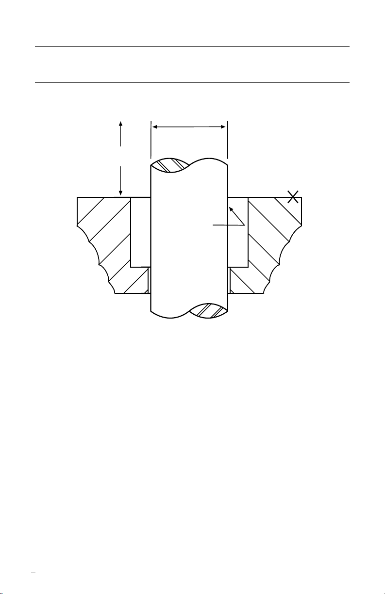
1.1 Refer to Figure 1 for shaft, sleeve and seal housing requirements.
Seal Chamber Requirements Figure 1
Shaft or sleeve OD
±0.025 mm
(±0.001 inch)
To rst
obstruction
Face of seal housing/vessel
to be square to the axis of
the shaft to within 0.5 mm
(0.020 inch) FIM and have
a 1.6 µm (√ 63 µinch) Ra
nish or better
• Bearings, drive, and coupling must be in good condition
• Maximum axial movement of shaft (end play) = 0.25 mm (0.010 inch) FIM
• Maximum combined shaft concentricity and shaft deection at face of housing
total = 03.8 mm (0.150 inch) FIM
1.2 Refer to assembly drawing included with seal package for specic seal design,
materials of construction, dimensions, and piping connections.
1.3 Check shaft or sleeve OD, box bore, and box depth to ensure that they are
dimensionally the same as shown on the seal assembly drawing.
1.4 Check gland pilot and bolt holes to ensure they are adaptable to the equipment and
are the same as shown on the assembly drawing.
1.5 Seal Faces: While all seal parts are manufactured to precise tolerances, the seal
faces (stationary and rotating face) are of primary importance. These two sealing
faces are lapped at to three light bands or better (34.8 millionths of an inch) and
polished. It is imperative that these two faces be handled with care and kept perfectly
clean.
1.6 Do not apply oil or other lubricants to the seal faces or to the secondary seals.
1.7 Lightly lubricate the rotating face gasket and the O-ring on seal drive ID with a
lubricant compatible with the application and elastomer materials.
2
Page 3

2 Installation
2.1 Install the two seat gasket O-rings furnished for the stationary face, one ring per side.
2.2 Install the stationary face into the gland ring with the sealing face rst so it will
protrude out the back of the gland ring.
2.3 Install the gland and stationary face over the shaft and ease it into position. Bolt the
gland ring to the face of the stufng box or seal housing by drawing the nuts down
evenly. The gland ring gasket is one of the seal gasket O-rings, therefore, there is no
concern for additional sealing elements in the area.
2.4 Install the sleeve gasket O-ring, into the O-ring groove of the seal drive assembly.
2.5 Install the rotating face gasket O-ring, on the rst step and against the second step
wall of the seal drive assembly.
2.6 Line up the slots on the rotating face OD with the drive pins in the seal drive
assembly and slide the rotating face into place on the seal drive assembly extension
surface.
2.7 Wipe the sealing faces of the rotating and stationary face clean.
Remember: Do not oil the sealing faces.
2.8 All outside VRA seal designs require that the rotating portion of the seal, seal drive
with seal ring, be slid on the shaft as an entire unit to prevent damage to the rotating
face. Slide the entire unit on the shaft until the stationary and rotating faces touch.
Remember: Do not touch the sealing face of the rotating face.
2.9 Set the seal to the distance given on the assembly drawing, furnished with the seal.
This dimension is shown on the assembly drawing as the distance from the face
of the equipment to the back of the seal drive. Make sure the spring gap is evenly
spaced around the seal and lock the seal drive to the shaft with the seal drive set
screws.
3 Operation Recommendations
3.1 The pressure acting on the seal must not exceed the pressure velocity rating of the
seal design and materials of construction.
3.2 If the seal runs hot, check for proper seal setting and seal housing dimensions to
insure that the seal is not over-compressed. Shut down the equipment immediately
if the seal gets hot.
3.3 When the gas being sealed is other than air, never start up the equipment without
properly venting.
3.4 This seal can be used if a full vacuum pressure condition exists.
For special problems encountered during installation, contact your nearest Flowserve Sales
and Service Representative or Authorized Distributor.
3
Page 4

TO REORDER REFER TO
flowserve.com
B/M #
F.O
.
4 Repair
This product is a precision sealing device. The design and dimension tolerances are critical
to seal performance. Only parts supplied by Flowserve should be used to repair a seal.
To order replacement parts, refer to the part code and B/M number. A spare backup seal
should be stocked to reduce repair time.
When seals are returned to Flowserve for repair, decontaminate the seal assembly and
include an order marked "Repair or Replace." A signed certicate of decontamination
must be attached. A Material Safety Data Sheet (MSDS) must be enclosed for any
product that came in contact with the seal. The seal assembly will be inspected and,
if repairable, it will be rebuilt, tested, and returned.
FIS131eng 03/13 Printed in USA
To find your local Flowserve representative
and find out more about Flowserve Corporation,
visit www.flowserve.com
Flowserve Corporation has established industry leadership in the design and manufacture of its products. When
properly selected, this Flowserve product is designed to perform its intended function safely during its useful life.
However, the purchaser or user of Flowserve products should be aware that Flowserve products might be used
in numerous applications under a wide variety of industrial service conditions. Although Flowserve can provide
general guidelines, it cannot provide specific data and warnings for all possible applications. The purchaser/user
must therefore assume the ultimate responsibility for the proper sizing and selection, installation, operation, and
maintenance of Flowserve products. The purchaser/user should read and understand the Installation Instructions
included with the product, and train its employees and contractors in the safe use of Flowserve products in connection
with the specific application.
While the information and specifications contained in this literature are believed to be accurate, they are supplied for
informative purposes only and should not be considered certified or as a guarantee of satisfactory results by reliance
thereon. Nothing contained herein is to be construed as a warranty or guarantee, express or implied, regarding any
matter with respect to this product. Because Flowserve is continually improving and upgrading its product design,
the specifications, dimensions and information contained herein are subject to change without notice. Should any
question arise concerning these provisions, the purchaser/user should contact Flowserve Corporation at any one of
its worldwide operations or offices.
© 2013 Flowserve Corporation
USA and Canada
Kalamazoo, Michigan USA
Telephone: 1 269 381 2650
Telefax: 1 269 382 8726
Europe, Middle East, Africa
Dortmund, Germany
Telephone: 49 231 69640
Telefax: 49 231 6964 248
Asia Pacific
Singapore
Telephone: 65 6544 6800
Telefax: 65 6214 0541
Latin America
Mexico City
Telephone: 52 55 5567 7170
Telefax: 52 55 5567 4224
 Loading...