

Page 1

VAPOPHONE
VKP 10
Operating Instructions 818427-00
Steam Trap Testing Equipment
1
Page 2

Contents
Page
Important Notes
Usage for the intended purpose ......................................................................................5
Safety note ......................................................................................................................5
Danger ............................................................................................................................ 5
Explanatory Notes
Scope of supply ..............................................................................................................6
Description ......................................................................................................................6
Function .......................................................................................................................... 6
Note ................................................................................................................................6
Technical Data ................................................................................................................. 7
Commissioning
Commissioning of display device ....................................................................................8
Operation
Checking steam trap .................................................................................................9, 10
Notice ............................................................................................................................11
Maintenance
Recharging battery ........................................................................................................11
Replacing battery ..........................................................................................................11
2
Page 3
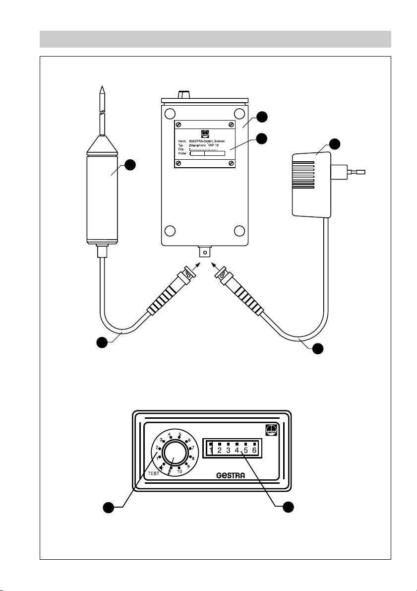
Parts Drawings
A
B
F
E
C
D
1
2
3
Page 4

Key
Display device
A
B
Name plate
C
Battery charger
D
Cable of battery charger
E
Cable of sound probe
F
Sound probe
1
Knob
2
Indicating meter
4
Page 5

Important Notes
Usage for the intended purpose
Use VKP 10 only for testing steam traps.
Safety note
The equipment must only be operated by qualified staff.
Qualified staff are those persons who – through adequate training in engineering, the
use and application of equipment in accordance with regulations concerning electrical
safety systems, and first aid & accident prevention – have achieved a recognised level
of competence appropriate to the commissioning and operation of this device.
Danger
Do not use the VKP 10 in areas subject to explosion hazards!
This presents the risk of severe injuries or death!
Do not touch live parts with the sound probe!
This presents the risk of severe cases of electric shock!
The tip of the sound probe has a sharp edge.
This presents a danger of cuts!
5
Page 6

Explanatory Notes
Scope of supply
The VAPOPHONE VKP 10 service case contains:
1 Display device
1 Sound probe
1 Leather bag
1 Storage battery (installed in the display device)
1 Battery charger with connecting cable for display device
1 Operating manual
Description
The steam trap testing equipment VKP 10 consists of a display device and a sound
probe.
The portable ultrasonic detector VKP 10 is designed for evaluating and testing steam
traps of all makes in order to detect steam losses and leaks.
Function
The testing equipment detects and evaluates ultrasonic vibrations caused by the
media flowing through the steam trap. The ultrasonic vibrations are transferred to the
tip of the sensor by pressing the sound probe to the specified point of reference on the
trap body. The ultrasonic vibrations are then converted into electric pulses and
indicated by the display device. The VAPOPHONE VKP 10 signals only vibrations
within 40 – 60 kHz, as these frequencies constitute the usual vibration range
associated with flowing steam. The user will evaluate the sensed ultrasonic vibrations
as part of the comparison measurement carried out for reference purposes.
Attention
■ Do not use the VAPOPHONE VKP 10 in areas subject to explosion
hazards!
■ The 9 V NiCd storage battery of the display device must only be
replaced by the manufacturer!
■ The sound probe VKPS 10 must only be used for sensing ultrasonic
vibrations at the surface of the steam trap bodies.
6
Page 7

Explanatory Notes continued
Technical Data
Display device
Plastic casing with knob and analogue indicator.
Casing with integrated storage battery compartment.
One socket to plug in the connecting cable of the sound probe.
Protection IP 41.
Max. admissible service temperature: 70°C.
Min. admissible service temperature: 0°C.
Power supply
The equipment is powered by the 9 V NiCd storage battery or by the power supply unit
that comes with the VKP 10.
Sound probe
The sound probe is powered by the storage battery of the display device.
Power supply unit
230V/ 50Hz (other PSU available on request)
Output 12 V
Weight
Service case with equipment approx. 2 kg
Dimensions
Leather bag: 200 mm / 190 mm / 90 mm
Display device: 90 mm / 45 mm / 160 mm
(width / height / depth)
7
Page 8

Commissioning
Commissioning of display device
The equipment can be used for testing tasks with or without the leather bag.
When using the leather bag, please open the strap at the bottom of the bag to uncover
the cable entry.
■ Connect the cable of the sound probe to the display device .
■ Check the charging capacity of the storage battery.
Set the knob to the battery-check position .
If the indicator shows a value below “5”, re-charge the storage battery.
1
2
E A
8
Page 9

Operation
Steam trap testing
Before carrying out steam trap tests ajust the measuring sensitivity of the VKP 10 by
using the knob . The highest sensitivity is obtained when the knob is set to “10”.
1
Note that different steam trap types produce – under identical conditions and with
same loss of steam – different sound levels. For GESTRA steam traps type BK we
recommend the knob setting “8”, and for steam traps type MK the knob setting “7”.
Press the probe tip gently onto the trap surface. When testing traps of the same type
make sure you always apply the probe at the same point of the trap body in order to
be able to compare the results more easily and to discover changes when repeating
the tests.
Steam traps operating continuously and discharging up to about 30 kg/hr (66 lb/hr) of
condensate from steam pressures lower than 20 bar (290 psi) will cause no or only a
slight deflection of the indicating meter. Any steam loss is indicated by a proportional
meter deflection. The relation between steam loss and meter deflection depends on
the steam trap type and the used measuring point on the trap surface. Larger
condensate flowrates and higher service pressures result in louder flow-generated
noises, making it necessary to reduce the sensitivity setting. To obtain meaningful
readings when using the VKP 10, log and use installation-specific survey data and
empirical test values.
In practice an exact quantification of the steam loss is usually only of minor
importance. Normally an approximate value that allows the detection of steam loss
through steam traps at a tolerable effort will suffice.
When checking the steam traps set the knob to “7” or “8”. A continuous indication
between 4 and 5 on the meter scale indicates that the trap requires maintenance or
replacement. Meter deflections between 4 and 5 indicate steam losses of 1 kg/hr up to
4 kg/hr.
When testing conventional steam trap bodies apply the probe at right angles
to the cover of the trap.
9
Page 10

Operation continued
Steam trap testing continued
Float traps: Apply the probe at right angles to the trap body.
GESTRA Steam traps RHOMBUS
Attention
■ If traps of the same type are tested take care that the probe is always
applied at the same point of the trap body in order to be able to
compare the results obtained and also to discover changes when
repeating the test.
10
line
: Apply the tip of the probe laterally to the trap body.
Page 11

Operation continued
Notice
■ Please take into account that ultrasonic sources, such as pumps or steam reducing
stations, in the proximity of the steam trap to be tested might falsify the result. In
this case “steam loss” might be indicated even though the traps operate correctly.
This can be verified by scanning the adjacent pipelines. If the reflection remains
unchanged or increases, this must be attributed to a foreign ultrasonic source. If
possible switch off sound emitting plant components.
■ Intermittently operating steam traps cause recurrent meter deflections which might
even reach the end of the scale. Thermostatic traps (with bimetallic control or
membrane regulators) may operate within the specified pressure and flowrate
range either continuously or intermittently. In this case steam loss can usually be
excluded. A recurrent meter deflection indicates here correctly operating steam
traps.
■ Thermodynamically controlled steam traps always operate intermittently over the
complete flowrate range and might thereby cause steam loss which rises with
increasing lift frequency. A clear evidence of loss is only given by a constantly large
meter deflection.
■ Basically the same considerations as mentioned for thermodynamic traps also
apply in the case of steam traps with open floats. However, with float-operated traps
inherent steam loss will definitely occur even when the trap operates intermittently.
■ Before performing the tests at least an estimation should be carried out with the aid
of technical plant data (service pressures, differential pressures, flowrates etc.) so
as to ascertain whether the trap flowrate lies within the range that permits testing.
Maintenance
Recharging battery
Plug the battery charger into the display device . The red and the green LED of
C
the battery charger light up: red = charging.
For a full charge leave the charger plugged into the mains supply for approx. 14 hours.
Replacing battery
Under normal operating conditions the integrated battery has a service life of 5 to 7
years. Should the battery be faulty, please return the equipment to GESTRA GmbH in
Bremen for replacement.
Attention
■ Note that the 9 V NiCd battery of the display device must only be
replaced by the manufacturer!
A
11
Page 12

GESTRA Gesellschaften · GESTRA Companies · Sociétés GESTRA · Sociedades Gestra · Società GESTRA
Vertretungen weltweit · Agencies all over the world · Représentations dans le monde entier · Representaciones en todo el mundo · Agenzie in tutto il mondo
Great Britain
Flowserve Flow Control (UK) Ltd.
Burrel Road, Haywards Heath
West Sussex RH 16 1TL
Tel. 00 44 14 44 / 31 44 00
Fax 00 44 14 44 / 31 45 40
E-mail: sales@flowserve.com
France
Flowserve Flow Control S.A. S.
10 Avenue du Centaure, BP 8263
F-95801 CERGY PONTOISE CEDEX
Tél. 0 03 31/ 3443 26 60
Fax 00331/34432687
E-mail: gnation@flowserve.com
España
GESTRA ESPAÑOLA S.A.
Luis Cabrera, 86-88
E-28002 Madrid
Tel. 00 3491 /5 152 032
Fax 003491/4136747; 5152036
E-mail: gestra@gestra.es
Italia
Flowserve S.p. A
Divisione Italgestra
Via Prealpi, 30 – 20032 Cormano (MI)
Tel. 00 3902 /66 3251
Fax 00 39 02/ 66 32 55 60
E-mail: infoitaly@flowserve.com
Portugal
Flowserve Portuguesa, Lda.
Av. Dr. Antunes Guimarães, 1159
Porto 4100-082
Tel. 0035122/6198770
Fax 003 51 22/ 61075 75
E-mail: gestra@gestra.pt
®
GESTRA GmbH
P. O. Box 10 54 60, D-28054 Bremen, Münchener Str. 77, D-28215 Bremen
Tel. ++49 (0) 421 35 03 - 0, Fax ++49 (0) 421 35 03- 393
E-Mail gestra.gmbh@flowserve.com, Internet www.gestra.de
A Unit of Flowserve Corporation
818427-00/104cm · © 2003 GESTRA GmbH · Bremen · Printed in Germany
12
 Loading...