

Page 1

Valtek VL-C Spring Cylinder
Linear Actuators
GENERAL INFORMATION
The following instructions are designed to assist in
installing, troubleshooting and servicing Valtek VL-C
spring cylinder linear actuators sizes 100, 150 and 200.
Separate installation, operation and maintenance
instructions cover 25 and 50 sizes as well as additional
features (such as handwheels, limit stops, fail-safe
systems or limit switches). Product users and maintenance personnel should thoroughly review this bulletin
prior to installing, operating or disassembling the
actuator.
This publication does not contain information on
Flowserve positioners. Refer to the appropriate installation operation and maintenance instructions for installing, maintaining, troubleshooting, calibrating and
operating Flowserve positioners.
To avoid possible injury to personnel or damage to valve parts, WARNING and CAUTION
notes must be strictly followed. Modifying this
product, substituting non-factory or inferior
parts or using maintenance procedures other
than outlined could drastically affect performance, void product warranties and be hazardous to personnel and equipment.
WARNING: Standard industry safety practices must
be followed when working on this or any process
control product. Specifically, personal protection
and lifting devices must be used as warranted.
Unpacking
While unpacking the actuator, check packing list against
materials received. Lists describing the actuator and
accessories are included in each shipping container.
1. Position the lifting straps and hoist to avoid damage
to the tubing and mounted accessories when lifting
the actuator from the shipping container.
WARNING: When lifting an actuator with lifting
straps through the yoke legs, be aware the
center of gravity may be above the lifting point.
Therefore, support must be given to prevent the
actuator from rotating or causing serious injury
to personnel or damage to nearby equipment.
2. Contact your shipper immediately in the event of
shipping damage.
3. Contact your Flowserve representative with any
problems.
Flowserve Corporation, Valtek Control Products, Tel. USA 801 489 8611
Valtek No. 188485
54-1
Page 2

Installation
Prior to installation, make sure adequate overhead
clearance for the actuator is provided to allow for proper
removal from the valve body and for proper maintenance. Refer to Table I.
Table I:
Overhead Clearance for Maintenance
Actuator Size Minimum Clearance
100, 150, 200 9 inches
NOTE: If an actuator is attached to a valve body
assembly, see the appropriate installation, operation,
maintenance instructions.
1. Connect the air supply and instrument signal air
lines to the two marked connections on the
positioner. Since both the cylinder and positioner
are suitable for 150 psi (10.3 bar) air supply, an air
regulator should not be used unless the supply
exceeds 150 psi (10.3 bar).
NOTE: In some cases, air supply must be limited to
100 psi (6.9 bar) rather than 150 psi (10.3 bar); this
will be indicated by a sticker found near the upper
air port on the cylinder.
WARNING: To avoid personal injury or equipment damage, do not exceed recommended
supply pressure.
2. Installation of an air filter on the supply line is
recommended.
3. Use a soap solution to make sure all air connections
are leak-free.
MAINTENANCE
At least once every six months, check for proper operation by following the preventative maintenance steps
outlined below.
while the actuator is in service.
suspected with the actuator, refer to the
and Reassembly
WARNING: To avoid serious injury, the following
steps should only be performed with the air supply
or positioner input disconnected.
1. When disconnecting air supply, observe actuator
for correct fail-safe action.
2. Examine the actuator for damage caused by corrosive fumes and process drippings.
3. Clean the actuator and repaint any areas of severe
oxidation.
4. If possible, stroke the actuator and check for
smooth, full-stroke operation.
WARNING: To avoid serious injury, keep hands,
hair and clothing away from all moving parts
while operating the actuator.
These steps should not be performed
If an internal problem is
Disassembly
section.
5. Make sure positioner mounting bolts, linkage and
stem clamp are fastened securely.
6. Ensure all accessories, brackets and associated
bolting are fastened securely.
7. Check rubber bellows for wear.
8. Spray soap solution around the base and top of the
cylinder, the adjusting screw and the lower actuator
stem bushing to check for air leaks through the
O-rings and gasket.
9. Clean any dirt or foreign material from the actuator
stem.
10. If an air filter is supplied, isolate the air filter, then
check and replace cartridge as necessary.
DISASSEMBLY AND REASSEMBLY
Disassembling the Actuator
Refer to Figures 1 through 4 to disassemble the cylinder
actuator.
1. Shut off air supply. If actuator is installed on a
Flowserve valve, remove the valve per the appropriate installation operation, maintenance instructions.
WARNING: To avoid serious injury, depressurize the line to atmospheric pressure and drain
all fluids before working on the actuator.
2. Disconnect all tubing. Remove stem clamp and
stem bellows from the actuator stem.
3. Relieve spring compression by completely removing the adjusting screw. Remove adjusting screw
gasket from adjusting screw.
WARNING: To avoid serious personal injury,
relieve the spring compression before further
disassembly. The cylinder end cap may fly off
the yoke when removing the cylinder tie-rod
nuts.
4. Remove the four self-locking tie rod nuts by unscrewing in an alternating pattern. Remove the
cylinder end cap.
5. Lift the cylinder off the yoke and piston. If excessive
O-ring resistance is felt, use a rubber mallet to
gently tap around the cylinder perimeter.
WARNING: To avoid serious personal injury, do
not use air pressure to remove the cylinder. The
cylinder may fly off the yoke.
CAUTION: When removing the actuator stem
lock nut, do not hold the actuator stem with a
pipe wrench as the sealing surface may be
damaged; instead, use a wrench on the flats of
the actuator stem.
6. For air-to-retract configurations, remove the
spring(s) and spring button for cleaning and inspection (see Figures 1, 3 and 4). Remove the actuator
54-2
Flowserve Corporation, Valtek Control Products, Tel. USA 801 489 8611
Page 3
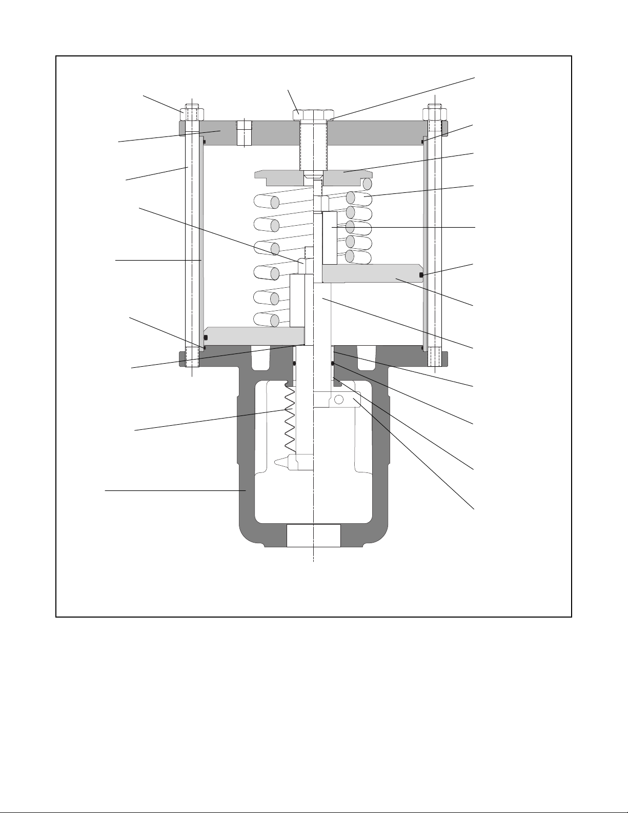
Tie Rod Nut (4)
(Item No. 205)
End Cap
(Item No. 207)
Tie Rod (4)
(Item No. 206)
Actuator Stem
Lock Nut
(Item No. 348)
Adjusting Screw
(Item No. 210)
Adjusting Screw
Gasket
(Item No. 248)
End Cap O-ring
(Item No. 227)
Spring Button
(Item No. 227)
Spring
(Item No. 229)
Stem Spacer
(Item No. 228)
Cylinder
(Item No. 202)
Yoke O-ring
(Item No. 271)
Piston Stem
O-ring
(Item No. 272)
Stem Bellows
(Item No. 247)
Yoke
(Item No. 201)
Quad-seal
(Item No. 271)
Piston
(Item No. 225)
Actuator Stem
(Item No. 211)
Bushing
(Item No. 253)
Actuator Stem
O-ring
(Item No. 275)
Bushing
(Item No. 253)
Stem Clamp
No. 26906
(Valtek Positioner)
Figure 1: Air-to-retract Cylinder Actuator
NOTE: Item numbers correspond directly to actuator's bill of material. Refer to it for specific part numbers.
stem locknut by holding the flats on the actuator
stem and slide the piston and stem spacer off the
actuator stem. The spring guide should be removed
when using dual or heavy-duty spring designs.
NOTE: The dual spring configuration (Figure 3) has
two springs, one inside the other. Remove both
springs during this step.
7. For air-to-extend configurations, slowly loosen and
remove the actuator stem locknut and piston.
Flowserve Corporation, Valtek Control Products, Tel. USA 801 489 8611
(Remove the piston and stem locknut together,
making sure the piston does not bind on the actuator stem.) Next, remove the spring button, spring
and stem spacer.
WARNING: To avoid personal injury, be certain
the spring force is completely relieved before
removing actuator stem locknut.
8. Remove the piston quad-seal, piston stem O-ring
and yoke O-ring.
54-3
Page 4

Spring Button
(Item No. 227)
Spring
(Item No. 229)
Stem Spacer
(Item No. 228)
Figure 2: Air-to-extend Cylinder Actuator
NOTE: Item numbers correspond directly to actuator's bill of material. Refer to it for specific part numbers.
Parts listed change location upon reversing air action. No new parts are required.
9. Remove the actuator stem O-ring.
NOTE: The stem bushing is pressed into the yoke.
The actuator stem O-ring can be replaced without
removing the bushing.
10. Use an appropriately sized press to push a worn or
damaged bushing out of the yoke.
Reassembling the Actuator
To reassemble the cylinder actuator, refer to Figures 1
through 4:
54-4
1. All O-rings and the quad-seal should be replaced
and lubricated with a calcium complex grease
(DuBois MPG-2 or equivalent). Silicone O-rings
must be lubricated with Magnalube-G lubricant or
equivalent.
2. Thoroughly clean all internal parts before beginning
assembly. Check the cylinder bore for scratches,
pitting or worn areas. Lubricate cylinder wall and all
internal surfaces with the appropriate lubricant.
NOTE: Applying a light coating of lubricant to the
Flowserve Corporation, Valtek Control Products, Tel. USA 801 489 8611
Page 5

Adjusting Screw
(Item No. 210)
Outer Spring
(Item No. 229)
Inner Spring
(Item No. 230)
Spring Button
(Item No. 227)
Spring Guide
(Item No. 326)
Actuator Stem
(Item No. 211)
Figure 3: Dual-spring Cylinder Actuator
NOTE: Item numbers correspond directly to actuator's bill of material. Refer to it for specific part numbers.
Parts listed indicate differences from the single-spring model.
entire cylinder bore, end cap and both sides of the
piston enables smooth operation and can help
reduce corrosion.
3. Lubricate the outside of the replacement bushing if
the stem bushing has been removed. Press a new
lower stem bushing into the actuator stem bore in
the yoke until it bottoms out. Press the upper stem
bushing into the bore until it is flush with the top of
the yoke (refer to Figures 1 or 2).
4. Replace the actuator stem O-ring and yoke O-ring.
Flowserve Corporation, Valtek Control Products, Tel. USA 801 489 8611
NOTE: When installing the actuator stem, align the
actuator stem flats with the yoke legs. This allows
the stem clamp to work properly and helps prevent
plug assembly rotation.
CAUTION: When installing the actuator stem
lock nut, do not hold the actuator stem with a
pipe wrench as the sealing surface may be
damaged; instead, use a wrench on the flats of
the actuator stem.
5. Reassemble the piston, piston stem O-ring and
54-5
Page 6

stem spacer on the actuator stem according to the
proper air-action (see either Figure 1 or 2). Replace
the piston quad-seal. Air-to-extend configurations
require the spring button to be stored under actuator stem locknut. Tighten the locknut firmly by
holding the flats on the actuator stem.
NOTE: When reassembling dual or heavy-duty
spring actuators, the spring guide must be first
inserted under the actuator stem locknut (see Figures 3 and 4).
6. For air-to-extend configurations, place the spring
under the piston and insert the actuator stem
through the yoke, being careful not to pinch the
actuator stem O-ring or gall the stem and stem
bushing. For air-to-retract configurations, insert the
actuator stem through the yoke and place the
spring(s) and spring button above the piston.
7. Install the tie rods into the yoke using Loctite
No. 242 NSF61 or equivalent.
Table II: Tie Rod Nut Torque Values
Actuator Size Torque Value (ft.-lbs.)
100 207 – 229
150, 200 336 – 371
12. Reinstall the stem bellows and stem clamp.
NOTE: To ensure maximum clamping strength
when installing the stem clamp, make sure the stem
clamp bolting is perpendicular to one of the slots
machined into the actuator stem.
13. Apply air over the piston. Tighten the stem clamp
bolting with the stem clamp adjusted to point at the
closed position of the stroke indicator plate.
NOTE: If the actuator is installed on a Flowserve
valve, refer to the appropriate installation, operation, maintenance instructions for correct plug stem
thread engagement.
14. Reconnect tubing, supply and signal lines.
8. Install the cylinder, making sure the cylinder is
completely seated on the yoke. Care should be
taken not to scar or cut the piston and yoke O-rings.
9. Replace the cylinder end cap and secure to the tie
rods using new self-locking nuts. Refer to Table II
for the appropriate torque values.
WARNING: To avoid personal injury, the cylinder end cap must be solidly in place. The cylinder end cap may fly off when pressurized.
10. Reinstall the adjusting screw fitted with a new
adjusting screw gasket.
NOTE: Be certain the hole in the spring button is
directly centered under the adjusting screw hole in
the cylinder on air-to-retract configurations.
11. Tighten the adjusting screw enough to provide an
air seal with the gasket. Do not overtighten.
Reversing the Air-action
To change the air action from air-to-retract to air-to
extend, or vice versa, refer to Figures 1, 2 or 4:
NOTE: Dual spring actuators are not reversible.
1. Disassemble the actuator according to the
sembling the Actuator
2. For air-to-retract action, reassemble the actuator
with stem spacer and spring button over the piston.
3. For air-to-extend action, reassemble with spring
and stem spacer below the piston and with the
spring button stored above the piston.
4. Reassemble the actuator according to the
sembling the Actuator
5. The positioner must also be reversed. See the
appropriate positioner maintenance instructions.
section.
section.
Disas-
Reas-
54-6
Flowserve Corporation, Valtek Control Products, Tel. USA 801 489 8611
Page 7

AIR-TO-
RETRACT
Spring Button
(Item No. 227)
Adjusting Screw
(Item No. 210)
Adjusting Screw Gasket
(Item No. 248)
Tie Rod Nut (4)
(Item No. 205)
Tie Rod (4)
(Item No. 206)
End Cap
(Item No. 207)
End Cap O-ring
(Item No. 208)
Actuator Stem Nut
(Item No. 348)
AIR-TO-
EXTEND
Spring
(Item No. 229)
Actuator Stem Nut
(Item No. 348)
Stem Spacer
(Item No. 228)
Quad-seal
(Item No. 271)
Piston
(Item No. 225)
Piston Stem O-ring
(Item No. 272)
Actuator Stem
(Item No. 211)
Actuator Stem O-ring
(Item No. 275)
Cylinder
(Item No. 202)
Upper Stem
Bushing
(Item No. 253)
Lower Stem Bushing
(Item No. 253)
Spring Button
(Item No. 227)
Quad-seal
(Item No. 271)
Piston
(Item No. 225)
Piston Stem O-ring
(Item No. 272)
Stem Spacer
(Item No. 228)
Actuator Stem
(Item No. 211)
Spring
(Item No. 229)
Stroke Plate
(Item No. 213)
Figure 4: Exploded View, Spring Cylinder Actuator
NOTE: Item numbers correspond directly to actuator's bill of material. Refer to it for specific part numbers.
Flowserve Corporation, Valtek Control Products, Tel. USA 801 489 8611
Yoke O-ring
(Item No. 274)
Yoke
(Item No. 201)
Stem Bellows
(Item No. 247)
54-7
Page 8

Troubleshooting
Problem Probable Cause Corrective Action
High air consumption or 1. Leaks in the air supply or instru- 1. Tighten connections and replace any
leakage ment signal system leaking lines
2. Malfunctioning positioner 2. Refer to appropriate positioner
maintenance bulletin
3. Leaks through O-rings or adjusting 3. Replace O-rings or gasket
screw gasket
Actuator does not move to 1. Air pressure in cylinder not venting 1. Refer to appropriate positioner
fail position upon loss because of faulty positioner maintenance bulletin
of air supply pressure 2. Spring failure 2. Replace spring
3. Internal valve problem 3. Refer to valve’s maintenance bulletin
Jerky or sticking 1. Insufficient air supply pressure 1. Check air supply and any filters or
stem travel regulators; check for leaking O-rings
2. Unlubricated cylinder wall 2. Lubricate cylinder wall with silicone
lubricant
3. Worn or damaged stem bushings 3. Check actuator stem for damage;
replace actuator stem, O-ring, and
stem bushings, if necessary
4. Improperly assembled spring 4. Disassemble actuator and check
cylinder and piston for damage;
reassemble actuator correctly
5. Internal valve problem 5. Refer to valve’s maintenance
instructions
Flowserve Corporation has established industry leadership in the design and manufacture of its products. When properly selected, this
Flowserve product is designed to perform its intended function safely during its useful life. However, the purchaser or user of Flowserve products
should be aware that Flowserve products might be used in numerous applications under a wide variety of industrial service conditions. Although
Flowserve can (and often does) provide general guidelines, it cannot provide specific data and warnings for all possible applications. The
purchaser/user must therefore assume the ultimate responsibility for the proper sizing and selection, installation, operation and maintenance
of Flowserve products. The purchaser/user should read and understand the Installation Operation Maintenance (IOM) instructions included with
the product, and train its employees and contractors in the safe use of Flowserve products in connection with the specific application.
While the information and specifications presented in this literature are believed to be accurate, they are supplied for informative purposes only
and should not be considered certified or as a guarantee of satisfactory results by reliance thereon. Nothing contained herein is to be construed
as a warranty or guarantee, express or implied, regarding any matter with respect to this product. Because Flowserve is continually improving
and upgrading its product design, the specifications, dimensions and information contained herein are subject to change without notice. Should
any question arise concerning these provisions, the purchaser/user should contact Flowserve Corporation at any of its worldwide operations
or offices.
For more information, contact:
Flowserve and Valtek are registered trademarks of Flowserve Corporation.
For more information about Flowserve and its products,
contact www.flowserve.com or call USA 972 443 6500
Regional Headquarters
1350 N. Mt. Springs Prkwy.
Springville, UT 84663
Phone 801 489 8611
Facsimile 801 489 3719
12 Tuas Avenue 20
Republic of Signapore 638824
Phone (65) 862 3332
Facsimile (65) 862 4940
12, av. du Québec, B.P. 645
91965, Courtaboeuf Cedex, France
Phone (33 1) 60 92 32 51
Facsimile (33 1) 60 92 32 99
Quick Response Centers
5114 Railroad Street
Deer Park, TX 77536 USA
Phone 281 479 9500
Facsimile 281 479 8511
104 Chelsea Parkway
Boothwyn, PA 19061 USA
Phone 610 497 8600
Facsimile 610 497 6680
1300 Parkway View Drive
Pittsburgh, PA 15205 USA
Phone 412 787 8803
Facsimile 412 787 1944
54-8
FCD VLAIM054-00 © 2001 Flowserve Corporation. Flowserve Corporation, Valtek Control Products, Tel. USA 801 489 8611
Flowserve Corporation, Valtek Control Products, Tel. USA 801 489 8611
 Loading...