

Page 1

GESTRA Steam Systems
VKP 40Ex
VKP 40
Operating instructions 81853501
Steam Trap Testing, Recording & Evaluating System TRAPtest VKP 40 (VKP 40Ex for applications
in potentially explosive areas) for checking steam traps of all types and makes for steam loss
and banking-up of condensate
1
Page 2

2
Contents
Description
System description VKP 40Ex, VKP 40 ..................................................................................................................................................... 3
Application VKP 40Ex, VKP 40 ................................................................................................................................................................. 3
Scope of supply VKP 40Ex, VKP 40 .......................................................................................................................................................... 3
Safety Notes for VKP 40Ex
Notes .................................................................................................................................................................................................. 4, 5
Application ............................................................................................................................................................................................ 5
Maintenance notes VKPN 40Ex; VKPS 40Ex ............................................................................................................................................. 5
Replacing storage battery unit of VKPN 40Ex ....................................................................................................................................... 5, 6
Environmental requirements ................................................................................................................................................................... 6
Technical Data VKP 40Ex, VKP 40
System requirements .............................................................................................................................................................................. 7
Data collector VKPN 40Ex, VKPN 40 ........................................................................................................................................................ 7
Measuring transducer VKPS 40Ex ........................................................................................................................................................... 7
Connecting cable for VKPA 40 .................................................................................................................................................................7
Test duration ........................................................................................................................................................................................... 7
Dimensions of weights ............................................................................................................................................................................ 8
Charging storage batteries of VKPN 40Ex, VKP 40 .................................................................................................................................. 8
Replacing storage batteries VKPN 40 (for VKPN 40Ex see section “Safety Notes”) ...................................................................................9
Maintaining VKP 40 ................................................................................................................................................................................. 9
Spare parts ............................................................................................................................................................................................. 9
Connecting and Commissioning Data Collector VKPN 40Ex, VKPN 40
Connecting data collector VKPN 40Ex or VKPN 40 to a PC ..................................................................................................................... 10
Connecting measuring transducer VKPS 40Ex to data collector VKPN 40Ex or VPKN 40 ......................................................................... 10
Commissioning data collector VKPN 40Ex or VKPN 40 ........................................................................................................................... 11
Switching off data collector ................................................................................................................................................................... 12
Automatic de-activation ........................................................................................................................................................................ 12
TRAPtest software PC programm
Installing PC software ........................................................................................................................................................................... 13
Starting and quitting program ............................................................................................................................................................... 13
Deinstalling PC software ....................................................................................................................................................................... 13
Software menus at a glance ........................................................................................................................................................... 13, 14
Data Exchange between PC and Data Collector VKPN 40Ex or VKPN 40
VKPN 40Ex or VKPN 40 ......................................................................................................................................................................... 15
Checking Steam Traps
Test ............................................................................................................................................................................................. 16 – 18
Test measurement ................................................................................................................................................................................ 19
Foreign noise ........................................................................................................................................................................................ 20
Reference points for measurement ................................................................................................................................................. 20, 21
Fault finding list for troubleshooting
Data collector VKPN 40Ex, VKPN 40 ...................................................................................................................................................... 22
Measuring transducer VKPS 40Ex ......................................................................................................................................................... 22
Screen display on PC ............................................................................................................................................................................ 22
EC Type Approval
EC type approval ................................................................................................................................................................................... 23
Page 3

Description
System description VKP 40Ex, VKP 40
The steam trap testing system consists of the data collector VKPN 40Ex or VKPN 40, the measuring transducer VKPS 40Ex and
the software for data management on the PC. The VKPN 40Ex / VKP 40 can check and evaluate all types and makes of steam traps
for loss of live steam and banking-up of condensate.
The diagnostic system detects and analyses ultrasonic vibrations on the trap body caused by live steam flowing through the stream
trap. The ultrasonic vibration is transmitted through the trap body and picked up by the hand-held probe by pressing the sensor tip
onto a point of the trap body that is characteristic of the respective trap type. The ultrasonic vibration is then converted into electric
pulses and – in the form of digital signals – fed via cable to the data collector VKPN 40Ex or VKPN 40. The display of the data collector
shows the signals received during the test as a standing curve. With this graphical representation one can see at once whether the
tested steam trap is working with or without loss of steam. The recorded ultrasonic vibration is analysed by the data collector and
evaluated in accordance with certain empirically ascertained limit values that depend on the trap type. During the test the temperature
of the steam trap is measured, too. Provided that a service pressure has been specified (on the PC), the diagnostic system identifies
blocked steam traps that cause banking-up of condensate. .
If the annual operating hours and the steam costs have been entered in the system, the software can calculate the financial loss
caused by faulty steam traps. To quantify the steam loss caused by faulty steam traps, empirically obtained test values are used as
reference.
All curves recorded for a steam trap as well as the associated numerical test results and the corresponding analysis by the system can
be stored and printed out.
For more detailed information on the system and its functions refer to the “Online Documentation” of the TRAPtest
PC program.
Application VKP 40Ex, VKP 40
■ Use VKP 40Ex / VKP 40 only for testing steam traps!
For more information on the test procedure see section “Checking Steam Traps”.
■ Use the equipment only on voltagefree and earthed pipe systems! Mortal danger is imminent if you carry out
measurements on voltagecarrying objects.
■ In explosionrisk areas only the measuring transducer VKPS 40Ex connected via cable with the data collector
VKPN 40Ex may be used.
Attention
■ Do not connect the data collector to or disconnect it from the measuring transducer
in these areas!
For more information see section “Safety Notes for VKP 40Ex”!
Scope of supply VKP 40Ex, VKP 40
The carrying case TRAPtest VKP 40Ex / VKP 40 contains:
1 Hand-held data collector (probe) VKPN 40ex / VKPN 40
1 Measuring transducer VKPS 40ex / VKPS 40
1 Connecting cable VKPA 40 incl. power supply unit and connecting cable with serial connector for PC
3 Adaptor plugs for international application of the power supply unit
1 Strap for data collector
1 Holster for measuring transducer
1 TRAPtest software on CD Rom
1 Operating manual
3
Page 4
4
Safety Notes for VKP 40Ex
This section of the operating manual refers to the handheld data collector VKPN 40Ex, the measuring transducer VKPS 40Ex and
the connecting cable VKPA 40.
■ The connecting cable VKPA 40 must not be used in explosionrisk areas!
Notes
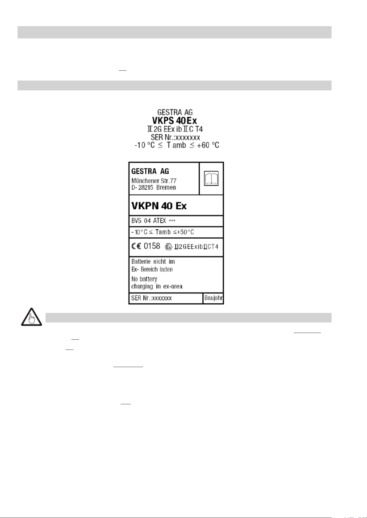
The equipment to be used in explosionrisk areas bears the following labelling:
Measuring transducer VKPS 40Ex:
Data collector VKPN 40Ex:
Attention
■ The data collector VKPN 40Ex and the measuring transducer VKPS 40Ex are connected via cable. This connection
must not be opened when the equipment is used in an explosionrisk area.
■ Do not open the data collector VKPN 40Ex and the measuring transducer VKPS 40Ex in explosionrisk areas!
■ In case of visible signs of damage or malfunctions take the data collector VKPN 40Ex and the measuring
transducer VKPS 40Ex immediately out of the explosionrisk area.
■ Tests must only be carried out by specially trained personnel and on voltagefree test objects.
The data collector VKPN 40Ex is provided with a storage battery for power supply.
.
■ The storage battery must only be charged outside the explosionrisk area with the aid of the
connecting cable VKPA 40.
The display of the data collector VKPN 40Ex shows the current battery charge. If the charging process takes extremely long or a
full charge cannot be obtained, the storage battery might have a malfunction and should therefore no longer be used but must be
replaced. Note that only a genuine GESTRA storage battery with protective circuit breaker must be used as replacement. For more
information on how to change the battery of the VKPN 40Ex see section “Replacing storage battery unit”.
Page 5
Safety Notes for VKP 40Ex – continued –
Notes – continued –
If the battery is sufficiently charged for the planned steam trap testing, the data collector VKPN 40Ex can be unplugged from the
connecting cable. Before entering the explosion-risk area connect the measuring transducer VKPS 40Ex to the data collector VKPN
40Ex. The connection between the data collector VKPN 40Ex and the measuring transducer VKPS 40Ex must not be opened in an
explosion-risk area.
The equipment can be carried into the explosion-risk area when it is switched on and when it is switched off.
Application VKP 40Ex
■ Use VKP 40Ex only for checking steam traps!
■ Use the equipment only on voltagefree pipe systems. Mortal danger is imminent if you carry out measurements on
voltagecarrying objects.
For more information on the test procedure refer to section “Checking steam traps”.
Maintenance notes VKPN 40Ex, VKPS 40Ex
In case of visible signs of damage (e. g. cracks in the casing, faulty display, worn down probe tip, …) do not use the
equipment in explosionrisk areas. Please contact GESTRA AG or a GESTRA company in your country.
The equipment is provided with a storage battery. To change this battery the equipment must be opened. Only trained personnel
conversant with the explosion protection directive is allowed to perform the replacement. Only genuine GESTRA replacement parts
must be used.
Attention
■ When opening the equipment make sure that neither the connecting cable VKPA 40 nor the measuring
transducer VKPS 40Ex is connected.
■ Do not open the equipment in explosionrisk areas! To prevent damage to electronic components shield the
equipment against electrostatic discharges (e.s.d).
■ Any type of work on the equipment – apart from replacing the storage battery – must only be
performed by GESTRA AG.
When used for its intended purpose the diagnostic system is maintenance-free. However, we recommend that the system should be
sent to GESTRA AG Bremen every 5 years for a general inspection.
Replacing storage battery unit VKPN 40Ex
Attention
■ Make sure that the data collector is switched off before replacing the rechargeable battery!
■ Save data before replacing the storage battery in order to avoid loss of data.
■ Make sure that the data collector is not connected via connecting cable VKPA 40 when replacing the
rechargeable battery.
■ Incorrect charge levels are indicated after the replacement of the storage battery unit.
It takes two charging/discharging processes before the correct state of charge can be indicated.
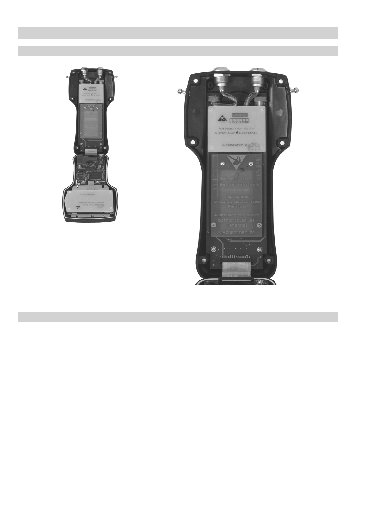
The storage battery must be replaced when its charging capacity is no longer sufficient for the required test tasks. For this purpose
remove the 6 screws from the bottom of the equipment. Detach the upper part of the equipment from the lower part.
Attention: The upper part is connected to the lower part via a ribbon cable. This cable connection must not be detached.
The storage battery unit is embedded with protective elements on a green board. This unit is fixed to the bottom of the equipment by
means of 4 screws. In order to exchange the battery this whole unit has to be replaced by a genuine GESTRA AG spare part.
Undo the 4 screws and remove the battery unit. Put the new battery unit onto the two centric items of the connector. Insert the
4 screws (M 2.5, M 3) and fasten them moderately. Then mount the two halves of the equipment together, making sure that the
gasket is properly inserted and the ribbon cable is not jammed between the two equipment parts. Then mount the 6 casing
screws and tighten them with a torque of 0.8 Nm. The battery can now be charged as described in section “Charging storage
batteries”. Note that the full performance of a new storage battery is achieved only after about 5 complete charge and discharge
cycles. Environmental regulations have to be taken into account when disposing of storage batteries.
5
Page 6
6
Safety Notes for VKP 40Ex – continued –
Replacing storage battery unit of VKPN 40Ex – continued –
Gasket
➞
➞
Board with storage
battery unit
Data collector VKPN 40Ex (opened)
Environmental requirements
Temperature rating for VKPN 40Ex:
Operating temperature: –10 °C to 50°C
Temperature rating for VKPS 40Ex:
Operating temperature: –10°C to 60°C
The equipment approval corresponds to protection class “II 2G EEX ib IIC T4”:
Explosion group IIc
GAS
Category 2
Temperature class T4
Intrinsically safe according to “ib”
➞
Ribbon cable
Lower part of VKPN 40Ex
Max. operating voltage:
Data collector VKPN 40Ex: 3.3 V
Measuring transducer VKPS 40Ex: 5.0 V
Max. power consumption:
Data collector VKPN 40Ex: 0.25 A
Measuring transducer VKPS 40Ex: 0.03 A
Page 7

Technical Data VKP 40Ex, VKP 40
System requirements
Operating system:
Windows 98, 2000, NT 4 (SP6) XP.
CD ROM drive
Minimum requirements
Computer with Pentium® compatible processor with 700 MHz
100 MB free hard disk memory
128 MB RAM
800 x 600 screen resolution
Recommended:
Computer with Pentium® compatible processor with 1.2 GHz
200 MB free hard disk memory
256 MB RAM
Data collector VKPN 40Ex, VKPN 40
Plastic casing with backlit display. Illumination can be switched on and off.
Illumination switches off automatically after 10 sec. if no key is pressed.
Resolution of graphic display: 128 x 64 pixels.
Membrane keypad with 5 buttons.
Storage capacity sufficient for approx. 600 steam traps allocated to max. 500 test tasks.
Power supplied by two pre-installed Li-Polymer storage batteries, capacity 1800 mAh.
4 hours charging empty battery provides approx. 8 hours operating time.
Max. operating voltage 3.3 V
Max. power consumption 0.25 A
Operating temperature –10 °C to 50°C
Max. admissible service temperature: 50°C
Min. admissible service temperature: –10°C
Degree of humidity: 0 % to 90 % (not condensed)
Protection IP 65
VKPN 40Ex: Approval BVS 04 ATEX E 234
CE 0158 Ex II 2G EEX ib IIC T4
Measuring transducer VKPS 40Ex
Casing made of titanium (3.7035)
Operating temperature –10 °C to 60°C
Measuring range for surface temperature: 0°C to 350°C
Max. admissible service temperature: 60°C
Min. admissible service temperature: –10°C
Power supplied by storage battery of the data collector.
Max. operating voltage 5.0 V
Max. power consumption 0.03 A
VKPS 40Ex: Approved BVS 04 ATEX E 234
CE 0158 Ex II 2G EEX ib II T4
Connecting cable VKPA 40
The connecting cable VKPA 40 consists of the power supply unit with integrated connecting cable and circular plug for connecting the
data collector VKPN 40Ex or VKPN 40 and the connecting cable with a serial connector for connecting the PC. With the power supply
unit connected, the connecting cable connects the equipment with the PC and provides charging of the batteries installed in the data
collector. To adapt the connector to national standards choose a suitable adaptor plug. Remove the adaptor plug from the power supply
unit and attach the appropriate adaptor plug for your country. (Please order separate adaptor for the USA)
Power supply unit: 100 – 240 V / 47 – 63 Hz; output 12 V
Test duration
Min. 10 sec., max. 20 sec.
If the sound level exceeds or falls below the threshold value during a test before 10 seconds have passed, the test procedure wil be
finished after 10 seconds. Otherwise the test takes 20 seconds.
For more information refer to the PC Online Documentation.
7
Page 8
8
Technical Data VKP 40Ex, VKP 40 – continued –
Dimensions and weights
Dimensions
[mm]
Carrying case: approx. 370 x 135 x 550
Data collector VKPN: approx.
approx.
(width x height x length)
Measuring transducer VKPS
(without connecting cable): approx. 36 x 210 (diameter x length)
Weights
Carrying case with contents approx.: 5.1 kg
Data collector VKPN 40Ex approx.: 600 g
Data collector VKPN 40 approx.: 540 g
Measuring transducer VKPS 40Ex approx.: 440 g
Charging storage batteries VKPN 40Ex, VKP 40
Attention
■ Use only the supplied connecting cable VKPA 40 for charging the storage batteries!
■ Charge only the storage battery unit supplied by GESTRA AG!
■
Note that the connecting cable VKPA 40 must not be used in explosionrisk areas!
The storage battery of the VKPN 40Ex must only be charged outside of an explosionrisk area!
■ The charging of an empty battery takes approximately 6 hours (ambient temperature 20 °C).
■ With the power supply unit connected, the data collector cannot be switched off.
By pressing ESC key in the main menu you can view the charge level indicator in the title window.
125
x 95 x 227
115
x 95 x 227 without strap
The storage battery pack becomes warm during recharging. This is normal and not a malfunction or defect.
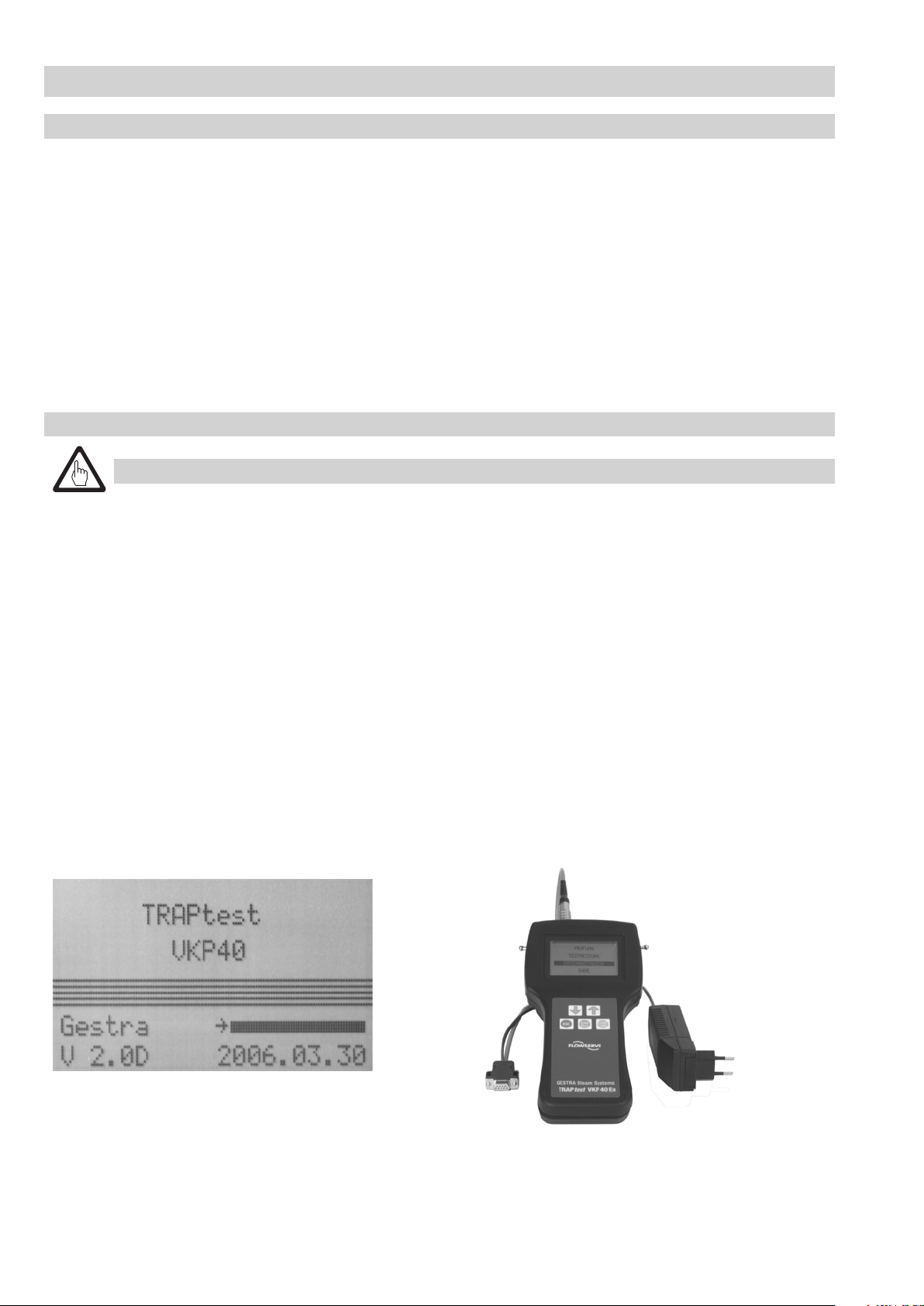
Connect the data collector VKPN 40Ex or VKPN 40 with the connecting cable VKPA 40: Insert the circular plug in the left-hand jack of
the data collector – cf. picture below – and plug the power supply unit into an earthed socket (100 – 240 V / 47 – 63 Hz).
When the data collector VKPN 40Ex / VKPN 40 is switched on, the title window of the TRAPtest program indicating the version number,
the current date and the charge level appears. During first commissioning or if the batteries are flat the date 2000.01.01 will be
shown. The date will be automatically updated during the next communication between the data collector and the PC.
The charging process is indicated on the display by an arrow to the left of the charge indicator. Once the battery is fully recharged the
charge indicator is shown as a black bar.
Pull the sleeve of the plug to unplug the device.
➞
Circular plug
Connecting cable
VKPN 40
➞
➞
Power supply
unit
➞
Adaptor for
connector
Data collector VKPN 40Ex with
connecting cable VKPA 40
Page 9

Technical Data VKP 40Ex, VKP 40 – continued –
Replacing storage batteries VKPN 40
Attention
■ Make sure that the data collector is switched off before replacing the storage battery!
■ Save data before replacing the storage battery in order to avoid loss of data.
■ Make sure that the data collector VKPN 40 is not connected via connecting cable VKPA 40 when replacing the storage
battery.
■ Incorrect charge levels are indicated after the replacement of the storage battery unit.
It takes two charging/discharging processes before the correct state of charge can be indicated.
■ Do not remove the storage battery pack as some of the acid electrolyte might escape during the process.
■ Do not throw storage batteries in water or fire (risk of explosion)!
■ Old storage batteries should not be disposed of with normal household waste – hand them in at your recycling centre.
The storage battery must be replaced when its charging capacity is no longer sufficient for the test tasks. For this purpose remove the
6 screws from the bottom of the equipment. Detach the upper part of the equipment from the lower part. Attention: The upper part is
connected to the lower part via a ribbon cable. This cable connection must not be detached. The storage battery unit is embedded with
protective elements on a green board. This unit is fixed to the bottom of the equipment by means of 4 screws. In order to exchange
the battery this whole unit has to be replaced by a genuine GESTRA AG spare part. Undo the 4 screws and remove the battery
unit. Put the new battery unit onto the two centric items of the connector. Insert two M2.5 mm screws and fasten them with 2 Nm,
then insert the other two M3 screws and fasten them with 2.5 Nm. Then mount the two halves of the equipment together, making
sure that the gasket is properly inserted and the ribbon cable is not jammed between the two equipment parts. Mount the 6
casing screws and tighten them with a torque of 0.8 Nm. The battery can now be charged as described in section “Charging storage
batteries”. Note that full capacity of a new storage battery is only obtained after about 5 complete charge and discharge cycles.
Environmental regulations have to be taken into account when disposing of storage batteries.
(See pictures in section “Replacing storage battery unit”).
Maintaining VKP 40
When used for its intended purpose the diagnostic system is maintenance-free. However, we recommend that the system should be
sent to GESTRA AG Bremen every 5 years for a general inspection.
Spare Parts
Designation Stock code
Complete storage battery unit for VKPN 40Ex / VKPN 40 (incl. 1 set of screws)
052474
Strap 052479
Holster for VKPS 40Ex 052478
Connecting cable VKPA 40 compl., incl. power supply unit 052476
Adaptor set for connector 052477
VKP 40 USB / Serial adaptor and software 052480
9
Page 10

10
Connecting and Commissioning Data Collector VKPN 40Ex, VKPN 40
Connecting data collector VKPN 40Ex or VKPN 40 to a PC
Connect the power supply unit of the connecting cable VKPA 40 with an earthed socket and insert the circular plug of the connecting
cable into the left-hand jack of the data collector VKPN 40Ex / VKPN 40.
■ If the power supply unit is not connected the data collector cannot communicate with the PC.
Connect the serial plug of the connecting cable with the PC. Use a commercially available interface connection USB-RS 232 to connect
the data collector via a USB interface to PC. Then confirm the selected interface (Com 1, Com 2, Com 3, Com 4 or Com 5) in the
TRAPtest menu EXTRAS/Interface on the PC.
■ Attention: Do not use the connecting cable VKPA 40 in explosionrisk areas!
➞
Circular plug
Connecting cable
VKPA 40
➞
Serial plug
Connecting measuring transducer VKPS 40Ex to data collector VKPN 40Ex or VPKN 40
Danger
■ Note when using the VKPN 40Ex in explosionrisk areas:
Make sure that the measuring transducer VKPS 40Ex is connected to the data collector VKPN 40Ex before you
enter an explosionrisk area. Do not open this connection in explosionrisk areas. The two connected devices
(VKPN 40Ex with VKPS 40Ex) can be in switched-on or switched-off mode when they are carried into an explosion-risk
area.
■ Do not use the data collector VKPN 40 in explosionrisk areas.
Insert the circular plug of the connecting cable VKPS 40Ex into the right-hand jack of the data collector VKPN 40Ex / VKPN 40.
To unplug the cable pull the sleeve of the connector.
➞
Data collector VKPN 40Ex with connecting cable VKPA 40
➞
Power supply
unit
➞
Adaptor for
connector
➞
Measuring transducer
VKPS 40Ex
Data collector VKPN 40Ex,
bzw. VKPN 40 with measuring transducer VKPS 40Ex
Page 11

Connecting and Commissioning Data Collector VKPN 40Ex, VKPN 40 – continued –
Commissioning data collector VKPN 40Ex or VKPN 40
■ Do not use a ball pen or any other sharp object for pressing the buttons of the data collector!
Press button START to start the data collector VKPN 40Ex / VKPN 40. The title window of the TRAPtest program appears, showing the
version number and the current date.
When the equipment is commissioned for the first time or if the battery is empty the date is indicated as 2000.01.01. During the next
communication between the data collector and the PC the date will be automatically updated.
Battery charging indicator
Date
Version
Note
■ When the date 2000.01.01 is shown the data collector can only be commissioned if the battery has been
recharged. For more information see section “Charging storage batteries” and “Fault finding list for
troubleshooting”. During the next communication between the data collector and the PC the date will be updated.
Press the ENTER key to call up the main menu::
Language Setting
Main menu of the data collector
In the menu TEST steam traps can be checked for loss of live steam – provided that data records and test tasks have been
entered previously on the PC. The recorded sound values are assessed immediately after each steam trap test by the data collector.
The test results will be saved.
In the menu TEST MEASUREMENTS steam traps can be checked for loss of live steam – without prior input of data records and
without the creation of test tasks. The recorded sound values are assessed immediately after each steam trap test by the data
collector. The test results will not be saved.
The menu DATA EXCHANGE enables communication with the PC and the organization of the data collector on the PC: test tasks are
transferred from the PC to the data collector and test results are sent from the data collector to the PC. Test tasks for the data collector
can be deleted on the PC..
■ In the menu LANGUAGE SETTING you can select the user interface language.
➔
■ Use the arrow buttons , to select (mark) the desired menu and then press the ENTER key. The current position of the cursor is
indicated by .
▲
➔
11
Page 12

12
Connecting and Commissioning Data Collector VKPN 40Ex, VKPN 40 – continued –
Switching off data collector
➔
■ Use arrow button to select (mark) the item QUIT of the main menu of the data collector and press the ENTER key. The data
collector is now switched off.
■ As long as the power supply unit is connected, the data collector cannot be switched off.
In the main menu you can press the ESC key to show the battery charge level in the title window.
For more information please refer to the Online Documentation on the PC.
Automatic deactivation
If the data collector is not operated for more than 10 minutes, it is switched off autmatically. Data stored on the data collector wil be
saved before the equipment is switched off. This process takes approx. 120 sec.
Preparing flash memory
for data storage
After switching the equipment on, the data will be loaded into the RAM memory of the data collector.
This process takes about 30 sec.
Retrieving data from
flash memory
Page 13

TRAPtest software PC program
Installing PC software
Exit all open applications on your computer.
If an older version of the TRAPtest VKP 40 software is already installed on your PC:
Save the companies that you have created in a directory of your choice. You will find the data under:
C:/Programs/Gestra/TRAPtest VKP40/Companies. Then de-install the older version of the TRAPtest software.
Please make sure that the whole program folder is deleted and, if necessary, delete any remaining directories and data.
Insert the supplied CD in your CD-ROM drive.
Upon insertion of the TRAPtest software CD the installation program starts automatically. Follow the on-screen prompts to complete the
installation.
The installation setup creates the folder GESTRA where the TRAPtest VKP 40 program will be stored. A new program icon is created on
the desktop.
Starting and quitting program
Starting the program
To start the program click the Start button, point to Programs and then click TRAPtest VKP 40 or double-click on the TRAPtest VKP 40
icon on the desktop.
Quitting the program
To quit the program click the QUIT button in the main menu of the TRAPtest program.
Deinstalling PC software
a) TRAPtest V 1.00: To de-install the program click
b) TRAPtest from V 1.10: To de-install the program click Control panel/Software.
Please make sure that the whole program folder is deleted and, if necessary, delete any remaining directories and data.
Software menus at a glance
Menu Test Objects
In the menu Test Objects all steam trap related data and the associated plant sections are entered and organized.
Menu Test Tasks
In the menu Test Tasks task lists detailing the steam traps to be tested are created and organized.
Menu Data Collector
In the menu Data Collector the communication between the PC and the data collector is established and the test tasks for the data
collector are organized.
Menu Extras
The menu Extras comprises the following submenus:
Manufacturer Import
Tester Organize company
Limit values Load update
Language Excel import
Interface Excel export
Options Clean up database
Organize steam traps Info
In the menu Manufacturer you can take down the particulars of the steam trap manufacturer whose steam traps are installed in the
plant.
In the menu Tester the names of the employees entrusted with the task of checking the steam traps are entered.
In the menu Limit Values the specified limit sound values of the different steam trap systems are indicated.
In the menu Language you can select, edit or add a language.
In the menu Interface all available ports that can be selected are shown.
In the menu Options the units [bar, °C, kg/h] or [psi, °F, lb/h] for calculating the loss can be selected.
In the menu Organize steam trap all steam trap types and names can be listed and organized. The system features a default list of all
GESTRA trap designations including the associated functional types.
In the menu Import all data records created with the predecessor version (VKP 30) can be imported.
To do so make sure that: ■ The VKP 30 software is installed on your PC
■ The company to be imported is active
Uninstall in the program folder TRAPtest VKP40.
13
Page 14

14
TRAPtest software PC program – continued –
Software menus at a glance – continued –
In the menu Organize company the designation of the respective database (e. g. the name of the company, department, section or
building) is entered here.
Attention
■ When a designation is deleted the whole database created under this designation will be deleted!
The menu Load update enables the installation of software updates for the data collector VKPN 40Ex / VKPN 40.
Attention
■ Note that there is no confirmation request. The old operating system and all data that may still be stored on
the data collector will be deleted!
In the menu Excel Import you can import data from the program MS Excel.
In the menu Excel Export you can export data from the TRAPtest VKP 40 program to an Excel table (from Excel 97).
In the menu Clean up database the TRAPtest VKP 40 program compresses the database.
The menu Info gives information on the manufacturer, version number of the installed software and the currently selected database
designation (name of the company).
The Import/Export function allows the import of databases (companies) created with other PCs and the export of databases (companies)
to other PCs.
Menu Financial Analysis
Provided that the specific steam costs and annual operating hours have been entered in the system, the annual loss caused by faulty
steam traps can be calculated and analysed in this menu. The estimated steam loss caused by defective traps is based on empirically
ascertained reference values.
Online Documentation
The Online Documentation offers a detailed description of the functions of the diagnostic system. It is available in GERMAN and
ENGLISH. Should you require a translation in your language please contact the manufacturer or its subsidiary or agency in your country.
Page 15

Data Exchange between PC and Data Collector VKPN 40Ex or VKPN 40
Attention
■ If the power supply unit is not connected the data collector cannot communicate with the PC.
The menu Data Collector enables the communication between the data collector and the PC and the organization of the data collector
via PC. For more information refer to section “Transferring test tasks to data collector”, “Deleting test tasks for data collector” and
“Transferring test results from data collector to PC” in the Online Documentation of the PC program.
Make sure that the data collector is connected and ready for use and then select the submenu “Data exchange” of the main menu of
the data collector (“Connecting and Commissioning” see pages 10 – 12).
When selecting the menu “Data exchange” the following display appears:
During the data transfer the following display appears:
No. of the test task that is being
transferred
During a data exchange information on the transferred data is also indicated:
“Tasks to VKPN” (if test tasks are transferred to the data collector) or
“Delete task” (if test tasks are deleted on the data collector).
Note
■ A safety protocol is created in order to prevent any loss of data during the transfer.
Consequently, the transfer rate can vary between 30 seconds and 1.5 minutes for 100 steam traps.
Number of test objects still
to be transferred
Total number of all test objects
for the test task in process
Once the data transfer is completed the display “Waiting for data” appears.
Press the ENTER key to return to the main menu of the data collector.
15
Page 16

16
Checking Steam Traps
Test
In the menu TEST steam traps can be checked for loss of live steam – provided that data records and test tasks have been entered
previously on the PC. The test results will be saved.
Note
■ During a test the measuring transducer VKPS 40Ex also measures the surface temperature of the steam trap. If the
service pressure prevailing at the place of installation has been specificied, the diagnostic system will be able to
identify the steam trap that causes the banking-up of condensate by comparing the boiling temperature associated
with the service pressure and the temperature measured at the steam trap.
(For more information see Online Documentation / Menu Test Objects / Creating Test Objects).
Attention
■ For a correct temperature measurement it is important that the surface of the reference point on the trap
where the tip of the measuring probe is applied is smooth and metallically bare. Otherwise considerable
deviations between the temperature reading and the actual temperature will be the consequence, resulting in
faulty analysis and incorrect evaluation.
Connect the measuring transducer VKPS 40Ex with the data collector (“Connecting and commissioning” see pages 10 – 12).
When the data collector is ready for operation select the submenu Test.
The display will show the test tasks transferred from the PC to the data collector as well as their counting numbers, the associated plant
designation and the designation of the plant section.
Serial no. of test task
➔
Use the arrow buttons , to mark the test task in question and press the ENTER key. The cursor position is indicated by .
To scroll the contents of a window keep the arrow button ( or ) pressed down.
The display shows the task number, the plant designation and the designation of the plant section as well as the task list of the
steam traps to be checked (test objects) and the individual traps with their places of installation.
➔
➔
➔
Designation of plant
Designation of plant section
▲
Page 17

Checking Steam Traps – continued –
Test – continued –
Use the arrow buttons , to mark the steam trap to be tested and press the ENTER key. The cursor position is indicated by .
To scroll the contents of a window keep the arrow button ( or ) pressed down.
The limit sound value (LV) and the threshold value (TV) are displayed as horizontal lines in the graphical representation of
the sound level.
Note
■ As soon as the graphical representation is displayed by the data collector, the measuring transducer will be
automatically switched off. (The LED of the measuring transducer lights up when the test starts).
Attention
■ The connection between the data collector and the measuring transducer must not be undone during this
operating condition.
■ The storage batteries of the data collector supply the measuring transducer with power. Avoid long
interruptions between selecting the steam trap for testing (graphical representation on the display) and the
test start so that the battery can hold charge for a longer period of time.
➔
➔
➔
Limit value (LV)
➔
▲
Sound intensity
Threshold value (TV)
If the selected steam trap cannot or should not be checked for reasons given in the following list of comments, call up this list by using
the arrow buttons or .
➔
➔
➔
Use the arrow buttons , to select (mark) the respective comment of the list and press the ENTER key.
By pressing the ENTER key the comment will be saved and the task list with the cursor positioned beside the next steam trap to be
tested appears. To test the selected steam trap, put the tip of the measuring transducer probe VKPS 40Ex vertically onto the surface
of the trap body on the specified reference point (see section “Reference point for measurement”). The test starts once the measuring
transducer is pressed down to the stop. The LED of the measuring transducer lights up and the display of the data collector shows the
text “Test running”.
During the test the recorded readings are shown as a graph.
➔
17
Page 18

18
Checking Steam Traps – continued –
Test – continued –
If the sound level reaches or falls below the threshold value of the sound level during a test before 10 seconds have elapsed, the test
will be automatically finished after 10 seconds. Otherwise the test takes 20 seconds.
After the test the test result will be shown:
Test result
Possible evaluations:
OK: Yes Trap works without steam loss
OK: No Trap defective
OK: BC Banking-up of condensate possible (only if the service pressure has been specified on the PC)
OK: FN Trap influenced by foreign noise (see section “Foreign noise”)
For more information refer to section “Evaluation criteria” and “Evaluating steam traps” in the Online Documentation.
➔
If you want to repeat the test, use the down arrow button and then press the ENTER key. (The display shows again the graphical
respresentation with the limit and threshold sound values LV and TV in the form of horizontal lines).
To save the test result press the ENTER key.
After saving the test results the task list appears. Checked steam traps are ticked off ✓.
The next steam trap to be tested is marked in the list with the symbol .
▲
Page 19

Checking Steam Traps – continued –
Test measurement
In the menu TEST MEASUREMENT steam traps can be checked for loss of live steam – without prior input of data records and
without the creation of test tasks. The test results will not be saved.
When the data collector is ready for operation select the submenu TEST MEASUREMENT
(“Connecting and Commissioning” see pages 10 – 12).
The display shows the list LOCATION.
Use the arrow buttons , to select (mark) the place of installation of the steam trap and then press the
ENTER key.
The display shows the list TYPE.
➔
➔
➔
Use the arrow buttons , to select (mark) the functional type of the steam trap used and then press the
ENTER key.
The display shows the following graphic:
➔
For the rest of the steam trap test proceed as described in section TEST.
Note that the test results will not be saved.
19
Page 20

20
Checking Steam Traps – continued –
Foreign noise
If sound levels (mean values) exceed the specified limits, the display shows the screen Foreign Noise Test.
For more information refer to section “Evaluation criteria” and “Evaluating steam traps” of the
Online Documentation.
Measured value sensed at trap
Up-to-the-minute reading during
foreign noise test
Press the tip of the measuring probe at various points in the close vicinity of the steam trap (supports, uninsulated pipes upstream and
downstream of the trap) to detect the respective sound levels.
By comparing the MEAN VALUE with the MEASURED VALUE the influence of foreign noise on the test can be confirmed or ruled out.
If the detected sound level is below the mean value of the trap test (MEASURED VALUE < MEAN VALUE), an influence of foreign noise
can be ruled out.
In this case use the arrow buttons , to mark FOREIGN NOISE: NO.
➔
➔
If the detected sound level exceeds the mean value of the trap test (MEASURED VALUE > MEAN VALUE), the place where the steam
trap is installed is influenced by foreign noise. In this case use the arrow buttons , to mark FOREIGN NOISE: YES.
Press the ENTER key to show the recorded sound curve and its evaluation on the display.
OK: No Trap defective
or
OK: FN Trap influenced by foreign noise
Press the ENTER key to save the result.
Reference points for measurement
■ Make sure that the measuring probe is applied to the same points on the trap bodies of steam traps of the same type so
that the test results of the steam traps can be compared and changes can be ascertained when repeating the tests.
■ Provided that the upstream pressure has been specified on the PC, the temperature of the steam trap body will also
be measured and used for the analysis. In this case the surface of the reference point on the trap where the tip of the
measuring probe is applied has to be smooth and metallically bare. Otherwise considerable deviations between the
temperature reading and the actual temperature will be the consequence, resulting in faulty analysis and incorrect
evaluation.
Note that the probe shall be applied at right angles to the trap surface.
➔
➔
Page 21

Checking Steam Traps – continued –
Reference points for measurement – continued –
The reference point of thermostatic bimetallic and membrane steam traps is located on the cover between the cover and the cover
flange or at the side of the cover.
Example: Bimetallic steam trap type BK 45
Example: Membrane steam trap type MK 45
Example: Bimetallic steam trap type BK 15
The reference point of float traps is located on the highest point on the cover or at the side of the cover.
Example: Float trap type UNA 2
Example: Float trap type UNA 1
21
Page 22

22
Fault finding list for troubleshooting
Data collector VKPN 40Ex, VKPN 40
Fault: No indication on the display (power supply unit not connected).
Possible cause: Storage batteries are empty.
Remedy: Connect the data collector with the connecting cable VKPA 40, plug the power supply unit into an earthed
socket and recharge the battery for at least 4 hours (see section “Charging storage batteries”).
Fault: No indication on the display (connecting cable VKP 40A connected, power supply unit plugged in earthed
socket).
Possible cause: Storage batteries are defective.
Remedy: Replace the battery unit (see section “Replacing battery unit”).
Fault: Date indicated 2000.01.01.
Possible cause: If the storage battery voltage is below 2.5 V the protective circuit-breaker switches off the battery.
The date is set to 2000.01.01.
Remedy: Connect the data collector with the connecting cable VKPA 40, plug the power supply unit into an earthed
socket and recharge the battery for at least 4 hours (see section “Charging storage batteries”).
Measuring transducer VKPS 40Ex
Fault: LED not illuminated.
Possible cause: The LED lights up only when the measuring transducer is switched on by the data collector.
Remedy: When the graphic appears on the display of the data collector, the measuring transducer will be switched on.
(See section “Checking Steam Traps”). The LED lights up only when the measuring transducer is pressed
down to the stop onto the trap body.
Fault: LED not illuminated although the display of the data collector shows the graphic and the test
has been started.
Possible cause: LED defective.
Remedy: Please send the measuring transducer to GESTRA AG for repair.
Screen display on PC
Fault: The text on the buttons is incomplete.
Possible cause: The screen resolution setting is probably unsuitable.
Remedy: Choose a suitable screen resolution setting.
Fault: There are numbers (instead of text) on the buttons.
Possible cause: The terms listed in the language table may have been deleted (menu Extras /Language).
Remedy: Enter the missing term in the menu Extras/Language.
Data transfer
error code no.
0 VKPN 40 not connected or not ready for operation Data collector not connected or not in menu “Data transfer”
3 Timeout during data reception Repeat transfer
5 VKPN 40 aborted by user Repeat transfer
10
11 No tasks available for VKPN 40 Send test tasks and repeat transfer
13
15
17
19
PC message Cause / troubleshooting
Storage capacity of VKPN 40 not sufficient Delete test tasks on VKPN 40 and repeat transfer
Task already stored on VKPN 40 Delete test task and repeat transfer
Wrong command Repeat transfer
Program memory could not be deleted Repeat transfer
Signal transmission time delay VKPN 40
1. VKP 40 not in menu “Data transfer”
2. Incorrect setting in Extras / Interface
Page 23

EC Type Approval
23
Page 24

Agencies all over the world:
www.gestra.de
España
GESTRA ESPAÑOLA S.A.
Luis Cabrera, 86-88
E-28002 Madrid
Tel. 00 34 91 / 51 52 032
Fax 00 34 91 / 41 36 747; 5 15 20 36
E-mail: aromero@flowserve.com
Great Britain
Flowserve Flow Control (UK) Ltd.
Burrel Road, Haywards Heath
West Sussex RH 16 1TL
Tel. 00 44 14 44 / 31 44 00
Fax 00 44 14 44 / 31 45 57
E-mail: gestraukinfo@flowserve.com
Italia
Polska
GESTRA POLONIA Spolka z.o.o.
Ul. Schuberta 104
PL - 80-172 Gdansk
Tel. 00 48 58 / 3 06 10 -02 od 10
Fax 00 48 58 / 3 06 33 00
E-mail: gestra@gestra.pl
Portugal
Flowserve Portuguesa, Lda.
Av. Dr. Antunes Guimarães, 1159
Porto 4100-082
Tel. 0 03 51 22 / 6 19 87 70
Fax 0 03 5122 / 6 10 75 75
E-mail: jtavares@flowserve.com
USA
Flowserve S.p.A.
Flow Control Division
Via Prealpi, 30
l-20032 Cormano (MI)
Tel. 00 39 02 / 66 32 51
Fax 00 39 02 / 66 32 55 60
E-mail: infoitaly@flowserve.com
GESTRA AG
Postfach 10 54 60, D-28054 Bremen
Münchener Str. 77, D-28215 Bremen
Telefon +49 (0) 421 35 03 -0
Telefax +49 (0) 421 35 03 -393
E-Mail gestra.ag@flowserve.com
Internet www.gestra.de
818535-01/506c · © 2005 GESTRA AG · Bremen · Printed in Germany
24
Flowserve GESTRA U.S.
2341 Ampere Drive
Louisville, KY 40299
Tel.: 00 15 02 / 502 267 2205
Fax: 00 15 02 / 502 266 5397
E-mail: dgoodwin@flowserve.com
 Loading...