

Page 1
USER INSTRUCTIONS
Valtek Control Products
Spring Cylinder Linear Actuators
FCD VLENIM0002-00-AQ - 10/14 (Replaces VLAIM002)
Installation
Operation
Maintenance
Experience In Motion
Page 2
Valtek Spring Cylinder Linear Actuators FCD VLENIM002-00-AQ 10/14
GENERAL INFORMATION
The following instructions are designed to assist in installing,
troubleshooting and servicing Valtek spring cylinder actuators. Product
users and maintenance personnel should thoroughly review this
bulletin prior to installing, operating or disassembling the actuator.
Separate installation, operation and maintenance instructions cover
additional features (such as hand-wheels, limit stops, fail-safe systems
or limit switches).
This publication does not contain information on Flowserve positioners.
Refer to the appropriate installation operation and maintenance
instructions for installing, maintaining, troubleshooting, calibrating and
operating Flowserve positioners.
To avoid possible injury to personnel or dam-age to valve parts,
WARNING and CAUTION notes must be strictly followed. Modifying
this product, substituting non-factory or inferior parts or using
maintenance procedures other than outlined could drastically affect
performance, void product warranties and be hazardous to personnel
and equipment.
WARNING: Standard industry safety practices must be
a
followed when working on this or any process control product.
Specifically, personal protection and lifting devices must be
used as warranted.
NOTE: If the actuator is attached to a valve body assembly,
see Installation, Operation, Maintenance Instructions 1 for
overhead clearances.
Table 1: Overhead Clearance for Disassembly
Actuator Size Minimum Clearance
25 6 inches
50 8 inches
100,200,300 400,500,600 9 inches
1. Connect the air supply and instrument signal air lines to the two
appropriately marked connections on the positioner. Since both
the cylinder and positioner are suitable for 150 psi air supply, an air
regulator should not be used unless the supply exceeds 150 psi.
NOTE: In some cases, air supply must be limited to 100 psi
rather than 150 psi; this will be indicated by a sticker found
near the upper air port on the cylinder.
WARNING: To avoid personal injury or equipment damage, do
a
not exceed recommended supply pressure.
2. Installation of an air filter on the supply line is recommended.
3. Use a soap solution to make sure all air connections are leak free.
MAINTENANCE
Unpacking
While unpacking the actuator, check packing list against materials
received. Lists describing the actuator and accessories are included in
each shipping container.
1. Position the lifting straps and hoist to avoid damage to the tubing
and mounted accessories when lifting the actuator from the
shipping container.
WARNING: When lifting an actuator with lifting straps through
a
the yoke legs, be aware the center of gravity may be above the
lifting point. Therefore, support must be given to prevent the
actuator from rotating or causing serious injury to personnel or
damage to nearby equipment.
2. Contact your shipper immediately in the event of shipping damage.
3. Contact your Flowserve representative for any problems.
Installation
2
Prior to installation, make sure adequate overhead clearance for the
actuator is provided to allow for proper removal from the valve body
and for proper maintenance. Refer to Table 1.
At least once every six months, check for proper operation by following
the preventative maintenance steps outlined below. These steps can be
performed while the actuator is in service and, in some cases, without
interrupting service. If an internal problem is suspected with the actuator, refer to the “Disassembly and Reassembly” section.
1. Examine the actuator for damage caused by corrosive fumes and
process drippings.
2. Clean the actuator and repaint any areas of severe oxidation.
3. If possible, stroke the actuator and check for smooth, full-stroke
operation.
WARNING: To avoid serious injury, keep hands, hair and
a
clothing away from all moving parts while operating the
actuator.
4. Make sure positioner mounting bolts, linkage and stem clamp are
securely fastened.
5. Ensure all accessories, brackets and associated bolting are securely
fastened.
6. If possible, remove air supply and observe actuator for correct
fail-safe action.
7. Check rubber bellows for wear.
Page 3

Valtek Spring Cylinder Linear Actuators FCD VLENIM002-00-AQ 10/14
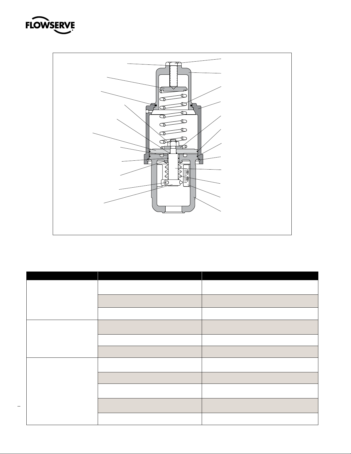
Adjusting Screw Gasket
(Item No. 248 )
Spring Button
(Item No. 227 )
Actuator Stem Locknut
(Item No. 348 )
Piston Stem O-ring
(Item No. 272 )
Piston
(Item No. 225 )
Upper Stem Bushing
(Item No. 253 )
Actuator Stem O-ring
(Item No. 275 )
Lower Stem Bushing
(Item No. 254 )
Stem Clamp Bolting
(Item No. 240/345 )
Stem Clamp
(Item No. 249 )
O
S
Adjusting Screw
(Item No. 210)
Cylinder
(Item No. 202)
Spring
(Item No. 229)
Stem Spacer
(Item No. 223)
Piston O-ring
(Item No. 271)
Yoke O-ring
(Item No. 274)
Cylinder Retaining
Ring
(Item No. 256)
Actuator Stem
(Item No. 211)
Stem Bellows
(Item No. 247)
Stroke Plate
(Item No. 213)
Yoke
(Item No. 201)
Figure 1: Air-to-retract Cylinder Actuator
NOTE: Item numbers correspond directly to actuator’s bill of material. Refer to it for specific part numbers
8. Spray soap solution around the cylinder retaining ring, the adjusting
screw and the lower actuator stem bushing to check for air leaks
through the O-rings and gasket.
9. Clean any dirt or foreign material from the actuator stem.
10. If an air filter is supplied, check and replace cartridge as necessary.
DISASSEMBLY AND REASSEMBLY
Disassembling the Actuator
Refer to Figures 1 through 5 to disassemble the cylinder actuator.
1. Shut off air supply. If the actuator is installed on a Valtek valve,
remove the actuator per Installation Operation and Maintenance
Instructions 1. If installed on other valves, remove the yoke to
bonnet connections, loosen stem clamp bolt and turn actuator
off of plug stem threads.
WARNING: To avoid serious injury, depressurize the line to
a
atmospheric pressure and drain all fluids before working on
the actuator.
2. Disconnect all tubing. Remove stem clamp and stem bellows from
the actuator stem.
3. Relieve spring compression completely by removing the adjusting
screw. Remove adjusting screw gasket from adjusting screw.
CAUTION: Do not use a screwdriver or bar to turn the adjusting
a
screw; instead, use a wrench on the flats of the screw.
WARNING: To avoid serious personal injury, relieve the spring
a
compression before further disassembly. The cylinder could
possibly fly off the yoke when removing the cylinder retaining
ring.
4. Remove the cylinder retaining ring from the groove at the base of
the cylinder by using two screw¬drivers. Insert one screwdriver
in slot found in the ring and pry the ring from the groove. Use the
other screwdriver to help work the ring out of the cylinder groove.
5. Pull the cylinder off the yoke and piston; some O-ring resistance
may be felt.
WARNING: To avoid serious personal injury, do not use air
a
pressure to remove the cylinder. The cylinder could possibly fly
off the yoke.
6. For heavy-duty spring designs using a spring cap (see Figure 4),
remove the spring cap and cap O-ring from the cylinder.
7. For air-to-extend configurations, slowly loosen and remove the
actuator stem locknut. Be certain the piston follows the stem
locknut up the actuator stem and does not bind on the actuator
stem. Remove the actuator stem
3
flowserve.com
Page 4

Valtek Spring Cylinder Linear Actuators FCD VLENIM002-00-AQ 10/14
Adjusting Screw Gasket
(Item No. 248)
Cylinder
(Item No. 202)
Spring Button
(Item No. 227)
Piston O-ring
(Item No. 271)
Piston Stem O-ring
(Item No. 272)
Spring
(Item No. 229)
Upper Stem Bushing
(Item No. 253)
Lower Stem Bushing
(Item No. 254)
Stem Clamp Bolting
(Item No. 240/345)
Stem Clamp
(Item No. 249)
O
S
Adjusting Screw
(Item No. 210)
Actuator Stem Locknut
(Item No. 348)
Piston
(Item No. 225)
Stem Spacer
(Item No. 228)
Actuator Stem O-ring
(Item No. 275)
Yoke O-ring
(Item No. 274)
Cylinder Retaining Ring
(Item No. 256)
Actuator Stem
(Item No. 211)
Stem Bellows
(Item No. 247)
Stroke Plate
(Item No. 213)
Yoke
(Item No. 201)
Figure 2: Air-to-extend Cylinder Actuator
NOTE: item numbers correspond directly to actuator’s bill of material. Refer to it for specific part numbers.
NOTE: The dual, heavy-duty spring configuration (Figure 3) has
two springs, one inside the other. Remove both springs during
this step.
8. Remove the piston O-ring, piston stem O-ring and yoke O-ring.
9. Remove the actuator stem O-ring.
NOTE: The upper and lower stem bushings are pressed into
the yoke Removal of the bushings to replace the actuator stem
O-ring is unnecessary.
10. Use appropriately sized press to push worn or damaged bushings
out of yoke.
Reassembling the Actuator
To reassemble the cylinder actuator, refer to Figures 1 through 5:
1. All O-rings should be replaced. New O-rings should be lubricated
with a silicone lubricant (Dow Corning 55M or equivalent).
Silicone O-rings must be lubricated with Magnalube-G lubricant
or equivalent. Do not use silicone lubricant on silicone O-rings.
2. Thoroughly clean all internal parts before beginning assembly.
Lubricate cylinder wall with silicone lubricant.
4
3. Lubricate the outside of the replacement bushings if the stem
bushings have been removed. Press a new lower stem bushing
into the actuator stem bore in the yoke until it bottoms out. Press
the upper stem bushing into the bore until it is flush with the top
of the yoke (refer to Figures 1 or 2).
4. Replace the actuator stem O-ring and yoke O-ring.
5. Reassemble the piston, piston stem O-ring and stem spacer on
the actuator stem according to the proper air-action (refer to
either Figure 1 or 2). Replace the piston O-ring. Air-to-extend
configurations require the spring button to be stored under
actuator stem locknut. Tighten the locknut firmly.
NOTE: When reassembling heavy-duty, spring design actua-
tors, the spring guide must be first inserted under the actuator
stem locknut (see Figures 3 and 4).
6. For air-to-extend configurations, place the spring under the piston
and insert the actuator stem through the yoke, being careful not to
pinch the actuator stem O-ring or gall the stem and stem bushings.
For air-to-retract configurations, insert the actuator stem through
the yoke and place the spring(s) and spring button above the
piston.
7. Replace the cap O-ring and install the spring cap in the cylinder
when using heavy-duty spring designs using spring caps
(see Figure 4).
8. Install the cylinder, making sure the yoke is pushed deeply enough
into the cylinder to allow the cylinder retaining ring to be installed.
Care should be taken not to scar or cut the piston and yoke
O-rings.
Page 5

Valtek Spring Cylinder Linear Actuators FCD VLENIM002-00-AQ 10/14
Adjusting Screw Gasket
(Item No. 248 )
Outer Spring
(Item No. 229 )
Inner Spring
(Item No. 230)
Actuator Stem Locknut
(Item No. 348 )
Piston Stem O-ring
(Item No. 272 )
Piston
(Item No. 225 )
Upper Stem Bushing
(Item No. 253 )
Actuator Stem O-ring
(Item No. 275 )
Lower Stem Bushing
(Item No. 254 )
Stem Clamp Bolting
(Item No. 240/345 )
Stem Clamp
(Item No. 249 )
O
S
Adjusting Screw
(Item No. 210)
Cylinder
(Item No. 202)
Spring Button
(Item No. 227)
Spring Guide
(Item No. 326)
Piston O-ring
(Item No. 271)
Yoke O-ring
(Item No. 274)
Cylinder Retaining Ring
(Item No. 256)
Actuator Stem
(Item No. 211)
Stem Bellows
(Item No. 247)
Stroke Plate
(Item No. 213)
Yoke
(Item No. 201)
Figure 3: Dual-spring Cylinder Actuator
NOTE: Item numbers correspond directly to actuator’s bill of material. Refer to it for specific part numbers.
9. Re-insert the cylinder retaining ring by until it snaps in place. Use
a hammer and drift punch to lightly tap the retaining ring in the
groove.
WARNING: To avoid personal injury, the cylinder retaining ring
a
must be solidly in place. The cylinder could possibly fly off
when pressurized. Be careful not to pinch or cut fingers on the
square edges of the retaining ring during installation.
10. Reinstall the adjusting screw using a new adjusting screw gasket.
NOTE: Be certain the hole in the spring button is directly
centered under the adjusting screw hole in the cylinder on
air-to-retract configurations.
11. Tighten the adjusting screw enough to provide an air seal with the
gasket. Do not over tighten.
12. Reinstall the stem bellows and stem clamp.
NOTE: To ensure maximum clamping strength when installing
the stem clamp, make sure the stem clamp bolting is perpendicular to one of the slots machined into the actuator stem. 13.
Apply air over the piston. Tighten the stem clamp bolting with
the stem clamp adjusted to point at the closed position of the
stroke indicator plate.
NOTE: If the actuator is installed on a Flowserve valve, refer to
Installation, Operation, Maintenance Instructions 1 for correct
plug stem thread engagement.
14. Reconnect tubing, supply and signal lines.
Reversing the Air-action
To change the air action from air-to-retract to air-to extend, or vice
versa, refer to Figures 1, 2 or 5:
NOTE: Heavy-duty spring actuators are not reversible.
1. Disassemble the actuator according to the “Disassembling the
Actuator” section.
2. For air-to-retract action, reassemble the actuator with stem spacer
and spring button over the piston.
3. For air-to-extend action, reassemble with spring and stem spacer
below the piston and with the spring button stored above the
piston.
4. Reassemble the actuator according to the “Reassembling the
Actuator” section.
5. The positioner must also be reversed. See the appropriate
positioner maintenance instructions.
5
flowserve.com
Page 6
Valtek Spring Cylinder Linear Actuators FCD VLENIM002-00-AQ 10/14
Adjusting Screw
Adjusting Screw Gasket
(Item No. 248 )
Spring Button
(Item No. 227 )
Cap O-ring
(Item No. 270 )
Actuator Stem Locknut
(Item No. 348 )
Piston Stem O-ring
(Item No. 272 )
Piston
(Item No. 225 )
Upper Stem Bushing
(Item No. 253 )
Actuator Stem O-ring
(Item No. 275 )
Lower Stem Bushing
(Item No. 254 )
Stem Clamp Bolting
(Item No. 240/345 )
Stem Clamp
(Item No. 249 )
O
S
Figure 4: Cap-spring Cylinder Actuator
NOTE: Item numbers correspond directly to actuator’s bill of material. Refer to it for specific part numbers.
(Item No. 210)
Spring Cap
(Item No. 325)
Spring
(Item No. 229)
Cylinder
(Item No. 202)
Spring Guide
(Item No. 326)
Piston O-ring
(Item No. 271)
Yoke O-ring
(Item No. 274)
Cylinder Retaining Ring
(Item No. 256)
Actuator Stem
(Item No. 211)
Stem Bellows
(Item No. 247)
Stroke Plate
(Item No. 213)
Yoke
(Item No. 201)
Troubleshooting
Problem Probable Cause Corrective Action
High air consumption or leakage
Actuator does not move to fail
position upon loss of air supply
pressure
Jerky or sticking stem travel
6
Leaks in the air supply or instrument signal
Tighten connections and replace any leaking lines
system
Malfunctioning positioner Refer to appropriate positioner maintenance bulletin
Leaks through O-rings or adjusting screw gasket Replace O-rings or gasket
Air pressure in cylinder not venting because of
Refer to appropriate positioner maintenance bulletin
faulty positioner
Spring failure Replace spring
Internal valve problem Refer to valve’s maintenance bulletin
Insufficient air supply pressure Check air supply and any filters or regulators; check for
leaking O-rings
Unlubricated cylinder wall Lubricate cylinder wall with silicone lubricant
Worn or damaged stem bushings Check actuator stem for damage; replace actuator stem,
O-ring, and stem bushings, if necessary
Improperly assembled spring Disassemble actuator and check cylinder and piston for
damage; reassemble actuator correctly
Internal valve problem Refer to valve’s maintenance instructions
Page 7
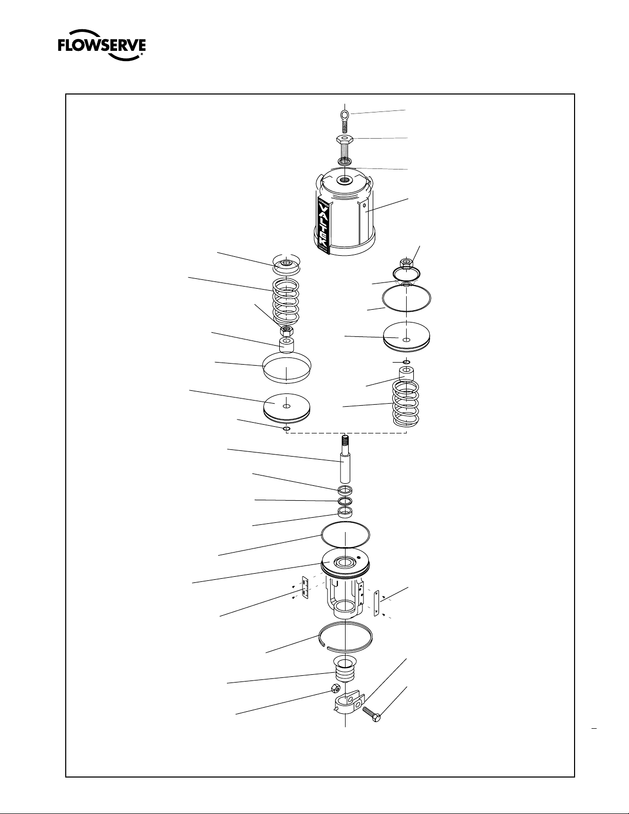
Spring Button
(Item No. 227 )
Spring
(Item No. 229 )
Actuator Stem Lock Nut
(Item No. 348)
Stem Spacer
(Item No. 228 )
Piston O-ring
(Item No. 271 )
Piston
(Item No. 225 )
Piston Stem O-ring
(Item No. 272 )
Valtek Spring Cylinder Linear Actuators FCD VLENIM002-00-AQ 10/14
Lifting Ring
(Item No. 209 )
Adjusting Scre w
(Item No. 210 )
Adjusting Screw Gasket
(Item No. 248)
Cylinder
(Item No. 202 )
Actuator Stem Lock Nut
(Item No. 348)
Spring Button
(Item No. 227 )
Piston O-ring
(Item No. 271 )
Piston
(Item No. 225 )
Piston Stem O-ring
(Item No. 272 )
Stem Spacer
Spring
(Item No. 229 )
Actuator Stem
(Item No. 211 )
Upper Stem Bushin g
(Item No. 253 )
Actuator Stem O-ring
(Item No. 275 )
Lower Stem Bushin g
(Item No. 254 )
Yoke O-ring
(Item No. 274 )
Yoke
(Item No. 201 )
Stroke Plate
(Item No. 213 )
Cylinder Retaining Rin g
(Item No. 256 )
Stem Bellows
(Item No. 247)
Stem Clamp Nut
(Item No. 345)
Serial Plate
(Item No. 252 )
Stem Clamp
(Item No. 249)
Stem Clamp Bol t
(Item No. 240)
E0170
7
Figure 5: Exploded View, Spring Cylinder Actuator
NOTE: Item numbers correspond directly to actuator’s bill of material. Refer to it for specific part numbers.
flowserve.com
Page 8

FCD VLENIM0002-00-AQ Printed in USA. November 2014
To find your local Flowserve representative
or for more information about Flowserve Corporation, visit
www.flowserve.com.
USA
Flowserve Flow Control Division
1350 N. Mt. Springs Parkway
Springville, UT 84663
USA
Phone: +1 801 489 8611
Fax: +1 801 489 3719
Austria
Flowserve Control Valves GmbH
Kasernengasse 6
9500 Villach
Austria
Phone: 43 (0) 4242 41 181 0
Fax: 43 (0) 4242 41181 50
France
Flowserve France S.A.S.
BP 60 63307 Thiers Cedex
France
Phone: 33 4738 04266
Fax: 33 4738 01424
India
Flowserve India Controls Pvt Ltd.
Plot # 4, 1A, Road #8 EPIP
Whitefield
Bangalore, Karnataka, 560066
India
Phone: 91 80 40146200
Fax: 91 80 28410286
Flowserve Corporation has established industry leadership in the design and manufacture of its products. When properly selected, this Flowserve product is designed to perform its intended
function safely during its useful life. However, the purchaser or user of Flowserve products should be aware that Flowserve products might be used in numerous applications under a wide
variety of industrial service conditions. Although Flowserve can (and often does) provide general guidelines, it cannot provide specific data and warnings for all possible applications. The purchaser/user must therefore assume the ultimate responsibility for the proper sizing and selection, installation, operation, and maintenance of Flowserve products. The purchaser/user should
read and understand the Installation Operation Maintenance (IOM) instructions included with the product, and train its employees and contractors in the safe use of Flowserve products in
connection with the specific application.
While the information and specifications contained in this literature are believed to be accurate, they are supplied for informative purposes only and should not be considered certified or as
a guarantee of satisfactory results by reliance thereon. Nothing contained herein is to be construed as a warranty or guarantee, express or implied, regarding any matter with respect to this
product. Because Flowserve is continually improving and upgrading its product design, the specifications, dimensions and information contained herein are subject to change without notice.
Should any question arise concerning these provisions, the purchaser/user should contact Flowserve Corporation at any one of its worldwide operations or offices.
© 2014 Flowserve Corporation, Irving, Texas, USA. Flowserve is a registered trademark of Flowserve Corporation.
China
Flowserve Fluid Motion and
Control (Suzhou) Co., Ltd.
No. 35, Baiyu Road
Suzhou Industrial Park, Suzhou
Jiangsu Province, P.R. 215021
China
Phone: 86 512 6288 8790
Fax: 86 512 6288 8736
Singapore
Flowserve Pte. Ltd.
12 Tuas Avenue 20
Republic of Singapore 638824
Phone: 65 6879 8900
Fax: 65 6862 4940
Saudi Arabia
Flowserve Abahsain Flow Control
Co., Ltd.
Makkah Road, Phase 4
Plot 10 & 12, 2nd Industrial City
Damman, Kingdom of Saudi
Arabia
Phone: +966 3 857 3150 ext. 243
Fax: +966 3 857 4243
flowserve.com
 Loading...