

Page 1

Valtek StarPac Intelligent
Control Systems
GENERAL INFORMATION
The following instructions are designed to assist in
unpacking, installing and performing maintenance as
required on Valtek® StarPac® Intelligent Control Systems. Product users and maintenance personnel should
thoroughly review this bulletin prior to installing, operating, or performing any maintenance on the valve.
More detailed installation, maintenance and operation instructions are included in the StarPac manual;
refer to it when more information is needed.
Separate Flowserve Installation, Operation and Maintenance (IOM) manuals cover the valve (IOM 1 or IOM
27), actuator (IOM 2 or IOM 31) and positioner (IOM 45)
portions of the system and other accessories. Refer to
the appropriate instructions when this information is
needed.
To avoid possible injury to personnel or dam-
age to valve parts, WARNING and CAUTION
notes must be strictly adhered to. Modifying
this product, substituting non-factory parts, or
inferior parts, or using maintenance procedures
other than outlined could drastically affect performance and be hazardous to personnel and
equipment, and may void existing warranties.
WARNING: Standard industry safety practices
must be adhered to when working on this, or any
other, process control product. Specifically,
personal protective and lifting devices must be
used as warranted.
Unpacking
1. While unpacking the StarPac system, check the
packing list against the materials received. Lists
describing the system and accessories are included in each shipping container.
2. When lifting the system from the shipping container, position lifting straps to avoid damage to
tubing and mounted accessories. Valves up through
6-inches may be lifted by the actuator lifting ring.
On larger systems, lift unit using lifting straps or
hooks through the yoke legs and outer end of body.
WARNING: When lifting a valve/actuator assembly with lifting straps, be aware the center
of gravity may be above the lifting point. Therefore, support must be given to prevent the
valve/actuator from rotating. Failure to do so
can cause serious injury to personnel or damage to nearby equipment.
3. In the event of shipping damage, contact the shipper immediately.
4. Should any problem arise, contact a Flowserve
representative.
INSTALLATION
Valve Installation
The StarPac Intelligent Control System valve is installed in the same manner as a conventional control
valve and according to industry standards. Refer to the
appropriate valve installation, operation, maintenance
instructions for proper installation procedures.
If the StarPac system is being installed in an insulated
process line, do not place more than four inches of
insulation around the StarPac pressure or temperature
sensors; otherwise the sensors may not operate
properly. In addition, NEVER insulate the StarPac
electronics assembly or remote-mounted temperature/
pressure sensors (when used).
CAUTION: Do not insulate the StarPac electronics
housing or remote-mounted pressure or temperature sensors; otherwise excessive heat may build
up and affect operation.
41-1Valtek No. 125694
Page 2
Valtek StarPac
Valtek StarPac
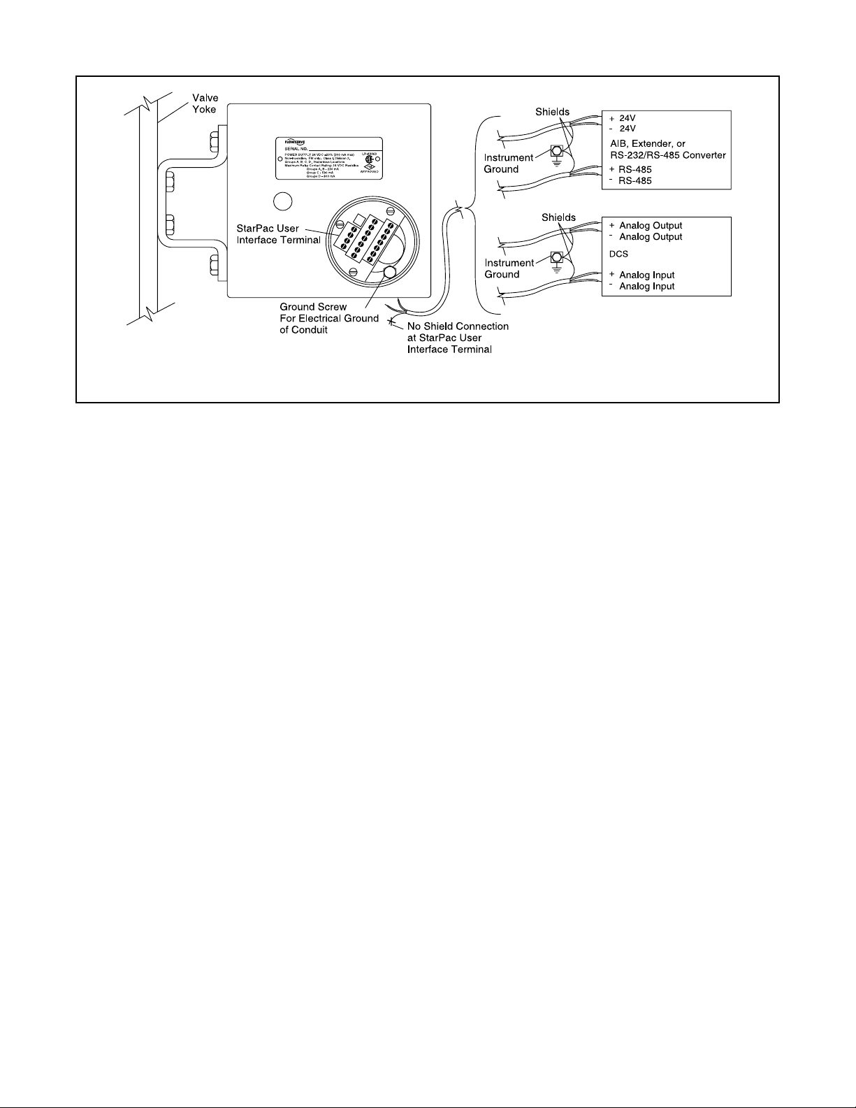
Figure 1: Shielded Wire Diagram
Wiring and Grounding Guidelines
This section will help achieve a maximum 'noise-free'
environment and performance with a StarPac unit.
Shielding Versus Grounding
All signals to the StarPac system should be in shielded
cables. Shields must be tied to a ground at only one end
of the cable to provide a place for environmental electrical noise to be removed from the cable. A ground wire
unlike a shield is attached at both ends to provide a
continuous path for electrical conductivity.
Grounding Screw
The green grounding screw by the user interface terminal block should be used to provide the unit with an
adequate and reliable earth ground reference. This
ground should be tied to the same ground as the
electrical conduit. Additionally, the electrical conduit
connecting to the StarPac unit should be earth grounded
at both ends of its run. The green grounding screw
must not be used to terminate signal shield wires.
24VDC Power
The 24VDC connection points will work best with
shielded twisted pair wire with the shield wire connected only at the source. The input power is isolated
within the StarPac system and may be referenced to
whatever level is necessary. The 24VDC power sup-
ply should not be connected to earth ground.
RS-485 Communication
RS-485 wiring requires the use of a shielded twisted
pair cable, which is grounded only at the source and not
in the StarPac unit. (For maximum performance, wire
should have a characteristic impedance of 120 ohms.)
These signals are referenced to the StarPac internal
system ground; hence this is the main fault path should
one of the isolation points fail. Therefore, care must be
taken to ensure the RS-485 cable is wired correctly.
The RS-485 allows only a 7 to 12V common mode
voltage differential between stations. Flowserve's
Valtek RS-232 to RS-485 converter is not a grounded
connection. PCs with internal RS-485 cards, on the
other hand, are often grounded. If another ground
communication device is on the network, a fault condition will almost certainly exist due to transient and
steady state differences in ground potential.
4 - 20 mA Command Input, Auxiliary Input, and
Feedback Output
These signals are isolated, but shielded twisted pair
wire should be used to reduce crosstalk from other
signals. The shield should be connected only at the
source.
4 - 20 mA I/P Output
This signal is not isolated from the StarPac internal
system ground and will provide a fault path if the I/P or
connecting wires become grounded. Shielded twisted
pair wire should be used with the shield connected in I/P.
Discrete Inputs and Outputs
These signals are isolated, but because they are frequently used to switch high voltage (120VAC), they
should be run in separate shielded wire paths away
from the other StarPac signals.
AIB and RS-232 to RS-485 Converter Connection
When connecting a StarPac system to a communication device, no shield or ground connections exist.
Hence, the 24VDC power and RS-485 communication
shield drain wires must be connected to a convenient
ground near the AIB or converter.
41-2 Flowserve Corporation, Valtek Control Products, Tel. USA 801 489 8611
Page 3
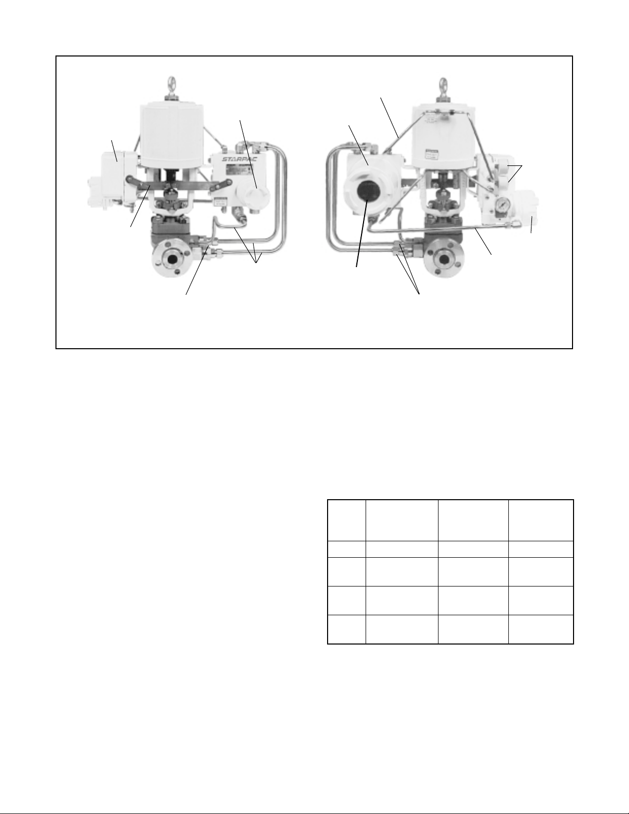
XL Positioner
Positioner
Sensor Arm
User Access
Terminal Cap
Actuator Pressure
Sense Tubing
Electronics
Housing
Actuator
Pressure
Gauges
I/P Module
Electrical
Conduits
Thermocouple
Figure 2: StarPac Intelligent Control System Components
Wiring The StarPac System
All electrical connections must be done according to
local and industry electrical codes. Flowserve recommends a shielded cable be used for the RS-485 command signal wire (i.e., Belden 9841 or equivalent).
When connecting multiple StarPac systems, a parallel
daisy-chain wiring pattern is used. Connect the StarPac
branch lines to the main line, keeping branch lines as
short as possible. The total length of wiring should not
exceed 4,000 feet (1,200 meters) without the use of
repeaters.
Avoid devices producing electrical 'noise' while installing
the cable.
CAUTION: The following procedure should be
performed on the bench or with the unit isolated so
that unexpected valve stroking will not adversely
affect the process.
WARNING: The following procedures may cause
the valve to stroke, causing pressures and
temperatures to vary from their norms. Notify
appropriate personnel that the valve may stroke
unexpectedly. Flowserve suggests that the
system be isolated from the process, if installed
in line.
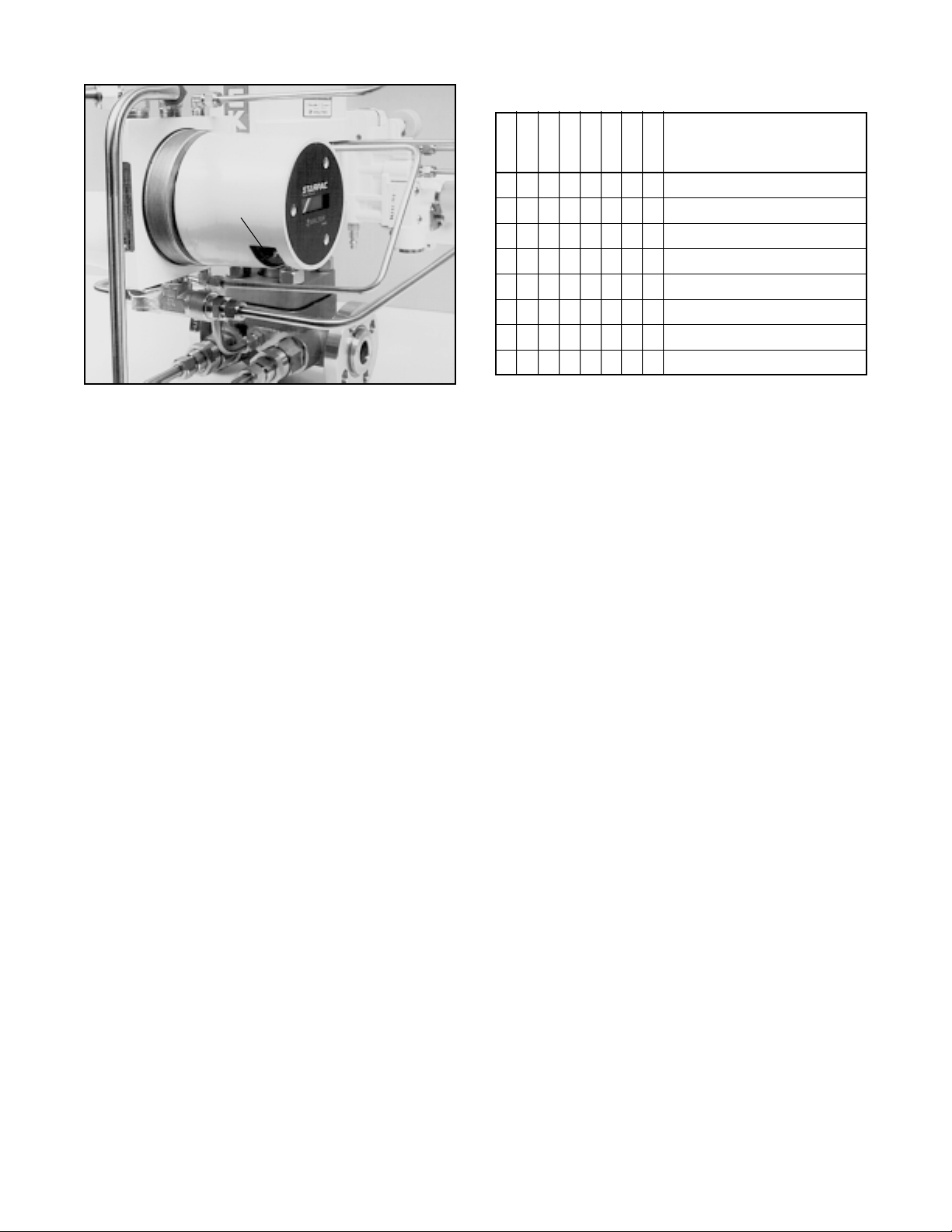
Four StarPac system models are available: SP, SPJS
SPJD and NT. The electronics model for a system is
most easily identified by the face plate of the local
display. If the black cover of the face plate has printed
information with an 'ABC' table for the display parameters, the system contains SP electronics package.
4/20 mA Electrical
Local Display
Process Pressure Sensors
Conduit
If the black cover of the face plate shows only the
StarPac and Valtek logos, the system is an SPJS,
SPJD, or NT unit. The SPJS and SPJD models are
identical except that the SPJD version has two Modbus
ports. To tell the difference, remove the cover on the
user access terminal. If the user interface terminal block
has 18 connections, the unit is a SPJS electronics
package; if the terminal block has 20 connections, it is
the SPJD or NT package.
resU
ledoM yalpsiDlacoL
ecafretnI
kcolB
PS ylnOciremuN slanimreT81 klaTratS
SJPS ciremunahplA slanimreT81 rofklaTratS
DJPS ciremunahplA slanimreT02 rofklaTratS
TN ciremunahplA slanimreT02 rofklaTratS
NOTE: StarTalk and StarTalk for Windows® interface
software packages use different communication protocols and are not compatible. Contact a Flowserve representative for more information about upgrade options
To connect the wiring to the StarPac system, refer to
Figures 1, 2, 3 and Table I, and proceed as follows.
1. Remove the StarPac user interface housing cover
(small cap).
erawtfoS
swodniW
swodniW
swodniW
.
41-3Flowserve Corporation, Valtek Control Products, Tel. USA 801 489 8611
Page 4
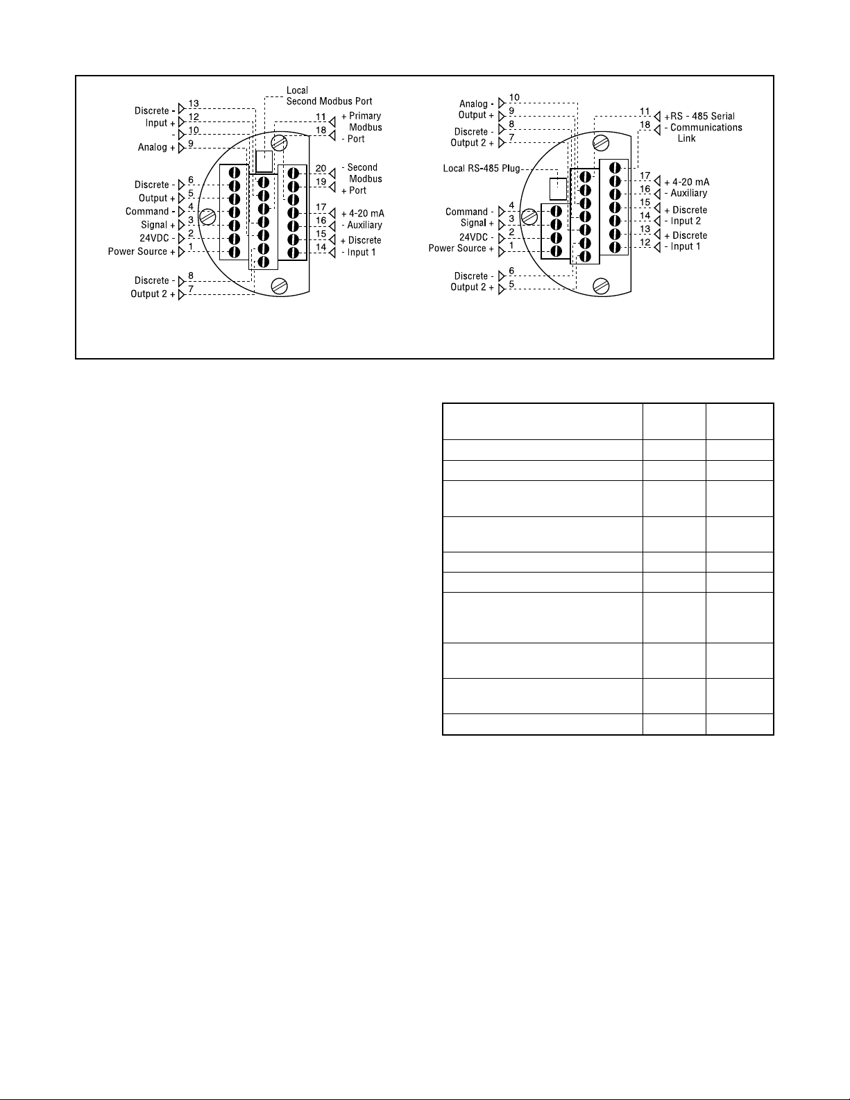
Model SPJD, NT Model SP, SPJS
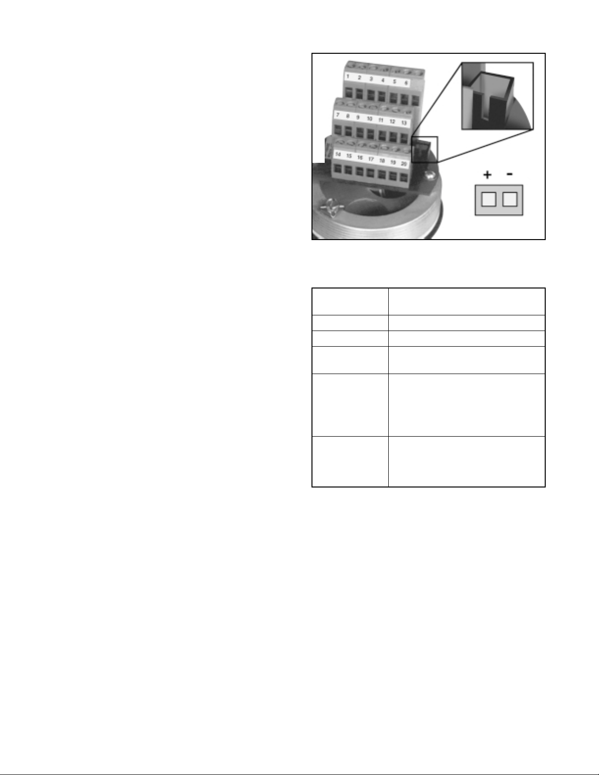
Figure 3: User Interface Terminal Pinouts
WARNING: Do not remove the electronic
housing cover in flammable atmospheres;
otherwise possible injury to personnel or equipment may occur.
2. Connect the required wires to the terminal interface
block and computer as described in Figure 3 and
Table I. (The system must have 24 VDC power and
signal cable for operation.)
NOTE: The StarPac system remembers the operating mode setting (automatic or manual) from the
last time the unit had power. When power to the
system is turned on again, the unit will resume
operation in the previous mode.
Normally the StarPac system arrives from the factory set in the manual operating mode. This means
a command signal will position the valve the same
as a conventional control valve, providing a plug
position proportional to the 4 - 20 mA signal.
To avoid upsetting the process because of improper operating mode selection:
• Ensure that the system arrived from the factory with
the proper operating mode setting in the shop prior
to installation by connecting the air supply and
command signal, then turning on the power and
looking at the mode value on the local display, or;
• Set the proper operating mode for the particular
application in the shop prior to installation by selecting the desired operating mode from the Tuning/
Tune screen in the StarTalk software, or;
• Ensure that the block valves in the process line
around the StarPac system are closed and the
process is diverted around the unit.
3. Turn on the 24 VDC power to the unit, and verify that
the StarPac system has been correctly wired by
checking the following:
• 24 VDC power is at least 300 mA and between
21.6 and 27.0 VDC
Table I: User Interface Terminal Connections
Signal Positive Negative
Term.No. Term. No.
24 VDC power 1 2
Valve command signal 3 4
Primary RS-485 11 18
communication link (Port A)
RS-485 communication 19 20
link (second / Port B)
Auxiliary input (4 - 20 mA) 17 16
Analog output (4 - 20 mA) 9 10
Discrete input 1 – switch/ 13 12
solenoid monitoring (discrete
mode source input)
Discrete input 2 – switch/ 15 14
solenoid monitoring
Discrete output 1 5 6
(malfunction alarm contact)
Discrete output 2 (special) 7 8
• Polarity is correct
• Local display is on; if not, check the power supply
or reset switch
The StarPac local display should now be on, indi-
cating the following:
• Valve stem position
• Setpoint signal
• Process flow value (gas or liquid)
• Temperature of process
• Upstream (P1) and downstream (P2) pressures
At this point the StarPac unit is installed and will
operate as a conventional control valve receiving a
4 - 20 mA command signal from a DCS, or other
device, and stroking the valve accordingly.
41-4 Flowserve Corporation, Valtek Control Products, Tel. USA 801 489 8611
Page 5
Before additional work can be done with the StarPac
system (configured, calibrated and operation mode
changed, etc.) a RS-485 communication cable must
be connected to the unit and RS-485 communication port on a computer with the StarTalk software.
See the StarPac manual for more information.
4. Replace the StarPac user interface housing cover.
System Default Configurations
StarPac systems are shipped from the factory ready for
installation and operation. Rarely do the units need to be
reconfigured prior to operation. Table II lists the factory
default communication/failure mode settings. If these
settings are not correct for the equipment being used,
proceed to the following sections.
Table II: Factory Default Mode Settings
Description Setting
Address 1
Parity odd
Baud Rate 19,200
Modbus Communication RT U
Mode
RS-485 Termination Installed
Resistor
Failure Mode Setting Pass through command
signal on loss of power
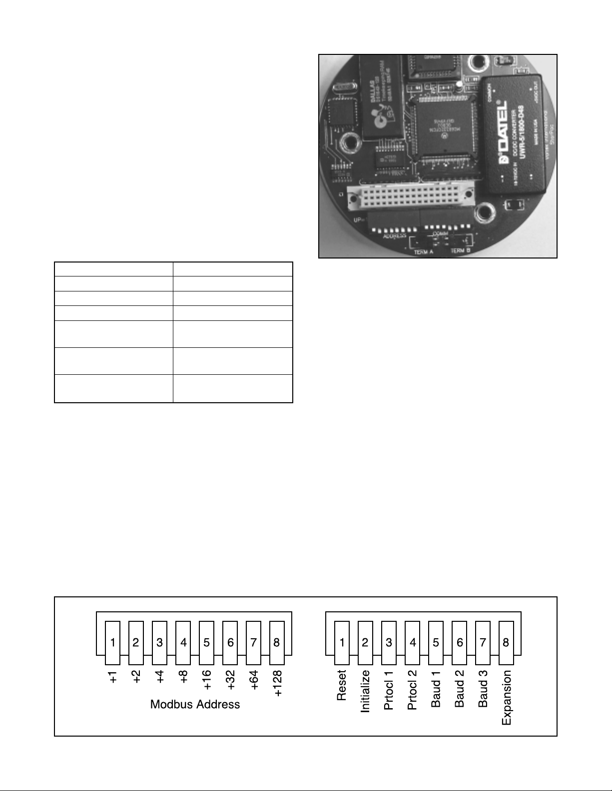
Figure 4: Dip Switch Blocks
Selecting Correct Baud Rate Setting
StarPac systems support baud rates of up 57,600 baud.
However, both the StarPac system and StarTalk software are shipped from the factory set to 19,200 baud.
If the default baud rate setting needs to be changed, refer
to Figures 4 and 5, Table IV and Changing Communication Settings section, and make the necessary change.
Selecting Correct Address Setting
If the StarPac system is the only unit on the communication network, the default address (1) is acceptable.
If multiple StarPac systems will be operating on the
same communication network, each unit must have a
unique address. Before changing the address, use the
StarTalk software to determine what other devices are
on the existing line. (Remember to include devices that
may be temporarily off line.)
If the default address setting needs to be changed, refer
to Figures 4 and 5, Table III and Changing Communication Settings section, and make the necessary change.
Selecting Correct Modbus
Transmission Mode
Two transmission modes exist in a Modbus system,
ASCII and RTU (default). Use the ASCII mode when
transmitting information through a device that uses
ASCII control codes; for example, a modem. Use the
RTU mode when connecting directly to both devices; for
example, an RS-485 interface card wired directly to a
StarPac system.
If the default Modbus transmission mode setting needs
to be changed, refer to Figures 4 and 5, Table IV and
Changing Communication Settings section, and make
the necessary change.
Figure 5: Dip Switches with Labels
41-5Flowserve Corporation, Valtek Control Products, Tel. USA 801 489 8611
Page 6
Dipswitch
access slot
Table III: Address Dip Switch Settings
Switch no. on address block
12345678
1
1 Adds 2 to address value
1 Adds 4 to address value
1 Adds 8 to address value
1 Adds 16 to address value
1 Adds 32 to address value
1 = up = off
0 = down = on
Adds 1 to address value
1 Adds 64 to address value
1 Adds 128 to address value
Figure 6: Dip Switch Access
Selecting Proper RS-485 Termination
Resistor Setting
A termination resistor must be installed on the two most
remote devices on the network, counting the host computer as any other device.
(For example, a single StarPac system and the RS-485
driver in the host computer would each require the
termination resistor to be installed. If four StarPac
systems were on the network with a host computer,
decide which of the two devices have the most combined cable length between them. These two devices
should have the termination resistors installed. The
termination resistors should be disabled in the devices
not considered to be the most remote using the instructions in the next section. Using more than two termination resistors in a network can cause the RS-485 communications to operate erratically or fail.)
If the RS-485 termination resistor needs to be changed,
refer to Figure 5, Table IV and Changing Communication
Settings section, and make the necessary change.
Changing Communications Settings
If the StarPac system communication settings (address, parity, baud rate, Modbus transmission mode,
and RS-485 termination resistor) need to be changed;
refer to Figures 4 and 5 and Table IV and proceed as
follows.
WARNING: Never remove the StarPac electronics
housing cover in explosive atmospheres; otherwise,
nearby personnel and equipment could be injured.
CAUTION: Properly ground yourself before handling
the sensitive StarPac electronics; otherwise unseen
damage to components may occur.
1. If the StarPac system is installed in line, make sure
that taking it and the valve off line will not adversely
affect the process.
NOTE: Down means toward the circuit board; up means
away from the circuit board.
2. Turn off the 24VDC power to the StarPac System.
3. Remove the large cover from the StarPac electronics housing. (See Figure 2.)
4. Make the required dip switch changes (address,
parity, baud rate, and Modbus transmission mode)
according to Tables III and IV. These switches are
visible through the window cut in the lower side of
the shroud. (See Figure 5.)
a. The first dip switch block (marked address)
defines the Modbus address of the StarPac
system using binary coded decimal numbers
(switch 1 = 1; 2 = 2; 3 = 4 ; 4 = 8; 5 = 16; 6 = 32;
7 = 64; 8 = 128). The switches that are up (off
condition) define the address, refer to Table III.
For example, set address 11 by putting switches
1, 2, and 4 (1 + 2 + 8 = 11) up (off condition) and
3, 5, 6, 7, and 8 down (on condition).
b. The second dip switch block sets the parity,
baud rate and Modbus transmission mode.
NOTE: This block also contains initialization and
reset switches described later. Parity changes are
also done by using the switches marked PRTOCL
1 and 2 as shown in Table IV.
c. Set the baud rate by using the switches marked
BAUD 1, 2, and 3 as shown in Table IV.
d. Set the Modbus transmission mode with the
switch marked EXPAN. When the switch is up
(off), the transmission mode is RTU. When the
switch is down (on), transmission mode is ASCII.
NOTE: If the StarPac unit has a dual communication
port (model SPJD or NT), the single set of DIP
switches configures both ports. All of the communication parameters are the same including the address
of two ports. The identical address settings should
not conflict because separate ports are isolated
and independent for use on different networks.
41-6 Flowserve Corporation, Valtek Control Products, Tel. USA 801 489 8611
Page 7
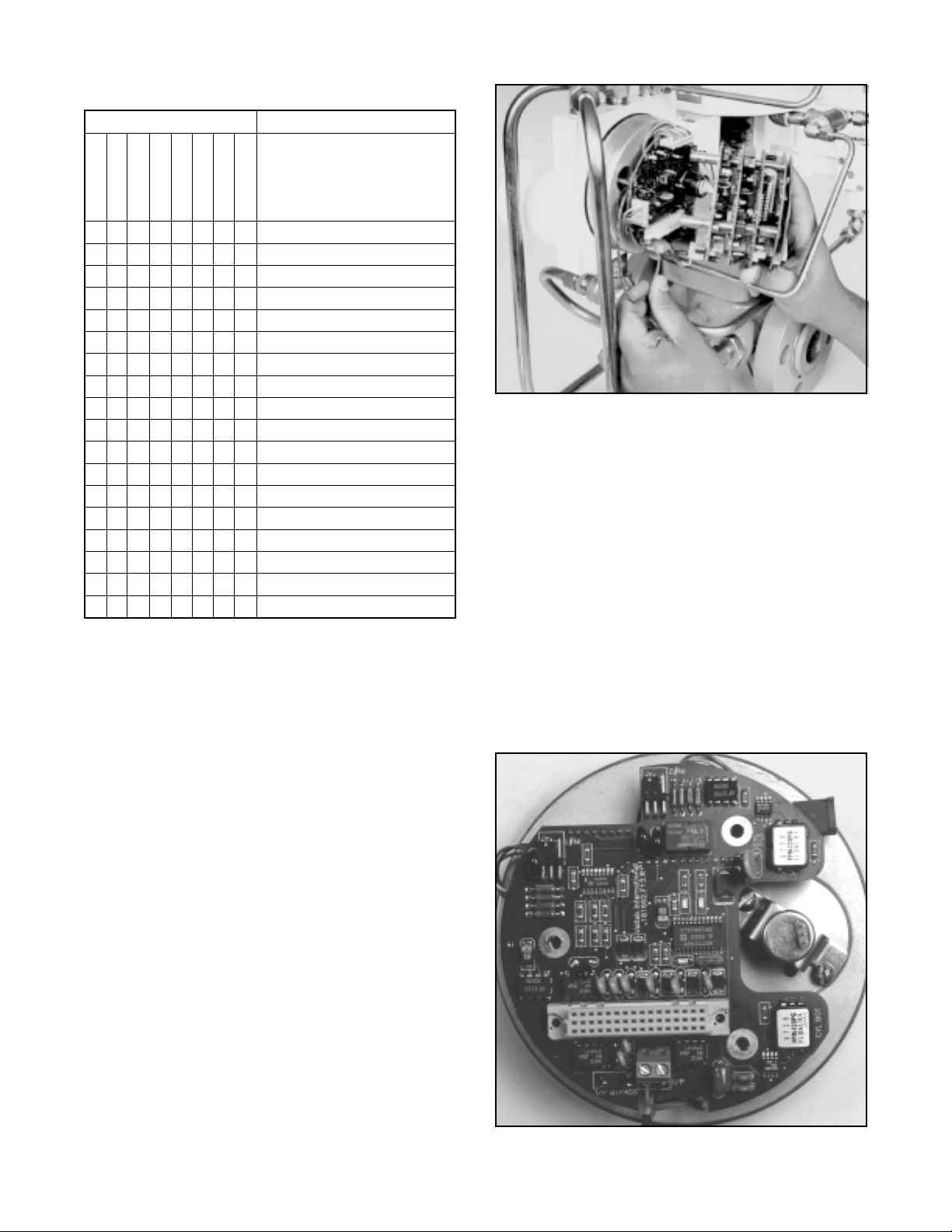
Table IV: Protocol Dip Switch Settings
Switch Label Description
Reset
Init
Protocol 1
Protocol 2
Baud 1
Baud 2
Baud 3
Expan
0 Reset (halt processor)
1 Normal Operation *
0 Initialize on Startup
1 Normal Startup
0 0 No Parity
1 0 Even Parity
0 1 No Parity
1 1 Odd Parity *
0 0 0 Invalid
1 0 0 1200 Baud Rate
0 1 0 2400 Baud Rate
1 1 0 9600 Baud Rate
0 0 1 19200 Baud Rate *
1 0 1 31250 Baud Rate
0 1 1 38400 Baud Rate
1 1 1 57600 Baud Rate
0 ASCII Trans. Mode
1 RTU Trans. Mode *
* default factory settings
5. The jumper for the termination resistor labeled
TERM (see Figure 4) is located at the end of the
protocol dip switch block. Place the jumper over
both pins if the termination resistor is needed, and
over one pin for storage if it is not.
NOTE: If the StarPac unit has a dual communication port (model SPJD or NT) the termination resistor jumper for the second port is located 90 degrees
clockwise from the jumper described above and
can only be accessed by removing the white protective plastic shroud from the electronics assembly. Note second port jumper only needs to be set
according to requirements of the second network.
6. When the required communication settings have
been made, replace the white shroud (if removed)
and the large StarPac electronic housing cover.
Figure 7: Removing Board Stack
the power failure setting as described below. (Refer to
Figures 2, 6, 7 and 8.)
WARNING: Never remove the StarPac cover in
explosive atmospheres; otherwise potential injury
may result to personnel and equipment.
CAUTION: Properly ground yourself before handling
the StarPac electronics; otherwise the sensitive
components may be damaged.
1. If the StarPac system is currently installed in-line,
make sure that the StarPac system (including valve)
can be taken off line in the current process.
2. Turn off the 24-volt power supply and disconnect
the supply air to the StarPac valve.
3. Remove the large electronic housing cover from
the StarPac unit.
Changing the Power Failure Setting
On loss of power, the StarPac is factory set to pass the
command signal to the I/P (unless ordered otherwise).
This configuration causes the system to assume a
traditional control valve mode and respond to an external
4 - 20 mA command signal. During loss of power and if
the application warrants, the StarPac system can be
configured to fail using the fail-safe spring(s) inside the
cylinder actuator. This is accomplished by changing
Figure 8: NT Failure Jumper Location
41-7Flowserve Corporation, Valtek Control Products, Tel. USA 801 489 8611
Page 8
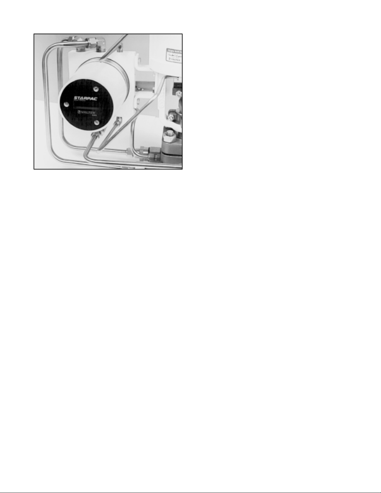
Figure 9:
Shroud Retaining Screws / Local Display
4. Remove the white plastic protective shroud from
the electronic assembly by removing the two screws
from the display end of the assembly. For NT units,
locate the jumper I/P Bypass at the edge of Analog
board number 1. (Refer to Figure 8 and proceed to
step 9.)
5. Next, for SP units only, remove the third screw that
holds the board stack in place.
6. Carefully grasp the computer boards and gently
pull them away from the housing.
7. Locate the jumper on the bottom board (shown in
Figure 8), labeled J105. Remove the jumper from
the two pins and reinsert it onto only one pin for
storage if wanting the valve to fail immediately per
the actuator fail-safe spring configuration. To reactivate the manual failure mode place the jumper
over the two pins labeled J105.
8. Carefully reinstall the top four computer boards
onto the assembly. Be certain the computer board
connector pins are lined up and securely attached
to the bottom board connector. Be certain the top
boards are in line with the bottom board.
9. Replace the protective shroud, install and tighten
the three computer board assembly retaining
screws.
10. Replace the StarPac electronics assembly cover.
Resetting or Initializing the StarPac
The 'Reset' and 'Initialize' switches are the first two dip
switches on the second switch block (see Figure 4). On
rare occasions it may be necessary to reset or initialize
the embedded software program on the StarPac system to stop abnormal operation or clear persistent
errors. This includes errors sometimes caused by brief
power interruptions, or resetting the software after
changing the EPROM.
The reset switch forces the StarPac system through the
startup and diagnostics sequence that the system normally goes through on system power up, and it initializes the program execution to the starting instruction.
The startup sequence also checks internal CPU registers and all of the volatile and nonvolatile RAM. While
initializing the system the local display shows the version number of the EPROM currently installed in the
system. The last thing done by a reset is to clear and
initialize the watchdog timer on the CPU.
A reset can be done by powering the unit down for five
seconds or more and reconnecting the power, or by
resetting the system by pushing the 'Reset' switch down
(on) for five seconds and then moving the switch back
up (off).
NOTE: If the reset switch is left down (on) the CPU will
be halted until the switch is moved up (off).
The 'Initialize' switch (no. 2 or labeled INIT on the PC
board) resets some of the internal work registers to
known values and resets the EPROM checksum. The
switch also sets the command or setpoint source to
receive a 4 - 20 mA analog signal. The 'Initialize' switch
is only accessed by the CPU during a reset.
An initialization is done by setting the INIT switch
down (on) and then resetting the CPU as described
above. After an initialization the system is left in the
calibration mode, which is an out of service mode,
meaning that the system will not respond to normal
commands. StarTalk software must be used to put
the system back into an operating mode. The command or setpoint source must also be reset to
digital if that is the normal operating source.
If the INIT switch is left down (on), the system will
startup in the calibration mode each time power is lost
to the unit or the Reset switch is put in the on position.
This feature can be beneficial if it is desired to manually
reset the system after a power outage to ensure safe
startup.
If the system must be reset using the dip switch as
described above or initialized, refer to Figure 4 and
proceed as follows:
1. Make sure that the StarPac system and valve can
be taken off line without disrupt the process.
2. Remove the large cover from the StarPac electronic housing.
WARNING: Never remove the StarPac cover in
explosive atmospheres; otherwise potential
injury may result to personnel and equipment.
41-8 Flowserve Corporation, Valtek Control Products, Tel. USA 801 489 8611
Page 9
3. Perform the desired actions as described above to
reset or initialize the system.
CAUTION: Properly ground yourself before
handling the StarPac electronics; otherwise the
sensitive components may be damaged.
4. Replace the StarPac electronic housing cover.
Reading Local Display
The local display on StarPac models SPJS, SPJD or NT
displays two lines of information about the system and
the process. The top line of the display has two functions: the left side is a description of the variable
displayed on the second line. The right side of the top
line has information on the current mode of operation
MAN = manual, AUT= automatic, and CAL = calibrate
(or out of service), OVR = over range, TRP = tripped.
Figure 10: Local RS-485 Connector
The second line of the local display shows process or
valve information as configured using the StarTalk II
software.
An 'A' flashing on the right side of the display indicates
there currently is an alarm condition. An 'E' flashing
indicates an error condition. Generally at this point,
these problems are caused by one or more of the
following three conditions:
1. Air supply is not turned on to system
2. The 4 - 20 mA signal is not turned on, or is not being
received by system.
3. The system has just been initialized or is operating
in the calibration mode. The alarm signal will cease
when the system is reconfigured or set to the proper
mode.
For more information, refer to StarPac manual section
on alarms and errors.
Adjusting Display View
The StarPac alphanumeric local display has an adjustment to allow some changes to the display for optimum
visibility.
WARNING: Never remove the StarPac cover in
explosive atmospheres; otherwise potential injury
may result to personnel and equipment.
CAUTION: Properly ground yourself before
handling the StarPac electronics; otherwise the
sensitive components may be damaged.
This adjustment is made by removing the plastic shroud
and adjusting the blue trim potentiometer until the
display is visible. Replace the plastic shroud, secure in
place and replace the large StarPac electronic housing
when done.
Table V: Hardware Specifications
Power Supply 24 VDC ±10%, 300 mA
maximum
RS-485 length Up to 4000 feet (22-26 AWG)
4–20 mA input 232 ohms, 500 V isolation
4–20 mA up to 750 ohm load, 500 V
output drive isolation
Output contact 1 amp at 110 VAC (for Division
rating II areas the ratings are reduced
to 24VDC resistive load: Groups
A & B- 230 mA; Group C- 590
mA; Group D- 800 mA)
Discrete inputs 26.6 kohm, 75 V DC or AC
(peak-peak) rising, 22 V DC or
AC (peak-peak) falling with
180 V maximum.
Local RS-485 Connector
A local RS-485 connector is located on the user terminal block (Figure 9) to allow ease of direct field interfacing to the StarPac system. This connection is a parallel
connection to the RS-485 port terminals (11, 18) on the
user interface terminal block. On StarPac models
SPJD and NT, this is connected only to Port B.
NOTE: The StarPac can only communicate to one
master device on a communication port. When using
the local interface, one of the RS-485 screw interface
wires may need to be disconnected to prevent a conflict
in communications.
A plug connector is available from the factory that will
allow an interface cable to be established. (Request
Part No. 83213.FOT from Flowserve Advanced Product Development Group.) The connector’s crimp terminals are made for 22-26 AWG wire. Note the correct
polarity of the terminals as shown in Figure 9.
41-9Flowserve Corporation, Valtek Control Products, Tel. USA 801 489 8611
Page 10

Procedure for Upgrading to StarPac NT
Prior to making this upgrade, make sure that a current
copy of the system's .CCT file is saved and available.
Refer to the StarTalk software manual for details about
saving configuration tables if unfamiliar with this procedure. Those converting from older SP DataStream
models will first need to save a .TBL file for the system
and then use the Flowserve Advanced Product Development Configuration File Conversion Utility program
for Windows to convert the old parameter table to a
compatible Modbus file. Follow the prompted procedure to make this conversion.
NOTE: This file must be created by a StarTalk 2.0x
version. (Please contact a Flowserve representative
with any questions.)
The upgrade kit consists of the following parts: StarPac
NT boardstack w/EPROM, NT User Interface Assembly, Hallpot Mounting Bracket and new StarTalk software. (If upgrading from an SP DataStream Model, a
plastic shroud should also be included.)
Upgrade Instruction
1. Disconnect all power sources and air supply to the
unit.
2. Disconnect all wiring to the user terminal block of
the StarPac. (Mark each wire pair for ease of reinstallation into new terminal block.)
3. Remove the large electronics cap (turn counter
clockwise) and take off the plastic shroud by removing the three assembly screws from the electronics
module.
4. Remove the old electronics module by first unplugging the top three circuit boards. Remove the next
board by carefully disconnecting the eight-wire
pressure sensor connector from the bottom of the
board and the three-wire hallpot connector from the
top of the hallpot. Unplug the board from the remaining bottom board. Remove the last board by
disconnecting all of the interface connectors and
thermocouple wires. Next, use a 11/16-inch allen
wrench to loosen the hallpot shaft connector set
screw. Rock the board slightly while pulling straight
out from the board to disengage the actuator pressure sensors from their standoffs and the hallpot
shaft.
5. Remove the three screws attaching the use interface terminal block to the base. Pull the old interface wiring back through the base. (Twist the two
white plastic connectors against the wires and push
them into the hole in the base while pulling from the
terminal block side.)
6. All of the old StarPac electronics and user terminal
have now been removed. The pressure cables,
thermocouple wires, and the black and red two-wire
I/P cable should be left on electronic side of the
base.
7. Cut off the small white two-pin connector from the
I/P cable, leaving between 11/2 to 13/4-inch of the
cable extending from the base. Strip the wire ends
approximately 1/4-inch.
8. Remove the hallpot position sensor from the old
StarPac board by removing the 1/2-inch nut and
locking washer. Discard the fiber washer. Attach
the hallpot into the new mounting bracket by aligning the three connector pins on the top of the hallpot
with the notched leg of the new mounting bracket.
The shaft of the hallpot extends into the 'U' of the
bracket.
CAUTION: Over tightening the mounting nut
will put excessive strain on the metal case of the
hallpot and may cause damage.
9. Begin installing the new NT components by first
replacing the new user terminal block. This is done
by gently twisting the two brown connectors back
against the attached wires and pushing these connectors through the hole in the base from the small
cover side to the large electronics side. Replace
the three small mounting screws to secure the user
terminal block to the base.
10. Attach the new hallpot mounting bracket by first
removing the screw that is nearest to the center of
the base. The un-notched end of the hallpot bracket
uses this screw hole. Loosen the opposite screw
three full turns to allow the notched end of the
bracket to swing into place under the screwhead.
Insert the hallpot shaft into the coupling. Rotate the
bracket into place and reinsert the removed screw.
Check that the coupling is centered in the base
hole and does not touch the sides of the hole
before tightening the screws.
Do not tighten the
hallpot shaft set screw at this time.
The coupling cover is spring loaded to provide a
positive force on the feedback arm and this method
allows installation of the bracket without affecting
the spring load.
11. Unplug the new NT bottom board from the rest of
the stack. Plug the two interface connectors from
the user interface into their appropriate connectors
on the bottom of this board. Twisting the connector
once, prior to plugging it into the board, will keep the
wires bundled together and out of the way. Also,
folding the wires flat against the base will keep them
from pushing the board away from the base.
12. Carefully align the two actuator pressure transducer nipples into their pressure standoffs and
press firmly on the top of the two transducers to seat
41-10 Flowserve Corporation, Valtek Control Products, Tel. USA 801 489 8611
Page 11

them into the standoffs and hold the board in place.
The board is properly seated when the pressure
standoffs are almost flush against the bottom of the
board.
CAUTION: Do not twist or bend the board once
the nipples are plugged in or they may break.
Using one of the assembly screws to hold the
board in alignment while attaching the other
wires and boards will help prevent this.
13. Attach the I/P cable wires to the two-screw terminal
block marked 'I/P,' (red wire to the positive terminal
and black wire to the negative terminal). Notice that
this is a plug-in terminal block and may be unplugged without removing the wires.
14. Detach the second NT board from the new stack.
Attach the three-wire hallpot harness from the new
stack into the hallpot connector. The small 'ears' on
the outer edges of the new brown plug should point
to the outside edge of the hallpot.
15. Plug the process sensor connector into the J4
connector on the bottom of this board. On older
StarPac models this connector is a single soldered
eight-pin connector. The more recent models have
two sensor cables which are terminated separately
with crimped on pins and a brown housing. For the
separated cable arrangement, be sure to plug the
correct sensor into the correct half of the board
connector (P1 to P1 and P2 to P2 section).
16. Plug the board into the bottom board mounted on
the base while making sure all pins are aligned.
Use an assembly screw to temporarily hold the
board in place.
17. Attach the thermocouple wires to the two-screw
terminal block on this board, noting the correct
polarity. Red wire to 'R' and yellow wire to 'Y.' If
additional wire length is needed, gently pull more
wire from the base. Also, bend the wires close to
the terminal block (excessive looping is not needed
due to the notches cut in the boards).
18. Plug in the remaining boards. (Be sure to check the
alignment of the pins.) Secure the board stack
together by placing the one spacered assembly
screw in the upper right hand corner.
19. Set the dip switches on the digital board to match
the settings on the old board stack.
NOTE: This step does not apply when upgrading
from the DataStream model.
20. Reaffirm that all connections are properly aligned
and secure.
21. Reattach field wiring to the user interface terminals.
22. Apply 24 VDC power. The liquid crystal display
should display the version number and then the
default display mode.
23. Establish communications and use the StarTalk
software to upload the saved .CCT file for this
system into the new NT module. (If updating from
an older StarPac DataStream model, use the file
conversion utility to convert the old .TBL file into a
compatible Modbus file.)
24. With the air supply shut off, the valve should be
either fully closed or fully opened, depending on the
failure spring action ordered. Use the configuration
menu to set the LCD to display the position continuously. Rotate the hallpot shaft until the displayed
value for position is within a few percentages of
either zero percent (if the valve is closed) or 100
percent (if the valve is open). Tighten the hallpot
connector set screw. (
to the set screw is difficult due to the alignment of
the takeoff arm, connect the air supply and stroke
the valve 50 or 100 percent open as indicated on
the valve stroke plate. Adjust the hallpot shaft to an
indicated position reading of 50 or 100 percent,
then tighten the set screw. Care must be taken if
this method is used to ensure that the ADC values
of the position feedback do not go out of range at
either end of stroke.) Once this has been adjusted
correctly, if the boardstack needs to be replaced,
redoing the setting is not needed unless the hallpot
itself is damaged.
Alternate method
: If access
NOTE: If the position values displayed decrease
rather than increase when the valve strokes open,
the three-wire hallpot connector is reversed and
needs to be unplugged and rotated 180°.
25. Replace the plastic shroud and the remaining two
assembly screws. Make sure all wiring is beneath
the shroud and that no wires are trapped between
the bottom board and the vibration isolators in
which the assembly screws attach.
26. Turn the air supply back on to the actuator.
27. After verifying that stroking the valve is safe, use
the calibration menu to first recalibrate the actuator
pressure sensor, and then perform a valve stroke
calibration. During this calibration, watch the position ADC values to ensure that the hallpot adjustment is not at its limit on either end of stroke. (If
needed, readjust the hallpot shaft setting to keep
the shaft rotation within the operating range of the
hallpot, then recalibrate.)
28. Secure both the large electronics and the smaller
interface covers.
29. Use the StarTalk software to calibrate the process
sensors and verify the other operational parameters of the system.
Do not forget to reconfigure the
LCD to display the desired variables.
30. Return the system to operation.
41-11Flowserve Corporation, Valtek Control Products, Tel. USA 801 489 8611
Page 12

SYSTEM MAINTENANCE
Flowserve recommends that the StarPac system calibration and maintenance work be done once every six
months. If after checking the calibration of the StarPac,
a component is determined to be defective the following
section will help with the component replacement.
The following items may be needed to install, start up
and calibrate the StarPac system electronics.
• Power supply: 24 VDC regulated ±2.4 VDC, 300 mA
• StarTalk software (proper version for the electron-
ics being used)
• Computer with internal or external RS-485 communication adapter
• RS-485 connection cable
• Digital volt meter with 4 - 20 mA range
• Air supply: 50 psig (3.4 bar) minimum, 80 - 100 psig
(6.3 - 7.8 bar) preferred; coalescing air filter required
• Gauges or the ability to accurately determine process pressures and valve air supply pressures
• 4 - 20 mA command source
• Thermocouple calibrator or simulator with 0 - 932°
Fahrenheit (0 to 500° Celsius) range
Mechanical Subsystem Maintenance
Refer to the appropriate Flowserve Installation, Operation & Maintenance (IOM) instructions for details on the
repair and maintenance of the control valve positioner
and actuator components. Please refer to the manufacturers’ manuals for maintenance and operation instructions for non-pneumatic actuators, e.g., electric or
electro-hydraulic actuators.
At first glance the additional tubing and connections of
the StarPac system may appear to make standard
valve maintenance more difficult and complex. The
following instructions will show a maintenance method
that will make this task much easier. Please note that
most of the additional tubing attached to the StarPac
system is electrical conduit and does not contain process fluid.
WARNING: The process line must be depressurized and drained of process fluid, and decontaminated prior to working on the internal valve components. Failure to do so may cause serious injury to
personnel.
1. Depressurize the line, decontaminate the valve (if
needed) and shut off the air supply to the valve
positioner.
2. Disconnect the four actuator air tubes from the
positioner and StarPac system.
3. Disconnect the four mounting bolts that attach the
StarPac system bracket and positioner bracket.
4. Disconnect the follower arms from the StarPac
base and positioner. This is done by removing the
follower arm nut and washer and pulling the arm off
the shaft. Notice that this shaft connection is keyed
and that the shafts are slightly spring loaded.
5. The actuator subassembly is now isolated and is
removed by loosening the bonnet bolts and lifting
the actuator away from the body.
The StarPac system tubing holds the StarPac base
and positioner in place, eliminating the need to
disconnect wiring or air connections.
6. Standard valve maintenance may now be done on
the actuator or valve body components. Refer to
the Flowserve IOM instructions for details on such
things as trim or packing replacement. If the trim
needs to be replaced, use the same trim number
and characteristic as the original trim, or the flow
calculations could be affected. If a trim size change
is needed, contact a Flowserve representative to
find out about flow calibration options.
7. Reassemble the system by reversing the above
steps. Be sure to follow the procedures outlined in
the Flowserve IOM instructions for valve reassembly. Make sure when reconnecting the follower
arms that the arms fit correctly on the keyed shafts
and have a positive spring action.
8. Turn on the air supply to the valve and check for
leaks in the reattached actuator tubing lines. Check
the calibration of the positioner for proper operation. Refer to Flowserve IOM 24 instructions for
details on calibrating the Beta positioner.
9. Turn on power to the StarPac system. Use the
StarTalk software to check the system calibration
and do a valve stroke calibration to reset the
StarPac’s position feedback. Refer to the Calibration section of the StarPac manual.
Position Feedback System
The position feedback linkage of the StarPac system is
a critical part of the flow metering ability of the system.
This linkage is used to calculate the valve’s CV for a
given stroke. This linkage should be lubricated and
checked periodically for tight, smooth operation. The
follower arm should operate smoothly with no binding
and have a positive spring loading on the arm. Inspect
the follower arm pin for excess wear and replace if
needed. The takeoff arm attached to the stem clamp
must be firmly secured to the stem clamp and perpendicular to the actuator stem. If this takeoff arm is canted
or misaligned, problems may occur with positioner
calibration and the position reading on the StarPac may
go out of range.
On rotary actuators, make sure the adjustment linkage
locknut is tight and has no excessive play in the ball
joints. The rotary shaft clamp must be tight and should
not freely rotate on the shaft.
41-12 Flowserve Corporation, Valtek Control Products, Tel. USA 801 489 8611
Page 13

Figure 12: Board Removal
Figure 11: Disconnecting Lemo Connector
Pressure Sensor Replacement
Standard StarPac pressure sensors are installed
directly into the control valve body. Before they can be
removed, the process line must be depressurized and
drained of all fluids and the valve decontaminated.
To replace a pressure sensor, refer to Figure 10 and
proceed as follows.
WARNING: The process line must be depressurized
and drained of process fluid, and decontaminated
prior to working on the internal valve components.
Failure to do so may cause serious injury to
personnel.
WARNING: If optional pressure sensor extensions
are included, the sensor will be located in a sensor
housing located in the tubing line and not in the
sensor housing located on the valve body. This
section of the tubing contains process fluid and
must be drained and decontaminated before the
sensor is removed. The procedure for sensor
removal and replacement will be similar to that
outlined below.
(Refer to alternate sensor information when this type of
sensor is included with system.)
1. Depressurize and decontaminate the line and valve.
Loosen the tubing nuts on the conduit leading to the
pressure sensor, if applicable.
2. Loosen the sensor nut.
3. Gently pull the conduit and sensor nut approximately 1/2 to 3/4-inch from the sensor. Release the
locking sleeve of the Lemo™ connector by moving
the collar away from the sensor (use needle nose
pliers). Remove the connector from the sensor and
swing the sensor conduit out of the way.
4. Unscrew the sensor from the sensor boss.
5. Remove the sensor O-ring or gasket and replace
with a new one. Make sure the environmental
O-ring seal is in good condition and in place on the
new sensor.
6. Install the new sensor into the sensor port making
sure the O-ring or gasket remains properly in place
while tightening the sensor. Tighten the sensor
until it seats metal-to-metal at the gasket section of
the sensor port, assuring the proper compression
of the process O-ring or gasket seal.
7. Align the red dots on the sensor and connector, and
reconnect the Lemo connector. Fully seat the
connector until the locking sleeve latches. Replace
the sensor nut and tighten.
8. Pressurize the valve body to make sure the sensors are properly seated before attaching the sensor conduit and tightening.
9. Reattach the conduit lines and securely tighten the
fittings.
Temperature Sensor Replacement
(Model NT)
The StarPac temperature sensor (middle sensor on the
valve body) does not penetrate the wall of the control
valve; therefore, replacement does not require that the
process line be drained.
To replace a StarPac temperature sensor, refer to Figure
14 and proceed as follows:
1. Disconnect the power and air supply to the unit.
2. Remove the large StarPac electronics assembly
cover.
WARNING: Never remove the StarPac's electronics assembly covers if explosive atmospheres are present.
3. Remove the plastic shroud by unscrewing the two
assembly screws.
4. Unplug the temperature wires from the computer
board and undo the thermocouple wire.
41-13Flowserve Corporation, Valtek Control Products, Tel. USA 801 489 8611
Page 14

5. Loosen the conduit nuts containing the temperature sensor wire. Remove the conduit, pulling the
sensor wires out of the tubing.
6. Remove the temperature sensor by unscrewing it
from the body.
7. Screw the new sensor into the body. Tighten firmly.
8. Reinstall the stainless steel fitting and conduit,
feeding the sensor wire through to the StarPac
computer board.
9. Cut the temperature wire about 31/2-inches from
the StarPac housing. Strip the wire about 1/4-inch
from the end.
10.Reconnect the temperature wires to computer board.
11. Replace the StarPac electronics assembly shroud
and secure the two-board assembly screws. Assure that no wires are trapped between the bottom
circuit board and the rubber vibration isolators.
12. Turn on the power supply to the unit again.
Warning: Do not turn on (energize) the StarPac
unit in explosive atmospheres with the assembly cover removed. Injury to personnel could
result.
13. Communicate to the system using the StarTalk
software and verify the data for that particular valve.
14. Replace the large StarPac cover and restore the air
supply to the unit.
15. Check the sensor calibration.
Temperature Sensor Replacement
(Model SPxx)
The StarPac temperature sensor (middle sensor on the
valve body) does not penetrate the wall of the control
valve; therefore, replacement does not require that the
process line be drained.
To replace a StarPac system temperature sensor, refer
to Figures 2, 12, 13, and 14 and proceed as follows.
1. Disconnect the power and air supply to the unit.
2. Remove the large StarPac electronics assembly
cover.
WARNING: Never remove the StarPac electronics assembly cover if explosive atmospheres
are present; otherwise, injury to personnel can
occur.
3. Separate the top four boards from the bottom
computer board, by first removing the three computer board assembly screws and sliding off the
plastic shroud. Carefully grasp the top four computer boards and pull them away from the bottom
board while holding it in place. Disconnect the
three-wire hallpot and eight-wire pressure sensor
harness connectors and set the four boards aside.
4. Disconnect the temperature sensor wires from the
terminal block 'J102' on the bottom computer board.
5. Loosen set screw on the hallpot base connector.
6. Disconnect the three remaining wire harness connections and carefully remove the bottom computer
board from the StarPac system housing base.
Some resistance will be felt as the air-pressure
connections disengage.
7. Loosen the conduit nuts containing the temperature sensor wire. Remove the conduit, pulling the
sensor wires out of the tubing.
8. Remove the temperature sensor by unscrewing it
from the body.
9. Screw the new sensor into the body. Tighten firmly.
10. Reinstall the stainless steel fitting and conduit,
feeding the sensor wire through to the StarPac
computer board.
11. Install the bottom computer board on StarPac system housing base, being careful to connect the two
air-pressure connections and hallpot arm to their
appropriate places. Do not tighten the set screw
now. Reconnect the three wire harness connections. Cut new temperature sensor wire to length
and attach it to terminal block, noting polarity.
12. Reattach the remaining top four computer boards,
being certain to reconnect the two wire harness
connections and the interface connections.
13. Replace at least one of the three computer board
assembly screws and tighten to hold stack in place.
14. Turn on the power supply to the unit again.
WARNING: Do not turn on (energize) the StarPac
unit in explosive atmospheres with assembly
cover removed. Injury to personnel may result.
15. Communicate to the system using StarTalk software and verify the data for that particular valve.
16. Use the
set the local display to show
hallpot shaft (arrow in Figure 13) within five percent
of the valve's actual position. (Since the valve's air
supply is shut off, this will be either 100 percent
open or closed.) Tighten the hallpot set screw.
17. Replace the StarPac electronics assembly shroud
and secure the three board assembly screws.
Assure that no wires are trapped between the
bottom circuit board and the rubber vibration
isolators.
18. Replace the StarPac electronic housing cover and
restore the air supply to the unit.
19. Check the sensor calibration, following the procedure outlined in the Calibration section of the StarPac
manual, if needed. A stroke calibration will need to
be done to finish calibrating position feedback; refer
to the StarPac manual.
Configuration
menu of StarTalk software to
Position
. Adjust the
41-14 Flowserve Corporation, Valtek Control Products, Tel. USA 801 489 8611
Page 15

Three-wire position
sensor cable
Eight-wire pressure
sensor cable
Set
screw
Figure 13: Removing Top Four Boards
Board Stack Replacement (Model NT)
Inside the electronic housing cover and under the white
plastic shroud of a StarPac unit are five printed circuit
boards, together referred as the board stack. This design
allows each board to have a single purpose, which
simplifies troubleshooting and diagnostic procedures.
(Refer to Figure 7 on page 7.)
If, after consulting with the local Flowserve or factory
representative, the StarPac system's computer board
stack is found defective and needs replacement, proceed as follows. (Prior to proceeding, make sure a copy
of the configuration .CCT file is saved and available.)
1. Disconnect the power and air supply to the unit.
2. Remove the StarPac electronics assembly cover.
WARNING: Never remove the StarPac electronics assembly cover if explosive atmospheres
are present; otherwise, injury to personnel can
occur.
Figure 14: Position Sensor Alignment
(Model SPxx)
the user interface into their appropriate connectors
on the bottom of this board. Twisting the connector
once prior to plugging it into the board will keep the
wires bundled together and out of the way. Also,
folding the wires flat against the base will keep them
from pushing the board away from the base.
7. Carefully align the two actuator pressure transducer nipples into their pressure standoffs and
press firmly on the top of the two transducers to seat
them into the standoffs and hold the board in place.
The board is properly seated when the pressure
standoffs are almost flush against the bottom of the
board.
CAUTION: To avoid damaging the nipples, do
not twist or bend the board once the nipples are
plugged in.
to hold the board in alignment while attaching
the other wires and boards will help prevent
this.)
(Using one of the assembly screws
3. Remove the plastic shroud by unscrewing the three
board assembly screws. Carefully grasp the top
four computer boards and pull them away from the
bottom board holding it in place. Disconnect the
three-wire hallpot and eight-wire process harness
connectors and set the four computer boards aside.
4. Unplug the temperature sensor wires from the
terminal block marked 'T /C ' on the second computer board.
5. Disconnect the three remaining wire harness connections and carefully remove the bottom computer
board from the StarPac housing base. Some resistance will be felt as the air pressure connections
disengage.
6. Unplug the new NT bottom board from the rest of
the stack. Plug the two interface connectors from
Figure 15: Thermocouple Installation
41-15Flowserve Corporation, Valtek Control Products, Tel. USA 801 489 8611
Page 16

8. Attach the I/P cable wires to the two-screw terminal
block marked 'I/P.' (Red wire to the positive terminal and black wire to the negative terminal.)
9. Detach the second NT board from the new stack.
Attach the three-wire hallpot harness from the new
stack into the hallpot connector. The small 'ears' on
the outer edges of the new brown plug should point
to the outside edge of the hallpot.
10. Plug the board into the bottom board, mounted on
the base, making sure all pins are aligned. Use an
assembly screw to temporarily hold the board in
place.
11. Plug the thermocouple wires into the two-screw
terminal block on this board, noting the correct
polarity. Red wire to 'R' and yellow wire to 'Y.' If
additional wire length is needed, gently pull more
wire from the base. Also, bend the wires close to
the terminal block (excessive looping is not needed
due to the notches cut in the boards).
12. Plug the process sensor connector into the J4
connector on the bottom of this board. On older
StarPac models this connector is a single soldered
eight-pin connector. On more recent models have
two sensor cables which are terminated separately
with crimped on pins and a brown housing. If the
cable arrangement has been separated, be sure to
plug the correct sensor into the correct half of the
board connector (P1 to P1 and P2 to P2 section).
13. Plug in the remaining boards. (Be sure to check the
alignment of the pins.) Secure the board stack
together by placing the one spacered assembly
screw in the upper right hand corner.
14. Set the dip switches on the digital board to match
the settings on the old board stack.
15. Reaffirm that all connections are properly aligned
and secure.
16. Apply 24 VDC power. The liquid crystal display
should display the version number and then the
default display mode.
17. Establish communications and use the StarTalk
software to upload the saved .CCT file for this
system into the new NT module.
18. Replace the plastic shroud and the remaining two
assembly screws. Make sure all wiring is beneath
the shroud and that no wires are trapped between
the bottom board and the vibration isolators in
which the assembly screws attach.
19. Turn the air supply back on to the actuator.
20. After verifying that stroking the valve is safe, use
the calibration menu to first recalibrate the actuator
pressure sensor, and then perform a valve stroke
calibration. During this calibration, watch the posi-
tion ADC values to ensure that the hallpot adjustment is not at its limit on either end of stroke. (If
needed, readjust the hallpot shaft setting to keep
the shaft rotation within the operating range of the
hallpot, then recalibrate.)
21. Secure both the large electronics and the smaller
interface covers.
22. Use the StarTalk software to calibrate the process
sensors and verify the other operational parameters of the system.
23. Return the system to operation.
Board Stack Replacement (Models SPxx)
Inside the electronic housing cover and under the white
plastic shroud of a StarPac unit are five printed circuit
boards, together referred to as the board stack. This
design allows each board to have a single purpose,
which simplifies troubleshooting and diagnostic
procedures.
If, after consulting with the local Flowserve or factory
representative, the StarPac system’s computer board
stack is found defective and needs replacement, refer
to Figures 2, 7, 13 and 14 then proceed as follows.
NOTE: Make sure a current copy of the configuration
file exists.
1. Download or find a backup copy of .CCT File.
2. Disconnect the power and air supply to the unit.
3. Remove the StarPac electronics assembly cover.
WARNING: Never remove the StarPac electronics assembly cover if explosive atmospheres
are present; otherwise, injury to personnel can
occur.
4. Remove the plastic shroud by unscrewing the three
board assembly screws. Carefully grasp the top
four computer boards and pull them away from the
bottom board holding it in place. Disconnect the
three-wire hallpot and eight-wire process harness
connectors and set the four computer boards aside.
5. Disconnect the temperature sensor wires from the
terminal block marked 'J102' on the bottom computer board.
6. Loosen the set screw on the hallpot base connector. Refer to Figure 13.
7. Disconnect the three remaining wire harness connections and carefully remove the bottom computer
board from the StarPac housing base. Some resistance will be felt as the air pressure connections
disengage.
8. From the new computer board stack, install the
bottom computer board on the StarPac device
41-16 Flowserve Corporation, Valtek Control Products, Tel. USA 801 489 8611
Page 17

housing base, being careful to connect the two airpressure connections and hallpot arm to their appropriate places. Do not tighten the set screw
now. Reconnect the three wire harness connections. Attach the temperature sensor wires to the
terminal block, noting polarity.
9. Reattach the remaining top four computer boards,
being certain to reconnect the two wire harness
connections. Properly line up and fully seat the
interface connections.
10. Replace at least one of the three computer board
assembly screws and tighten to hold the stack in
place.
11. Turn on the power supply to the unit again.
WARNING: Do not turn on (energize) the StarPac
unit in explosive atmospheres with the assembly cover removed. Injury to personnel may
result.
12. Use the StarTalk software to apply a stored configuration table for the StarPac unit. Refer to the
Technician Support section of the StarPac manual
for details.
13. Use the Configuration menu of StarTalk software to
set the local display to show Position. Adjust the
hallpot shaft (arrow in Figure 14 within five percent
of the valve’s actual position (since the valve’s air
supply is shut off, this will be either 100 percent
open or closed). Tighten the hallpot set screw.
14. Replace the StarPac electronics assembly shroud.
Tighten the three shroud retainer screws. Restore
the air supply to the unit.
15. Replace the StarPac electronics housing cover.
16. After the new computer boards have been replaced, the unit will need to be recalibrated following the procedures listed in the Calibration section
of the StarPac manual. Use Stroke Calibration
Section to finish calibrating the position feedback.
17. Reset the operational parameters to bring the system back into service.
EPROM Replacement
Occasionally the need may arise to replace the EPROM
of the StarPac. The EPROM contains the operating
program code for the StarPac system. (If the StarPac
system has a special feature or custom program
EPROM, ensure that the new electronics board stack
has the proper EPROM.) The EPROM from the old
board can be traded with the EPROM on the new board
if needed. If the digital board of the faulty system is
suspected to be damaged, a replacement EPROM can
be ordered from a Flowserve representative. The bill of
material for the system will contain the unique part
number for the special EPROM.
If the EPROM needs to be replaced, refer to Figures 4
and 5 then proceed as follows.
CAUTION: This procedure should only be done by
personnel trained in the proper handling of sensitive electronic components.
1. Make sure the valve is either by-passed or in a safe
condition.
2. Turn off the 24 VDC power to the StarPac and air
supply to the actuator.
3. Remove the StarPac electronics housing cover.
WARNING: Never remove the StarPac electronics assembly cover if explosive atmospheres
are present; otherwise, injury to personnel can
occur.
4. Remove three circuit board assembly screws and
lift the protective shroud off the board assembly.
5. Carefully unplug the local display board (top) from
the rest of the board assembly. This exposes the
digital board with the EPROM. The EPROM is
located in a square holder at the edge of the board.
6. Remove the old EPROM by using a PLCC extraction tool. Notice that two opposite corners of the
EPROM socket are slotted. The fingers of the tool
slide all the way into these slots. The fingers of the
tool should catch under the corners of the EPROM.
Squeeze the tool to extract the EPROM and pull it
out from the socket.
7. Carefully remove the new EPROM from its protective carrier. Handle the EPROM carefully by the
corners and use whatever anti-static precautions
are available. A typical method is to keep one hand
on a grounded metal item and handle the device
with the other hand. The static sensitive device is
protected once it is in its socket. Notice that the
EPROM has one corner trimmed, one top edge
beveled, and a dot cast into the top. Align the
EPROM in the socket so that the dot and beveled
edge face the small square silk-screened on the
edge of the PC board. The trimmed corner should
be on the left as shown by the silk-screen outline.
CAUTION: The StarPac contains sensitive electronic components. Use proper antistatic
(grounding) precautions when handling the
EPROM and insert properly or the EPROM may
be damaged.
8. Firmly press the EPROM into the socket. It should
be slightly below the edges of the socket to be fully
seated.
9. On the dip switch, located next to the bus connector, set switch 2 INIT on by toggling the switch down.
10. Carefully plug the top display board back on the
stack making sure all pins are aligned in the bus
socket.
41-17Flowserve Corporation, Valtek Control Products, Tel. USA 801 489 8611
Page 18

11. Replace the protective shroud over the board assembly, aligning the window in the shroud over the
display. Make sure none of the interconnection
wiring at the base of the board assembly protrudes
outside the shroud. Replace the three circuit board
assembly screws and tighten snugly.
12. Turn the power on to the StarPac system. Toggle
the 2 INIT switch back to its up position. (This can
be reached from the side of the board and does not
require removing the display board again.) The
local display should display zeroes on SP models
or the word 'CAL' on SPJ and NT models.
13. Replace the StarPac electronic housing cover.
14. Restore power to the StarPac and the air supply to
the actuator.
15. The StarPac system can now be connected with the
StarTalk software to make whatever configuration
changes are needed.
The system has been reset to its initialization defaults. The StarPac will remain in a startup test
mode, signified by zeroes on the local display or
CAL, until the system is connected to the StarTalk
software for the first time. The non-volatile RAM
containing the system’s parameter table is not
affected by changing EPROMs so recalibration
should not be needed. Because of the internal
initialization that takes place in the StarPac unit
when this procedure is done, an error can be
detected during the reset. This will be cleared and
may be ignored if it is not ongoing (signified by a
continuously flashing error display).
16. The system now can be returned to service.
Table VI: StarPac Accessories
noitpircseD rebmuN
,584SR/232SR,retrevnoC
CAV022,011
ecafretnIgolanAcaPratS
CDV42,)lennahC8(
NID,ylppuSrewoP
otCAV011,detnuom-liar
CDV42
36955001
70296001
91597001
Table VII: Linear Actuator Follower Arms
eziSrotautcA
)sehcni(
52
52
52
52
05
05
05 3 26.2 41673001
001
001
001 8-5 57.4-83.3 61673001
ekortS
)sehcni(
1
/4 00.2 97834001
3
/8 00.2 97834001
1
/2 00.2 31673001
3
/4 1-1/2 00.2 31673001
1
/2 1-1/2 00.2 31673001
1
/2 2-1/2 26.2 11144001
3
/4 3- 88.2-26.2 41673001
3
/4 4- 57.4-83.3 51673001
dupS
)sehcni(
tiKmrArewolloF
41-18 Flowserve Corporation, Valtek Control Products, Tel. USA 801 489 8611
Page 19

27
28
23
22
18
26
25
24
20
21
19
13
17
16
15
14
12
11
10
8
6
9
7
29
3
1
5
Item Description
1. Large cap
2. Glass cap
3. Retaining ring
4. Large O-ring
5. Electronic stack screws
6. Bushing
7. Shroud
8. StarPac Electronics
9. Hallpot feedback sensor
10. Hallpot bracket
11. Hallpot screw
12. Spring bracket
13. Spring
4
14. Set Screw
15. Helical Coupling
16. Feedback shaft
17. Vibration isolator
18. Feedback shaft O-ring
19. Pressure Connector
20. Flame Arrestor
21. Groove pin
22. Mounting bracket
23. Mounting bolt
24. Valve yoke
25. Housing
26. Retaining ring
Figure 16: Exploded View
2
27. Follower arm
28. Follower pin
29. Lock washer
30. Follower pin nut
31. User interface terminal
32. User interface screws
33. Small cap O-ring
34. Small cap
41-19Flowserve Corporation, Valtek Control Products, Tel. USA 801 489 8611
Page 20

StarPac Spare Parts Kits
See StarPac exploded view (Figure 16) for item numbers.
Kit 1 - StarPac Housing Replacement
Part No. 10055770
.oNmetI noitpircseD ytitnauQ
1 pacegraL 1
2 pacssalG 1
3 gnirgniniateR 1
4 gnir-OpacegraL 1
11 swercskcatscinortcelE 2
21 tekcarbgnirpS 1
31 gnirpS 1
41 wercsteS 1
51 gnilpuoclacileH 1
61 tfahskcabdeeF 1
71 rotalosinoitarbiV 3
81 gnir-O 1
91 rotcennocerusserP 2
02 rotserraemalF 2
12 nipevoorG 2
52 gnisuoH 1
62 gnirgniniateR 1
33 gnir-OpacllamS 1
43 pacllamS 1
Kit 5 - NT Shroud Replacement Kit
Part No. 10070583
.oNmetI noitpircseD ytitnauQ
5 swercskcatscinortcelE 3
6 gnihsuB 1
7 duorhS 1
Kit 6 - NT Electronics Upgrade Kit
Part No. 10202761
.oNmetI noitpircseD ytitnauQ
5 swercskcatscinortcelE 3
6 gnihsuB 1
7 duorhS 1
8 kcatsscinortceleTN
MORPE/w
01 tekcarbtopllaH 1
11 swercstopllaH 2
13 lanimretecafretniresU 1
23 swercsecafretniresU 3
1
NOTE: If hallpot is required, order hallpot replacement
kit (Kit 4).
Kit 2 - NT Electronics Replacement Kit
Part No. 10059202
.oNmetI noitpircseD ytitnauQ
5 swercskcatscinortcelE 3
6 gnihsuB 1
8 kcatsscinortceleTN
MORPE/w
Kit 3 - NT User Interface Replacement Kit
Part No. 10059203
.oNmetI noitpircseD ytitnauQ
13 lanimretecafretniresU 1
23 swercsecafretniresU 3
Kit 4 - Hallpot Replacement Kit
Part No. 10059205
.oNmetI noitpircseD ytitnauQ
9 rosneskcabdeeftopllaH 2
01 tekcarbtopllaH 1
11 swercstopllaH 1
Kit 7 - Replacement Helical Coupling
Part No. 10052650
.oNmetI noitpircseD ytitnauQ
51 gnilpuoClacileH 1
1
Kit 8 - Follower Pin Assembly for Linear
Actuators
Part No. 10036685
.oNmetI noitpircseD ytitnauQ
82 raenilrofniprewolloF
srotautca
92 rehsawkcoL 1
03 tunniprewolloF 1
Kit 9 - I/P Wire Replacement Kit
Part No. 10055394
noitpircseD ytitnauQ
eriwP/I 1
1
41-20 Flowserve Corporation, Valtek Control Products, Tel. USA 801 489 8611
Page 21

Pressure and Temperature Sensor Spare Part Kits
See Body-mount Sensor Configurations (Figure 17) and
Remote-mount Sensor Configuration (Figure 18) for item numbers.
Pressure Sensor Gasket Kits
NOTE: Kits 1 thru 4 will service two body or two remote-
mount pressure sensors from any one of the pressure
sensor configuration drawing numbers listed below each
table.
Kit 1 - Viton O-ring Replacement Kit
Part No. 10061027
Item No. Description Quantity
6 Environmental O-ring, Viton 2
8 Environmental O-ring, Viton 4
10 O-ring seal, Viton 2
20 Environmental O-ring, Viton 2
21 O-ring seal, Viton 2
Configuration Drawing Numbers: 83883, 83891,
83904, 83884, 83892, 101565, 83887 83900,
127586, 83888, 83901
Kit 2 - Spiral Wound Gasket Replacement Kit
Part No. 10061028
Item No. Description Quantity
6 Environmental O-ring, Viton 2
8 Environmental O-ring, Viton 4
10 O-ring seal, Viton 2
20 Environmental O-ring, Viton 2
21 Spiral wound gasket seal 2
Configuration Drawing Numbers: 83938, 83890,
122670, 83886, 83903, 127563, 83899, 127632
Kit 3 - PTFE Gasket Replacement Kit
Part No. 10061029
Item No. Description Quantity
6 Environmental O-ring, Viton 2
8 Environmental O-ring, Viton 4
10 PTFE gasket seal 2
20 Environmental O-ring, Viton 2
21 PTFE gasket seal 2
Configuration Drawing Numbers: 122513, 127565
Kit 4 - Kalrez O-ring Replacement Kit
Part No. 10061113
Item No. Description Quantity
6 Environmental O-ring, Viton 2
8 Environmental O-ring, Viton 4
10 O-ring seal, Kalrez
20 Environmental O-ring, Kalrez 2
21 O-ring seal, Kalrez 2
™
2
Configuration Drawing Numbers: 83885, 83889,
127665, 83893, 83902
Pressure Sensor Hardware Kits
Kit 5 - Pressure Sensor Connection Kit, Div II
Non-incendive Configuration
Part No. 10061022
Item No. Description Quantity
3 Swagelok nut 2
4 Swagelok ferrules 2
5 Sensor nut 2
6 Environmental O-ring, Viton
7 Division II sensor fitting 2
NOTE: Kit will service two pressure sensors. For
class I, Division II, Group A, B, C, & D.
for Tubing.
Kit 6 - Pressure Sensor Connection Kit,
Div I Configuration
Part No. 10061023
Item No. Description Quantity
13 Division I sensor fitting 2
5 Sensor nut 2
6 Environmental O-ring, Viton 2
NOTE: Kit will service two pressure sensors. For
class I, Division I, Groups B, C, & D.
®
See Table XII
2
41-21Flowserve Corporation, Valtek Control Products, Tel. USA 801 489 8611
Page 22

Kit 7 - Remote Mount Pressure Sensor Hardware Kit
Part No. 10061025
Kit 12 - Pressure Sensor Calibration Kit
Part No. 10061118
Item No. Description Quantity
3 Swagelok nut 4
4 Swagelok ferrules 4
15 Temperature extended fitting 2
19 Adapter fitting 2
NOTE: Kit will service two remote-mount pressure
sensors. See Table XII for tubing. (Wet-leg tubing wall
thickness must be 0.065-inch).
Kit 8 - Remote Mount Pressure Sensor Hardware Kit
with Purge and Isolation Valves
Part No. 10061026
Item No. Description Quantity
3 Swagelok nut 4
4 Swagelok ferrules 4
15 Temperature extended fitting 2
16 Purge valve 2
17 Isolation valve 2
19 Adapter fitting 2
NOTE: Kit will service two remote-mount pressure
sensors. See Table XII for tubing. (Wet-leg tubing wall
thickness must be 0.065-inch).
Description Quantity
Pressure sensor calibration fixture 1
Electrical connector extension cable 2
O-ring seal, Viton 2
NOTE: Two sensors can be calibrated simultaneously
with this kit.
Kit 13 - DP Cell Manifold Replacement
Part No. 10203723
Description Quantity
Valve manifold 1
Temperature Probe Kits
See temperature sensor configurations drawing for
item numbers.
Kit 14 - Standard Temperature Probe Replacement,
Div II Configuration
Part No. 10055955
Item No. Description Quantity
2 Standard temperature probe 1
Kit 9 - Explosion Proof Union Fitting
Part No. 10007238
Item No. Description Quantity
14 Explosion proof union 1
Kit 10 - Pressure Sensor Electrical Cable
Replacement Kit
Part No. 10061117
Item No. Description Quantity
1 Electrical connector cable 1
22 Four-pin connector 1
23 Wire crimp terminal 4
NOTE: Kit will service two pressure sensors.
Kit 11 - Pressure Sensor Electrical Extension Cable
Part No. 10054518
Description Quantity
Electrical connector extension cable 1
Kit 15 - Standard Temperature Probe Replacement,
Div I Configuration
Part No. 10070891
Item No. Description Quantity
2 Standard temperature probe 1
6 Adapter fitting 1
7 Adapter fitting 1
Kit 16 - Through Hole Temperature Probe
Replacement
Part No. 10065272
Item No. Description Quantity
2 Through hole temperature 1
probe
41-22 Flowserve Corporation, Valtek Control Products, Tel. USA 801 489 8611
Page 23

12
11
10
Boss on
valve body
8
13
6
5
14
1
9
8
Item Description
1. Electrical connection cable
2. Tubing, 0.035 wall thickness (see Table XII)
3. Swagelock nut
4. Swagelock ferrule set
5. Sensor nut
6. Environmental O-ring
7. Division II sensor fitting
8. Environmental O-ring
9. Pressure sensor
10. O-ring seal
Figure 17: Body-mount Sensor Configurations
7
6
5
11. Length adapter fitting
12. O-ring seal
13. Division I sensor fitting
14. Explosion-proof union
15. Wire crimp terminals
16. Four-pin connector
4
3
2
15
16
Kit 17 - Pressure Sensor Adaptor Kit
Part No. 10203061
Description Quantity
PTFE cap for flush-mount sensors 1
Kit 18 - Pressure Sensor Adaptor Kit
Part No. 10070892
Description Quantity
Pressure sensor length adapters
w/Viton O-rings 1
Kit 19 - Pressure Sensor Adaptor Kit
Part No. 10070893
Description Quantity
Pressure sensor length adapters
w/spiral-wound gaskets 1
NOTE: In July of 1993, the sensor manufacturer
shortened the process end of the pressure sensors. If
the StarPac uses the longer style sensors, order one of
the above adapter kits with the new sensor purchase.
Each kit will service two pressure sensors.
41-23Flowserve Corporation, Valtek Control Products, Tel. USA 801 489 8611
Page 24

Boss on
valve body
12
11
21
20
22
23
4
5
2
3
19
4
3
18
6
7
8
1
8
10
13
6
9
5
14
16
15
4
3
Item Description
1. Electrical connector cable
2. Tubing 0.035-inch wall,
(see Table XII)
3. Swagelock nut
4. Swagelock ferrule set
5. Sensor nut
6. Environmental O-ring
7. Division II sensor fitting
8. Environmental O-ring
9. Pressure sensor
10. O-ring seal
11. Length adapter fitting
12. O-ring seal
Figure 18: Remote-mount Sensor Configurations
17
3
4
13. Division I sensor fitting
14. Explosion-proof union
15. Temperature extended fitting
16. Purge valve
17. Isolation valve
18. Wet-leg tubing, 0.065-inch wall,
(see Table XII)
4
3
Table IX: Standard Pressure Sensor
noitpircseD
AISP52-0,rosneserusserP 17926001
AISP05-0,rosneserusserP 27926001
AISP001-0,rosneserusserP 75926001
AISP051-0,rosneserusserP 36926001
AISP003-0,rosneserusserP 47926001
AISP005-0,rosneserusserP 56926001
AISP0001-0,rosneserusserP 06926001
AISP0051-0,rosneserusserP 57926001
AISP0003-0,rosneserusserP 77926001
AISP0005-0,rosneserusserP 87926001
AISP0057-0,rosneserusserP 89119001
18
19. Adapter fitting
20. Environmental O-ring
21. O-ring seal
22. Four-pin connector
23. Wire crimp terminals
lairetaMmgarhpaiD
leetSsselniatS613
41-24 Flowserve Corporation, Valtek Control Products, Tel. USA 801 489 8611
Page 25

4
T emperature probe boss
3
Div II Configuration
2
1
7
2
Div I Configuration
Item Description
1. Two-pin connector
2. Temperature probe
3. Tubing, 0.035 wall, (see Table XII)
4. Swagelock tube fitting
146
5
5. Stainless steel pipe
6. Adapter fitting
7. Adapter fitting
14. Explosion-proof union
Figure 19: StarPac Temperature Sensor, Flush-mount Version
1
Table X: 316 Stainless Steel Tubing
noitpircseD
)kcihthcni-530.0retemaidhcni-05.0(gnibuteriwrosneserusserP 30554001
)kcihthcni-560.0retemaidhcni-05.0(gnibutgeltewdednetxeerutarepmeT 48755001
)kcihthcni-530.0,retemaidhcni-8/3(gnibutelpuocomrehtdnaeriwP/I 76331001
On remote mount pressure sensor configurations, the wet-leg tubing must have a wall thickness of 0.065-inch.
lairetaMmgarhpaiD
leetSsselniatS613
41-25Flowserve Corporation, Valtek Control Products, Tel. USA 801 489 8611
Page 26

Figure 20: Sensor Troubleshooting Chart
41-26 Flowserve Corporation, Valtek Control Products, Tel. USA 801 489 8611
Page 27

Troubleshooting StarPac Intelligent Control Systems
Failure Probable Cause Corrective Action
Local display not on 1. 24 VDC not on or set correctly 1. Verify power supply is outputting 24 VDC
(+3 volts) at terminals 1 and 2
2. Incorrect wiring polarity 2. Check wiring for correct polarity
3. Interface connections on bottom 3. Make sure connections are correctly
are not correct aligned and fully plugged in
Local display has black 1. RESET switch was left down or 1. Set RESET switch to up position or boxes
showing dimly system not completely initialized completely reinitialize system
Erratic communications 1. Multiple units have same address 1. Change each unit to a unique, sequential
on network line address (refer to Address Setting in
Maintenance section)
2. Proper polarity not maintained 2. Check all network connections for cor-
rect positive and negative connections
3. Individual units not properly wired 3 . Begin with shortest RS-485 run, check-
ing polarity and communication; continue
checking units throughout network
4. Termination jumper not installed 4. Install termination jumper on two most
distant devices
StarPac does not 1. StarPac still in initialize mode 1. Be certain the INIT switch is up, then
respond to analog change the mode in the tuning screen
commands 2. I/P not connected 2. Be certain the two-wire cable is con-
nected on the bottom board
StarPac data is not 1. Improper configuration file was 1. Find the correct file for this system and
correct loaded onto system send to the StarPac; refer to the Utility
or Technician sections of the StarPac
manual
Valve position reading 1. Hallpot connection not tight 1. Tighten hallpot connection set screw
is not correct 2. Stroke not calibrated 2. Calibrate valve stroke; refer to
Calibration section
3. Hallpot shaft is at end of stroke 3. Readjust hallpot shaft connection; make
sure shaft does not reach rotation stop
in either direction
Stem position 1. Hallpot wiring harness is installed 1. Reverse three-wire harness
decreases when valve backwards
opens
41-27Flowserve Corporation, Valtek Control Products, Tel. USA 801 489 8611
Page 28

Flowserve Corporation has established industry leadership in the design and manufacture of its products. When properly selected, this Flowserve product is designed to perform its intended function
safely during its useful life. However, the purchaser or user of Flowserve products should be aware that Flowserve products might be used in numerous applications under a wide variety of industrial
service conditions. Although Flowserve can (and often does) provide general guidelines, it cannot provide specific data and warnings for all possible applications. The purchaser/user must therefore
assume the ultimate responsibility for the proper sizing and selection, installation, operation and maintenance of Flowserve products. The purchaser/user should read and understand the Installation
Operation Maintenance (IOM) instructions included with the product, and train its employees and contractors in the safe use of Flowserve products in connection with the specific application.
While the information and specifications presented in this literature are believed to be accurate, they are supplied for informative purposes only and should not be considered certified or as a guarantee
of satisfactory results by reliance thereon. Nothing contained herein is to be construed as a warranty or guarantee, express or implied, regarding any matter with respect to this product. Because
Flowserve is continually improving and upgrading its product design, the specifications, dimensions and information contained herein are subject to change without notice. Should any question arise
concerning these provisions, the purchaser/user should contact Flowserve Corporation at any of its worldwide operations or offices.
For more information, contact:
Flowserve and Valtek are registered trademarks of Flowserve Corporation.
For more information about Flowserve, contact www.flowserve.com or call USA 972 443 6500
Regional Headquarters
1350 N. Mt. Springs Prkwy.
Springville, UT 84663
Phone 801 489 8611
Facsimile 801 489 3719
12 Tuas Avenue 20
Republic of Singapore 638824
Phone (65) 862 3332
Facsimile (65) 862 4940
12, av. du Québec, B.P. 645
91965, Courtaboeuf Cedex,
France
Phone (33 1) 60 92 32 51
Facsimile (33 1) 60 92 32 99
Quick Response Centers
5114 Railroad Street
Deer Park, TX 77536 USA
Phone 281 479 9500
Facsimile 281 479 8511
104 Chelsea Parkway
Boothwyn, PA 19061 USA
Phone 610 497 8600
Facsimile 610 497 6680
1300 Parkway View Drive
Pittsburgh, PA 15205 USA
Phone 412 787 8803
Facsimile 412 787 1944
41-28FCD VLAIM041-04 ©1999 Flowserve Corporation. Flowserve Corporation, Valtek Control Products, Tel. USA 801 489 8611
 Loading...