

Page 1

Flow Control Division
Installation, Operation, Maintenance Instructions
Valtek Spring Cylinder
Rotary Actuators
GENERAL INFORMATION
The following instructions are designed to assist in
unpacking, installing and performing maintenance as
required on Valtek® Spring Cylinder Rotary Actuators.
Product users and maintenance personnel should
thoroughly review this bulletin prior to installing, operating or performing any maintenance on the actuator.
Separate maintenance instructions cover additional
components (such as Valdisk and ShearStream body
assemblies, fail-safe systems, limit switches, hand-levers,
position transmitters and handwheels.
This publication does not contain information on
Flowserve positioners. Refer to the appropriate maintenance bulletin for installing, calibrating, maintaining,
troubleshooting and operating Flowserve positioners.
This bulletin contains instructions on maintaining the
clamping and non-clamping splined lever design.
Contact the factory or your Flowserve representative for
more information on the diaphragm seal assembly design.
To avoid possible injury to personnel or
damage to valve parts, WARNING and CAUTION
notes must be strictly followed. Modifying this
product, substituting non-factory parts, or
using maintenance procedures other than
outlined could void warranties, drastically
affect performance and be hazardous to
personnel and equipment.
IMPORTANT
Three designs of the Spring Cylinder Rotary Actuator
exist in service today. The original design contained a
diaphragm seal assembly in the actuator. This assembly
was later replaced with a sliding seal assembly. Lifecycle testing under rigorous conditions shows sliding
seals will last many times longer than diaphragm stem
seals. Made of Delrin 100 and bronze, sliding seals are
durable and much easier to maintain. Since the sliding
seal design has replaced the diaphragm as Flowserve’s
standard, it is highly recommended that the diaphragm
stem seal be replaced with the sliding seal.
The third design uses a standard rotary actuator with
a sliding seal assembly in the actuator and a clamping
lever arm in the transfer case.
Maintenance personnel should become familiar with
the particular rotary actuator design needing service
and follow the appropriate maintenance instructions for
that design.
Unpacking
1. While unpacking the actuator, check the packing
list against the materials received.
2. When lifting the actuator from the shipping container,
position lifting straps and hoist to avoid damage to
tubing and mounted accessories.
WARNING: When lifting an actuator with lifting
straps, be aware the center of gravity may be
above the lifting point. Therefore, support must
be given to prevent the actuator from rotating.
Failure to do so can cause serious injury to
personnel and damage to actuator or nearby
equipment.
3. Contact your shipper immediately for any shipping
damage.
4. Contact your Flowserve representative for any
problems.
Page 2

Installation
Prior to installation, make sure adequate overhead and
side clearance for the actuator is provided to allow for
proper removal and for proper maintenance. Refer to
Table I.
NOTE: If the actuator is attached to a Valtek Valdisk or
ShearStream valve body assembly, see Installation,
Operation, Maintenance Instructions 10 or 27 for
overhead clearances.
Table I: Overhead Clearance for
Disassembly
Actuator Size Minimum Clearance
25 6 inches
50 8 inches
00, 200 9 inches
NOTE: Although Valtek rotary spring cylinder actuators
can be mounted in any position, mounting the cylinder
vertically is the preferred installation.
1. Mount the actuator on the desired valve or other
mechanical device.
2. Connect the air supply and instrument signal air
lines to the two appropriately marked connections
on the positioner. Since both the cylinder and
positioner are suitable for 150 psi air supply, an air
regulator should not be used unless the air supply
exceeds 150 psi.
CAUTION: In some cases, the air supply must
be limited to less than 150 psi. A sticker found
near the upper air port on the actuator cylinder
will indicate this condition.
CAUTION: The transfer case cover plate and
yoke must be mounted on the actuator prior to
it being stroked, otherwise damage will result.
On older designs, the actuator must also be
attached to a valve or other mechanical device.
3. The installation of an air lter on the supply line is
recommended.
4. Make sure all air connections are free of leaks,
using a soap solution.
If an internal problem is suspected with the actuator, refer
to the “Disassembly and Reassembly” section.
1. Examine the actuator for damage caused by
corrosive fumes and process splatter.
2. Clean actuator and repaint oxidized areas.
3. If possible, stroke actuator and check for smooth,
full-stroke operation.
4. Remove the transfer case cover plate and make
sure the positioner linkage and splined lever arm
are securely fastened.
CAUTION: Never apply air to the actuator
without the cover plate installed; otherwise, the
unsupported shaft will sustain damage. Do not
remove the cover plate with the valve in service.
5. Be sure all accessories, brackets and bolting are
securely fastened.
6. If possible, remove air supply and observe the
position indicator plate for correct fail-safe action.
7. Spray a soap solution around the cylinder retaining
ring and the adjusting screw to check for air leaks
through the O-rings.
8. Clean any dir t or other foreign material from the shaft.
9. If an air lter is supplied, check and replace cartridge
if necessary.
Removing Rotary Actuators From
Valtek Valve Bodies
1. Support actuator assembly before disconnecting
it from the body assembly.
2. Remove the actuator cover bolts. Carefully pry or
slide cover plate from the lever arm.
3. On Flowserve actuators with a clamping lever arm
design, loosen the clamp bolt.
4. Loosen the actuator adjusting screw to release
spring pressure.
5. Remove the actuator from the body by separating
the actuator at the yoke. This is done by removing
the four transfer case bolts and pulling the actuator
off the valve shaft.
PREVENTIVE MAINTENANCE
At least once every six months, check for proper operation by following the preventive maintenance steps
outlined below. These steps can be performed while
the actuator is in service and, in some cases, without
interrupting service.
WARNING: Keep hands, hair and clothing away from
all moving parts while operating the actuator. Failure
to do so can cause serious injury.
2
ACTUATOR DISASSEMBLY
Disassembling Actuators with clamping and Nonclamping Lever Arm
If it is necessary to disassemble an actuator with a
non-clamping lever arm, refer to Figures 1 and 2, and
proceed as follows:
1. Depressurize actuator and disconnect all tubing.
2. Relieve the spring compression by removing the
adjusting screw.
Page 3
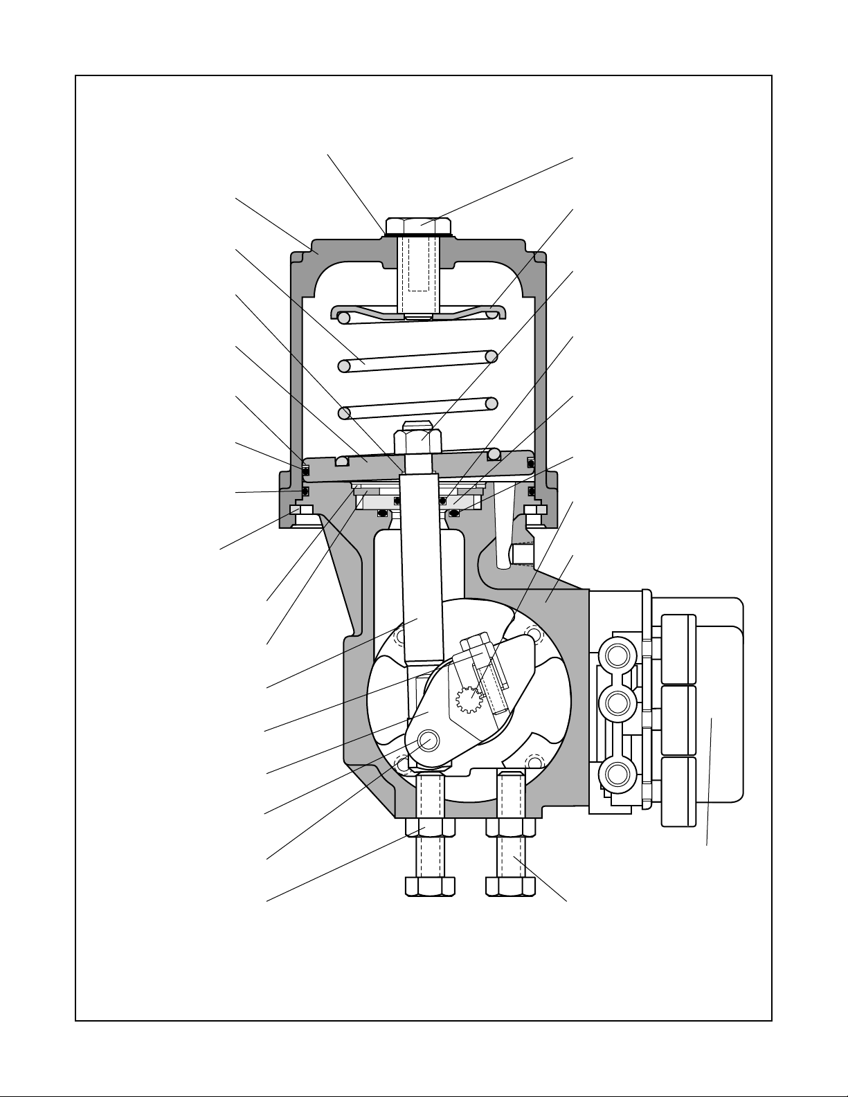
Adjusting Screw Gasket
(Item No. 248)
Adjusting Screw
(Item No. 210)
Cylinder
(Item No. 202)
Spring
(Item No. 229)
Piston Stem O-ring
(Item No. 272)
Piston
(Item No. 225)
Piston Back-up Ring
(Item No. 269)
Piston O-ring
(Item No. 271)
Cylinder O-ring
(Item No. 274)
Cylinder Retaining Ring
(Item No. 256)
Spring Button
(Item No. 227)
Actuator Stem Locknut
(Item No. 348)
Actuator Stem O-Ring
(Item No. 275)
Sliding Seal Collar
(Item No. 366)
Base Slider O-Ring
(Item No. 278)
Valve Shaft
(Item No. 51)
Transfer Case
(Item No. 204)
Spiral Retaining Ring
(Item No. 368)
Retaining Washer
(Item No. 360)
Actuator Stem
(Item No. 211)
Splined Lever Arm
(Item No. 249)
Yoke/Cover Plate Bearing
(Item No. 258)
Lever Arm Bearing
(Item No. 358)
Pivot Pin
(Item No. 361)
Stroke Stop Jam Nut
(Item No. 347)
Figure 1: Sectional View of Actuator with Non-clamping Lever Arm
Note : Item numbers correspond directly to the bill of material; refer to it for specic part numbers.
Beta Positioner
(Item No. 280)
Stroke Stop Bolt
(Item No. 330)
3
Page 4

WARNING: Spring is under compression. Failure
to relieve spring compression by removing
adjusting screw can result in serious personal
injury.
3. Using a screwdriver, remove the retaining ring from
the groove at the base of the cylinder.
4. Pull the cylinder off the transfer case and piston.
NOTE: Substantial O-ring resistance may be felt.
WARNING: Do not use air pressure to remove
cylinder. Personal injury may result.
5. Remove spring button and spring.
CAUTION: Care must be taken not to damage the
sliding seal assembly or actuator stem O-ring
when removing the actuator stem.
6. Remove the actuator stem locknut. The piston and
piston stem O-ring may now be removed from the
actuator stem.
7. Remove the spiral snap-ring holding the sliding
seal assembly in place.
8. Remove the retaining washer and sliding seal
collar. These components can usually be removed
by hand or by gently prying the outside surface of
the collar upward.
WARNING: Do not scratch the bottom surface
of the sliding seal collar with a screwdriver or
sharp object. Scratches can cause excessive
wear and possible leakage.
9. Remove the transfer case cover plate by removing
the four bolts.
10. Remove the yoke from the transfer case by removing
the four lug bolts.
11. Remove the pivot pin from the non-clamping lever
arm by removing a retaining ring.
12. The actuator stem can now be easily removed from
the transfer case.
13. The non-clamping lever arm can be removed by rst
removing the positioner according to the appropriate
positioner maintenance bulletin.
14. If the yoke/cover plate bearings need to be
replaced, press them out of the yoke and/or cover
plate using a press and arbor.
15. The non-clamping lever arm bearings can be
replaced by pressing them out with a press and
arbor.
ACTUATOR REASSEMBLY
Reassembling Actuators with clamping
and Non-clamping Lever Arm
To reassemble an actuator with a non-clamping lever
arm, refer to Figures 1 and 2, and proceed as follows:
1. Clean and lubricate all internal parts. All O-rings
should be replaced and lubricated using a silicone
lubricant (Dow Corning 55M or equivalent). The
bore that houses the sliding seal assembly in the
transfer case must be smooth and clean.
2. If lever arm bearings were removed, install new
bearings by pressing them into place with a press
and arbor.
3. Install lever arm into transfer case through cover
plate/yoke openings.
4. Slide actuator stem through the top opening of
transfer case and connect to the lever arm with
the pivot pin and two retaining rings.
5. If the yoke/cover plate bearings were removed,
press new bearings into the yoke and cover plate
using a press and arbor.
6. On clamping lever design, rmly tighten clamp bolt
on clamping lever arm actuators.
7. Install cover plate and yoke onto transfer case. The
four tapered lug bolts are used with the yoke and
standard hex bolts are used with the cover plate.
8. Install base slider O-ring into sliding seal groove
machined in the transfer case.
9. Install actuator stem O-ring into the sliding seal
collar. Then slide the collar over the actuator stem.
10. Place retaining washer over the collar and install
the spiral retaining ring into the transfer case.
11. Replace the piston O-ring and piston backup ring
onto piston, making certain the piston backup ring
is on top (toward the top of cylinder) of the piston
O-ring.
NOTE: 200 square-inch actuators use two piston
backup rings. They are placed on each side of the
piston O-ring.
12. Install the piston stem O-ring and piston on to the
actuator stem.
13. Install the spring guide (50, 100, and 200 squareinch actuators only) and actuator stem locknut
onto the actuator stem. Tighten the actuator stem
locknut rmly.
14. Install the cylinder O-ring into transfer case groove.
NOTE: Replace cylinder O-ring if damaged.
4
Page 5

201
202
204
210
211
213
225
227
229
238
246
248
249
256
258
271
272
274
275
278
280
330
336
337
347
348
357
358
359
360
361
363
366
368
Item No. Description
201 Yoke
202 Cylinder
204 Transfer Case
210 Adjusting Screw
211 Actuator Stem
213 Stroke Plate
225 Piston
227 Spring Button
229 Spring
238 Follower Pin
246 Yoke Bushing
248 Adjusting Screw Gasket
249 Lever Arm
256 Cylinder Retaining Ring
258 Cover Plate Bushing
269 Piston Backup Ring
271 Piston O-ring
272 Piston Stem O-ring
274 Cylinder O-ring
275 Actuator Stem O-ring
278 Base Slider O-ring
280 Positioner
330 Stroke Stop Bolt
336 Yoke Bolt
337 Cover Plate Bolt
347 Stroke Stop Jam Nut
348 Actuator Stem Locknut
357 Purge Screen
358 Lever Arm Bearing
359 Retaining Ring
360 Sliding Seal Top Clamp
361 Pivot Pin
363 Cover Plate
366 Sliding Seal Collar
368 Spiral Retaining Ring
Figure 2: Exploded View of Actuator with Non-clamping Lever Arm
Note: Item numbers correspond directly to the bill of materials; refer to it for specic numbers.
5
Page 6

15. Install the spring and spring button.
16. Slide cylinder down over piston and transfer case.
CAUTION: The cylinder must be perpendicular
with the piston when sliding it over the piston
O-ring. If this is not done, the O-ring could be
damaged.
3. Cycle the valve open. Adjust the other stroke stop
until valve is 90 degrees from the closed position.
4. Cycle the valve several times to make certain the
position indicator returns to the same position with
each cycle.
5. Tighten the stroke stop jam nuts.
1 7. Reinsert the cylinder retaining ring in the cylinder
by feeding it a little at a time into the groove. Make
sure it is securely fastened.
WARNING: Ensure that the cylinder retaining
ring is completely seated in the cylinder groove,
or serious personal injury may occur.
18. Center the hole in the spring button directly under
the adjusting screw hole. Install the adjusting screw
and tighten only enough to provide an air seal with
the gasket. Do not overtighten.
19. If actuator is to be used with a positioner, mount
positioner and connect tubing.
CAUTION: The actuator cover plate and yoke
must be installed prior to stroking the actuator
or damage will result.
Mounting Rotary Actuators with nonclamping lever Valtek Valve Bodies
When mounting a rotary actuator to a Valtek valve body,
refer to Installation, Operation, Maintenance Instructions 10 in the case of Valdisk, 27 for ShearStream, or
39 for MaxFlo valves. When mounting a rotary actuator
on other manufacturers’ valve bodies, refer to the appropriate literature.
When mounting an actuator with clamping lever arm,
rmly tighten the clamping bolt on the splined lever arm.
Adjusting External Stroke Stops
After disassembly and reassembly it may be necessary to
readjust the external stroke stops to avoid valve leakage.
The external stroke stops should be adjusted while the
valve is out of line. To adjust the external stroke stops,
proceed as follows:
CAUTION: Actuators with clamping lever arms must
be attached to a valve or other mechanical device
and the transfer cover plate must be installed prior
to stroking the actuator or damage will result.
1. Cycle the valve (or mechanical device) to just
beyond the closed position with very low supply
air pressure (10-15 psi).
2. Turn the stroke stop in clockwise (as viewed from
the end) until resistance is felt. Turn the stroke stop
an additional 1/8 turn. Check to see that the valve
is closed on dead center. If not, adjust the stop until
the valve is closed on dead center.
REVERSING THE ACTUATOR ACTION
The rotary actuator transfer case allows for four different
mounting positions and for either fail-close or fail-open
air failure operation, without retubing or changing the
fail-safe spring in the actuator. Before reversing the actuator action, make sure there is no line pressure in the
valve and support the actuator assembly by the lifting
ring. Refer to Figures 1 and 2 and proceed as follows:
NOTE: Not all positions are available on all actuator
sizes; contact factory if a problem occurs while reversing
the actuator action.
1. Disconnect the air and relieve spring compression.
2. Remove the transfer case cover plate bolts. Carefully
slide cover plate off the end of the splined lever.
3. On older designs with clamping lever arms, loosen
the linkage bolt.
4. Remove bolts connecting transfer case to the yoke.
5. On older designs with clamping lever arms, slide
the actuator assembly off the shaft. If necessary,
wedge the splined lever arm apart to loosen it on
the shaft spline.
6. Index the valve by manually rotating it 90 degrees.
If the valve is closed, rotate it to the open position
or vice versa.
7. Reverse the transfer case on the yoke by turning it
180 degrees. The yoke side now becomes the cover
plate side and the cover plate side becomes the
yoke side. Since this changes the direction of the
actuator’s rotation, it may be necessary to change
the mounting position of the valve in line to achieve
the proper orientation.
NOTE: Before reconnecting the actuator to the
valve, verify that the valve rotation matches the
actuator rotation and complies with the air failure
requirement.
8. Reconnect the actuator to the valve or mechanical
device. On actuators with clamping lever arm,
center the splined lever arm and tighten the linkage
bolt according to the data in Table II.
6
Page 7

Actuator Orientation
Note: Orientations 2 and 4 are not
available on some actuator sizes.
1
1
2
2
3
3
4
4
Handwheel Orientation
Note: These orientations are
in relation to the pipeline.
D
A
B
C
Shaft Upstream
Shaft Downstream
Air-to-Open
Fail Closed
Air-to-Close
Fail Open
Air-to-Open
Fail Closed
Air-to-Close
Fail Open
Right-hand Mounting (standard)
Left-hand Mounting (optional)
Air-to-Open
Fail Closed
Air-to-Close
Fail Open
Right-hand Mounting (optional)
Air-to-Open
Fail Closed
Air-to-Close
Fail Open
Left-hand Mounting (standard)
Actuator Orientations for Valdisk, Valdisk 150 and ShearStream Control Valves
Shaft Upstream
Shaft Downstream
Air-to-Open
Fail Closed
Air-to-Close
Fail Open
Air-to-Open
Fail Closed
Air-to-Close
Fail Open
Right-hand Mounting (standard)
Left-hand Mounting (optional)
Air-to-Open
Fail Closed
Air-to-Close
Fail Open
Right-hand Mounting (optional)
Air-to-Open
Fail Closed
Air-to-Close
Fail Open
Left-hand Mounting (standard)
Actuator Orientations for Maxflo Control Valves
Actuator Orientations for Valdisk, Valdisk 150 and ShearStream Control Valves
Shaft Upstream
Right-hand Mounting (standard)
Air-to-Open
Fail Closed
Shaft Downstream
Right-hand Mounting (optional)
Air-to-Open
Fail Closed
Left-hand Mounting (optional)
Air-to-Close
Fail Open
Actuator Orientations for Maxo Control Valves
Shaft Upstream
Air-to-Open
Fail Closed
Air-to-Close
Fail Open
Air-to-Open
Fail Closed
Left-hand Mounting (standard)
Air-to-Close
Fail Open
Shaft Downstream
Air-to-Open
Fail Closed
Air-to-Close
Fail Open
Air-to-Open
Fail Closed
Air-to-Open
Fail Closed
Left-hand Mounting (optional)
4
Air-to-Close
Air-to-Close
Fail Open
Fail Open
Actuator Orientation
Note: Orientations 2 and 4 are not available
on some actuator sizes.
1
1
2 4
3
3
Figure 3: Transfer Case Mounting
Air-to-Close
Fail Open
Left-hand Mounting (standard)
Handwheel Orientation
Note: These orientations are in
relation to the pipeline.
2
Air-to-Open
Fail Closed
Air-to-Open
Fail Closed
D
C
A
B
7
Page 8

Troubleshooting Rotary Actuators
Failure Probable Cause Corrective Action
Actuator
operates,shaft
does notrotate
1. Broken actuator stem
2. Broken pivot pin
3. Sheared connection at splined lever arm
1. Replace actuator stem
2. Replace pivot pin
3. Replace splined lever arm or valve shaft
Jerky shaft
rotation
High air
consumption or
leakage
1. Cylinder wall not lubricated
2. Worn piston O-ring or load bearing ring,
allowing piston to gall on cylinder wall
3. Worn (or damaged) valve thrust
bearings,
4. Shaft bearings or packing followers
1. Leaks in the air supply or instrument
signal system
2. Malfunctioning positioner
3. Leaks through O-rings or adjusting screw
gasket
4. Worn O-rings in sliding stem seal
1. Lubricate cylinder with silicone lubricant
2. Replace O-ring or load bearing ring; if
galling has occurred, replace all damaged
parts
3. Disassemble and inspect parts; replace
any worn or damaged parts
1. Tighten connections and replace any
leaking lines
2. Refer to positioner’s maintenance
instructions
3. Replace O-rings or gasket
4. Replace assembly
assembly
Flowserve Corporation has established industry leadership in the design and manufacture of its products. When properly selected, this Flowserve
product is designed to perform its intended function safely during its useful life. However, the purchaser or user of Flowserve products should be
aware that Flowserve products might be used in numerous applications under a wide variety of industrial service conditions. Although Flowserve
can (and often does) provide general guidelines, it cannot provide specic data and warnings for all possible applications. The purchaser/user
must therefore assume the ultimate responsibility for the proper sizing and selection, installation, operation and maintenance of Flowserve products. The purchaser/user should read and understand the Installation Operation Maintenance (IOM) instructions included with the product, and
train its employees and contractors in the safe use of Flowserve products in connection with the specic application.
While the information and specications presented in this literature are believed to be accurate, they are supplied for informative purposes only
and should not be considered certied or as a guarantee of satisfactory results by reliance thereon. Nothing contained herein is to be construed
as a warranty or guarantee, express or implied, regarding any matter with respect to this product. Because Flowserve is continually improving and
upgrading its product design, the specications, dimensions and information contained herein are subject to change without notice. Should any
question arise concerning these provisions, the purchaser/user should contact Flowserve Corporation at any of its worldwide operations or offices.
For more information about Flowserve and its products visit
For more information, contact:
Flowserve and Valtek are registered trademarks of Flowserve Corporation.
VLEEIM031-13 © 2012 Flowserve Corporation. Flowserve Corporation, Valtek Control Products.
www.owserve.com.
Regional Headquarters
1350 N. Mt. Springs Prkwy.
Springville, UT 84663
Phone 801 489 8611
Facsimile 801 489 3719
12 Tuas Avenue 20
Republic of Singapore 638824
Phone (65) 862 3332
Facsimile (65) 862 4940
12, av. du Québec, B.P. 645
91965, Courtaboeuf Cedex, France
Phone (33 1) 60 92 32 51
Facsimile (33 1) 60 92 32 99
Quick Response Centers
5114 Railroad Street
Deer Park, TX 77536 USA
Phone 281 479 9500
Facsimile 281 479 8511
104 Chelsea Parkway
Boothwyn, PA 19061 USA
Phone 610 497 8600
Facsimile 610 497 6680
1300 Parkway View Drive
Pittsburgh, PA 15205 USA
Phone 412 787 8803
Facsimile 412 787 1944
 Loading...