

Page 1

V altek Position Pac
GENERAL INFORMATION
The following instructions are designed to assist with
installing, calibrating and troubleshooting the Valtek
Position Pac™ valve position indicator. Product users
and maintenance personnel should thoroughly review
this bulletin in conjunction with the maintenance bulletin
for the appropriate valve body and actuator being used.
To avoid possible injury to personnel or damage
to valve parts, WARNING and CAUTION notes
must be strictly adhered to. Modifying this product, substituting non-factory or inferior parts, or
using maintenance procedures other than outlined could drastically affect performance, be
hazardous to personnel and equipment, and may
void existing warranties.
OPERATION
Position Pac is a ‘package’ unit containing a potentiometer and transmitter, two or four limit switches, or a
combination of a transmitter and two limit switches.
The position transmitter utilizes a potentiometer to
measure the valve’s position and a transmitter circuit
that sends a 4 to 20 mA electrical signal to a remote
monitoring device. Position Pac will continuously transmit the position of a control valve as it modulates
between the open and closed positions.
The limit switches in Position Pac can be independently
set to indicate open, closed or any intermediate valve
position.
Position Pac’s sealed construction provides protection
®
from the entry of water, dust and oil as defined by the
National Electrical Manufacturers Association (NEMA)
1, 3, 3R, 4, 12 and 13. Position Pac is also explosionproof, providing protection from flammable hydrocarbon
atmospheres, metal dust, coal dust, and grain dust. It i s
UL and CSA listed for Class I, Division 1, Groups B, C, D;
Class II, Division 1, Groups E, F, G (See Table I). All
electrical wiring should be installed per NEC articles
501-4 and 501-5.
WARNING: Keep hands, hair, clothing, etc. away
from moving parts when operating the valve. Failure to do so can cause serious injury.
INSTALLATION INSTRUCTIONS
The following instructions are designed to assist in the
field installation of Position Pac units.
Valtek Linear Actuators
To install Position Pac on Valtek linear actuators, refer
to Figures 1 and 2, and proceed as follows:
1. Remove the name plate from the yoke leg opposite
from the stroke indicator plate.
2. Using the two tapped holes, attach the Position Pac
mounting bracket to the yoke leg using two mounting
bolts. When facing this yoke leg, the bracket will jog
in towards the valve center and protrude to the left.
3. Remove the nut from the stem clamp bolting. Place
the tripper bracket on the bolt so the ‘S’ shape extends down. Replace the nut and tighten it firmly.
Valtek No. 62152
Flowserve Corporation, Valtek Control Products, Tel. USA 801 489 8611
Flowserve Corporation, Valtek Control Products, Tel. USA 801 489 8611
29-1
Page 2
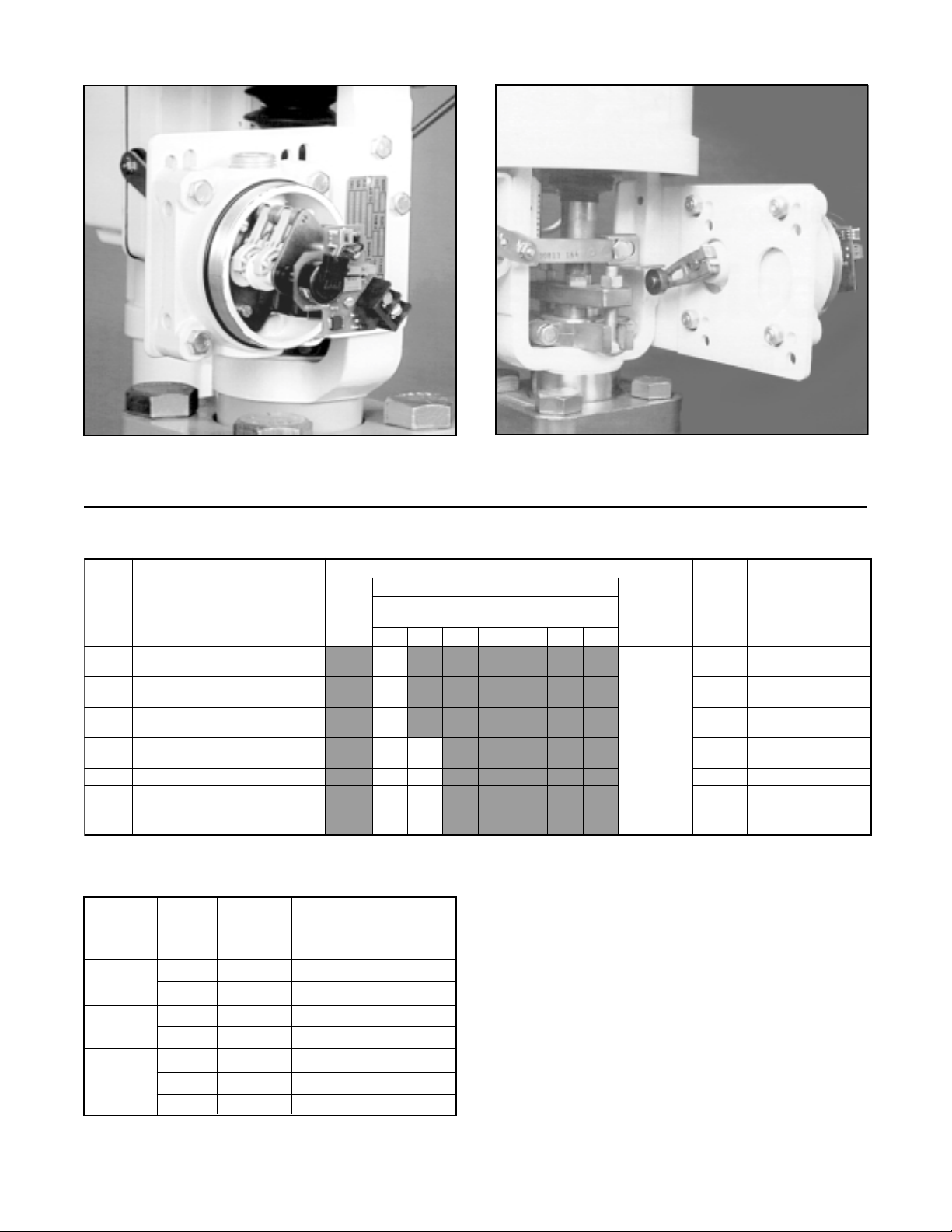
Figure 1: Linear Application – Front View
(cover removed)
Table I: Model Configuration
ledoMnoitpircseD
2HT
ST2H
XT rettimsnartgolanA
2AT
2A sehctiwsTDPSowT
4A sehctiwsTDPSruoF
ST2A
sehctiwsTDPSdelaesyllacitem
TDPSdelaesyllacitemrehowT
hctiwslanimrethtiwsehctiws
owthtiwrettimsnartgolanA
sehctiwsTDPS
htiwsehctiwsTDPSowT
pirtslanimret
AMEN
4
-rehowthtiwrettimsnarTgolanA
2&1 )puorG(
ABCDEFG
Figure 2: Linear Application – Rear View
(cover removed)
aerAlacirtcelE
foorPnoisolpxE
noisiviDIssalC
2&1 )puorG(
noisiviDIIssalC
CELENEC
lavorppA
gnidneP
gnitaR
LUseYgnoL
LUseYgnoL
ASC/LUoNtrohS
LUoNgnoL
LUoNtrohS
LUoNgnoL
LUoNgnoL
delaeS
sehctiwS
gnisuoH
eziS
Table II: Linear Mounting Information
Actuator Valve Spud Kit Hole
Size Stroke Size No.* Set
(sq. in.) (inch) (inch) (Mounting)
25 0.5-1.0 2.00 37434 bottom of slot
1.5 2.00 37434 top of slot
50 0.5-2.5 2.62 37345 bottom holes
3.0 2.62 37345 top holes
100 1.0-3.5 2.62/2.88 37436 bottom holes
& larger 4.0 3.38 37630 top holes
4.0 4.75 71636 top holes
*Kit includes: bracket, arm, trip lever or stem clamp with trip lever
nuts and bolts.
4. Mount Position Pac to the bracket using the mounting holes as specified in Table II: Insert the lever
onto the switch shaft. On larger actuators (size 50
and larger) that use the adjustable lever arm, adjust
the length so that the center of the roller rests on the
center of the tripper bracket. To preload the Position
Pac’s restoring spring, be certain the control valve is
in its minimum signal position. Loosen the lever arm
clamp screw with a 0.14-inch ( 9/64) hex wrench,
allowing the arm to turn on the shaft. While holding
the arm in contact with the bottom of the tripper
bracket and using a slotted screwdriver to rotate the
switch shaft perform the following (all rotation direction instructions are as viewed from the lever arm
side of the Position Pac):
29-2 Flowserve Corporation, Valtek Control Products, Tel. USA 801 489 8611
Page 3
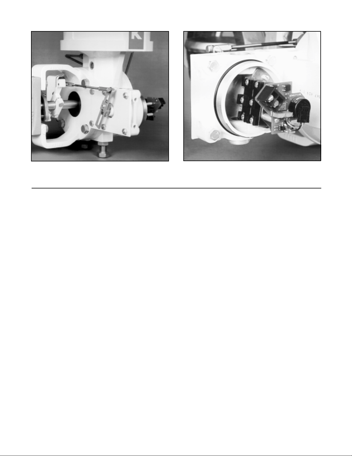
Figure 3: Rotary Application – Rear View
(cover removed; air-to-close valve)
Figure 4: Rotary Application – Front View
(cover removed; air-to-close valve)
For direct-acting, air-to-open actuators, rotate the
shaft counter clockwise as far as it will go, then back
off approximately 5 to 10 degrees. For direct-acting,
air-to- close actuators, rotate the shaft counter clockwise approximately 5 to 10 degrees.
For reverse-acting, air-to-open actuators, rotate the
shaft counter clockwise approximately 5 to 10 degrees. For reverse-acting, air-to-close actuators,
rotate the shaft counter clockwise as far as possible,
then back off approximately 5 to 10 degrees. With the
slot in this position, tighten lever arm clamp screw
tightly (until the teller tab will not move). With this procedure completed, stroke valve to ensure spring is
preloaded throughout the entire valve travel.
5. To make electrical connections, remove the housing
cover.
WARNING: On explosion-proof installations,
disconnect electrical power or be certain the
area is safe from combustible atmospheres before removing the housing cover.
(Refer to the specifications in Table IV for component
electrical ratings.) Attach transmitter signal wiring to
the transmitter terminal block, using caution to attach
the positive and negative wires to the appropriate
terminal.
CAUTION: Do not apply a voltage greater than 40
volts to the transmitter terminals or the circuit
will be damaged.
Attach limit switch wiring to the ‘COMM’ (common)
and either ‘NC’ (normally closed) or ‘NO’ (normally
open) terminals according to the needed signal.
6. To adjust the limit switches and/or position transmitter, remove the housing cover and refer to the
bration
WARNING: On explosion-proof installations,
disconnect electrical power or be certain the
area is safe from combustible atmospheres before removing the housing cover.
7. Replace the housing cover.
8. Reinstall the name plate to the mounting bracket.
section in this document.
Cali-
NOTE: Name plate reinstallation is important for
valve identification/servicing purposes.
Valtek Rotary Actuators
To install Position Pac on Valtek rotary actuators, refer
to Figures 3 and 4, and proceed as follows:
1. Mount the bracket to the mounting pad on the backside of the actuator using two 0.31-inch (5/16) mounting bolts.
2. Mount the Position Pac to the bracket using four
0.31-inch (5/16) mounting bolts and nuts.
3. Loosely mount the trip lever to the valve shaft within
the yoke.
4. Attach the switch lever to the Position Pac shaft.
5. Connect the linkage assembly to both levers as
shown in Figure 3.
6. Measure the approximate radius of the trip lever from
the center of the valve shaft to the linkage assembly
connection (not the end of the lever). Next, adjust
the switch lever to approximately the same radius
and tighten.
Flowserve Corporation, Valtek Control Products, Tel. USA 801 489 8611
29-3
Page 4

Table III: Rotary Mounting Kits
Actuator Valve Shaft
Size Diameter Kit No.*
(sq. in.) (inches)
25 0.62 97556
25 0.75 97557
25 0.88 97558
50 0.62 97559
50 0.75 97560
50 0.88 97561
50 1.12 97562
100 0.88 97563
100 1.12 97564
100 1.50 97565
100 1.75 97566
*Kit includes: bracket, trip lever, switch lever, linkage assembly,
nuts and bolts.
7. With the actuator at its minimum signal position,
slide the trip lever along the shaft until the linkage
assembly is parallel to the mounting bracket. At the
same time, rotate the trip lever until it is at a 45degree angle to the mounting bracket and pointing
toward the top yoke bolt closest to the Position Pac.
Tighten the trip lever on the shaft in this position.
8. Adjust the linkage assembly until the switch lever is
approximately the same angle as the trip lever and
the linkage assembly is horizontal. To preload the
Position Pac's restoring spring (used to remove
backlash in the linkage), be certain the actuator is in
its minimum signal position and perform the following using a slotted screw driver to rotate the switch
shaft (all rotation direction instructions are as viewed
from the lever arm side of the Position Pac):
For direct-acting, air-to-open actuators, rotate the
shaft counter clockwise as far as it will go, then back
off approximately 5 to 10 degrees. For direct-acting,
air-to-close actuators, rotate the shaft clockwise
approximately 5 degrees.
For reverse-acting, air-to-open actuators, rotate the
shaft clockwise approximately 5 degrees. For reverse-acting, air-to-close actuators, rotate the shaft
counter clockwise as far as possible, then back off
approximately 5 to 10 degrees.
With the slot in this position, tighten the lever arm
clamp screw tightly (until the teller tab will not move).
9. If possible, stroke the valve; the linkage assembly
should travel back and forth remaining horizontal.
10.To make electrical connections, remove the housing cover. (Refer to the specifications in Table IV for
the component electrical ratings.) Attach the transmitter signal wiring to the transmitter terminal block,
using caution to attach the positive and negative
wires to the appropriate terminal. Attach the limit
switch signal wiring to ‘COMM’ (common) and either
‘NC’ (normally closed) or ‘NO’ (normally open) terminals according to the needed signal.
WARNING: On explosion-proof installations,
disconnect electrical power or be certain the
area is safe from combustible atmospheres before removing the housing cover.
11.To adjust the limit switches and/or the position transmitter, remove the housing cover and refer to the
Calibration
12.Replace the housing cover.
section in this document.
CALIBRATION
When a Position Pac is installed in the field or a factory
installed unit needs to have output signal adjustments
made, refer to Figure 5 and proceed as follows:
Limit Switch
Position Pac limit switches are adjusted at the factory
before shipment and should not require on-site adjustment. However, if the mechanical lever has shifted
position, the unit may need readjustment. To readjust
the limit switch, proceed as follows:
CAUTION: If the valve cannot be stroked without
disturbing the process fluid, bypassing or removing the valve from the line may be necessary before
calibrating the Position Pac.
WARNING: Prior to removing the valve from the line,
depressurize the line to atmospheric pressure, drain
all process fluid and, if caustic or hazardous material are present, decontaminate the valve. Failure to
do so can cause serious injury.
1. Stroke the valve to the closed position.
WARNING: Keep hands, hair, clothing, etc. away
from moving parts when operating the valve.
Failure to do so can cause serious injury.
2. Remove the housing cover from the Position Pac.
WARNING: On explosion-proof installations,
disconnect electrical power or be certain the
area is safe from combustible atmospheres before removing the housing cover.
3. Lift the appropriate cam follower lever. Move the
cam wheel axially to disengage the teeth on the
wheel from the teeth on the shaft disc.
4. Turn the cam wheel to the desired position. Each
notch on the cam wheel represents an operating
point change of 70 20'.
5. When the cam wheel has been rotated to the desired
location, slide the cam wheel to engage with the
mating shaft disc. (For finer adjustment, use the
setscrew in the cam follower.)
6. Release the cam follower lever.
7. Cycle the valve and check for proper adjustment.
Readjust if necessary.
8. Replace the housing cover.
29-4 Flowserve Corporation, Valtek Control Products, Tel. USA 801 489 8611
Page 5

Transmitter
terms
block
Limit switch
wiring terminal
Limit switch
adjustment cams
(not shown)
Transmitter span
adjusting screw
(pot)
Transmitter zero
Adjusting Screw
(pot)
Figure 5: Calibration Points
Position Transmitter
1. Remove the housing cover from the Position Pac.
WARNING: On explosion-proof installations,
disconnect electrical power or be certain the
area is safe from combustible atmospheres before removing the housing cover.
2. Wire the Position Pac transmitter in series with a
12.5-40 VDC power supply and a milliamp meter.
NOTE: Instructions within parenthesis ( ) refer to
older Position Pac models characterized by a white
label.
CAUTION: Do not apply a voltage greater than 40
volts to transmitter terminals or the circuit will be
damaged.
3. Be certain the CW/CCW Switch located next to the
potentiometer (Direct/Reverse Switch located next
to the wire terminal block) is set to provide the desired output signal action. In the CW (DIR) position,
a clockwise rotation of the Position Pac shaft will
cause the output signal to increase. In the CCW
(REV) position, a counterclockwise stem rotation
causes the signal to increase.
4. Stroke the valve to the closed position.
WARNING: Keep hands, hair, clothing, etc. away
from moving parts when operating the valve.
Failure to do so can cause serious injury.
Clockwise/counterclockwise switch
5. Referring to Figure 5, adjust the ZERO adjusting
screw with a small, straight end screw driver, until the
meter reads 4 mA DC.
6. Stroke the valve to the open position.
7. Adjust the SPAN adjusting screw until the meter
reads 20 mA DC.
8. Stroke valve to the closed position and recheck the
meter for 4 mA DC. Some readjusting of the calibration may be required. Repeat steps 4-8 until satisfied.
9. If calibration is unsuccessful after following this procedure, one of two problems may exist: (a) The orientation of the Position Pac stem may need to be
adjusted. (b) The ZERO and SPAN potentiometers
may be adjusted out of range.
NOTE: The electrical travel of the potentiometer is
340 (150) degrees. To operate properly, the poten-
tiometer wiper must stay within the center 185 degrees of its 340 degree electrical range during the full
stroke of the valve.
9a.To adjust, stroke the valve to its middle position.
Loosen the potentiometer collar nut. While measuring the voltage between pins 1 and 2 on the back of
the potentiometer, rotate the potentiometer until the
voltage is between 0.55 and 0.65 volts. Retighten
the potentiometer being careful to keep the potentiometer oriented in the same position.
Flowserve Corporation, Valtek Control Products, Tel. USA 801 489 8611
29-5
Page 6

9b.Set the ZERO and SPAN potentiometers to their
approximate middle position. This is accomplished
by first turning each potentiometer clockwise 25
turns or until a ‘click’ is either felt or heard. Then turn
each potentiometer counterclockwise approximately 12 complete turns. Repeat steps 2 through 8
to complete calibration.
10.Replace the housing cover.
REVERSING POSITION TRANSMITTER
SIGNAL
The following instructions should be used when the signal being transmitted from the position transmitter is
either incorrect or needs to be reversed. Refer to
Figure 5.
Figure 6: Wiring Diagram
1500
L
Max. Load Resistance, R (Ω)
R = V - 12.5V
1250
1000
750
500
250
L max PS
20 mA
Operating
Region
0
0 10 20 30 40 50 60
Power Supply Voltage, V (volts)
PS
Figure 7: Power Supply Requirements
NOTE: Instructions within parenthesis ( ) refer to older
Position Pac models characterized by a white label.
1. Remove the housing cover.
WARNING: On explosion-proof installations,
disconnect electrical power or be certain the
area is safe from combustible atmospheres before removing the housing cover.
2. Locate the switch next to the position transmitter’s
wiring terminal. Move switch to the opposite position, CCW or CW (DIR or REV). Repeat steps 3-9 in
the
Calibration
section for the position transmitter.
NOTE: The SPAN potentiometer will generally not
need readjustment.
3. Replace the housing cover.
Table IV: Specifications
Analog Output
Power Supply Range 12.5 to 40 VDC (24V DC typical)
Maximum Load Maximum Resistance (ohms) =
Resistance Supply Voltage - 12.5
(see Figure 3)
Current Signal Output 4-20 mA
Span Adjustable from 5° to 100° of angular
Null 4 mA position may be set at any angular
Linearity ±1.0% full-scale*
Repeatability ±0.25% full-scale
Hysteresis ±1.0% full-scale
Operating -40O to 185O F (-40O to 85O C)
Temperature Range
Ambient Temperature For a 100O F (38O C) change in ambient
Range temperature, maximum zero shift is
Power Supply Output signal changes less than
rotation
position
±0.4% full scale, maximum span
shift is ±0.7% full scale
0.05% when supply voltage is varied
between 12.5 and 40 volts dc
Limit Switches
(SPDT) 20 amps, 125, 250, 480 VAC, ind. and
UL/CSA Rating (L23) res. 1 Hp. 125 VAC; 2 Hp, 250 VAC, 0.5
amp. 125 VDC; 0.25 amp, 250 VDC res.
Mechanical
Input motion ±105O from the center; spring
* Linearity is ±1.0% for 90O rotary shaft input. When mounted to
linear travel valves, linearity is dependent on linkage design and
stroke length. Typical linearity is ±1.5% full-scale on Valtek Mark
One control valves.
loaded to return to the center
0.02
29-6 Flowserve Corporation, Valtek Control Products, Tel. USA 801 489 8611
Page 7

Rotary
Short Housing Long Housing
4.00
102
1.26 dia. max.
32
0.72
18
3.15
80
2.00
51
0.33 dia. thru (4)
8
1.57
40
0.25
Front Mounting
0.49
12
0.75
19
0.88
22
0.37
9
2.38 typ
60
0.80
20
1.00
25
4.09 max.
104
3.78 max.
96
3.86 dia.
98
0.75 - 14 NPT
(5 full threads min.) (2)
Eight side mounting holes
can be tapped 5/16 - 18-inch
Lever Actuators
6
4.04
103
0.74
19
0.83
21
0.39
10
1.50
38
0.88
22
0.37
9
Adjust
1.50 - 3.70
38 - 94
0.72
18
0.29 dia.
7
0.80
20
1.00
5.71 max.
145
3.78 max.
133
3.82 dia.
97
0.75 - 14 NPT
1.00
25
0.57
0.50
14
13
25
0.27
7
0.16
4
0.09
(5 full threads min.) (2)
0.16
4
0.31
8
2
Figure 8: Dimensions
Flowserve Corporation, Valtek Control Products, Tel. USA 801 489 8611
29-7
Page 8

Troubleshooting
Failure Probable Cause Corrective Action
Operation erratic 1. Loose bracket bolting 1. Tighten bolting bracket to yoke leg or transfer
and inconsistent case: readjust position transmitter and switches
2. Loose Position Pac mounting 2. Tighten mounting screws, readjust position
screws transmitter and switches
3. Loose tripper bracket 3. Tighten tripper bracket or extended spline
(linear actuator) or extended connector
spline connector (rotary
actuator)
4. Internal or electrical 4a. Ensure that terminal block connections are
malfunction tight
4b. Check for foreign material in contact with printed
circuit board or components
4c. Check for components or wires broken loose
from printed circuit board
4d. Check that the switch is fully set in desired
position
Indicating 1. Incorrect adjustment 1. Refer to
incorrect position
2. Internal or electrical 2a. Ensure that terminal block connections are
tight
2b. Check for foreign material in contact with printed
circuit board or components
2c. Check for components or wires broken loose
from printed circuit board
2d. Check that the switch is fully set in desired
position
Calibration
section, step 9
Flowserve Corporation has established industry leadership in the design and manufacture of its products. When properly selected, this Flowserve product is designed to perform its
intended function safely during its useful life. However, the purchaser or user of Flowserve products should be aware that Flowserve products might be used in numerous applications
under a wide variety of industrial service conditions. Although Flowserve can (and often does) provide general guidelines, it cannot provide specific data and warnings for all possible
applications. The purchaser/user must therefore assume the ultimate responsibility for the proper sizing and selection, installation, operation and maintenance of Flowserve products.
The purchaser/user should read and understand the Installation Operation Maintenance (IOM) instructions included with the product, and train its employees and contractors in the safe
use of Flowserve products in connection with the specific application.
While the information and specifications presented in this literature are believed to be accurate, they are supplied for informative purposes only and should not be considered certified or
as a guarantee of satisfactory results by reliance thereon. Nothing contained herein is to be construed as a warranty or guarantee, express or implied, regarding any matter with respect
to this product. Because Flowserve is continually improving and upgrading its product design, the specifications, dimensions and information contained herein are subject to change
without notice. Should any question arise concerning these provisions, the purchaser/user should contact Flowserve Corporation at any of its worldwide operations or offices.
For more information, contact:
Flowserve and Valtek are registered trademarks of Flowserve Corporation.
29-8 Flowserve Corporation, Valtek Control Products, Tel. USA 801 489 8611
FCD VLAIM029-04 © 2000 Flowserve Corporation. Flowserve Corporation, Valtek Control Products, Tel. USA 801 489 8611
For more information about Flowserve, contact www.flowserve.com or call USA 972 443 6500
Regional Headquarters
1350 N. Mt. Springs Prkwy.
Springville, UT 84663
Phone 801 489 8611
Facsimile 801 489 3719
12 Tuas Avenue 20
Republic of Signapore 638824
Phone (65) 862 3332
Facsimile (65) 862 4940
12, av. du Québec, B.P. 645
91965, Courtaboeuf Cedex,
France
Phone (33 1) 60 92 32 51
Facsimile (33 1) 60 92 32 99
Quick Response Centers
5114 Railroad Street
Deer Park, TX 77536 USA
Phone 281 479 9500
Facsimile 281 479 8511
104 Chelsea Parkway
Boothwyn, PA 19061 USA
Phone 610 497 8600
Facsimile 610 497 6680
1300 Parkway View Drive
Pittsburgh, PA 15205 USA
Phone 412 787 8803
Facsimile 412 787 1944
 Loading...