

Page 1
®
User Instructions - MaxFlo 3 - VLEEIM7001-03 07.07
USER INSTRUCTIONS
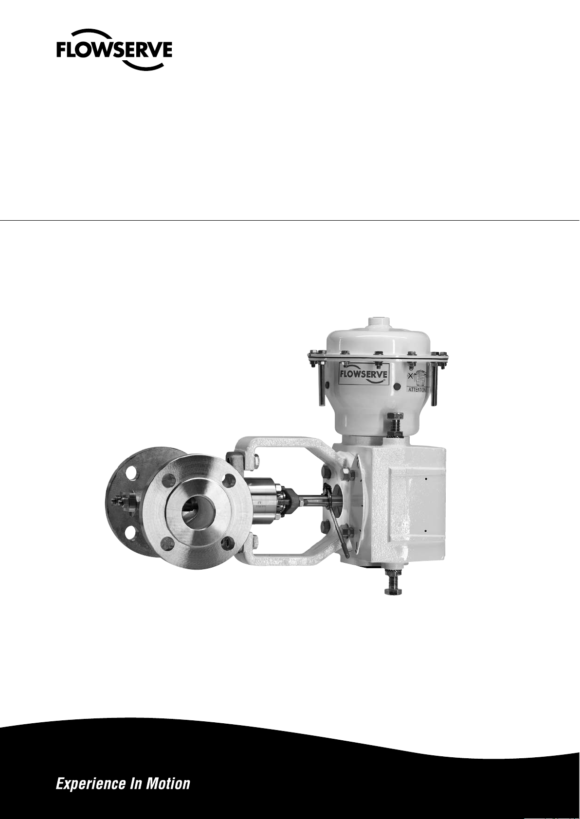
Valtek MaxFlo 3
Control Valves
Installation
Operation
Maintenance
1
Page 2

®
User Instructions - MaxFlo 3 - VLEEIM7001-03 07.07
SUMMARY
1 GENERAL INFORMATION
2 INSTALLATION
3 QUICK-CHECK
4 PREVENTATIVE MAINTENANCE
5 VALVE DISASSEMBLY
6 BODY REASSEMBLY
7 SEAT REPLACEMENT
8 ACTUATOR REMOUNTING
9 PRINCIPLES OF SHAFT ANTI-BLOWOUT SYSTEM
10 MOUNTING ORIENTATION– AIR-TO-OPEN CONFIGURATION
11 MOUNTING ORIENTATION – AIR-TO-CLOSE CONFIGURATION
12 TROUBLESHOOTING
2
Page 3
®
User Instructions - MaxFlo 3 - VLEEIM7001-03 07.07
STOP!
STOP!
1 GENERAL INFORMATION
1.1 Use
The following instructions are designed to assist in
the unpacking, installation, and maintenance as required for Flowserve products. Product users and
maintenance personnel should thoroughly review this
manual prior to installing, operating, or performing
any maintenance.
In most cases, Flowserve accessories, actuators and
valves are designed for specific applications (e.g. with
regard to medium, pressure and temperature). For this
reason, they should not be used in other applications
without first contacting the manufacturer.
1.2 Terms related to safety
The terms DANGER, WARNING, CAUTION, NOTE are
used in this document to highlight particular dangers
and/or to provide additional information on points
which may not be clearly obvious.
DANGER: Indicates that death, severe personal injury
and/or substantial property damage will occur if proper precautions are not taken.
WARNING: Indicates that danger of death or severe
personal injury and/or property damage can occur if
proper precautions are not taken.
CAUTION: Indicates that minor personal injury and/or
serious damage to property can occur if the appropriate precautions are not taken.
NOTE: Indicates and provides additional technical in-
formation which may not be obvious, even to qualified
personnel.
Compliance with other notes, which may not be partic-
ularly emphasized, with regard to transport, assembly,
operation and maintenance and with regard to technical documentation (e.g. in the operating instructions,
product documentation, or on the product itself) is
essential, in order to avoid faults, which can directly
or indirectly cause severe personal injury or property
damage..
2 INSTALLATION
2.1 Before installing the valve, clean the pipeline of all con
tamination, carbon deposits, welding chips, and other
foreign material. Carefully clean gasket surfaces to ensure a tight seal. Pipelines must be correctly aligned to
ensure that the valve is not fitted under tension.
2.2 Check the direction of fluid flow to ensure that the valve
is correctly installed. Flow direction is indicated by the
arrow attached to the body. All installation orientations
for fitting the valve into the pipeline are defined at the
end of this manual.
DANGER: To avoid serious injury, keep hands, hair,
clothing, etc away from the plug and seat when the
valve is working.
2.3 Connect the air supply and instrument signal lines.
Throttling control valves are equipped with a valve
positioner. Connections are marked for the air supply
and the instrument signal. Check that the actuator and
positioner can withstand the maximum air supply from
the network. The required air supply is indicated on a
sticker located on the actuator. An air regulator will be
necessary in certain cases in order to limit the supply
pressure. A filter is recommended unless the air supplied is exceptionally clean and dry (air quality without
humidity, oil, or dust as per IEC 770 and ISA-7.0.01).
All connections must be completely tight.
2.4 Use the bolts indicated in table I for installing the valve
in the pipeline, and then tighten alternately according
to good practice. The user must in all cases confirm
the capacity of the bolts to ensure a sufficiently tight
gasket seal for the expected service conditions.
-
1.3 Protective clothing
Flowserve products are often used in problematic ap-
plications (e.g. under extremely high pressures with
dangerous, toxic or corrosive mediums). When performng service, inspection, or repair operations, always ensure that the valve and the actuator are depressurized and that the valve has been cleaned, and
that it is free of harmful substances. In such cases, pay
particular attention to personal protection (e.g. protective clothing, gloves, glasses etc).
1.4 Qualified personnel
Qualified personnel are people who on account of their
education, experience, training, and knowledge of relevant standards, specifications, accident prevention,
and operating conditions have been authorized by
those responsible for the safety of the plant to perform
the necessary work, and recognize and avoid possible
dangers.
3
Page 4
®
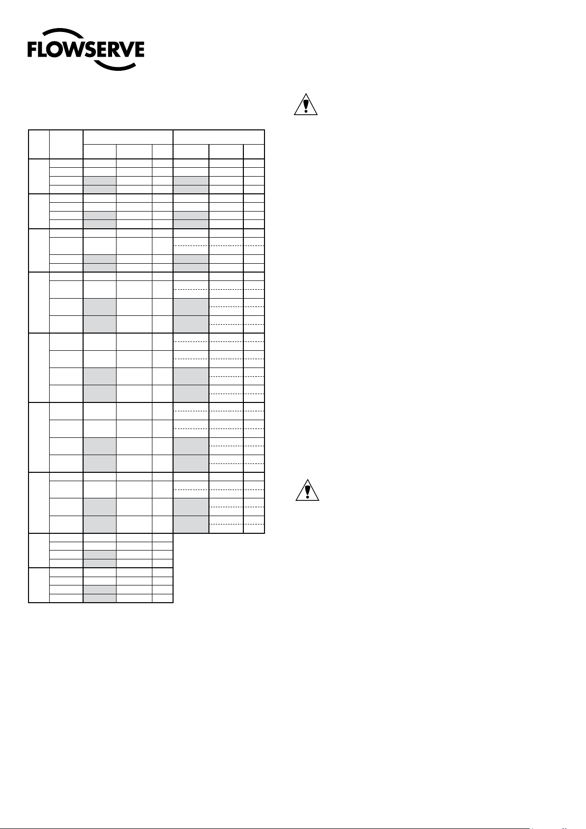
Table I: Line Flange Bolting Specifications
Size
Nominal
vanne
Pressure /
Rating
ANSI 150 1/2 X 2.62 M12 X 65
ANSI 300 5/8 X 3.12 M16 X 80 8 5/8 X 6.88 M16 X 175 4
DN25
1"
PN 16
PN 40 M12 X 70 8 M12 X 175 4
ANSI 150 1/2 X 2.88 M12 X 70
ANSI 300 3/4 X 3.62 M20 X 95 8 3/4 X 8.38 M20 X 215 4
DN40
1½"
PN 16
PN 40 M16 X 80 8 M16 X 200 4
ANSI 150 5/8 X 3.25 M16 X 85
ANSI 300 5/8 X 3.5 M16 X 90 16
DN50
2"
PN 16
PN 40 M16 X 85 8 M16 X 215 4
ANSI 150 5/8 X 3.62 M16 X 95
ANSI 300 3/4 X 4.25 M20 X 110 16
DN80
3"
PN 16
PN 40 M16 X 95 16
ANSI 150 5/8 X 3.62 M16 X 95 16
ANSI 300 3/4 X 4.5 M20 X 115
DN100
4"
PN 16
PN 40 M20 X 100 16
ANSI 150
ANSI 300 3/4 X 4.88 M20 X 125 24
DN150
6"
PN 16
PN 40 M24 X 115 16
ANSI 150 3/4 X 4.25 M20 X 110 16 3/4 X 4.25 M20 X 360
ANSI 300 7/8 X 5.5 M22 X 140 24
DN200
8"
PN 16
PN 40 M27 X 135 24
ANSI 150 7/8 X 4.62 M22 X 120 24
ANSI 300 1 X 6.25 M24 X 155 32
DN250
10"
PN 16
PN 40 M30 X 150 24
ANSI 150
ANSI 300 1 1/8 X 6.75 M27 X 170 32
DN300
12"
PN 16
PN 40 M30 X 160 32
MaxFlo 3 flanged
Size x Length
Inches Metric
M12 X 70 8 M12 X 175 4
M16 X 80 8 M16 X 200 4
M16 X 85 8 M16 X 215 4
M16 X 85 16
M16 X 85 16
3/4 X 3.75 M20 X 105 16
M20 X 100 16
M20 X 100 24
M24 X 110 24
7/8 X 4.75 M22 X 120 24
M24 X 115 24
Qty /
vanne
8 1/2 X 6.75 M12 X 170 4
8 1/2 X 7.50 M12 X 190 4
8 5/8 X 8.38 M16 X 215 4
8 5/8 X 10.5 M16 X 265 4
16
MaxFlo3 flangeless
Size x Length
Inches Metric
5/8 X 3.50 M16 X 90 4
5/8 X 8.50 M16 X 220 6
3/4 X 4.25 M20 X 110
3/4 X 11.00 M20 X 280
M16 X 85 6
M16 X 255
M16 X 95 6
M16 X 265
5/8 X 3.62 M16 X 95
5/8 X 11.5 M16 X 295
3/4 X 4.5 M20 X 115 4
3/4 X 12.25 M20 X 315
M16 X 85 6
M16 X 285
M20 X 100 6
M20 X 300
3/4 X 3.75 M20 X 105 4
3/4 X 13.25 M20 X 340
3/4 X 4.88 M20 X 125 8
3/4 X 14.00 M20 X 360
M20 X 100 4
M20 X 335
M24 X 115 4
M24 X 350
7/8 X 5.5 M22 X 140 4
7/8 X 15.19 M22 X 390 10
M20 X 100 8
M20 X 350
M27 X 135 8
M27 X 385
Qty /
vanne
4
6
5
5
4
6
6
5
5
6
8
6
6
8
8
8
3 QUICK-CHECK
Before commissioning, check the control valve by fol
lowing these steps:
3.1 Check for full stroke by varying the instrument signal
settings appropriately. Observe the plug position indicator located on the actuator or the positioner. The
plug should change position with a smooth turning
movement.
3.2 Check all air connections for leaks. Tighten or replace
any leaking lines.
3.3 Check packing box bolting for proper tightness.
User Instructions - MaxFlo 3 - VLEEIM7001-03 07.07
CAUTION: Do not overtighten packing. This can cause
excessive packing wear and high stem friction that
may impede shaft movement. After the valve has been
in service for a short period, recheck the packing-box
nuts. If the packing-box leaks, tighten the nuts just
enough to stop the leak.
3.4 Make sure the valve fails in the correct direction in case
of air failure. This is done by positioning the valve at
mid-stroke and turning off the air supply and observing the failure direction. If the action is incorrect, see
the section “Reversing the Air-action” in the instructions of the installation, operation and maintenance
manual of the appropriate actuator.
4 PREVENTATIVE MAINTENANCE
At least once every six months, check for proper oper-
ation by following the preventative maintenance steps
outlined below. These steps may be performed while
the valve is in-line and without interrupting service. If
an internal problem is suspected, refer to section “Disassembling the Valve”.
4.1 Look for signs of gasket leakage through the end
flanges and bonnet. If necessary, re-torque flange,
bonnet and post bolting.
4.2 Examine the valve for damage caused by corrosive
fumes or process drippings.
4.3 Clean the valve and repaint areas of severe oxidation.
4.4 Check the packing-box for proper tightness. If there is
a persistent leak, change the packing after referring to
section “Valve Disassembly and Body Reassembling”.
CAUTION: Do not overtighten packing. This can cause
excessive packing wear and high friction that may impede shaft movement.
4.5 If the valve is equipped with a lubricator, add lubricant
if necessary.
4.6 If possible, stroke the valve and check for smooth,
full-stroke operation. Unsteady shaft movement may
indicate an internal valve problem.
4.7 Check the calibration of the positioner. For further
preventative maintenance, see the instructions in the
installation, operation and maintenance manual for the
-
applicable positioner.
4.8 Ensure all accessories, brackets and bolting are securely fastened.
4.9 If possible, remove air supply and observe actuator for
correct fail-safe action.
4.10 Check the actuator and all air connections for leaks.
4.11 If an air filter is supplied, check and replace the cartridge if necessary.
4
Page 5
®
User Instructions - MaxFlo 3 - VLEEIM7001-03 07.07
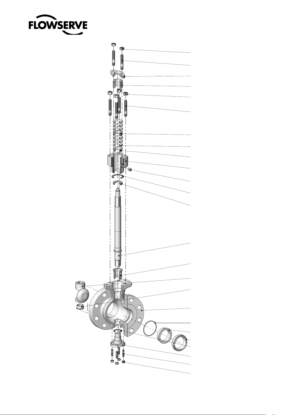
Item 117 Packing box nuts
Item 109 Packing box studs
Item 80 Gland flange
Item 87 Packing follower
Item 114 Bonnet nuts
Item 108 Bonnet studs
Item 93 Packing spacer
Item 88 Packing set
Item 99 Packing stop
Item 40 Bonnet
Item 42 Purge plug (optional)
Item 58 Bonnet gasket
Item 46 Thrust bearing
Figure 1: MaxFlo 3 valve body assembly
item numbers correspond directly to the valve’s bill of material. Refer
to it for specific part numbers.
Item 51 Shaft
Item 83 Shaft bearing
Item 50 Plug
Item 84 End post bearing
Item 1 Body
Item 23 Shims
Item 20 Seat
Item 30 Seat retainer
Item 61 End post gasket
Item 122 End post
Item 115 End post studs
Item 119 End post nuts
5
Page 6

®
User Instructions - MaxFlo 3 - VLEEIM7001-03 07.07
STOP!
5 VALVE DISASSEMBLY
WARNING: To carry out this operation, it is essential to
disconnect the valve from the pipework. Depressurize
line to atmospheric pressure and drain all fluids before
working on the valve. Failure to do so can cause serious injury. Remove the valve from the pipeline.
Refer to figure 1 to find parts according to the item
numbers.
5.1 Remove the actuator from the body by separating the actuator at the yoke. Refer to the installation, operation and
maintenance manual for the corresponding actuator.
5.2 Remove the four bonnet nuts (item 114).
5.3 Remove the packing nuts and gland flange (item 80)
5.4 Carefully pull the shaft (item 51) out of the body. The
bonnet, thrust bearing, packing stop and packing will
all slide out of the body bore as an assembly.
5.5 Remove the end post nuts (item 119) and carefully remove the end post (item 122) from the body.
NOTE: At this point in the disassembly operation, the
plug is inside the valve body and is only supported by the
end post. When removing the end post, support the plug
so it does not drop into the bottom of the valve body.
5.6 Remove the plug from the body. See figure 2a.
5.7 Loosen the packing-box nuts (item 117) and remove the
shaft from the bonnet by sliding it out slowly. The thrust
bearing (item 46) and the shaft stop spacer (item 47, only
for sizes 10 to 12”) can now be removed from the shaft.
5.8 Remove the packing follower (item 87) as well as the
packing (item 88), spacers (item 93) and the packing
stop (item 99).
5.9 Remove the bonnet gasket (item 58) and end post
gasket (item 61). Clean all bearing and seal surfaces.
5.10 Remove the shaft bearing (item 83) from the valve
body. Use a suitable dowel to push the bearing out if
necessary. Be careful not to damage the bearing.
5.11 Unscrew the seat (item 30) using the appropriate tool
(see Table IV) and remove the seat (item 20) as well as
the adjustment shims (item 23).
6 BODY REASSEMBLY
NOTE: Lubricate all threads, bearings and the shaft
shoulder with a boron nitride paste (e.g. Molydal
NB1200) . Place the valve body in a vice and clamp
securely in a vertical position.
6.1 Always use new packing and gaskets when reassembling a valve.
6.2 Make sure that the shaft, bonnet bore and gasket surfaces in the body have been thoroughly cleaned (these
are sealing surfaces and it is important to remove any
contamination before reassembly).
6.3 Make sure that all bearing surfaces have been
cleaned.
6.4 Install all end post (item 115) and bonnet (item 108)
studs.
6.5 Insert the plug in the body as shown in figure 2b.
NOTE: The end post bearing (item 84) is pressed into
the plug.
6.6 Place the end post gasket (item 61) on the end post
(item 122). Insert the end post into the small flanged
port in the end of the body. As the end post is inserted,
locate the plug (item 50) so the end post will insert
into the end post bearing located in the plug.
NOTE: For valves 3’’ and larger, insert the end post
with the milled faces parallel to the flanges of the valve
body.
6.7 Tighten the end post nuts to finger tight.
6.8 Insert the shaft bearing (item 83) into the body until the
shoulder on the bearing contacts the step in the valve
body. The bearing will protrude slightly into the body gallery area.
6.9 Place the thrust bearing onto the shaft. Slide it up
to the thrust runner. The shaft thrust bearing will
surround the thrust runner.
NOTE: for sizes 10” and 12”, an end spacer (item 47)
is placed above the thrust bearing.
6.10 Place the bonnet gasket (item 58) on the gasket step
Table II: Nut tightening torques for bonnet and pivot post
Size A193-B8 cl2
M8 10 Nm 14 Nm
M12
M16
37 Nm 41 Nm
53 Nm 59 Nm
A453-Gr660
(Nace)
Figure 2a: Plug Removal
6
inside the body. Gently push the bonnet into the bonnet bore.
NOTE: When installing the bonnet, orient the milled
faces on the bonnet perpendicular to the flanges of the
valve body.
Figure 2b: Plug Installation
Page 7

®
User Instructions - MaxFlo 3 - VLEEIM7001-03 07.07
6.11 Place the packing stop (item 99) into the bonnet,
then install the packing spacer (item 93) and packing
as shown in figure 3.
6.12 Install the packing follower (item 87) and gland flange
(item 80), then tighten the packing nuts to finger
tight.
6.13 Install bonnet nuts and tighten to finger tight.
6.14 Tighten the bonnet and end post nuts evenly. Torque
nuts to the values listed in table II.
6.15 Install the shims (item 23) and seat ring (item 20) as
described in the Seat Replacement section.
6.16 Install the actuator and yoke as described in the installation manual for the corresponding actuator.
6.17 Install the valve into the process line as described in
the installation section.
Standard V-ring Twin V-ring Twin V-ring Vacuum Seal Standard graphite Twin graphite
“Live Loading” system:
- optional for SureGuard / XT
- standard for SafeGuard
“Live Loading” system:
- optional for SureGuard / XT
- standard for SafeGuard
Standard SureGuard
Standard SureGuard XT
Standard SafeGuard
Twin SureGuard
Twin SureGuard XT
Twin SafeGuard
Figure 3: Packing Configurations
Standard SureGuard Firesafe
Standard SureGuard XT Firesafe
Standard SafeGuard Firesafe
Twin SureGuard Firesafe
Twin SureGuard XT Firesafe
Twin SafeGuard Firesafe
7
Page 8

®
7 SEAT REPLACEMENT
STOP!
WARNING: The actuator must be removed from the
valve body prior to replacing the seat ring.
7.1 To replace the seat, see figures 5a and 5b, and proceed
as follows:
7.2 Loosen the packing box nuts.
7.3 Using the appropriate retainer tool (see Table III), remove the seat retainer. (Retainer tools are available
from the factory).
7.4 Remove the seat and any shims that may be installed
under the seat.
7.5 Check both seat and plug surfaces for wear and galling. Replace these parts if necessary.
7.6 Clean seat ring, seat retainer and body threads of old
sealant residue. Clean parts thoroughly.
7.7 To reinstall the seat, place the seat (without shims)
into the valve body. Rotate the plug to 90 degrees
open. Measure dimension “A” as shown in figure 4a.
7.8 Close the plug into the seat and then measure dimension “B” as shown in figure 4b.
User Instructions - MaxFlo 3 - VLEEIM7001-03 07.07
NOTE: For optimum sealing do not over-rotate the plug
into the seat. A very slight under-rotation is recommended. (See figure 5)
7.9 The difference between dimension “A” and “B” represents the total thickness of the adjustment shims to be
added between the seat and the valve body. See table
III to select the necessary shim(s). Regardless of the
valve size, at least one shim must be present.
7.10 Remove the seat and add the appropriate number of
shims. (Flowserve recommends a sealant with a temperature range of –70 to 200°C, type Dow Corning
RTV 736, or a sealant with a graphite base for higher
temperatures or for steam processes.)
7.11 Apply lubricant to the threads of the seat retainer. Replace the seat retainer and tighten manually until it
makes contact with the seat, then loosen it by 1/8 of
a turn. Open and close the valve several times while
tightening the seat retainer manually to position the
seat correctly. Finally, close the valve and tighten the
seat retainer according to the values in table IV.
Parts supplied with the toolkit
for removing the seat retainer
Upon contact with the seat, the horizontal axis of the plug must never be rotated
past the horizontal axis of the valve body.
The plug should rotate into the seat as
close to the horizontal axis as possible.
To increase this lag, reduce the thickness
of the shims, and vice-versa.
Figure 4a: definition of dimension “A” with plug open
A
Figure 4b: definition of dimension “B” with plug closed
B
Figure 4: shimming the seat
8
Page 9

®
User Instructions - MaxFlo 3 - VLEEIM7001-03 07.07
Recommended plug rotation.
Plug slightly under-rotated.
Maximum limit for plug rotation. The plug
should not be rotated further.
Recommended plug rotation
exceeded. Setting should be
avoided.
Figure 5: positioning of plug
Table III: Shim Selection
Thickness of shims available
Valve Size Rounding rule Example Chosen thickness 0.1 mm 0.15 mm 0.2 mm 0.3 mm 0.5 mm
1"
DN25
1.5" to 8"
DN40 – DN200
10" – 12"
DN250 – DN300
to 0.05 mm
to 0.1 mm
A - B - 0.3
rounded to 0.5mm
A – B = 0.27 mm
rounded to 0.25 mm
A – B = 0.27 mm
rounded to 0.2 mm
A – B = 0.9 mm
A – B – 0.3 mm = 0.6 mm
0.1 mm
0.15 mm
X X X X
0.2 mm X X X X
0.5 mm X X X
Table IV: Seat Retainer Removal Tools and Required Torque Values
Face-to-Face
Valve size
1"
DN 25
1.5"
DN 40
2"
DN 50
3"
DN 80
4"
DN 100
6"
DN 150
8"
DN 200
10"
DN 250
12"
DN 300
ANSI/ISA-75.08.02, EN 558.1/2 series 36,
IEC 60534-3-2, DIN 3202 F1,
EN 558-1/2 series 1
Part number: 183224.999.000
Torque: 41 ft-lbs / 55 Nm
Part number: 183225.999.000
Torque: 103 ft-lbs / 140 Nm
Part number: 183226.999.000
Torque: 155 ft-lbs / 210 Nm
Part number: 183227.999.000
Torque: 406 ft-lbs / 550 Nm
Part number: 183228.999.000
Torque: 428 ft-lbs / 580 Nm
Part number: 183229.999.000
Torque: 959 ft-lbs / 1300 Nm
Part number: 183230.999.000
Torque: 701 ft-lbs / 950 Nm
Part number: 183231.999.000
Torque: 553 ft-lbs / 750 Nm
Part number: 183232.999.000
Torque: 752 ft-lbs / 1020 Nm
ANSI/ISA-75.08.0,
EN 558-1/2 series 37-38,
IEC 60534-3-1
Part number: 183229.999.000
Torque: 959 ft-lbs / 1300 Nm
Part number: 183230.999.000
Torque: 701 ft-lbs / 950 Nm
Part number: 183231.999.000
Torque: 553 ft-lbs / 750 Nm
9
Page 10

®
User Instructions - MaxFlo 3 - VLEEIM7001-03 07.07
8 ACTUATOR REMOUNTING
NOTE: The MaxFlo 3 valve opens in a clockwise direc-
tion when looking down the valve shaft.
8.1 When remounting the actuator to the valve, refer to the
appropriate actuator manual.
9. PRINCIPLES OF SHAFT ANTI-BLOWOUT SYSTEM
NOTE: The actuator stroke stops must be adjusted
correctly to avoid any over-rotation of the plug stroke.
Poor adjustment can cause damage to the valve. Pay
special attention to the adjustment of the closing stop
when the valve has a soft seat.
8.2 Install the valve in the pipeline as indicated in the “Installation” section according to the orientation recommendations given at the end of the manual.
Figure 6a: old design
NOTE: The MaxFlo 3 valve has been significantly im-
proved, with even greater safety for the anti-blowout
system (see figure 6).
The diameter of the shaft shoulder exceeds the di-
ameter of the bonnet bore. Even if the thrust bearing
(item 46) is not installed during reassembly, the shaft
cannot pass through the bonnet.
10
Figure 6b: new design
It is possible to upgrade from the old design (prior to
mid-2006) by changing the bonnet (40) and the packing stop (99).
To order the correct replacement parts, contact your
Flowserve representative with the serial numbers
of the valves requiring the upgrade.
Page 11

®
User Instructions - MaxFlo 3 - VLEEIM7001-03 07.07
LEFT
RIGHT
AIR OPENS
TOP
FLUID
LEFT
RIGHT
AIR OPENS
TOP
FLUID
LEFT
RIGHT
AIR OPENS
TOP
FLUID
LEFT
RIGHT
AIR OPENS
TOP
FLUID
LEFT
RIGHT
AIR OPENS
TOP
FLUID
RIGHT
LEFT
AIR OPENS
TOP
FLUID
LEFT
RIGHT
TOP
AIR OPENS
FLUID
LEFT
RIGHT
FLUID
AIR OPENS
TOP
10. PIPELINE MOUNTING ORIENTATIONS – AIR-TO-OPEN CONFIGURATION
Shaft downstream – Flow to open
VIEW
VIEW
Shaft upstream – Flow to close
VIEW
VIEW
-
ing
Horizontal Flow –
Left Hand Pipe Mount
Mounting
Right Hand Pipe
Horizontal Flow–
VIEW
VIEW
VIEW
VIEW
PIPE MOUNTING ORIENTATION CODES
3 - Air Action 4 - Configuration 5 - Actuator Mounting 6 - Shaft Direction
O Air-to-Open - ATO L Left Hand Mounting L Left U Shaft upstream
C Air-to-Close - ATC R Right Hand Mount-
ing
D Flow Down T Top
U Flow UP
R Right D Shaft downstream
recommended
Flow Down
Vertical Flow –
Flow Up
Vertical Flow –
11
Page 12

®
User Instructions - MaxFlo 3 - VLEEIM7001-03 07.07
LEFT
RIGHT
TOP
AIR CLOSES
FLUID
LEFT
RIGHT
AIR CLOSES
TOP
FLUID
LEFT
RIGHT
TOP
AIR CLOSES
FLUID
LEFT
RIGHT
FLUID
AIR CLOSES
TOP
LEFT
RIGHT
FLUID
AIR CLOSES
TOP
LEFT
RIGHT
FLUID
AIR CLOSES
TOP
LEFT
RIGHT
AIR CLOSES
TOP
FLUID
LEFT
RIGHT
FLUID
AIR CLOSES
TOP
11. PIPELINE MOUNTING ORIENTATIONS – AIR-TO-CLOSE CONFIGURATION
Shaft downstream – Flow-to-open
VIEW
VIEW
Shaft upstream – Flow-to-close
VIEW
VIEW
Horizontal Flow –
Left Hand Pipe Mounting
ing
Horizontal Flow –
Right Hand Pipe Mount-
VIEW
VIEW
PIPE MOUNTING ORIENTATION CODES
3 - Air Action 4 - Configuration 5 - Actuator Mounting 6 - Action of fluid
O Air-to-Open - ATO L Left Hand Mounting L Left U Shaft upstream
C Air-to-Close - ATC R Right Hand Mount-
D Flow down T Top
ing
R Right D Shaft downstream
recommended
U Flow up
Flow down
Vertical Flow –
VIEW
Flow up
Vertical Flow –
VIEW
12
Page 13

®
User Instructions - MaxFlo 3 - VLEEIM7001-03 07.07
12. TROUBLESHOOTING
Failure Probable Cause Corrective Action
Valve moves to failure position, exces
sive air bleeding from transfer case
Jerky shaft rotation 1. Overtightened packing 1. Retighten packing box nuts to slightly over finger-
Excessive leakage 1. Improper adjustment of external
Leakage through line flanges 1. Dirty line gasket surfaces 1. Clean gasket surfaces and reinstall valve
Leakage through packing box 1. Loose packing box nuts 1. Tighten packing box nuts to slightly over finger-tight
Valve slams, wont open, or causes se
vere water hammer
Shaft rotates, plug remains open or
closed
Actuator operates, shaft does not rotate 1. Broken internal actuator parts 1. Refer to appropriate actuator maintenance instruc
Leakage through bonnet joint; leakage
from end post
-
1. Failure of cylinder actuator O-ring 1. Replace actuator O-ring
2. Failure of sliding seal assembly in cyl-
2. Repair or replace sliding seal assembly
inder actuator
tight for V-ring packing, 14 ft-lbs/19 Nm for braided
packing.
2. Improper adjustment of lever arm on
shaft causing arm to contact transfer
2. Redjust lever arm (see step 1 in Actuator Remounting)
case
3. Cylinder wall of actuator not lubri
-
3. Lubricate cylinder wall with silicone lubricant
cated
4. Worn piston O-ring allowing piston to
gall on cylinder wall
5. Worn actuator stem O-ring causing
4. Replace O-ring; if galling has occurred replace all
damaged parts
5. Replace O-ring; if actuator stem is galled replace it
actuator stem to gall on stem collar
6. Worn (or damaged) thrust bearings,
shaft bearing or packing followers
6. Disassemble and inspect parts; replace any worn or
damaged parts
1. See Actuator Remounting
stroke stops
2. Improper seat adjustment 2. See Seat Replacement
3. Worn or damaged seat 3. Replace seat
4. Damaged plug seating surface 4. Replace plug
5. Improper handwheel adjustment act
-
5. Adjust handwheel until plug seats properly
ing as limit stop
2. Improper sealing of line flanges 2. Tighten line flanges evenly and completely (see Table
1 for proper torque)
3. Flange or pipe misalignment 3. Reinstall valve in line; check piping system
for V-ring packing, 14 ft-lbs/19 Nm for braided pack
ing.
2. Worn or damaged packing 2. Replace packing
3. Dirty or corroded packing 3. Clean body bore and stem, replace packing
-
1. Improper valve installation 1. See step 2 in Installation and correct flow direction
1. Broken shaft 1. Replace shaft, make sure plug does not overstroke
and contact plug stop
tions
1. Loose bolting or damaged gasket 1. Tighten bolting as recommended in Table II
2. Dirty gasket surfaces 2. Clean gasket surfaces, replace gaskets and retighten
bolting per Table II
-
-
13
Page 14

®
User Instructions - MaxFlo 3 - VLEEIM7001-03 07.07
14
Page 15

®
User Instructions - MaxFlo 3 - VLEEIM7001-03 07.07
15
Page 16

®
User Instructions - MaxFlo 3 - VLEEIM7001-03 07.07
Flowserve Essen GmbH
Flowserve Flow Control
Kämmer Ventile
Manderscheidtsrasse 19
45141 Essen
Germany
Phone: +49 (0) 201 89 19 0
Fax: +49 (0) 201 89 19 662
Flowserve (Austria) GmbH
Control Valves - Villach Operation
Kasernengasse 6
9500 Villach
Austria
Phone: +43 (0) 4242 41181-0
Fax: +43 (0) 4242 4118150
To find your local Flowserve representative:
For more information about Flowserve Corporation, visit
www.flowserve.com
All data subject to change without notice
©02.2007 Flowser ve Corporation. Flowserve is a trademark of the Flowser ve Corporation
Flowserve S.A.S.
12, avenue du Quebec
B.P. 645
91965 Courtaboeuf Cedex
France
Phone: 33 (0) 1 60 92 32 51
Fax: 33 (0) 1 60 92 32 99
16
 Loading...