

Page 1
BW Seals® Uniseal Series
Cartridge metal bellows single and dual seals
Installation
Instructions
Experience In Motion
Page 2

Description
The Uniseal metal bellows seal series consists of:
Uniseal I - Single seals for standard bore seal chambers
Uniseal I Plus - Single seals for enlarged bore seal chambers
Uniseal II - Dual seal for standard bore seal chambers
Uniseal II Plus - Dual seal for enlarged bore seal chambers
1 Equipment Check
1.1 Follow plant safety regulations prior to equipment disassembly
including, but not limited to, the following:
• Lock out motor and valves.
• Wear designated personal safety equipment.
• Relieve any pressure in the system.
• Consult plant MSDS les for hazardous material regulations.
1.2 Disassemble pump in accordance with equipment manufacturer’s
instructions and remove sealing arrangement.
1.3 Check seal documentation for seal design and materials of construction.
Verify that the Uniseal is designed for the equipment being repaired.
1.4 Check seal assembly drawing for any modications required to the
equipment before installation and act accordingly.
1.5 Check shaft or pump sleeve OD, seal chamber depth, seal chamber
bore, distance to the rst obstruction, gland pilot and gland bolting
to ensure they are dimensionally within the tolerances shown on the seal
assembly drawing. Check gland bolt length to ensure adequate thread
engagement for the actual seal gland.
1.6 Thoroughly inspect and clean the seal chamber and shaft or pump
sleeve. Inspect for corrosion or any defects. Remove all burrs, cuts, dents
or defects that might damage gaskets or allow a leak path. Replace worn
shaft or pump sleeve. Remove sharp edges from keyways and threads.
1.7 Check equipment requirements as described in Figure 1. Any reading
greater than what is allowed must be brought within specications.
1.8 Handle the Uniseal with care; it is manufactured to precise tolerances.
The seal faces are of special importance and should be kept perfectly
clean at all times.
1.9 Tools needed for installation: An open-end wrench and torque wrench
sized for the gland bolt nuts; a torque wrench for the set screws. All other
tools are provided.
The images of parts shown in these instructions may differ visually from the actual
parts due to manufacturing processes that do not affect the part function or quality.
2
Page 3
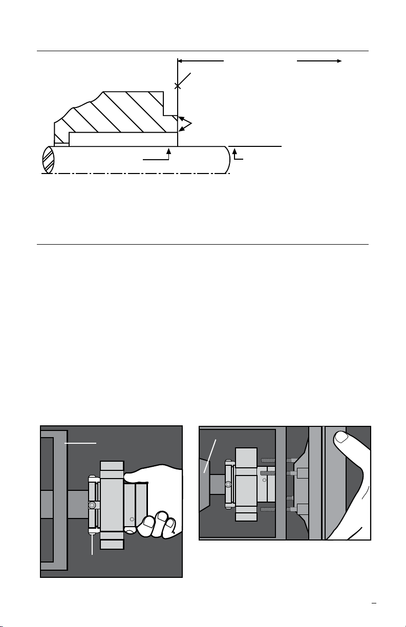
Seal Chamber Requirements Figure 1
Face of seal housing to be square to the axis
of the shaft to within 0.013 mm per millimeter
(0.0005 inches) of seal chamber bore FIM and
have a √1.6
Gland pilot can be at either of these
register locations, concentric to within
Seal housing bore to have √3.2 μm
(125 μinch) R finish or better
Sleeve or shaft finish to be
0.8 μm (32 μinch) R or better
• Bearings must be in good condition
• Maximum lateral or axial movement of shaft (end play) = 0.25 mm (0.010 inch) FIM
• Maximum shaft runout at face of seal housing = 0.05 mm (0.002 inch) FIM
• Maximum dynamic shaft deflection at seal housing = 0.05 mm (0.002 inch) FIM
a
a
0.13 mm (0.005 inch) FIM of shaft or sleeve OD
To first obstruction
μm (63 μinch) R finish or better
Shaft or sleeve OD
+0.000 mm (+0.000 inch)
-0.050 mm (-0.002 inch) ANSI
+0.000 mm (+0.000 inch) API 610/682
-0.025 mm (- 0.001 inch) DIN/ISO
a
2 Uniseal Installation
Note: No seal setting measurements are needed to install the seal. Instructions
are for end-suction back pull-out pumps. Modication of these procedures may be
required for other style pumps. Consult Flowserve for installation support.
2.1 Lubricate the shaft or pump sleeve lightly with silicone lubricant unless
otherwise specied.
2.2 Tighten the setting device cap screws to ensure they are tight before
installation.
2.3 Slide the Uniseal cartridge onto the shaft or pump sleeve with the setting
devices toward the bearing housing. See Figure 2.
2.4 Install the seal chamber and bolt it in place on the bearing frame.
See Figure 3.
2.5 Position the Uniseal with the gland tight against the seal chamber.
Bearing Housing
Bearing Frame
Seal
Chamber
Figure 3
Setting Device
Figure 2
3
Page 4

2.6 Orient the Uniseal with the ports aiming as shown on the seal assembly
drawing. See Section 3 for Piping Recommendations.
2.7 Tighten the gland nuts evenly in a diagonal sequence. Do not over-
tighten the gland nuts, as this can warp seal parts and cause leakage.
Conrm adequate thread engagement before nal torque setting.
Recommended Uniseal minimum gland nut torque by size range:
Seal mm 25 - 50 54 - 67
Size (inch) (1.000 - 2.000) (2.125 - 2.625)
Torque 20 N-m 27 N-m
(15 ft-lbs) (20 ft-lbs)
2.8 Assemble the equipment per manufacturer specications. Avoid pipe
strain. Align the coupling per manufacturer specications.
2.9 With the impeller, shaft, coupling and bearings in their nal operating
position, tighten the drive collar set screws. See Figure 4.
Recommended Uniseal minimum set screw torque by size range:
Seal mm 25 - 60 67
Size (inch) (1.000 - 2.500) (2.625)
Torque 4.5 N-m 13.5 N-m
(40 in-lbs) (120 in-lbs)
Figure 4
2.10 Remove the setting devices from the drive collar by loosening the cap
screws. See Figure 5. Save the setting devices and fasteners for future use
when the pump impeller is reset or when the seal is removed for repairs.
2.11 Turn the shaft by hand to ensure unobstructed rotation.
2.12 See Operational Recommendations before start-up.
4
Figure 5
Page 5

3 Piping Recommendations
CW
Rotation
F
D
F
Q
CCW
Rotation
3.1 Install and maintain an adequate piping plan. The Uniseal requires a
clean, cool environment for maximum seal life. Typical piping plans are
listed below. Contact Flowserve for additional piping plan information or
technical support.
Plan 11: default inner seal ush from pump discharge on horizontal
pumps (single seals)
Plan 13: default inner seal ush and vent from pump suction on
vertical pumps (single seals)
Plan 21: inner seal ush from pump discharge through a cooler for use
with hot products (single seals)
Plan 32: inner seal clean external ush for use with abrasive products
or products that are incompatible with the seal (single seals)
Plan 52: dual seal circulation through a low pressure reservoir
(dual seals)
Plan 53: dual seal circulation through a pressurized reservoir
(53A), nned tube array (53B) or
piston accumulator
(53C) (dual seals)
Plan 62: external quench on
atmospheric side of
seal (single seals)
3.2 For single seals, follow the port
connections listed below, see
Figure 6. Quench and Drain
ports on single seals should be
plugged if not used as a good
housekeeping practice.
a
b
Single seal port connections
Figure 6
For Plans 11, 21 and 32:
Shaft Rotation Inlet Plugged
(from exposed end of gland) Port
Clockwise (CW) Port b Port a
Counterclockwise (CCW) Port a Port b
For Plan 13:
Shaft Rotation Outlet Plugged
(from exposed end of gland) Port
Clockwise (CW) Port a Port b
Counterclockwise (CCW) Port b Port a
5
Page 6

V
3.3 For dual seals, follow the port
connections listed below, see Figure 7.
Uniseals are unidirectional and piping
the correct inlet and outlet is important
to proper circulation. The liquid barrier
inlet should draw from the bottom of the
support system while the liquid barrier
outlet feeds the top of the system. After
venting, plug the vent port.
F
Rotation
a
CCW
b
CW
Rotation
F
Dual seal port connections
Figure 7
For Plans 52 and 53:
Shaft Rotation Inlet Outlet
(from exposed end of gland)
Clockwise (CW) Port b Port a
Counterclockwise (CCW) Port a Port b
3.4 For dual pressurized seal (double seal) operation, supply a clean,
compatible barrier uid at a pressure at least 1.7 bar (25 psi) above the
seal chamber pressure. See Figure 8. The pressure of the barrier uid
must not exceed the recommended maximum pressure.
Dual pressurized (Plan 53A) Uniseal with Supply Tank Figure 8
Image is not to scale
6
Page 7

3.5 For dual unpressurized (tandem seal) operation, supply a clean,
compatible buffer uid at a pressure below the seal chamber pressure.
The pressure in the seal chamber must not exceed the recommended
maximum pressure.
3.6 Dual seal recommendation: For enhanced seal performance and
reduced coking, use DuraClear as a barrier uid. Refer to DuraClear
brochure FSD123 or contact a Flowserve representative for further details.
4 Operational Recommendations
4.1 Remove lock outs on equipment and valves.
4.2 Do not start up the pump dry to check motor rotation or for any other
reason. Open valves to ood pump with product uid. Ensure that the seal
ush or support system is operating. Vent air from the casing of the pump
and the seal chamber before start-up.
4.3 Observe the start-up. If the seal runs hot or squeals, check the seal ush
system. Do not allow the pump to run for any extended time if the seal
gets hot or squeals.
4.4 Do not exceed corrosion limits. The Uniseal is designed to resist
corrosion through proper material selection. Do not expose the Uniseal
materials of construction to products outside of their corrosion limits.
Consult Flowserve for chemical resistance recommendations.
4.5 Do not exceed pressure and speed limits established for the Uniseal.
4.6 Do not exceed the temperature limits of the Uniseal based on the
materials of construction. For dual seals using supply tanks with cooling
coils, turn on cooling water to the supply tank before start-up.
4.7 Do not start up or run the Uniseal dry. The seal chamber, pump and
support systems should be thoroughly vented before start-up. Buffer or
barrier uid must ood the seal cavity of dual seals at all times during
operation. Process uid must be in the seal chamber at all times during
single seal operation.
7
Page 8

TO REORDER REFER TO
flowserve.com
B/M #
F.O
.
5 Repairs
This product is a precision sealing device. The design and dimension tolerances
are critical to seal performance. Only parts supplied by Flowserve should be used
to repair a seal. To order replacement parts, refer to the part code and B/M
number. A spare backup seal should be stocked to reduce repair time.
When seals are returned to Flowserve for repair, decontaminate the seal
assembly and include an order marked "Repair or Replace." A signed
certicate of decontamination must be attached. A Material Safety Data
Sheet (MSDS) must be enclosed for any product that came in contact with
the seal. The seal assembly will be inspected and, if repairable, it will be rebuilt,
tested, and returned.
FIS213eng REV 05/13 Printed in USA
To find your local Flowserve representative
and find out more about Flowserve Corporation,
visit www.flowserve.com
Flowserve Corporation has established industry leadership in the design and manufacture of its products. When
properly selected, this Flowserve product is designed to perform its intended function safely during its useful life.
However, the purchaser or user of Flowserve products should be aware that Flowserve products might be used
in numerous applications under a wide variety of industrial service conditions. Although Flowserve can provide
general guidelines, it cannot provide specific data and warnings for all possible applications. The purchaser/user
must therefore assume the ultimate responsibility for the proper sizing and selection, installation, operation, and
maintenance of Flowserve products. The purchaser/user should read and understand the Installation Instructions
included with the product, and train its employees and contractors in the safe use of Flowserve products in connection
with the specific application.
While the information and specifications contained in this literature are believed to be accurate, they are supplied for
informative purposes only and should not be considered certified or as a guarantee of satisfactory results by reliance
thereon. Nothing contained herein is to be construed as a warranty or guarantee, express or implied, regarding any
matter with respect to this product. Because Flowserve is continually improving and upgrading its product design,
the specifications, dimensions and information contained herein are subject to change without notice. Should any
question arise concerning these provisions, the purchaser/user should contact Flowserve Corporation at any one of
its worldwide operations or offices.
© 2013 Flowserve Corporation
USA and Canada
Kalamazoo, Michigan USA
Telephone: 1 269 381 2650
Telefax: 1 269 382 8726
Europe, Middle East, Africa
Roosendaal, the Netherlands
Telephone: 31 165 581400
Telefax: 31 165 554590
Asia Pacific
Singapore
Telephone: 65 6544 6800
Telefax: 65 6214 0541
Latin America
Mexico City
Telephone: 52 55 5567 7170
Telefax: 52 55 5567 4224
 Loading...