

Page 1

GESTRA
GESTRA Steam Systems
UNA 38
UNA 39
Installation Instructions 818603-00
Steam Traps
UNA 38, UNA 39
1
Page 2

Contents
Page
Important Notes
Usage for the intended purpose ..............................................................................................................4
Safety note ............................................................................................................................................. 4
Danger ...................................................................................................................................................4
Attention .................................................................................................................................................4
PED (Pressure Equipment Directive) ........................................................................................................4
ATEX (Atmosphère Explosible) .................................................................................................................4
Explanatory Notes
Scope of supply ...................................................................................................................................... 5
Description ............................................................................................................................................. 5
Function ...........................................................................................................................................5 – 6
Technical Data
UNA 38, UNA 39 ......................................................................................................................................6
Pressure/temperature ratings .................................................................................................................6
Corrosion resistance ............................................................................................................................... 6
Sizing .....................................................................................................................................................6
Name plate/marking ...............................................................................................................................7
Design
UNA 38, UNA 39 ..............................................................................................................................8 – 10
Key .......................................................................................................................................................11
Installation
UNA 38, UNA 39 ....................................................................................................................................12
Design with flanges .............................................................................................................................. 12
Design with socket-weld ends .............................................................................................................. 12
Design with butt-weld ends .................................................................................................................. 12
Attention ...............................................................................................................................................12
Heat treatment of welds........................................................................................................................13
Hand vent valve (UNA 38)......................................................................................................................13
Float lifting lever (optional extra) ........................................................................................................... 13
Tools .....................................................................................................................................................13
Commissioning
Danger .................................................................................................................................................13
UNA 38, UNA 39 ...................................................................................................................................13
2
Page 3

Contents – continued –
Page
Operation
Danger .................................................................................................................................................14
Hand vent valve .................................................................................................................................... 14
Float lifting lever ................................................................................................................................... 14
Maintenance
Checking the steam trap .......................................................................................................................15
Cleaning /exchanging the control unit ....................................................................................................15
Changing the bimetallic air vent (UNA 38) ............................................................................................. 15
Torques ................................................................................................................................................ 16
Tools .....................................................................................................................................................16
Retrofitting
Cleaning /exchanging the control unit ....................................................................................................17
Torques ................................................................................................................................................ 17
Tools .....................................................................................................................................................17
Spare Parts
Spare parts list UNA 38, UNA 39 ........................................................................................................... 18
Annex
Declaration of conformity ......................................................................................................................19
3
Page 4
Important Notes
Usage for the intended purpose
UNA 38, UNA 39:
Use the steam traps only for the discharge of condensed steam and liquids. Use the equipment for
the discharge of condensed steam and other condensable gases in pipes only within the specified
pressure and temperature ratings, and check the corrosion resistance and chemical suitability for the
application in question.
Safety note
The equipment must only be installed and commissioned by qualified staff.
Maintenance and service work must only be performed by adequately trained persons who have
a recognized level of competence.
Danger
The steam trap is under pressure during operation.
When loosening flanged connections, sealing plugs or the control unit, it is possible
that hot water, steam, corrosive liquids or toxic gases may escape.
This presents the danger of severe burns and scalds to the whole body or severe cases
of poisoning by toxic gases.
Installation and maintenance work should only be carried out when the system is
depressurized.
Isolate the trap from both upstream and downstream pressure.
The steam trap becomes hot during operation.
This presents the risk of severe burns to the whole body.
Before performing maintenance work on the valve or flanged connections or undoing
the gland packing screws or sealing plugs, ensure that all the connected pipes are
pressureless (0 bar) and have cooled down to room temperature (20 °C).
Attention
The name plate indicates the technical specification of the equipment.
Do not commission or operate a steam trap without a name plate.
PED (Pressure Equipment Directive)
The equipment fulfils the requirements of the Pressure Equipment Directive PED 97/23/EC.
UNA 38 and UNA 39 are intended for applications with fluids of group 1 and 2.
With CE marking (apart from equipment according to section 3.3).
ATEX (Atmosphère Explosible)
The equipment does not have its own potential source of ignition and is therefore not subject to the
ATEX Directive 94/9/EC. The equipment can be used in potentially explosive areas 0, 1, 2, 20, 21, 22
(1999/92/EC).
The equipment is not Ex marked.
4
Page 5

Explanatory Notes
Scope of supply
UNA 38 with DUPLEX control unit
loat trap UNA 38
1 F
1 Installation manual
UNA 39 with DUPLEX control unit
1 Foat trap UNA 39
1 Installation manual
Retrofit set for UNA 38, UNA 39
1 Control unit as per specification
1 Installation manual
Spare parts
1 Set according to spare parts list on page 18
Description
UNA 3... are high-pressure steam traps with ball float and needle closing mechanism. The steam traps
work independently of back pressure, thus ensuring universal application.
The steam trap UNA 3… features a body with bolted cover and a control unit. Various control units
are available.
Level-dependent SIMPLEX control is particularly suitable for cold condensate and superheated steam.
Temperature-dependent DUPLEX control offers automatic deaeration by means of a bimetallic air vent
for saturated and superheated steam systems.
The orifice type O 80 MAX (UNA 38) is a control unit for large flowrates and high pressures, and can
be supplied as a SIMPLEX or DUPLEX version.
The orifice type O 140 MAX (UNA 39) is a SIMPLEX control unit for large flowrates and high pressures.
UNA 38 with SIMPLEX control unit
1 Float trap UNA 38
1 Hand vent valve with gasket, installed
1 Float lifting lever with gasket, installed (optional)
1 Installation manual
UNA 39 with SIMPLEX control unit
1 Float trap UNA 39
1 Hand vent valve with gasket, installed
1 Float lifting lever with gasket, installed (optional)
1 Installation manual
.
Function
UNA 38, UNA 39:
The ball valve of the control unit is operated by the float as a function of the condensate level in the
trap. The cross-sectional area (CSA) of the orifice (O) dictates the maximum flowrate when the valve is
completely open. The maximum admissible differential pressure of the control unit is a function of the
CSA of the orifice, the density of the fluid to be discharged, and the pressure/temperature ratings of the
body. Different closing units (orifices) are available.
Float traps equipped with DUPLEX control units enable automatic temperature-dependent deaeration
of saturated steam systems during start-up and in continuous operation.
5
Page 6
Explanatory Notes – continued –
Function – continued –
UNA 38 control unit O 80 MAX and UNA 39 control unit O 140 MAX:
The float ball controls a pilot valve depending on the level of condensate in the trap body. If more
condensate flows through the pilot valve out of the control chamber than follows through a balance
opening, the pressure in the control chamber drops and the bellows of the control chamber is
compressed. The main valve then opens and the condensate is discharged.
The flowing condensate moves the float ball upwards and the pilot valve closes. By means of the vent
hole, the pressure between the control chamber and the interior of the steam trap is evened out, so
that the main valve closes.
The cross-sectional areas of the pilot and main valves are chosen so that only one orifice (O) is needed
for the entire range of differential pressures up to 80 bar (or 140 bar).
Technical Data
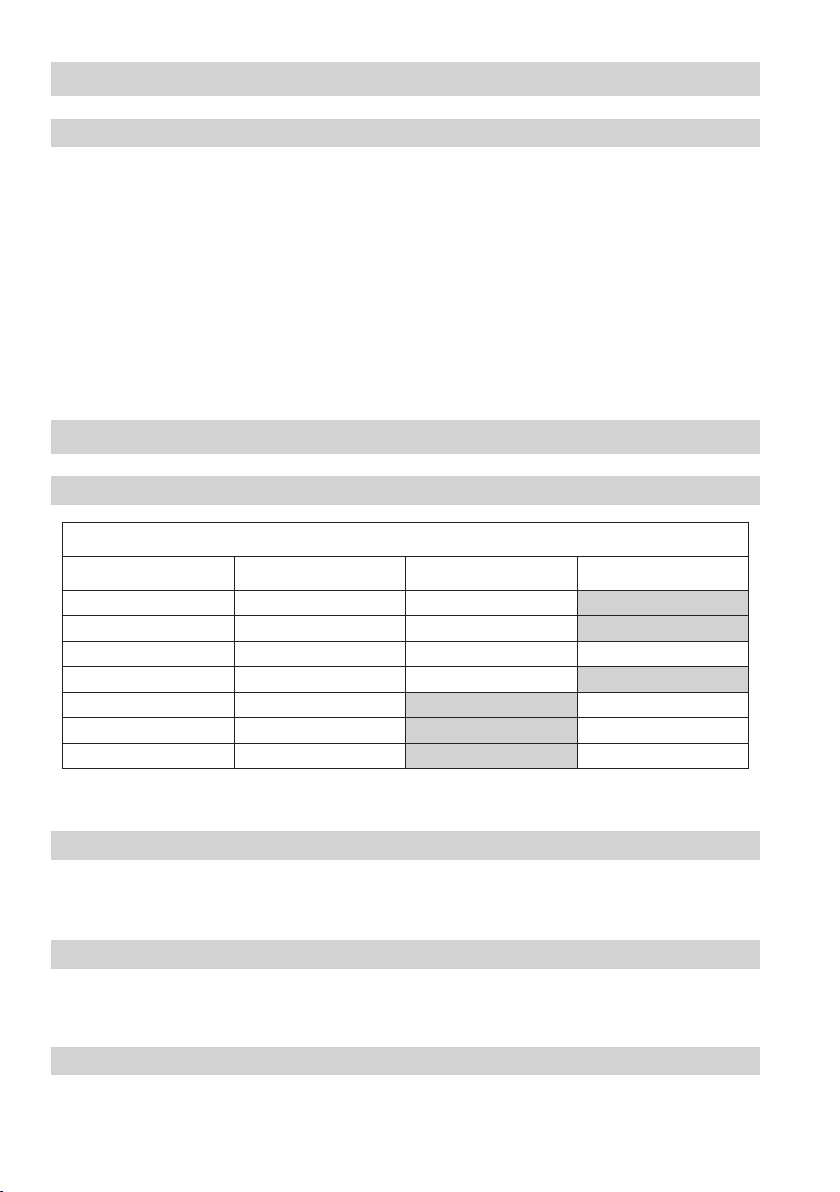
UNA 38, UNA 39
Orifices (O)
Type
O 50 50 X
O 64 64 X
O 80 80 X X
O 80 MAX 80 X
O 110 110
O 140 140
O 140 MAX 140
1
) Observe the pressure/temperature ratings!
2
) Inlet pressure minus outlet pressure.
∆PMX [bar] 1)2)
UNA 38 UNA 39
X
X
X
Pressure/temperature ratings
For the pressure and temperature ratings, see the designation on the body or the data given on the
name plate.
Corrosion resistance
When used for its intended purpose, the safe functioning of the steam trap will not be impaired by
corrosion.
Sizing
The trap body must not be subjected to sharp increases in pressure. The sizing and dimensional
allowances for corrosion reflect the latest state of technology.
6
Page 7

Technical Data – continued –
Name plate / marking
For the pressure and temperature ratings, see the designation on the trap body or the data given on
the name plate. Further details are given in various GESTRA publications, such as datasheets and
technical information.
In accordance with EN 19, the following type and design data are indicated on the name plate or body:
n Manufacturer
n Type designation
n Pressure class PN or Class
n Material number
n Maximum temperature
n Maximum pressure
n Direction of flow
n Stamp on the body / name plate, e.g. specifies the manufacturing quarter and year
(in this case the 3rd quarter of 2005).
n Type designation UNA 38 h: design for horizontal lines
UNA 38 v: design for vertical lines
UNA 39: angle type
n SIMPLEX or DUPLEX: type of control unit (see Description)
n ∆PMX (∆p max): max. admissible differential pressure [bar],
corresponding to the ordered “O...” (orifice).
3
05
Maximum
admissible
differential
pressure
Fig. 1
Nominal size Nominal pressure
Maximum admissible pressure
Design/version
Maximum
admissible
temperature
Design
7
Page 8

Design
UNA 38
Fig. 2 UNA 38h
k
;
<
l
X
:
C
D
z
E
F
G
L
O
C
N
r
s
G
L
t
u
w
8
Page 9

Design – continued –
UNA 38 – continued –
Fig. 3 UNA 38v
9
Page 10

Design – continued –
UNA 39
r
2
2
u
2
t
Fig. 4 UNA 39
W
V
<
2
U
2
:
z
T
2
2
w
;
2
L
l
2
t
2
2
s
2
k
N
L
O
Fig. 5 UNA 39
10
Page 11

Design – continued –
Key to components
k UNA 38 hexagon nut M20
l UNA 38 sleeve
C UNA 38 bimetallic air vent
D Gasket, shape A 16 x 20
E UNA 38 control unit DUPLEX,
Orifice 50, O 64 or O 80
F Plug
G Gasket, shape D 17 x 21
r UNA 38 control unit DUPLEX,
Orifice 80 MAX
s UNA 38 hand vent valve
t UNA 38 handle for float lifting lever
u UNA 38 float lifting lever
L Gasket, shape D 21 x 26
w UNA 38 cover
N Name plate
O Plug
2
k UNA 39 hexagon nut M24
2
l UNA 39 sleeve
2
r UNA 39 control unit,
Orifice 140 MAX
2
s UNA 39 hand vent valve
2
t UNA 39 handle for float lifting lever
2
u UNA 39 float lifting lever
2
w UNA 39 cover
z UNA 38 expansion bolt
: UNA 38 body gasket 129 x 141 x 1
; UNA 38 control unit SIMPLEX,
Orifice 50, O 64 or O 80
< UNA 38 body
T Hexagon-socket screw
U Gasket 30 x 40 x 1
V UNA 39 split pin for float lifting lever
W UNA 39 distance sleeve for float lifting lever
X UNA 38 union nut
2
z UNA 39 expansion bolt
2
: UNA 39 body gasket 182 x 112 x 1
2
; UNA 39 control unit SIMPLEX,
Orifice 80, O 110 or O 140
2
< UNA 39 body
11
Page 12

Installation
UNA 38
Depending on its body design, the float trap UNA 38 can be installed in horizontal or vertical pipes with
downward flow.
UNA 39
The float trap UNA 39 can be installed in vertical pipes with downward flow.
Design with flanges
1. Ensure correct position of installation. The name plate
2. Observe direction of flow. The arrow indicating the flow direction is on the trap body.
3. Consider space required for opening trap. When the trap is installed, a minimum space of at least
150 mm (UNA 39) or 310 mm (UNA 38) is required for removing the cover M.
4. Remove plastic plugs. They are
5. Clean the seating surfaces of both flanges.
6. Install the steam trap.
Design with socket-weld ends
1. Ensure correct position of installation. The name plate N must always be on top (UNA 38).
2. Observe direction of flow. The arrow indicating the flow direction is on the trap body.
3. Consider space required for opening trap. When the trap is installed, a minimum space of at least
150 mm (UNA 39) or 310 mm (UNA 38) is required for removing the cover M.
4. Remove plastic plugs. They are
5. Clean the socket-weld ends.
6. Arc-weld the trap
Design with butt-weld ends
1. Ensure correct position of installation. The name plate
2. Observe direction of flow. The arrow indicating the flow direction is on the trap body.
3. Consider space required for opening trap. When the trap is installed, a minimum space of at least
150 mm (UNA 39) or 310 mm (UNA 38) is required for removing the cover M.
4. Remove plastic plugs. They are
5. Clean the butt-weld ends.
6. Arc-weld the trap manually (welding process 111 and 141 in accordance with ISO 4063) or use
gas-welding (welding process 3 in accordance with ISO 4063).
only manually (welding process 111 and 141 in accordance with ISO 4063).
only used as transit protection.
only used as transit protection.
only used as transit protection.
N must always be on top (UNA 38).
N must always be on top (UNA 38).
12
Attention
n
Only qualified welders certified e.g. according to EN 287-1 may weld the steam trap
into pressurized lines.
Page 13

Installation – continued –
Heat treatment of welds
After welding the steam trap, it may be necessary to apply heat treatment to the welds (stress-relief
annealing as per DIN EN 100529).
The heat treatment is limited to the area immediately around the weld.
It is not necessary to remove the internals of the steam trap to perform the heat treatment.
Hand vent valve (UNA 38)
Remove plug F.
1.
Insert the gasket G and fit the hand vent valve I in place.
2.
For the torque, see the table “Torques”.
Close the hand vent valve.
3.
Float lifting lever (optional extra)
For the UNA 38 and UNA 39, the float lifting lever is installed in the factory.
Tools
n Combination spanner A.F. 22 mm to DIN 3113, form B
n Torque spanner 20 – 120 Nm to DIN ISO 6789
Commissioning
Danger
Burn hazard! The steam trap becomes hot during operation. Touching the hand vent valve
or the float lifting lever presents the risk of severe burns to hands and arms.
Always wear insulated, heat-resistant safety gloves when handling the valve.
UNA 38, UNA 39
Make sure that all flanged connections, the hand vent valve and the float lifting lever are firmly fixed to
the UNA 38 or UNA 39, ensuring a tight, leakproof joint.
If the steam trap is to be used in a new installation which has not been flushed yet, it is advisable to
check – and if required – clean the trap.
13
Page 14

Operation
Danger
Burn hazard! The steam trap becomes hot during operation. Touching the hand vent valve
or the float lifting lever presents the risk of severe burns to hands and arms.
Always wear insulated, heat-resistant safety gloves when handling the valve.
Hand vent valve
1. Open the hand vent valve if necessary.
2. Close the hand vent valve after completing the venting process.
Float lifting lever
1. Attach the handle J to the float lifting lever K. (See Fig. 2 and Fig. 4)
2. Turn the float lifting lever
3. Turn the float lifting lever in the opposite direction to the arrow (to close the valve),
and then remove the handle.
K in the direction of the arrow on the cover M.
14
Page 15

Maintenance
GESTRA steam traps of the type UNA do not require any special maintenance.
However, if the steam trap is to be used in a new installation which has not been flushed yet,
it is advisable to check and – if required – clean the trap.
Checking the steam trap
The UNA steam traps can be checked for steam loss during operation by using the GESTRA ultrasonic
measuring unit VAPOPHONE® or TRAPtest®.
In case of steam loss, clean the valve and/or replace the control unit or orifice.
Cleaning/exchanging the control unit
1. Take heed of the “Danger” note on page 4.
2. Undo the hexagon nuts
the cover M.
3. Undo the union nut
alternatively, undo and remove the hexagon socket-head screws T, and take out the control unit
2 2
r or ; (UNA 39).
Replace the control unit in case of visible signs of wear or damage.
4.
Clean the body, internals and all gasket surfaces.
5.
Apply heat-resistant lubricant to all threads and the seating surfaces of the control unit and cover
6.
(use e.g. WINIX® 2150).
Attach the control unit E, r or ; (UNA 38) with the union nut and align it within the body so that the
7.
float ball can move vertically. Tighten the union nut. Insert a new gasket U for control unit r or ;
(UNA 39), put on the control unit and tighten the hexagon socket-head screws T evenly crosswise.
For the torques, see the table “Torques” on page 16.
Insert a new body gasket Q.
8.
Put the cover onto the body and push the sleeves B onto the expansion bolts P. Tighten the
9.
hexagon nuts A evenly crosswise in several stages to the values specified in the “Torques” table.
A, remove the sleeves B from the expansion bolts P, and take off
X and take it out of the body together with the control unit E, r or ; (UNA 38);
2 2
Changing the bimetallic air vent (UNA 38)
1. Take heed of the “Danger” note on page 4.
2. Undo the hexagon nuts
k, remove the sleeves l from the expansion bolts z, and take off
the cover w.
Unscrew and remove the bimetallic air vent C; take out the gasket D.
3.
Install a new bimetallic air vent C together with a new gasket. For the torque, see the table “Torques”
4.
on page 16.
Insert a new body gasket :.
5.
Put the cover onto the body and push the sleeves l onto the expansion bolts z. Tighten the hexagon
6.
nuts k evenly crosswise in several stages to the values specified in the “Torques” table.
WINIX® 2150 is a registered trademark of WINIX GmbH, Norderstedt
15
Page 16
Maintenance – Continued –
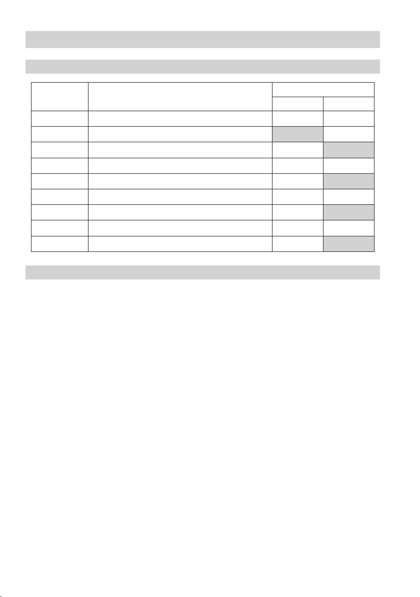
Torques
Item Designation
A
T
X
P
C
I
K
O
F
Hexagon-socket screw (UNA 39)
Hexagon nut
Union nut (UNA 38)
Expansion bolts
Bimetallic air vent
Hand vent valve
Float lifting lever
Plug
Plug
Tools
n Combination spanner A.F. 17, 19, 22, 24, 30, 46 mm to DIN 3113, form B
n Allen key A.F. 5, 8 mm to ISO 2936
n Torque spanner 10–60 Nm, 60–120 Nm, 120–300 Nm to DIN ISO 6789
Torque [Nm]
UNA 38 UNA 39
270 340
40
120
20 20
90
70 170
110
70 170
110
16
Page 17

Retrofitting
GESTRA steam traps can be retrofitted with different control units.
Cleaning /exchanging the control unit
1. Take heed of the “Danger” note on page 4.
2. Undo the hexagon nuts
the cover M.
3. Undo the union nut
alternatively, undo and remove the hexagon socket-head screws T, and take out the control unit
2 2
r or ; (UNA 39).
Replace the control unit in case of visible signs of wear or damage.
4.
Clean the body, internals and all gasket surfaces.
5.
Apply heat-resistant lubricant to all threads and the seating surfaces of the control unit and cover
6.
(use e.g. WINIX® 2150).
Attach the control unit E, r or ; (UNA 38) with the union nut and align it within the body so that the
7.
float ball can move vertically. Tighten the union nut. Insert a new gasket U for control unit r or ;
(UNA 39), put on the control unit and tighten the hexagon socket-head screws T evenly crosswise.
For the torques, see the table “Torques” on page 16.
Insert a new body gasket Q.
8.
Put the cover onto the body and push the sleeves B onto the expansion bolts P. Tighten the
9.
hexagon nuts A evenly crosswise in several stages to the values specified in the “Torques” table.
Torques
A, remove the sleeves B from the expansion bolts P, and take off
X and take it out of the body together with the control unit E, r or ; (UNA 38);
2 2
Item Designation
A
T
X
P
C
I
K
O
F
Hexagon-socket screw (UNA 39)
Hexagon nut
Union nut (UNA 38)
Expansion bolts
Bimetallic air vent
Hand vent valve
Float lifting lever
Plug
Plug
Tools
n Combination spanner A.F. 17, 19, 22, 24, 30, 46 mm to DIN 3113, form B
n Allen key A.F. 5, 8 mm to ISO 2936
n Torque spanner 10–60 Nm, 60–120 Nm, 120–300 Nm to DIN ISO 6789
WINIX® 2150 is a registered trademark of WINIX GmbH, Norderstedt
Torque [Nm]
UNA 38 UNA 39
270 340
40
120
20 20
90
70 170
110
70 170
110
17
Page 18

Spare Parts
Spare parts list UNA 38
Designation
Item
Body gasket (graphite/CrNi) 524532
:
Control unit DUPLEX
E
with body gasket
r
Control unit SIMPLEX
;
with body gasket
Hand vent valve with gasket 560559
s
Float lifting lever with gasket 560560
u
Bimetallic air vent EBK 39 (only for Duplex control units) with gasket 560558
C
O = Orifice
Spare parts list UNA 39
Designation
Item
2
Body gasket (graphite/CrNi) 523031
:
2
Control unit, complete
r
2
with body gasket
;
2
Hand vent valve with gasket 560178
u
O = Orifice
Order no.
DN 15-50
O 50 560550
0 64 560551
O 80 560552
O 80 MAX 560553
O 50 560554
O 64 560555
O 80 560556
O 80 MAX 560557
Order no.
DN 15-50
O 80 560172
O 110 560171
O 140 560170
O 140 MAX 560179
18
Page 19

Annex
CE Declaration of Conformity
We hereby declare that the items of pressure equipment UNA 38 and UNA 39 conform to the following
European Directive:
n EC Pressure Equipment Directive (PED) 97/23/EC dated 29 May 1997, apart from the equipment
according to section 3.3.
n Applied conformity assessment procedure according to Annex III, module H, verified by Notified
Body 0525.
This declaration is no longer valid if modifications are made to the equipment without prior
consultation with us.
Bremen, 11 October 2005
GESTRA AG
Dipl.-Ing. Uwe Bledschun
Head of Design Dept.
Dipl.-Ing. Lars Bohl
Quality Assurance Representative
19
Page 20

Agencies all over the world:
www.gestra.de
GESTRA
España
GESTRA ESPAÑOLA S.A.
Luis Cabrera, 86-88
E-28002 Madrid
Tel. 00 34 91 / 5 15 20 32
Fax 00 34 91 / 4 13 67 47; 5 15 20 36
E-mail: aromero@flowserve.com
Great Britain
Flowserve Flow Control (UK) Ltd.
Burrel Road, Haywards Heath
West Sussex RH 16 1TL
Tel. 00 44 14 44 / 31 44 00
Fax 00 44 14 44 / 31 45 57
E-mail: gestraukinfo@flowserve.com
Italia
Flowserve S.p.A.
Flow Control Division
Via Prealpi, 30
l-20032 Cormano (MI)
Tel. 00 39 02 / 66 32 51
Fax 00 39 02 / 66 32 55 60
E-mail: infoitaly@flowserve.com
Polska
GESTRA POLONIA Spolka z.o.o.
Ul. Schuberta 104
PL - 80-172 Gdansk
Tel. 00 48 58 / 3 06 10 -02 od 10
Fax 00 48 58 / 3 06 33 00
E-mail: gestra@gestra.pl
Portugal
Flowserve Portuguesa, Lda.
Av. Dr. Antunes Guimarães, 1159
Porto 4100-082
Tel. 0 03 51 22 / 6 19 87 70
Fax 0 03 51 22 / 6 10 75 75
E-mail: jtavares@flowserve.com
USA
Flowserve DALCO Steam Products
2601 Grassland Drive
Louisville, KY 40299
Tel.: 00 15 02 / 4 95 01 54, 4 95 17 88
Fax: 00 15 02 / 4 95 16 08
E-mail: dgoodwin@flowserve.com
GESTRA AG
P. O. Box 10 54 60, D-28054 Bremen
Münchener Str. 77, D-28215 Bremen
Telephone +49 (0) 421 35 03- 0
Fax +49 (0) 421 35 03 - 393
E-Mail gestra.ag@flowserve.com
Internet www.gestra.de
818603-00/1205cm · © 2005 GESTRA AG · Bremen · Printed in Germany
20
 Loading...