

Page 1

GESTRA
GESTRA Steam Systems
UNA 14
UNA 16
UNA 16A (Stainless Steel)
UNA 14P
Installation Instructions 810877-01
Steam Traps UNA 14, UNA 16, UNA 16A
Air Trap for Compressed Air and Gases UNA 14P
1
Page 2

Contents
Page
Important Notes
Usage for the intended purpose ............................................................................................................. 8
Safety note ............................................................................................................................................ 8
Danger ................................................................................................................................................... 8
Classification pursuant to article 9 of the Pressure Equipment Directive (PED) ..................................... 9
Explanatory Notes
Scope of supply ..................................................................................................................................... 9
Description .......................................................................................................................................... 10
Function............................................................................................................................................... 10
Technical data ............................................................................................................................... 11, 12
Corrosion resistance ............................................................................................................................ 13
Sizing................................................................................................................................................... 13
Name plate/marking ........................................................................................................................... 13
Installation
UNA 14, UNA 16, UNA 16A, UNA 14P ...................................................................................................13
Flanged design .................................................................................................................................... 13
Screwed-socket design ...................................................................................................................... 14
Socket-weld design ............................................................................................................................ 14
Butt-weld design ................................................................................................................................14
Heat treatment of welds ...................................................................................................................... 15
Change direction of flow ...................................................................................................................... 15
Air balance pipe................................................................................................................................... 15
Hand vent valve (optional extra) .......................................................................................................... 16
Float-lifting lever (optional extra) ........................................................................................................ 16
Commissioning
UNA 14, UNA 16, UNA 16A, UNA 14P ................................................................................................... 16
Maintenance
Clean trap ............................................................................................................................................ 17
Clean/replace control unit.................................................................................................................... 17
Clean/replace control unit (only DUPLEX design) ................................................................................. 18
Torques ............................................................................................................................................... 18
Spare Parts
Spare parts list .................................................................................................................................... 19
2
Page 3
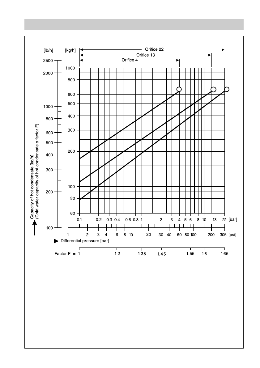
Capacity Charts UNA 14, UNA 16, UNA 16A
1 2 3
Fig. 1
Orifice 4, DN 15 - 25, ½" - 1"
1
Orifice 13, DN 15 - 25, ½" - 1"
2
Orifice 22, DN 15 - 25, ½" - 1" (only UNA 16)
3
3
Page 4
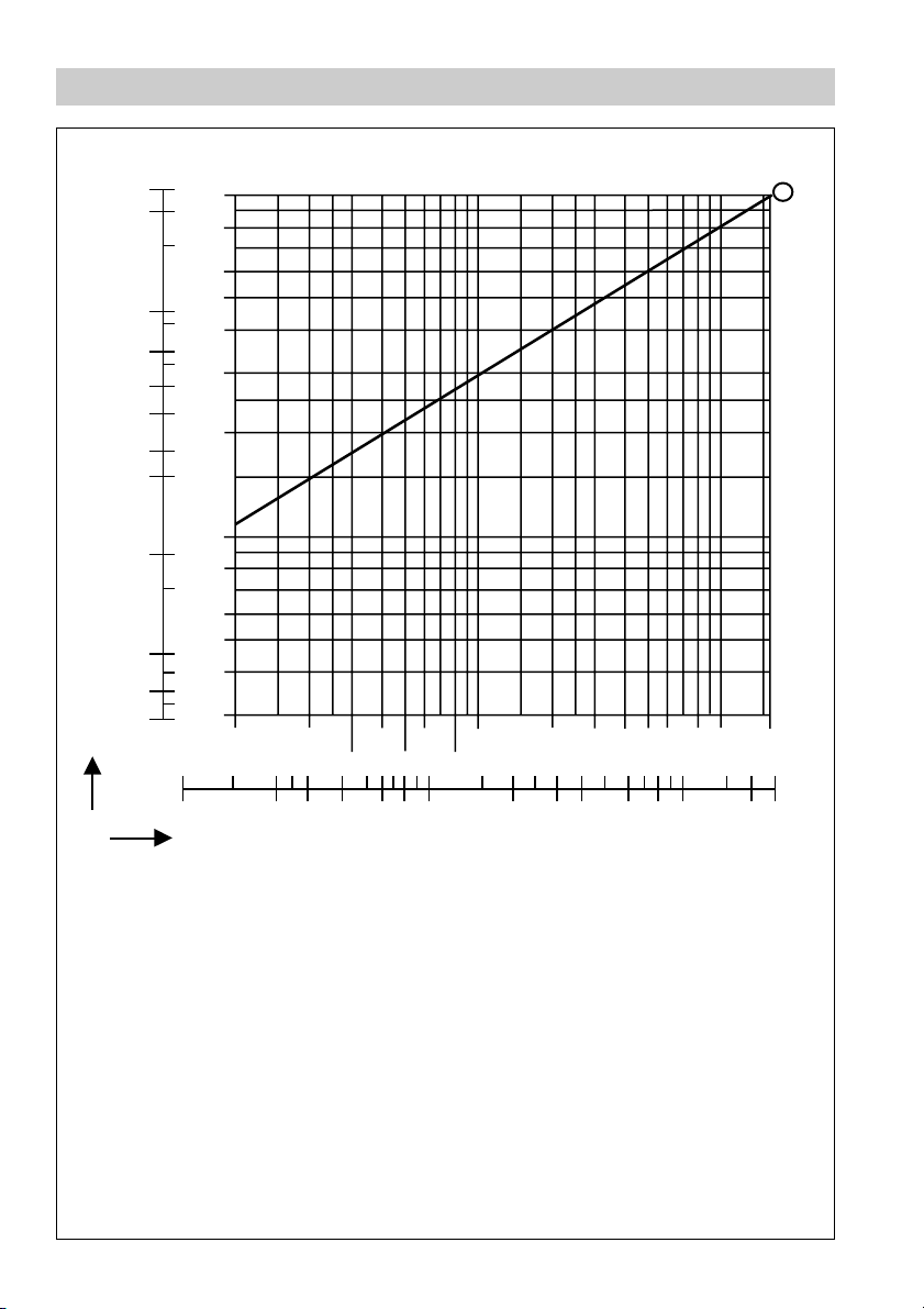
Capacity Chart UNA 14P
lb/h kg/h
2000
1000
800
600
500
400
300
200
100
Capacity of cold condensate [kg/h]
1000
800
600
500
400
300
200
100
80
60
50
80
60
40
30
0.1 0.2 0.4 0.6 1 2 3 4 5 6 8 10 16
4
bar
0.3 0.5 0.8
4
Fig. 2
1 2 3 4 6 8 10 20 30 40 60 80 100 200
Differential pressure (assuming discharge to atmospheric pressure)
Max. capacity of cold condensate
4
from liquids or gases.
psi
Page 5
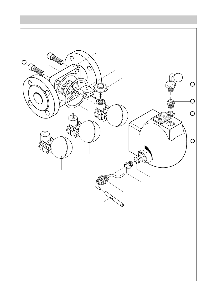
Design
B
P
A
Fig. 3
L
O
M
K
C
N
D
F
G
H
I
H
G
J
5
Page 6
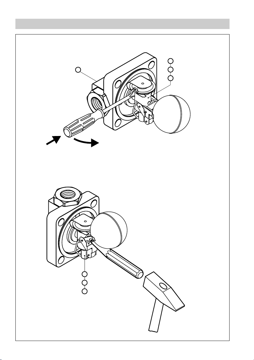
Maintenance
Fig. 4
A
L
M
N
L
M
N
Fig. 5
6
Page 7

Key
Flow direction arrow
A
Body
B
Retainer
C
Thermostatic capsule (5N2)
D
Name plate
E
Hand vent valve (optional extra)
F
Plug*) (optional extra)
G
Gasket*) C 17 x 23 (optional extra)
H
Cover (standard design without holes)
I
Manual float-lifting lever*) (optional extra)
J
Lever extension for float-lifting device*) (optional extra)
K
Control unit SIMPLEX or SIMPLEX P*) for UNA 14P with Perbunan® valve ball
L
Control unit SIMPLEX R
M
Control unit DUPLEX
N
Cover gasket 77 x 67 x1 (graphite/CrNi)
O
Socket-head cap screw
P
*) Standard version of air trap type UNA 14P
Perbunan® is a registered trademark of Bayer AG, Leverkusen
7
Page 8

Important Notes
Usage for the intended purpose
Use steam traps UNA 14, UNA 16, UNA 16A and air trap UNA 14P only for the discharge of condensate
and liquids.
UNA 14, UNA 16, UNA 16A:
Use the equipment only for the discharge of condensate from steam lines within the specified pressure
and temperature ratings and check the corrosion resistance and chemical suitability for the application
in question.
UNA 14P:
Use the equipment only for the discharge of condensate from compressed air lines or other gas lines
within the specified pressure and temperature ratings and check the corrosion resistance and chemical
suitability for the application in question.
Safety note
The equipment must only be installed by qualified staff.
Qualified staff are those persons who – through adequate training in engineering, the use and
application of equipment in accordance with regulations concerning steam systems, and first aid &
accident prevention – have achieved a recognised level of competence appropriate to the installation
and commissioning of this device.
Danger
The trap is under pressure during operation.
When loosening flanged connections, plugs or the control unit hot water, steam,
corrosive fluids or toxic gases may escape.
This presents the risk of severe scalds and acid burns to the whole body.
Toxic gases may cause severe cases of poisoning.
Before carrying out installation and maintenance work make sure the system is
depressurized.
Isolate the trap from both upstream and downstream pressure.
The trap becomes hot during operation.
This presents the risk of severe burns to hands and arms.
Before carrying out installation and maintenance work make sure that the trap is cold.
Sharp edges on internals present a danger of cuts to hands. Always wear industrial
gloves when replacing the control unit.
8
Page 9

Classification pursuant to article 9 of the Pressure Equipment Directive (PED)
UNA 14, UNA 16, UNA 14P UNA 16A (Stainless steel)
Fluid group
Use no yes no yes yes yes yes yes
Category Exception pursuant to article 3.3 Exception pursuant to article 3.3
Nominal size DN 15 –25 15 –25
CE marking no no
Type all all
gas liquid gas liquid
12121212
Explanatory Notes
Scope of supply
UNA 14
1 Steam trap UNA 14
1 Installation manual
UNA 16
1 Steam trap UNA 16
1 Installation manual
UNA 16A (stainless steel)
1 Steam trap UNA 16 A (stainless steel)
1 Installation manual
UNA 14P
1 Air trap UNA 14P
1 Lever extension for manual float-lifting device
1 Installation manual
9
Page 10

Explanatory Notes – continued –
Description
UNA 14, UNA 16, UNA 16A, UNA 14P are steam/air traps with ball float and rolling ball valve. The
steam traps can be used for all operating conditions, as they are unaffected by back pressure. They
consist of a body with bolted cover and a control unit. The control unit is freely accessible after
removing the cover. It can be completely replaced without having to remove the valve body from the
line. A conversion of “h” design to “v” design or vice versa is possible without any problem by
repositioning body and control unit. The direction of flow is indicated by an arrow, the position of
installation by the word “Top” on the name plate.
■ suitable for large condensate flowrates
■ “h”-design for horizontal lines
■ “v”-design for vertical lines
(To convert “h” to “v” design or vice versa turn cover and control unit respectively)
UNA 14, UNA 16, UNA 16A
Three different control units are available: Control unit “SIMPLEX”: level-dependent float control
particularly suitable for cold condensate. Control unit “SIMPLEX R”: level-dependent float control
with internal vent pipe for continuous air-venting. Control unit “DUPLEX”: float control with
temperature-dependent automatic air-venting of saturated steam systems.
UNA 14P
The air trap is suitable for draining compressed air and gas systems. Two different control units are
available: Control unit “SIMPLEX” with steel valve ball or control unit “SIMPLEX P” with Perbunan
valve ball. The air traps feature as standard a manual purging device (float-lifting lever) and a 3/8"
BSP connection (with plug) for subsequent fitting of an air-balance pipe.
Function
®
As the condensate flows into the steam trap it operates the float, which in turn opens the rolling ball
valve of the control unit, and in doing so uncovers the discharge passage. The cross-sectional area
of the orifice dictates the max. flowrate when the discharge passage is completely open. The max.
allowable differential pressure of the control unit used depends on the cross-sectional area of the
orifice and the density of the fluid to be discharged.
Three different orifices are available (retrofitting possible).
Float-operated steam traps equipped with control units DUPLEX enable automatic temperaturedependent deaeration of saturated steam systems at start-up and during continuous operation.
The air trap UNA 14P features an orifice as standard which is rated for a max. differential pressure of
up to 16 bar and a liquid density of
ρ = 1000 kg/m
3
. Note that lower densities reduce the max.
service range accordingly.
The flowrates are indicated in the capacity charts. Air traps for other pressure ratings are available
on request.
Perbunan® is a registered trademark of Bayer AG, Leverkusen
10
Page 11

Technical Data
Max. admissible
Orifices (O) UNA 14 UNA 16 UNA 16A UNA 14P
differential pressure
∆∆
∆PMX [bar]
∆∆
1)2
)
Orifice 4 4 X X X
Orifice 13 13
3
)XXXX
Orifice 22 22 X X
1
) Observe pressure/temperature specifications!
2
) Inlet pressure minus outlet pressure.
3
) Max. admissible differential pressure 16 bar with a liquid density of ρ = 1000 kg/m
AMPerusserpelbawolla.xaM]rab[524.918.7151
AMTerutarepmetelbawolla.xaM]C°[02002052053
( telni sunimerusserp teltuo )erusserp
erusserplaitnereffidmumixaM ∆ XMP
]rab[)*4ro31
AMPerusserpelbawolla.xaM]rab[042.038.521.32
AMTerutarepmetelbawolla.xaM]C°[02002003004
( telni sunimerusserp teltuo )erusserp
erusserplaitnereffidmumixaM ∆ XMP
]rab[)*4ro31,22
AMPerusserpelbawolla.xaM]rab[3.718.312.015.6
AMTerutarepmetelbawolla.xaM]C°[02002003004
( telni sunimerusserp teltuo )erusserp
erusserplaitnereffidmumixaM ∆ XMP
]rab[)*4ro31
3
52NP,)0E3(nori)elitcud(.G.S41ANU)1-2901NID(gnitaRerutarepmeT/erusserP
04NP,)0E3(leetsnobrac61ANU)1-2901NID(gnitaRerutarepmeT/erusserP
051SSALC,leetsnobrac61ANUgnitaRerutarepmeT/erusserP
AMPerusserpelbawolla.xaM]rab[046.533.928.52
AMTerutarepmetelbawolla.xaM]C°[02001002003
)NPlitnu(erutarepmetwol.xaM]C°[691–
erusserplaitnereffidmumixaM ∆ XMP
( telni sunimerusserp teltuo )erusserp
Pressure/temperature ratings according to type of connection!
*) Depending on orifice (O)
04NP,)0E31(leetssselniatsA61ANU)1-2901NID(gnitaRerutarepmeT/erusserP
]rab[)*4ro31,22
11
Page 12

Technical Data – continued –
051SSALC,)leetssselniats(A61ANUgnitaRerutarepmeT/erusserP
AMPerusserpelbawolla.xaM]rab[3.910.710.412.01
AMTerutarepmetelbawolla.xaM]C°[02001002003
( telni sunimerusserp teltuo )erusserp
erusserplaitnereffidmumixaM ∆ XMP
Pressure/temperature ratings according to type of connection!
*) Depending on orifice (O)
AMPerusserpelbawolla.xaM]rab[52
AMTerutarepmetelbawolla.xaM
llabevlavleetshtiw
®
nanubrePhtiw
llabevlav
erusserplaitnereffid.xaM ∆ XMP
llabevlavleetshtiw
®
nanubrePhtiw
llabevlav
( telni sunimerusserp teltuo )erusserp
slairetaM NENIDNIDMTSA
ydoB
61,P41,41ANU
41ANUrevoC
61ANUrevoC)9160.1(HG042PG)9160.1(52C-SGBCW612A
,A61ANUydoB
leetssselniats
,A61ANUrevoC
leetssselniats
swercsgnixiF
61,P41,41ANU
,A61ANUswercsgnixiF
leetssselniats
taolfllaB
taeS)5034.1(9-81SiNrC8X)5034.1(981SiNrC01X303ISIA
llabevlaV)1034.1(01-81iNrC5X)1034.1(0181iNrC5X403F281A
teksagrevoCiNrC-etihparG
eluspaccitatsomrehT
2N5
slanretnirehtOleetssselniatS
1
) Physical and chemical properties comply with DIN grade. ASTM nearest equivalent grade is stated for guidance only.
2
) Perbunan valve ball available as optional extra. (UNA 14P)
]rab[)*4ro31,22
]C°[
]C°[
]rab[
]rab[
)0640.1(HG052P)0640.1(8.22C501A
TL-81-004-SJG-NE
)9401-SJ-NE(
3.04GGG
)3407.0(
2-21-71oMiNrC2X
)4044.1(
)8034.1(01-91iNrC5X-G)8034.1(981iNrC6X-G8FC153A
)5227.1(4oMrC24
2-51-52BVoMiTrCiN6X
)0894.1(
2-21-71iToMiNrC6X
)1754.1(
5162iTrCiN5X
)0894.1(
22171iToMiNrC6X
)1754.1(
leetssselniats/yolletsaH
52NP,)0E3(nori)elitcud(.G.SP41ANU)1-2901NID(gnitaRerutarepmeT/erusserP
021
04
61
61
)4044.1(23171oMiNrC2XL613F281A
1
)
81-04-06635A
1
)
7B391A
1
613F281A
)
1
)
1
)
Perbunan® is a registered trademark of Bayer AG, Leverkusen
12
Page 13

Corrosion resistance
If the unit is used for the intended purpose, its safety is not impaired by corrosion.
Sizing
The trap body must not be subjected to sharp increases in pressure.
The dimensional allowances for corrosion reflect the latest state of technology.
Name plate / Marking
Ratings and design as specified in EN 19 and EN ISO 26652 on name plate which is firmly attached
to the trap body/cover.
■ Type designation UNA 1 ...h: horizontal design
UNA 1 ...v: vertical design
■ SIMPLEX or DUPLEX: type of control unit (see “Description”)
additional “P”: with Perbunan
®
valve ball (max. 40°C)
additional “R”: provided with internal venting pipe
■ O...(orifice): installed orifice
■ Stamp on name plate, e. g. indicates term and year of production
(Example: 4
th
quarter 2003)
4
03
Design
Control unit
Name plate
must be on top
TMA
PN / Class
Orifice
DN
Design
Control unit
Name plate
must be on top
TMA
PN / Class
Orifice
DN
Installation
UNA 14, UNA 16, UNA 16A, UNA 14P
Float-operated steam traps can – depending on the design of the trap body – be installed in
horizontal or vertical lines with downward flow. Conversion to obtain a different flow direction
is possible:
Flanged design
1. Observe position of installation. The name plate E must always be on top.
2. Observe the direction of flow. The arrow indicating the flow direction A is on the trap body.
Change direction of flow of UNA 14, UNA 16, UNA 16A or UNA 14P if necessary.
3. Consider space required for opening trap. When the trap is installed a minimum space of at least
120 mm is required for removing the cover I!
4. Remove plastic plugs. They are only used as transit protection.
5. Clean seating surfaces of both flange faces.
6. Install trap.
Perbunan® is a registered trademark of Bayer AG, Leverkusen
13
Page 14

Installation – continued –
Screwed-socket design
1. Observe position of installation. The name plate E must always be on top.
2. Observe the direction of flow. The arrow indicating the flow direction A is on the trap body.
Change direction of flow of UNA 14, UNA 16, UNA 16A or
UNA 14P if necessary.
3. Consider space required for opening trap. When the trap is installed a minimum space of at least
120 mm is required for removing the cover I!
4. Remove plastic plugs. They are only used as transit protection.
5. Clean female threads.
6. Install trap.
Socket-weld design
1. Observe position of installation. The name plate E must always be on top.
2. Observe the direction of flow. The arrow indicating the flow direction A is on the trap body.
Change direction of flow of UNA 16, UNA 16A if necessary.
3. Consider space required for opening trap. When the trap is installed a minimum space of at least
120 mm is required for removing the cover I!
4. Remove plastic plugs. They are only used as transit protection.
5. Clean socket-weld ends.
6. Arc-weld trap only manually (welding processes 111 and 141 in accordance with DIN EN 24063).
Butt-weld design
1. Observe position of installation. The name plate E must always be on top.
2. Observe the direction of flow. The arrow indicating the flow direction A is on the trap body.
Change direction of flow of UNA 16 if necessary.
3. Consider space required for opening trap. When the trap is installed a minimum space of at least
120 mm is required for removing the cover I!
4. Remove plastic plugs. They are only used as transit protection.
5. Clean butt-weld ends.
6. Arc-weld trap only manually (welding processes 111 and 141 in accordance with DIN EN 24063)
or use gas welding process (welding process 3 in accordance with DIN EN 24063).
Attention
■ Only qualified welders certified e. g. according to DIN EN 287 may weld the steam
trap into pressurized lines.
14
Page 15

Heat treatment of welds
A subsequent heat treatment of the welds is not required.
Change direction of flow
1. Remove cover I from body B, fig. 3
2. Lever control unit LMN off its support using a screwdriver, fig. 4
3. Turn body so that the arrow A points in the desired flow direction.
4. Position control unit on support and fix it by sharp blows, fig. 5
5. Clean seating surfaces of body and cover.
6. Apply heat-resistant lubricant to seating surface or cover and threads of fixing screws
(use for instance WINIX
®
2150).
7. Insert a new gasket O and put cover onto trap body. Tighten body screws P in diagonally
opposite pairs to a torque of 35 Nm. Retighten screws after the commissioning procedure.
Tools
■ Hexagon-type offset screwdriver (Allen key), size 8 to DIN 911L
■ Screwdriver (5.5/125), DIN 5265
■ Punch (120/10), DIN 7250
■ Hammer (500 /10), DIN 1041
Air balance pipe
For GESTRA air traps UNA 14P we recommend the installation of an air balance pipe K in order to
equilize the pressure. The air balance pipe ensures a continuous condensate flow from the fluid line
to the trap and effectively prevents the formation of water pockets.
Unfavourable piping geometries and certain positions of installation may also require the installation
of an air balance pipe for steam traps. The air balance pipe effectively prevents the formation of
water pockets.
WINIX® 2150 is a registered trademark of WINIX GmbH, Norderstedt
K
15
Page 16

Installation – continued –
Hand vent valve UNA 14, UNA 16, UNA 16A, UNA 14P (optional extra)
1. Remove plug G or, if installed, hand vent valve J.
2. Insert gasket H and mount hand vent valve F. Use a torque of 75 Nm.
3. Close hand vent valve.
Note
Standard covers are not provided with holes. Retroffiting is therefore not possible.
Tools
■ Spanner A. F. 17, DIN 3113, Form B
■ Torque spanner 20-120 Nm, DIN ISO 6789
Manual float-lifting lever UNA 14, UNA 16, UNA 16A (optional extra), UNA 14P
1. Remove plug G.
2. Insert gasket H and mount floating lifting lever J. In doing so insert the lever extension and
keep it upright. Use a torque of 75 Nm.
Note
Standard covers are not provided with holes. Retrofitting is therefore not possible.
Standard equipment for UNA 14P
Tools
■ Spanner A. F. 17, DIN 3113, Form B
■ Torque spanner 20-120 Nm, DIN ISO 6789
Commissioning
Make sure that the hand vent valve and the float-lifting lever are firmly attached to the UNA 14, UNA
16, UNA 16A and UNA 14P and tight.
16
Page 17

Maintenance
GESTRA steam traps UNA 14, UNA 16, UNA 16A do not require any special maintenance. However,
if used in new installations which have not been rinsed it may be necessary to check and clean the
trap.
The GESTRA air trap UNA 14P does not require any special maintenance. If, however, the trap is
used with very oily condensate we recommend to clean the trap at regular intervals or to install an
oil separator upstream of the trap.
Clean trap
1. Remove cover I from body B, fig. 3
2. Lever control unit LMNoff its support using a screwdriver, fig. 4
3. Remove old cover gasket O.
4. Clean body and internals.
5. Clean seating surfaces of body and cover. Insert new gasket O.
6. Position control unit on support and fix it by sharp blows, fig. 5
7. Apply heat-resistant lubricant to seating surfaces of cover and threads of fixing screws (use for
instance WINIX
8. Insert a new gasket and put cover onto trap body. Tighten body screws P in diagonally opposite
pairs to a torque of 35 Nm. Retighten screws after the commissioning procedure.
Clean/replace control unit
1. Remove cover I from body B, fig. 3
2. Lever control unit LMNoff its support using a screwdriver, fig.4
3. Remove old cover gasket O.
4. Clean seating surfaces of body and cover. Insert new gasket O.
5. Position new or cleaned control unit LMNon support and fix it by sharp blows, fig. 5
6. Apply heat-resistant lubricant to seating surfaces of cover and threads of fixing screws (use for
instance WINIX
7. Insert a new gasket and put cover onto trap body. Tighten body screws in diagonally opposite pairs
to a torque of 35 Nm. Retighten screws after the commissioning procedure.
®
2150).
®
2150).
WINIX® 2150 is a registered trademark of WINIX GmbH, Norderstedt
17
Page 18

Maintenance – continued –
Clean /replace thermostatic capsule (only DUPLEX design)
1. Remove cover I from body B, fig. 3
2. Lever control unit N off its support using a screwdriver, fig. 4
3. Remove old cover gasket O.
4. Clean seating surfaces of body and cover. Insert new gasket O.
5. Remove retainer C from control unit N and take out thermostatic capsule D.
6. Insert new or cleaned thermostatic capsule and push retainer C over the thermostatic
capsule. fig. 3
7. Clean seating surfaces of body and cover. Insert new gasket O.
8. Position control unit N on support and fix it by sharp blows, fig. 5
9. Apply heat-resistant lubricant to seating surfaces of cover and threads of fixing screws (use for
instance WINIX
10. Insert a new gasket and put cover onto trap body. Tighten body screws in diagonally opposite
pairs to a torque of 35 Nm. Retighten screws after the commissioning procedure.
Tools
■ Hexagon-type offset screwdriver (size 8), DIN 911L
■ Screwdriver (5.5/125), DIN 5265
■ Punch (120/10), DIN 7250
■ Hammer (500 g), DIN 1041
Torques
®
2150).
Item
FGJ
UNA 14, UNA 16, UNA 16A, UNA 14P
P
P
All torques indicated in the table are based at a room temperature of 20°C.
WINIX® 2150 is a registered trademark of WINIX GmbH, Norderstedt
Steam trap
UNA 14, UNA 16, UNA 14P
UNA 16A
18
Torque [Nm]
75
35
35
Page 19

Spare Parts
Spare parts list
Item
H
O
DO
NO
MO
LO
Designation
Gasket2) A17x 23
Body gasket1)
(graphite/CrNi) 67x 77x 1
Thermostatic capsule 5N2,
body gasket
Control
unit
Duplex,
complete
Control
unit
Simplex R,
complete
Control
unit
Simplex,
complete
Orifice 4
Orifice 13
Orifice 22
Orifice 4
Orifice 13
Orifice 22
Orifice 4
Orifice 13 560415560415
Orifice 13P3) 560418
Stock code
UNA 14
560486
560493
560494
560410
560409
560413
560412
560416
Stock code
UNA 16
UNA 16A S.S.
560486
560514
560493
560494
560410
560409
560408
560413
560412
560411
560416
Stock code
UNA 14P
560486
560493
560415
Orifice 22
FH
JH
1
) Purchasing quantity 20 pcs. For smaller quantities please contact your local dealer.
2
) Purchasing quantity 10 pcs. For smaller quantities please contact your local dealer.
3
) Control unit Simplex P with Perbunan® valve ball up to 40°C for UNA 14P.
Hand-vent valve
Float-lifting lever
560058
560434
Note
The cover I does not feature holes as standard, the subsequent fitting of F and J is
therefore not possible. Fig. 3
The cover I of the UNA 14P features holes as standard, the subsequent fitting of F and
J is therefore possible. Fig. 3
Perbunan® is a registered trademark of Bayer AG, Leverkusen
560414
560058
560125
560434
on request
560058
560434
19
Page 20

Agencies all over the world
www.gestra.de
GESTRA
España
GESTRA ESPAÑOLA S.A.
Luis Cabrera, 86-88
E-28002 Madrid
Tel. 0034 91/ 51 52 032
Fax 00 3491 / 41 36 747; 51 52 036
E-mail: aromero@flowserve.com
Great Britain
Flowserve Flow Control (UK) Ltd.
Burrel Road, Haywards Heath
West Sussex RH 16 1TL
Tel. 00 44 14 44 / 31 44 00
Fax 00 44 14 44 / 31 45 57
E-mail: gestraukinfo@flowserve.com
Italia
Flowserve S.p.A.
Flow Control Division
Via Prealpi, 30
l-20032 Cormano (MI)
Tel. 0039 02/ 66 32 51
Fax 00 39 02 /66 32 55 60
E-mail: infoitaly@flowserve.com
Polska
GESTRA POLONIA Spolka z.o.o.
Ul. Schuberta 104
PL - 80-172 Gdansk
Tel. 00 48 58 /306 10 -02 od 10
Fax 00 48 58 /306 33 00
E-mail: gestra@gestra.pl
Portugal
Flowserve Portuguesa, Lda.
Av. Dr. Antunes Guimarães, 1159
Porto 4100-082
Tel. 003 5122 / 619 87 70
Fax 0035122/6107575
E-mail: jtavares@flowserve.com
USA
Flowserve DALCO Steam Products
2601 Grassland Drive
Louisville, KY 40299
Tel.: 00 15 02 / 4 95 01 54, 4 95 17 88
Fax: 00 15 02 / 4 95 16 08
E-Mail: dgoodwin@flowserve.com
GESTRA AG
P. O. Box 10 54 60, D-28054 Bremen
Münchener Str. 77, D-28215 Bremen
Telephone +49 (0) 421 35 03 -0
Fax +49 (0) 421 35 03- 393
E-Mail gestra.ag@flowserve.com
Internet www.gestra.de
810877-01/604c · © 2003 GESTRA AG · Bremen · Printed in Germany
20
 Loading...