

Page 1
USER INSTRUCTIONS
Limitorque
Electronic Controls Module
FCD LMENIM1205-03-AQ – 05/15
®
UEX
Installation
Operation
Maintenance
Experience In Motion
Page 2

Limitorque UEX FCD LMENIM1205-03-AQ – 05/15
Contents
1. Introduction 4
1.1 Purpose 4
1.2 User Safety 4
1.3 Product Description 5
2. Safety 6
2.1 Safety Precautions 6
2.2 Safety Practices 7
3. Limit Switch and Torque Switch Setting Procedures 8
3.1 Initial Actuator Preparation 8
3.2 Torque Switch 8
3.2.1 Setting Torque Switch 8
3.2.2 Balancing Torque Switch 9
3.3 Geared Limit Switch 10
3.3.1 Setting Limit Switch 10
3.3.2 Setting Procedure (Refer to Figure 3.2) 11
3.3.3 Combination of Contacts (Refer to Figure 3.2) 12
4. Removal of UEC-3 Electronic Controller 13
5. UEX Electronic Controller Installation 18
6. Standard Control Features 22
6.1 Basic Specifications 22
6.2 Local Control 23
6.3 Remote Control Modes of Operation 23
6.4 Emergency Shutdown (ESD) 24
6.5 Remote External Interlocks/Inhibits 25
6.6 Absolute Position Encoder 25
7. Protection Features 26
7.1 Autophase Protection and Correction 26
7.2 Jammed Valve Protection 26
7.3 Instantaneous Reversal Protection 26
7.4 Motor Thermal Protection 26
8. Optional Control Features 27
8.1 Modutronic 27
8.2 Analog Position Transmitter (APT) 28
8.3 Two-Speed Timer 28
8.4 Control Station (CSE) 28
9. Network Communications 29
9.1 Modbus™ 29
9.2 Master Station III 30
9.3 Foundation Fieldbus Communication 30
9.4 PROFIBUS DP V1 Communication 31
9.5 PROFIBUS PA Communication 31
9.6 DeviceNet 32
10. Monitoring and Diagnostic Features 33
10.1 Local Features 33
10.2 Diagnostics 34
2
11. Remote Indication Features 36
11.1 Actuator Status Contacts (S1a, S1b, S2a, S2b) 36
11.2 Monitor Relay (RM) 37
11.3 Exact End Position Indication 37
12. Auxiliary Power Supply 38
Page 3

Limitorque UEX FCD LMENIM1205-03-AQ – 05/15
13. Isolated Commons 38
14. Actuator Configuration 39
14.1 Local Configuration 39
14.2 Default Configuration 39
15. UEX Wiring Diagrams 41
16. Network Protocol Connections 47
16.1 Network Wiring – Modbus 47
16.2 Network Wiring – Foundation Fieldbus H1 49
16.3 Network Wiring – Profibus DP and PA 51
16.4 Network Wiring – DeviceNet 52
17. How to Order Parts 54
18. Regulatory Information 55
Figures and Tables
Figure 1.1 – UEX Local Control Panel 5
Figure 3.1 – Microswitch-Style Torque Switch and 600 Volt Torque Switch 9
Figure 3.2 – Limit Switch 11
Figure 3.3 – Setting the Open and Closed Contacts 12
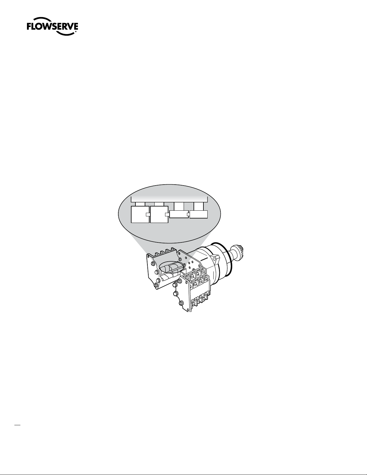
Figure 4.1 – Removal of the UEC-3 Electronic Controller 14
Figure 4.2 – UEC-3, MPC, DDC Assembly 17
Figure 5.1 – Encoder / MDPI / Transformer Installation 19
Figure 5.2 – Power / Interface Board Assembly 19
Figure 5.3 – Main Board Set Installation 20
Figure 5.4 – CSE Jumper Assembly 20
Figure 5.5 – CSE Control Station 20
Figure 5.6 – Controls Compartment Assembly 21
Figure 6.1 – UEX Local Control Panel 22
Figure 6.2 – Absolute Position Encoder 25
Figure 10.1 – Normal and Diagnostic Displays 35
Figure 14.1 – Default Configuration Guidelines 40
Figure 14.2 – Configuring the UEX Controller 40
Figure 15.1 – Standard Wiring Diagram for UEX Controllers 42
Figure 15.2 – DDC Wiring Diagram for UEX Controllers 43
Figure 15.3 – MOD APT Wiring Diagram for UEX Controllers 44
Figure 15.4 – Optional Features Wiring Diagrams 45
Figure 15.5 – Modbus, Foundation Fieldbus, Profibus DP V1, and Profibus PA, 46
and DeviceNet Network Wiring Diagrams
Figure 16.1 – Typical Modbus Network Wiring Diagrams – Single Loop 48
Figure 16.2 – Typical Foundation Fieldbus System with a DCS Host (Daisy Chain Shown) 50
Figure 16.3 – Typical Profibus System with a DCS Host (Daisy Chain Shown) 52
Table 1.1 – Standard Application Voltages with +/- 10% Nominal Range 5
Table 2.1 – Required Rating for External Wiring 7
Table 3.1 – Maximum Number of Drive Sleeve Turns for Standard Four-Gear 10
and Optional Five-Gear Limit Switches
Table 3.2 – Limit Switch Parts 11
Table 5.1 – UEX Parts List 21
Table 16.1 – Specifications for the Profibus Cable 51
Table 16.2 – Maximum Segment Length 51
Table 16.3 – Belden Cable Specifications 53
Table 16.4 – Total Cable Length Between Repeaters or Nodes 53
3
flowserve.com
Page 4

1
Limitorque UEX FCD LMENIM1205-03-AQ – 05/15
Introduction
1.1 Purpose
This Installation and Maintenance Manual explains how to install, setup, and maintain the UEX controller
for the L120-10, L120-20, and L120-40 actuators. Information on installation, operation, control
features, and maintenance is provided.
Contact Flowserve Limitorque if assistance is needed or preferred for installation, upgrading, or training
in the operation of the UEX.
1.2 User Safety
Safety notices in this manual detail precautions the user must take to reduce the risk of personal injury
and damage to the equipment. The user must read and be familiar with these instructions before
attempting installation, operation, or maintenance. Work should be performed by a qualified tradesman
who is familiar with the operation and maintenance of electric actuators. Failure to observe these
precautions could result in serious bodily injury, damage to the equipment, voiding of the warranty, or
operational difficulty.
Safety notices are presented in this manual in three forms:
c WARNING: Refers to personal safety. Alerts the user to potential danger. Failure to follow warning
notices could result in personal injury or death.
a CAUTION: Directs the user’s attention to general precautions that, if not followed, could result in
personal injury and/or equipment damage.
NOTE: Highlights information critical to the user’s understanding of the actuator’s installation and
4
operation.
Page 5
Limitorque UEX FCD LMENIM1205-03-AQ – 05/15
1.3 Product Description
The UEX is designed for use with the three-phase L120 electric actuators for weatherproof, explosionproof, and submersible applications. The UEX is field-retrofittable to replace existing UEC-3 controllers.
With state-of-the-art controls based on MX control technology, the UEX offers an expanded feature set
compared to the UEC-3.
Please refer to LMENIM2306 for detailed menu configurations
Table 1.1 Standard Application Voltages with +/- 10% Nominal Range
Design Voltage Application Voltage
230 VAC, 60 Hz, 3 ph 208/220/230/240 VAC, 60 Hz, 3 ph
460 VAC, 60 Hz, 3 ph 380/400/415/440 VAC, 50 Hz, 3 ph
380/440/460/480 VAC, 60 Hz, 3 ph
525 VAC, 50 Hz, 3 ph 525 VAC, 50 Hz
575 VAC, 60 Hz, 3 ph 550/575/600 VAC, 60 Hz, 3 ph
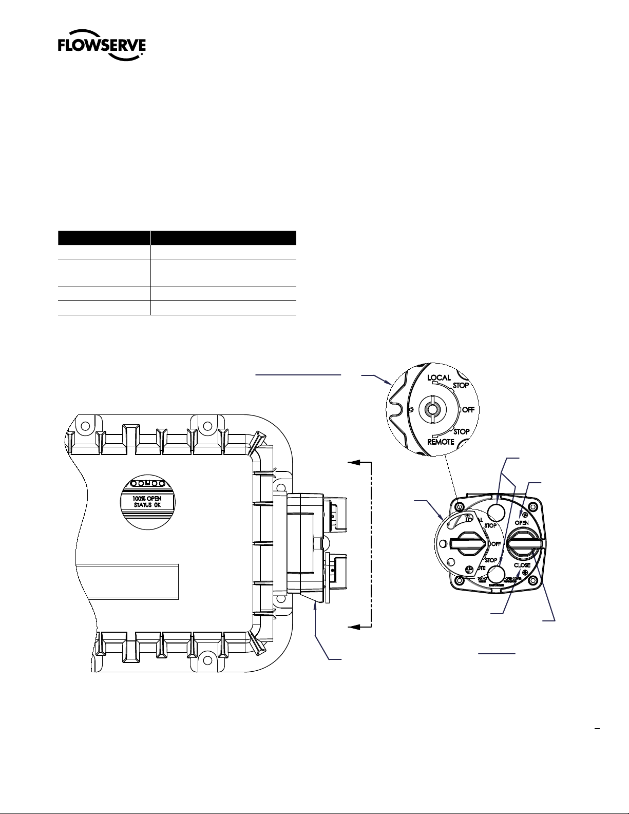
Figure 1.1 – UEX Local Control Panel
Selector Switch Detail
(Knob removed for clarity)
A
A
Blue
Knob
Close
(No)
Lights (2)
Open
(Yes)
Red
Knob
CSE Control
Station
VIEW A-A
5
flowserve.com
Page 6

2
Limitorque UEX FCD LMENIM1205-03-AQ – 05/15
Safety
2.1 Safety Precautions
c WARNING: Read this Installation and Maintenance Manual carefully and completely before
attempting to install, operate, or troubleshoot the Limitorque L120 actuator.
c WARNING: Be aware of electrical hazards. Turn off incoming power before working on the actuator
and before opening the switch compartment.
c WARNING: Potential HIGH-PRESSURE vessel – Be aware of high-pressure hazards associated with
the attached valve or other actuated device when installing or performing maintenance on your
L120 actuator. Do not remove the actuator mounting bolts when the actuator is mounted on a rising
stem valve unless the valve is in the FULLY OPEN position and there is NO pressure in the line.
c WARNING: Do not manually operate the actuator with devices other than installed Handwheel and
Declutch Lever. Using force beyond the ratings of the unit and/or using additive force devices such
as cheater bars, wheel wrenches, pipe wrenches, or other devices on the actuator Handwheel or
Declutch Lever may cause serious personal injury and/or damage to the actuator or valve.
c WARNING: Do not work on the actuator while it is mounted on a torque-seated valve.
6
Page 7

Limitorque UEX FCD LMENIM1205-03-AQ – 05/15
2.2 Safety Practices
The following checks should be performed to maintain safe operation of the L120 actuator.
• Mount motors on a horizontal plane, if possible.
• Keep the switch compartment clean and dry.
• Keep the valve stem clean and lubricated.
• Set up periodic operating schedule for infrequently used valves.
• Use a protective stem cover. Check valve stem travel and clearance before mounting covers on rising
stem valves.
• Verify all actuator wiring is in accordance with the applicable wiring diagram, national and local codes,
and Table 2.1.
Table 2.1 – Required Rating for External Wiring
Up to: Use wire rated at least:
40°C 60°C
60°C 75°C
flowserve.com
7
Page 8

3
Limitorque UEX FCD LMENIM1205-03-AQ – 05/15
Limit Switch & Torque Switch
Setting Procedures
3.1 Initial Actuator Preparation
Replace all molded plastic conduit and top protectors (installed for shipping purposes only) with pipe
plugs when installation wiring is complete.
3.2 Torque Switch
The torque switch is designed to protect the actuator in open and close directions.
a CAUTION: Disconnect all incoming power before opening limit switch compartment or working on
the torque switch.
• Do not use abrasive cloth to clean the contacts on the torque switch.
• Do not torque seat 90° operation valves nor run them against the stops. This may cause damage
to the valve.
NOTE: If the actuator has “torqued out,” release torque buildup by operating the actuator manually.
3.2.1 Setting Torque Switch
The torque switch was set at the factory according to customer-supplied information regarding necessary torque or thrust output that was provided at the time of the order. However, if the setting needs to
be adjusted, perform the following procedure:
a CAUTION: A torque switch limiter plate is provided on most actuators.
• Removal or modification of the torque switch limiter plate will void the actuator warranty.
8
• Do not exceed the setting indicated by this plate without contacting the Limitorque service
department.
Page 9
Limitorque UEX FCD LMENIM1205-03-AQ – 05/15
• Installing or adjusting the torque switch with the actuator in a loaded condition will result in a loss
of torque protection.
Item letters correspond to Figure 3.1.
1. Place the L120 actuator in manual mode.
2. Release the load on the wormshaft spring pack.
3. For open and close directions, loosen Screw (A) and move Pointer (B) to desired position. A higher
number indicates a high torque and/or thrust output.
4. Tighten Screw (A).
5. Operate the valve electrically to seat valve and to ensure tight shutoff.
6. Rebalance torque switch if required.
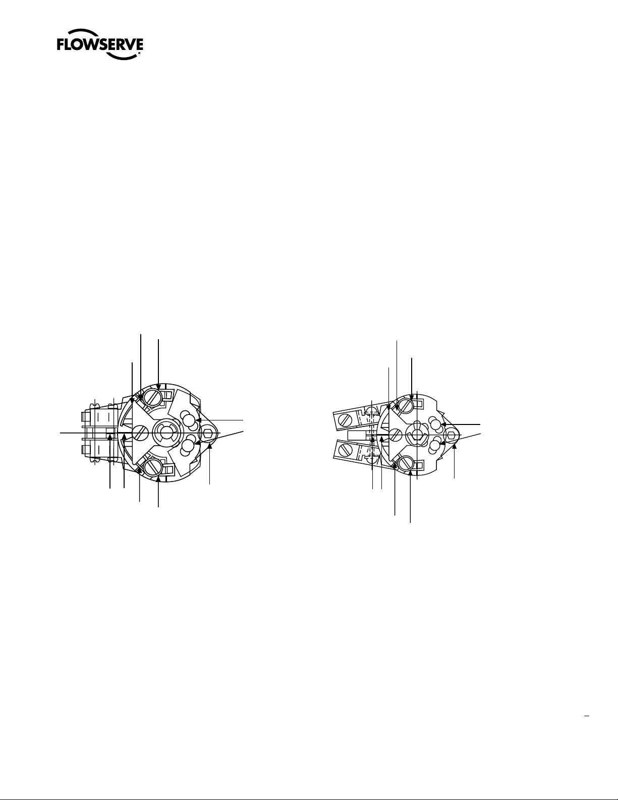
Figure 3.1 – Microswitch-Style Torque Switch and 600 Volt Torque Switch
B
Maximum Stop
Setting Plate
A
Maximum Stop
Setting Plate
B
A
OPEN
-10-20
Balancing
Screws
-10-20
CLOSE
Index Marks
B
A
Microswitch-Style Torque Switch
Mounting
Screw
Index Marks
600 Volt Torque Switch
3.2.2 Balancing Torque Switch
Item letters correspond to Figure 3.1.
1. Place the actuator in manual mode.
2. Remove the load from the wormshaft spring pack.
3. Note the open and close torque switch settings prior to reinstalling the torque switch.
4. Loosen Screws (A) and position both Pointers (B) at the #1 setting, tighten Screw (A). In this
position the index marks should be aligned.
Balancing
Screws
Mounting
Screw
B
A
9
flowserve.com
Page 10

Limitorque UEX FCD LMENIM1205-03-AQ – 05/15
5. Loosen balancing screws and install the torque switch. The base of the torque switch should be
flush against the compartment and the hole for the mounting screw should be aligned.
6. Install the mounting screw.
7. Tighten the balancing screws.
a CAUTION: The balancing screws should not be touched except during the balancing procedure.
The switch is now balanced and ready for the pointers to be returned to their original settings.
3.3 Geared Limit Switch
a CAUTION: The geared limit switch is not preset at the factory and must be adjusted after the
actuator has been mounted on associated equipment.
• Disconnect all incoming power to the actuator prior to opening the limit switch compartment and
adjusting the switch.
• Consult the relevant wiring diagram for limit switch contact development. All L120 units are
supplied with 16-contact limit switches - four switches on each of the four rotors. Two rotors are
used for end of travel indication. The remaining two rotors may be adjusted for any intermediate
point of travel.
• Do not use abrasive cloth to clean the contacts on the limit switch.
• Do not attempt to repair gearing in the limit switch. Replace entire gear frame assembly if
necessary.
10
3.3.1 Setting Limit Switch
Set the limit switch as follows. All item letters and piece numbers refer to Figure 3.2.
NOTE: See chart below for maximum number of drive sleeve turns for each unit size. The Intermediate
Shaft (B), shown in Figure 3.2, may take a considerable number of turns before rotor trip occurs.
Table 3.1 – Maximum Number of Drive Sleeve Turns for Standard Four-Gear and Optional Five-Gear
Limit Switches
Actuator Size Four-Gear Five-Gear
L120-10 630 6300
L120-20 740 7400
L120-40 640 6400
c WARNING: Potential Explosion Hazard. Do not use a variable speed electric drill for setting the limit
switch in an explosive environment.
a CAUTION: When setting the limit switch rotor segments (cams) using a variable speed electric drill,
do not run drill at speeds higher than 200 RPM. Operating the drill at high speeds can damage the
gearing within the limit switch.
Page 11
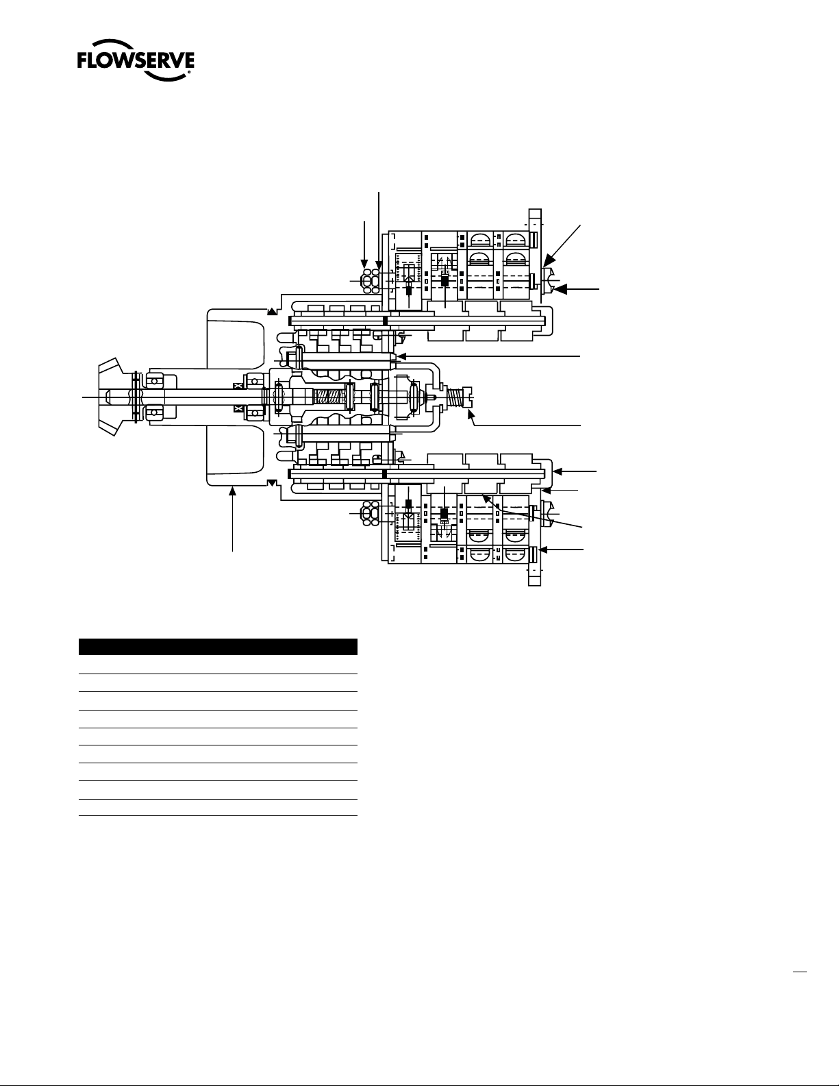
Figure 3.2 – Limit Switch
Limitorque UEX FCD LMENIM1205-03-AQ – 05/15
7
8
6
5
B
A
4
9
3
2
1
Table 3.2 – Limit Switch Parts
Piece Quantity Description
11 Gear Frame Assembly
22 Eight-Switch Contact Block Assy.
312Rotor Segment (short)
44 Rotor Shaft
54 Machine Screw
64 Flat Washer
74 Lock Washer
88 Hex Nut
94 Rotor Segments (long)
3.3.2 Setting Procedure (Refer to Figure 3.2)
1. Open the Controls Compartment Cover (refer to Figure 5.5).
2. Put the actuator into manual operation. Use the handwheel to operate the valve in the “open” direction. While operating the valve, note the direction of the Intermediate Shaft (B) corresponding to the
rotor or rotors to be set.
3. When the valve is fully open, close it one turn of the handwheel to allow for coast of moving parts
or refer to the valve manufacturer setting requirements.
4. Push in the Setting Rod (A) and turn one-quarter turn. The rod will latch in this depressed position.
11
flowserve.com
Page 12
Limitorque UEX FCD LMENIM1205-03-AQ – 05/15
5. Refer to the applicable wiring diagram for contact development. The limit switch contact is closed
when the rotor is engaged with the plunger. If the rotor to be set has not turned 90 degrees to
operate the plunger, turn the intermediate shaft in the same direction as noted in Step 2 until the
rotor clearly trips the switches. This rotor is now set correctly.
6. Before moving the valve, depress and turn the Setting Rod (A) one-quarter turn to the spring
released position. Insert a screwdriver into the intermediate shafts to ensure that they will not move.
a CAUTION: Do not operate the valve when Setting Rod (A) is in a fully depressed position. Loss of
contact setting will occur and the setting rod will be damaged.
7. Operate the valve by handwheel to fully “close” position; reverse direction by one turn of the handwheel to allow for coast of moving parts or refer to the valve manufacturer setting requirements.
8. Set the other rotors by following Steps 4 through 6.
Figure 3.3 – Setting the Open and Closed Contacts
Closed
position
Open
position
3.3.3 Combination of Contacts (Refer to Figure 3.2)
The rotor segments can be separated and rotated through 90 degrees to give various combinations of
normally open or normally closed contacts to each rotor.
1. Remove Nuts (piece 8) and Fillister Head Machine Screws (piece 5, for a total of two fasteners on
each side of the switch).
2. Remove complete contact assembly from the back plate.
3. Rearrange cams on the camshaft to produce the required combination of contacts.
4. Replace contact assembly on back-plate (ensuring that the registers fit correctly) and secure with
the machine screw and nuts.
12
5. Set limits according to the procedure above.
NOTE: For mechanical operation and maintenance of the L120 actuators, please see section 5 and 6 of
LMENIM1201.
Page 13

4
Limitorque UEX FCD LMENIM1205-03-AQ – 05/15
Removal of the UEC-3
Electronic Controller
NOTE: Confirm that the limit switches are set properly prior to disassembly and removal of the UEC-3
and related components. Confirming the settings will allow for installation of the UEX Electronic
Controller without requiring a reset of the limit switches.
1. Turn off the power to the actuator.
2. Open the Controls Compartment Cover.
3. Cut and remove all wire ties from wiring that is connected to the UEC-3 assembly (pc# C-201).
4. Disconnect the incoming power from the Interconnect Board.
5. Disconnect the Motor leads and Heater leads from the Interconnect Board.
6. Disconnect the Pushbutton Station ribbon cable from the Interconnect Board.
7. Disconnect the Analog-to-Digital Circuit Board (pc# C-223) ribbon cable from the Interconnect Board.
8. Disconnect the R/I circuit board (pc# C-210) ribbon cable
9. Uninstall the Potentiometer by removing the screws that fasten it to the MDPI assembly.
10. Uninstall the MDPI assembly by removing the screws that fasten it to the Geared Limit Switch
assembly.
11. Unplug the optional I/O Circuit Board (pc# C-223) from the SBC Board on the UEC-3 Assembly.
12. Label all customer wiring and disconnect from the Interconnect Boards.
13. Remove the four screws from the UEC-3 Assembly (pc# C-201) and carefully remove the Assembly
from the Controls Compartment.
14. Remove the Pushbutton Station with ribbon cable from the L120 gear housing conduit entry.
13
flowserve.com
Page 14
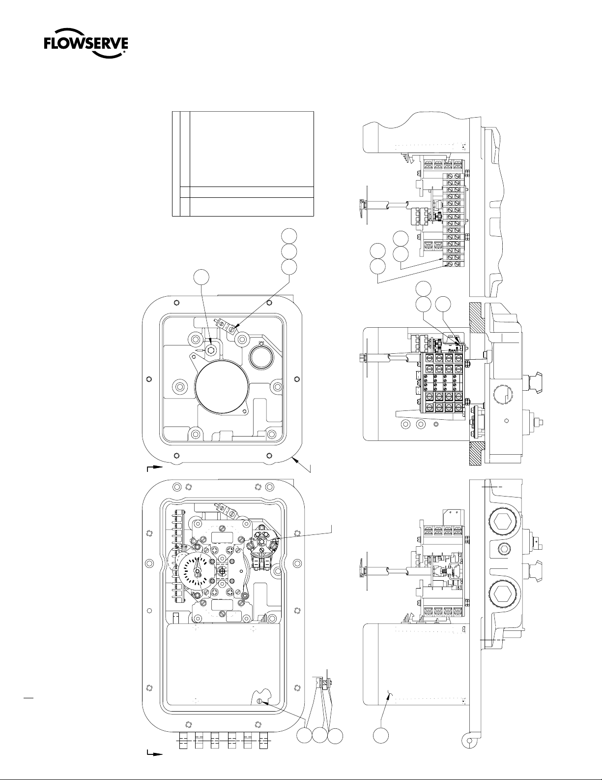
Figure 4.1 - Removal of the UEC-3 Electronic Controller
DESCRIPTION
TMI INTERGAL ITEMS
SCREW, PAN HD. MACH.
LOCKWASHER,EXT. TOOTH
GROUND LUG
UNIVERSAL ELECTRONICS CONTROLLER
1
C185 1C186
1
C201
SCREW,PAN HD.MACH.
4
C202
LOCKWASHER
4
C203
FLAT WASHER
12
C203-1
TERMINAL STRIP (12 POINT)
TERMINAL STRIP INSULATOR
1 4 4
1
C204
C204-1
SCREW,PAN HD.MACH.
C205
HEATER ASSY
QTY.
1
1
PC.
NO.
C184
C23
LOCKWASHER,EXT.TOOTH
C206
SIGNAL CONVERTER
SCREW,PAN HD.MACH.
1 4 4
C210
C211
SCREW, PAN HD. MACH.
BRACKET, TERMINAL STRIP
LOCKWASHER,EXT.TOOTH
2
1
C217
C216
C212
LOCKWASHER,EXT. TOOTH
2
C218
BRACKET
1 2 2
C220
SCREW,PAN HD.MACH.
C221
LOCKWASHER,EXT.TOOTH
C222
INTERFACE P.C. BOARD
1 2 2
C223
SCREW, PAN HD. MACH.
C224
LOCKWASHER,EXT. TOOTH
C225
Limitorque UEX FCD LMENIM1205-03-AQ – 05/15
UEC
PIFF ASSY
1
311
C
186
C
185
(HEATER)
C
23
(GROUND LUG)
C
184
C
-1
204
C
C
206
204
C
205
C
218
C
C
216
217
12C1111C1010C99C
12C1111C1010C99C
INT.1
INT.1
12
12
INT.2
INT.2
16
16
16C1515C1414C1313C
16C1515C1414C1313C
(GEAR LIMIT SWITCH AND OTHER ITEMS REMOVED FOR CLARITY)
AA
(TORQUE SWITCH)
E
S
O
L
-10-20
INT 1
INT 2
C
14
75
100
50
OPEN
PERCENT
0
25
OPEN
CLOSE
4 GEAR
L120-10
UEC UEC
UNIVERSAL
ELECTRONICS
CONTROLLER
(UEC)
X3
C
T 2
C
A
A
202
203
C
203-1
C
201
Page 15
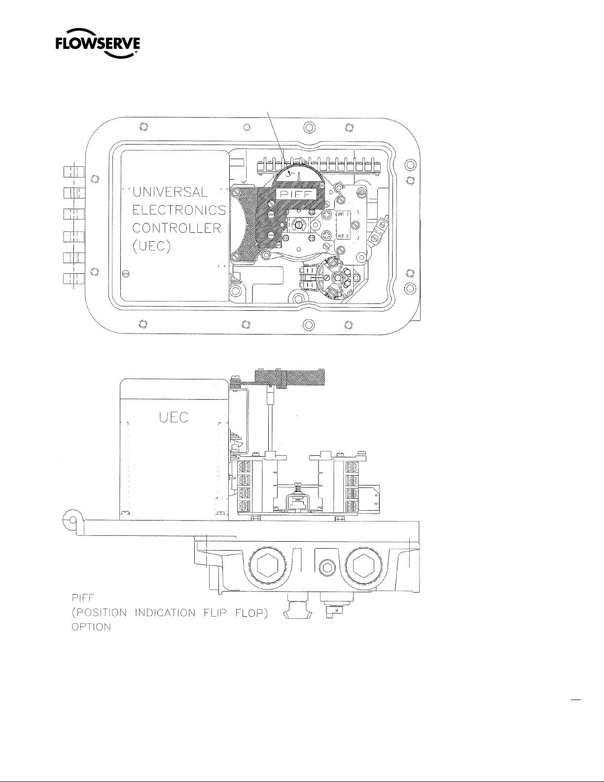
Figure 4.1 – Removal of the UEC-3 Electronic Controller (continued)
Limitorque UEX FCD LMENIM1205-03-AQ – 05/15
flowserve.com
15
Page 16
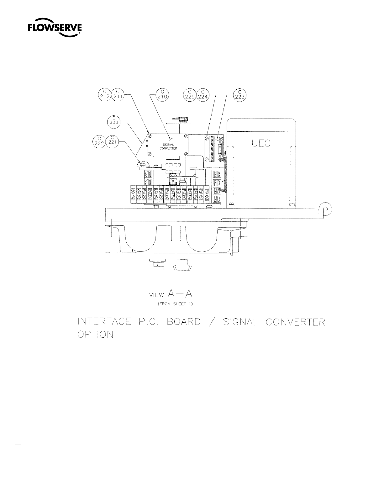
Figure 4.1 – Removal of the UEC-3 Electronic Controller (continued)
Limitorque UEX FCD LMENIM1205-03-AQ – 05/15
16
Page 17
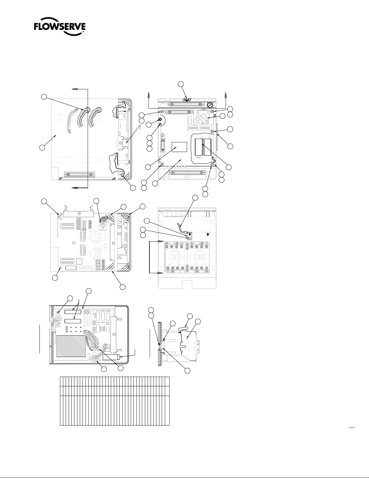
Figure 4.2 – UEC-3, MPC, DDC Assembly
Limitorque UEX FCD LMENIM1205-03-AQ – 05/15
11
23
17
INSULATOR BEHIND PCB
B-E ELEC
34
25
31
4
ON BOM 4805-455
PLASTIC COVER
7
A
31
25
35
RIBBON FOR SW93
30
25
26
ON CLEAR
20
31
9
25
22
8
37
29
c
B
SUPPLY
MOTOR
HEATER
B
3
21
A
FUSE
FUSE
25
28
13
32
15
36
1918
35
2
FUSES
6
12
SECTION A-A
c
24
27
10
14
1
VIEW C-C
FUSE
16
37
1
SCREW, PAN HD
5
15
16
31
1348351362
1
SCREW, PT FLAT
SCREW, PT OVAL HD
BITBUS/MODBUS PROM
SCREW, PAN HD
SCREW, PAN HD
SCREW, PAN HD
SCREW, PAN HD
1DDC/4 UEC
LOCKWASHER (INT TOOTH)
SCREW, PAN HD
2271291303
5DDC/4 UEC
1261
LOCKWASHER (INT TOOTH)
HEX NUT 25HEX NUT
24
1
1
2
LOCKWASHER (EXT TOOTH)
TERMINAL COVER, UEC
CONTROL BOX, UEC
FRONT COVER, UEC
21
22
23
28
33
32
14
1
1
1
1
SBC W/ CIRCUIT TRACE
RAIL, DIN
STICKER, UEC-3 ALL
HARNESS, CONTACTOR
10
12
11
13
1
1
1
INTERCONNECT BD (DDC SHOWN)
HARNESS, STARTER
MOV SNUBBER, 12A/25A
7
8
9
1
1
1
HARNESS, RIBBON 50PIN
BRACKET, TRANSFORMER
DAUGHTER BOARD (DDC ONLY)
17
18
19
20
1
1
1
1
INSULATOR, SBC
SCREEN PLATE
LABEL, FRONT COVER
INSULATOR, ICB
3
5
6
1
141
1
GROUND WIRE, POWER
HARNESS, POWER
HARNESS, HEATER
HARNESS, ICB TO D. BOARD
ITEM
1
2
QT Y.
1
1
REVERSING CONTACTOR
POWER SUPPLY BOARD
33
DESCRIPTION
17
flowserve.com
Page 18

5
Limitorque UEX FCD LMENIM1205-03-AQ – 05/15
UEX Electronic
Controller Installation
c WARNING: Turn off all incoming power before installing or working on the UEX Electronic Controller.
1. Install the MDPI Gearing Assembly (pc# 2-1) to the Geared Limit Switch Mounting Plate using the
two Socket Head Cap Screws (pc# 2-1-12, 2-1-13). (See Figure 5.1)
2. Install the Transformer/Bracket Assembly (pc# 2-2, 2-9) to the Geared Limit Switch using the six
10-32 Pan Head Screws (pc# 2-11). (See Figure 5.1)
3. Connect the Primary leads (L1 & L2) and the Secondary leads (H1 & H2) to the matching terminals
on the Terminal Strip (pc# 3-5). (See Figure 5.2)
4. Install the Power/Interface Board Assembly using the five Socket Head Cap Screws (pc# 3-6).
(See Figure 5.2)
5. Connect the Power Board leads L1, L2, and L3 to the mating terminals on the Terminal Strip.
(See Figure 5.6)
6. Connect the Power Board Motor leads T1 to T3 on the Terminal Strip. Connect T2 to T2 on the
Terminal Strip and connect T3 to T1 on the Terminal Strip. (See Figure 5.6)
a CAUTION: Ensure that wire connections are as described in Step 6 to prevent incorrect rotation.
7. Install the Encoder/Bracket Assembly onto the Transformer Bracket using the three Panel Fasteners.
(See Figure 5.1)
8. Remove the Sight Glass Retention Plate from the Controls Compartment Cover. This part will not
be reused.
18
NOTE: Retain the sight glass and hardware for use in the following step.
9. Install the Main Board Assembly Bracket (pc# 1-1) into the Controls Cover using the four screws
(pc# 204-4) previously used to mount the Sight Glass Retention Plate. (See Figure 5.3)
10. Connect the Main Board Interconnect Harness to the Main Board Assembly (pc# 1-2) and then to
the Interface Board (pc# 3-3). (See Figures 5.2 & 5.3)
Page 19

Limitorque UEX FCD LMENIM1205-03-AQ – 05/15
11. Connect the Encoder Board Harness (pc# 2-4) to the Main Board J-1 (pc#1-2). (See Figures 5.1 & 5.3)
12. Install the Main Board Assembly (pc# 1-2), with option boards (pc# 1-3) if supplied, using four Pan Head Screws
(pc# 1-4). (See Figure 5.3)
13. Connect the existing UEC-3 Harness to the Interface Board (pc# 3-3). (See Figure 5.2)
14. Install the O-Ring onto CSE Control Station (pc# 3-7) and slide the CSE into the Controls Compartment Cover.
15. Connect the CSE Ribbon Cable to the Interface Board (pc# 3-3). (See Figure 5.2)
16. Connect the 120V cable from the Main Board Interconnect Harness to the Terminal Strip. (See Figure 5.6)
17. Attach one UEX identification label (pc# 3-8) in between the feet of the interface board bracket (See Figure 5.2).
Attach one UEX identification label to the left of the existing unit nameplate on the gearbox.
Figure 5.1 - Encoder / MDPI / Transformer Installation
Figure 5.2 - Power / Interface Board Assembly
19
flowserve.com
Page 20

Figure 5.3 - Main Board Set Installation
201
-1
204
-3
204
-1
204
-6
Limitorque UEX FCD LMENIM1205-03-AQ – 05/15
204
-4
1-2
Figure 5.4 - CSE Jumper Assembly
1-1
1-3
ASSEMBLY VIEW
1-4
20
Figure 5.5 - CSE Control Station
Controls
Compartment
Display
Window
3-7
3-7
-4
3-7
-25
3-7
-24
ASSEMBLY VIEW
Page 21

Figure 5.6 - Controls Compartment Assembly
Option Boards
MDPI Gearing
Control
Station
Display
Window
Main LCS Board
Encoder
Assembly
Power / Interface
Board Assembly
Compartment
Cover
Limitorque UEX FCD LMENIM1205-03-AQ – 05/15
Table 5.1 – UEX Parts List
ITEM NO. QTY. DESCRIPTION
1-1 1 MOUNTING BRACKET, MAIN BOARD SET
1-2 1 MAIN LCS BOARD
1-3 3 (max) OPTIONAL BOARDS
1-4 4 MACHINE SCREW
2-1 1 MDPI GEARING ASSEMBLY
2-1-12 2 SOCKET HEAD CAP SCREW
2-1-13 2 LOCKWASHER
2-2 1 TRANSFORMER BRACKET
2-3 1 ENCODER MTG BRACKET
2-4 1 ENCODER ASSEMBLY
2-9 1 TRANSFORMER ASSEMBLY
2-10 (6) HEX NUT
2-11 6 PAN HEAD MACHINE SCREW
2-12 1 GEARED LIMIT SWITCH ASSEMBLY
2-13 1 HEATER ASSEMBLY
3-1 1 POWER BOARD ASSEMBLY
ITEM NO. QTY. DESCRIPTION
3-2 1 POWER / INTERFACE BOARD CHASSIS
3-3 1 INTERFACE BOARD ASSEMBLY
3-5 1 TERMINAL STRIP ASSEMBLY
3-6 5 SOCKET HEAD CAP SCREW
3-7 1 CONTROL STATION
3-7-4 1 O-RING
3-7-24 4 SOCKET HEAD CAP SCREW
3-7-25 4 LOCKWASHER
3-8 1 LABEL
201-1 1 COMPARTMENT COVER
202 1 ELECTRICAL COMPARTMENT MTG PLATE
204-1 1 DISPLAY WINDOW
204-3 1 O-RING
204-4 4 HEX HEAD SELF-TAPPING SCREW
204-6 1 GASKET
Note: Items in parentheses are not shown
21
flowserve.com
Page 22

6
Limitorque UEX FCD LMENIM1205-03-AQ – 05/15
Standard Control Features
6.1 Basic Specifications
The standard UEX controller wiring diagrams are shown in Section 15. Optional wiring diagrams are on
subsequent pages. The most current wiring diagram is provided with the product.
The following control features are included in the basic UEX controller.
For Optional Features, please refer to Section 8-Optional Control Features.
Figure 6.1 – UEX Local Control Panel
Selector Switch Detail
(Knob removed for clarity)
A
Blue
Knob
Lights (2)
Open
(Yes)
22
A
CSE Control Station
Close
(No)
VIEW A-A
Red
Knob
Page 23

Limitorque UEX FCD LMENIM1205-03-AQ – 05/15
6.2 Local Control
The Control Panel includes a red Local/Stop/Remote selector switch (padlockable in all three positions;
a ¼" (6 mm) hasp is recommended) and a black Open/Close rotary switch (spring-return to center). The
Open and Close switches may be configured to allow either push-to-run (inching) control or maintained
control.
Local Indication
The Control Panel includes the following:
• 32-character graphical LCD
Displays valve position as “PERCENT OPEN” and the current actuator status.
• Red/Green LED Indicators – the color assignment for the red and green LEDs is reversible as
standard.
Red ON = Valve fully open
Red “BLINKING” = Valve opening
Green “BLINKING” = Valve closing
Green ON = Valve fully closed
• Yellow LED
Yellow ON = Actuator available for remote operation,
= Valve stopped in Intermediate position.
Yellow “BLINKING” = Monitor Relay de-energized, actuator not available for remote operation.
6.3 Remote Control Modes of Operation
The actuator may be controlled remotely by two, three or four wires.
• Four-Wire Control – Three momentary contacts. Valve can be opened, closed or stopped.
• Two-Wire Control – Single open or closed contact. Valve can be opened or closed, but not stopped in
mid-travel.
• Three-Wire Maintained – Two momentary contacts for self-maintained control. Valve can be opened
or closed but not stopped in mid-travel.
• Three-Wire Inching – Two “push-to-run” contacts. Valve can be opened, closed and stopped in
mid-travel.
Refer to Figure 15.4 for remote wiring connections.
flowserve.com
23
Page 24

Limitorque UEX FCD LMENIM1205-03-AQ – 05/15
Remote Control Type
The actuator may be placed in digital only, modulation only, network only, or multi-command types.
• Digital (Discrete) Only Control Type – Only digital input commands are recognized and acted upon.
All other types of remote control commands are ignored.
• Analog (Modutronic) Only Control Type – Only Modutronic 4-20 mA commands are recognized and
acted upon. All other types of remote control commands are ignored.
• Network Only Control Type – Only network (DDC, Fieldbus, Profibus, Device Net) commands are
recognized and acted upon. All other types of remote control commands are ignored.
• Multi-control Mode Operation - there are three modes of remote control when remote mode is
configured for multi control: digital control, analog control, and network control. Digital and network
control operation is based on the last command received. Analog operation is initiated by either
toggling user input 2 (configure for CSE input) or breaking and reapplying the analog control.
Remote Control Signal Power
Power for remote control signals may be derived internally from the actuator or provided externally by
the user. Signals can range from 24 to 125 VAC or VDC.
External Power Supply
An external power supply in the range of 12 to 24 VDC may be provided by the user with the optional
UPS board.
Standard Internal Power Supply
The standard internal signal supply is 24 VDC. The 24 VDC supply offers a maximum loading of 5 W.
The 24 VDC supply, in conjunction with the opto-isolated digital inputs, allows control from remote voltfree contacts over long distances and simplifies the user’s control scheme. Standard control employs a
negative earth. Positive earth (negative switching) is available by wiring to the (+) positive common as
shown on the wiring diagrams.
6.4 Emergency Shutdown (ESD)
Up to three independent ESD signals may be applied, prioritized and configured for different actions
for the ESD event associated with each. Either of these ESD signals may be applied to the actuator
to override any existing command signal and send the valve to its preselected shutdown position,
providing the actuator is in Remote mode (default configuration for ESD is “Ignore, take no action”).
Any new command signal will be ignored until the ESD signal is removed. During setup, the actuator
may be configured to close, open, stop, take no action, or “move to a previously configured position” on
receipt of the ESD signal. The ESD action may also be configured to override any inhibit signal, the local
selector switch, the local stop switch, an overtorque condition, lost phase, or jammed valve protection.
Motor thermal protection may be bypassed for critical ESD applications in non-hazardous or special
service locations. Disabling the motor thermostat voids all third-party certifications, including Factory
Mutual and CSA.
24
Page 25

Limitorque UEX FCD LMENIM1205-03-AQ – 05/15
6.5 Remote External Interlocks/Inhibits
Three user-defined inputs are provided for the connection of remote contacts that will prevent motorized operation of the actuator. These are effective in both Remote and Local modes and may only be
overridden by a maintained ESD signal, if so configured (refer to Figure 15.1 for wiring connections).
For ESD connections, the user may select either a single common or isolated commons.
6.6 Absolute Position Encoder
An absolute position encoder, incorporated into the L120 actuators, is the same as the encoder used in the
MXa. It includes 18 phototransistors that are switched on and off by a gear/wheel mechanism.Valve position
is sensed by an 18-bit, optical, absolute position encoder with redundant position sensing circuits designed
for Built-In Self-Test (BIST).
Each of the position sensing circuits is redundant, facilitating BIST. The BIST feature discerns which
failures will signal a warning only and require a warning plus safe shutdown of the actuator. Open and
closed positions are stored in permanent, nonvolatile memory. The encoder measures valve position at
all times, including both motor and handwheel operation, with or without power present, and without the
use of a battery. The absolute encoder is capable of resolving ±7° of output shaft position and over 10,000
output drive rotations, however, in the L120, the encoder is limited to the maximum geared limit switch
travel. Refer to Table 3.1.
This design permits continuous monitoring of valve position during motor and handwheel operation. The
encoder is 100% repeatable and requires no backup power source for operation. The output is used to
control the open and closed valve position and measure and report valve position, as well as provide local
and remote position feedback.
The positioning accuracy is better than 99% for valves requiring 50 or more turns. For the maximum
actuator turns and resolution, see Table 3.1.
Figure 6.2 – Absolute Position Encoder
18-bit optical, redundant position
encoder provides continuous valve
position monitoring without battery
backup with Built-In Self-Test (BIST)
capabilities.
flowserve.com
25
Page 26

7
Limitorque UEX FCD LMENIM1205-03-AQ – 05/15
Protection Features
7.1 Autophase Protection and Correction
The phase rotation of the incoming three-phase supply is continuously monitored. In the event that field
wiring is reversed, UEX controls automatically correct to ensure the valve operates in the commanded
direction. In addition, the detector circuit monitors the presence of all three phases. If a phase is lost,
valve starting will be prevented and the user alerted via an LCD error message and Monitor Relay Alarm.
7.2 Jammed Valve Protection
If the actuator cannot overcome the required valve starting torque, a jammed valve condition occurs.
Jammed valve protection senses the lack of valve movement and initiates a brief reverse/forward cycle
to free the valve. If this is unsuccessful, further electrical operation is prevented and the monitor relay is
signaled.
7.3 Instantaneous Reversal Protection
The control logic incorporates a brief time delay (from 0.5 to 1.0 seconds) between motor reversals.
This reduces motor current surges and prolongs the life of the contactor. Note: It is not necessary to
switch to STOP before reversing the actuator.
7.4 Motor Thermal Protection
The motor is protected against overheating by a thermal OL in the motor enclosure. Thermal cutout
threshold is set for 120˚C (Class B). Options are available for other classifications.
26
a CAUTION: Confirm that motor thermals are rated no higher than 120°C for Explosionproof service.
Page 27

8
Limitorque UEX FCD LMENIM1205-03-AQ – 05/15
Optional Control Features
8.1 Modutronic
The Modutronic controller will alter valve position in proportion to an analog command signal. It
includes an automatic pulsing mode to reduce overshoot at the set point.
The following parameters may be easily set during the configuration of the unit:
• Proportional Band range from 2% to 100% (15% = default)
• Dead Band range from ± 1% to 50% (2% = default)
• Polarity 20 mA = OPEN (default) or 20 mA = CLOSE
• Action on loss of command signal OPEN, CLOSE, STOP (CLOSE = default), or Move-to a previously
configured position
• Delay after stop 0–60 seconds (0 = default)
• Command Signal
• 4–20 mA
• Input impedance - 150 ohms
Repeatability – The Modutronic is repeatable to within ±1 % for 60 seconds stroke time or longer,
and 2% for 30 to 60 seconds.. Repeatability is defined as encoder feedback position versus position
command. Overall valve and actuator system accuracy depends on many factors, including actuator
gearing backlash and valve/actuator coupling tolerance, and therefore cannot be defined by this
document.
Extrema Mode – If the command signal represents a position of 0–2% OPEN (nominal 4.00–4.32 mA)
or 98–100% OPEN (nominal 19.68–20.00 mA), then the UEX/L120 will move the valve directly to that
position, without pulsing.
Positioning Frequency – The standard frequency is suitable for a rate of 600 starts/hour for short
periods, typical of process start-up. Typical process control of ≤ 100 starts/hour.
27
flowserve.com
Page 28

Limitorque UEX FCD LMENIM1205-03-AQ – 05/15
8.2 Analog Position Transmitter (APT)
The APT is an internally powered, non-contacting valve position transmitter. The isolated output signal
is proportional to the position of the valve and is available as 4–20 mA and/or 0-20 mA, 0-10 VDC, 2-10
VDC, 0-5 VDC, or 1-5 VDC.
The user may select the minimum signal to represent either the fully OPEN or the fully CLOSE position
of the valve during the setup procedure.
• Accuracy = 99% of full scale value (for Drive Sleeve Turns > 50)
• Non-Linearity = ± 1% of full scale value
• Impedance = 0–600 ohms (4–20 mA signal)
• Minimum external load = 1000 ohms (0–10 VDC signal)
8.3 Two-Speed Timer
A two-speed pulsing timer can be enabled to extend the operating time in the close and/or the open
directions. Pulsing may be applied from 0.5 (if precision is set to xxx.x%) to 99% of full valve travel or
to a small portion. The ON pulsing cycle is configurable from 0.5 to 20 seconds in 0.5 second increments, and the OFF pulsing cycle is configurable from 1.0 to 200 seconds in 1 second increments. The
two-speed timer is especially effective where concerns of hydraulic shock exist.
28
8.4 Control Station (CSE)
The CSE is a separate control station designed for the operation of inaccessible actuators. It is available
with LEDs, Remote/Local and Open/Close selector switches. The CSE may be powered by the actuator
internal supply, provided wire resistance and other external loads do not limit the available signal power
presented to the UEX.
Page 29

9
Limitorque UEX FCD LMENIM1205-03-AQ – 05/15
Network Communications
The UEX provides a comprehensive network option portfolio to the user. Network solutions are improved
for the user that has an L120 with UEC, with the addition of DeviceNet to complement Modbus,
Fieldbus H1, Profibus DP_V1 and Profibus PA. UEX provides the user with predictable, reliable, and safe
operation for years to come, in applications which are subject to the most rigorous requirements and
environmental extremes.
With each of the provided network protocols a user may configure the unit to move to a predefined
fail-safe position on loss of communication. Action on loss of command signal OPEN, CLOSE, STOP, or
MOVE-TO preconfigured position. The user may also configure the length of time communication must be
lost before the unit indicates communication loss and performs the communication loss action.
9.1 Modbus
Modbus™ provides the ability to control and monitor up to 250 actuators over a single twisted-pair
cable. The communication network employs Modbus
dant. Redundancy assures that any single break or short in the communication cable will not disable
any actuators. Each actuator has included an addressable field unit that communicates over the twisted
pair network and executes open, close, stop, ESD, and GO TO position commands. The field unit
also communicates all actuator status and alarm diagnostic messages over the same communication
network.
Modbus Network
• Single-ended loop (as standard – See Figure 16.1)
• Modbus protocol
• High speed – up to 19.2K baud
™
™
protocol on an RS-485 network and is redun-
Foundation
flowserve.com
29
Page 30

Limitorque UEX FCD LMENIM1205-03-AQ – 05/15
9.2 Master Station III
L120 actuators equipped with Modbus can be controlled via Flowserve Limitorque’s Master Station II or III.
The next-generation master station is designed specifically for use with Limitorque’s line of DDC
(Modbus) electric actuators. The Master Station III acts as a single-source controller for up to 250
actuators.
The Master Station III is a plug-and-play solution that provides complete control and diagnostics for
Limitorque field units through a simple touch-panel operator interface. The key features of the Master
Station III include:
• A network time protocol to allow for time synchronization of alarms/diagnostic data to Host device
• Multilingual support includes English, Spanish, German, French, Italian
• Asset management and diagnostic via Bluetooth V2.0+ Enhanced Data Rate (EDR) Class 100m
• Configuration of slave register polling schedule
• Industry standard Modbus RTU, ASCI, UDPor TCP/IP protocols
• Three levels of user password protection
• 5.6” TFT touch-screen display
• E-mail notification of configurable alarm conditions
• Data/event logging
• Network control of up to 250 devices
• Front access to peripheral ports: Ethernet, USB x 2, VGA, printer/debug
• Modular hot-swappable redundant design
• Built-in secure Web server for control, monitoring and asset management capabilities
30
9.3 Foundation Fieldbus Communication
L120 actuators can be fitted with Foundation Fieldbus protocol that complies with the IEC 61158-2
Fieldbus H1 standard. The field unit device is able to support several topologies, such as, point-to-point,
bus with spurs, daisy chain, tree, or a combination of these. The FF device has network features that
include:
• Link Active Scheduler that controls the system
• High-speed communications at to 31.25 kbits/sec
• Publisher - subscriber communication
• One analog input block, one analog output block, two discrete output function blocks, Transducer
block, Resource block, and four discrete input function blocks
• PID (proportional integral derivative) loop control
• Device descriptions
• Configurable by user
Link Active Scheduler communication: Fieldbus segments have one active Link Active Scheduler (LAS)
at a given time, which is the bus arbiter, and does the following:
Page 31

Limitorque UEX FCD LMENIM1205-03-AQ – 05/15
• Recognizes and adds new devices to the link
• Removes non-responsive devices from the link
• Schedules control activity in, and communication activity between, devices
• Regularly polls devices for process data
• Distributes a priority-driven token to devices for unscheduled transmissions
9.4 PROFIBUS DP V1 Communication
L120 actuators can be fitted with Profibus DP_V1 protocol field units that comply with EN50170
Fieldbus Standard for RS-485 communications. The device supports several topologies, such as,
point-to-point, bus with spurs, daisy chain, tree, or a combination of these. The PB device has network
features that include:
• High-speed communications up to 1.5 m/bits/s
• Master-to-slave communication
• One analog input block, one analog output block, two discrete output function blocks, Transducer
block, Physical block, and four discrete input function blocks
• Device descriptions configurable by user
High-Speed Data Exchange – Startup Sequence
• Power ON / Reset – Power On / Reset of master or slave
• Parameterization – download of parameters into field device (selected during configuration by the
user)
• I/O Configuration – download of I/O configuration into the field device (selected during configuration
by the user)
• Data Exchange – cyclic data exchange (I/O Data) and field device reports diagnostics
• Also supports Profibus_DP redundancy
9.5 PROFIBUS PA Communication
A Profibus PA protocol is available and complies with EN50170 Fieldbus Standard and Fieldbus physical
layer per IEC 61158-2 for communications. The device supports several topologies, such as point-topoint, bus with spurs, daisy chain, tree, or a combination of these. The PB device has network features
that include:
• High-speed communications at to 31.25 kbits/s with Manchester coding
• Master-to-slave communication
• Bus powered for 9-32 VDC and 15 mA per actuator
• Stand-by communication channel
• One analog in and one analog out, four digital input and up to eight digital output function blocks
• Device descriptions configurable by user
31
flowserve.com
Page 32

Limitorque UEX FCD LMENIM1205-03-AQ – 05/15
9.6 DeviceNet
DeviceNet complies with CAN based protocol and provides the following features:
• DeviceNet Group 2 Server implementation.
• Bus Powered Network Interface allows power alarm information to be communicated when actuator
loses main power. The actuator does NOT drop off the network when 3-phase power is lost.
• Standard Polled I/O Connection
• Standard Bit Strobed I/O Connection
• Standard Change of State / Cyclic I/O Connection
• Standard explicit connections defined as:
• Various Assembly Objects and sizes that allow the network user to determine how much data to
transfer to accommodate network installation data throughput requirements.
• Automatic BAUD rate detection.
• Node Address configurable via local setup menu, or via the remote network user.
• Broadcast or group network originated ESD support.
The following commands and information may be transmitted over the DeviceNet network:
• “OPEN,” “STOP,” and “CLOSE” commands
• “ESD” and “MOVE–TO” position commands
• Actuator status and alarm messages
• Four digital inputs, two digital outputs, one analog input and one analog output for user configuration
• A surge-protected and isolated communication channels
• UEX control panel configuration
Please see Section 16 for network connection topologies and cabling recommendations.
32
Page 33

10
Limitorque UEX FCD LMENIM1205-03-AQ – 05/15
Monitoring and
Diagnostic Features
10.1 Local Features
LCD Displays – The LCD displays an array of data concerning the status of actuator components
in clear, graphical or textual language. The UEX is available with eleven languages:
English, Spanish, German, French, Italian, Portuguese, Mandarin, Russian, Bahasa
Indonesia, Turkish and Katakana.
Normal Display – The normal display illustrates current valve position and status.
Alarm Functions – Alarm functions (active alarms will be toggled every four seconds)
that may be displayed include:
• Valve Jammed - Valve cannot start moving
• Lost Phase - One of three phases lost
• Motor Overtemp – Thermal overload exceeded
• Overtorque - Torque exceeded in mid-travel
• Hardware Failure - Indication
• Modbus, Profibus,
• ESD Active - ESD signal active
• Inhibit Active - Inhibit signal present
• No analog signal - 4–20 mA signal absent (Modutronic enabled, red selector switch in
“REMOTE”)
• DDC, PB, FF, DNet comm. Loss – Enabled, signal absent
• Analog Output Loss - Enabled, but output current loop open
Foundation Fieldbus, DeviceNet off - Enabled, but “OFF”
33
flowserve.com
Page 34

Limitorque UEX FCD LMENIM1205-03-AQ – 05/15
10.2 Diagnostics
Standard Diagnostic Screens – Diagnostic screens may be accessed quickly through the Setup
dialogue or the UEX Dashboard Software solutions package. These screens provide detailed data of
actuator status. Included are:
• Hardware – status of electronic components such as thermistor, encoder, power board, DDC/FF/
PB/DeviceNet network board, analog board, DIGIN and ANIN (digital in and analog in)
• Motor – Phase rotation
• Power Supply – Maximum and minimum voltage, frequency
• Identification – Tag number, serial number, order number, software revision
• View Network Status – Checks for Standby, Recoverable Fault, Nonrecoverable Fault, and View
Network Status
• Operation Log – Actuator turns, contactor operations, motor run-time, stroke time, manual
operations
• View Control Compartment Temperature (View Power Supply Menus)
34
Page 35

Figure 10.1 – Normal and Diagnostic Displays
Normal Display - STATUS OK conrms that the actuator
is suitable for remote operation.
50% OPEN
STATUS OK
Limitorque UEX FCD LMENIM1205-03-AQ – 05/15
Normal Display/Alarm Condition - If the actuator is not suitable
for remote operation, the appropriate alarm will be shown.
50% OPEN
MOTOR OVERTEMP
Diagnostic Display informs user of failed hardware.
ENCODER
(FAULT) NEXT?
Typical Display
flowserve.com
35
Page 36

Remote Indication Features
11
Limitorque UEX FCD LMENIM1205-03-AQ – 05/15
11.1 Actuator Status Contacts
(S1a, S1b, S2a, S2b)
Four latched contacts provide remote feedback of actuator status. Two (S1a, S2a) contacts may be
individually configured for normally open, normally closed, or blinker (continuous opening and closing
of the valve) operation and provide feedback of one of the functions listed below. Two other relays are
complementary.
• Closed • Motor overtemp
• Closing • Overtorque
• Mid-travel • Open torque switch
• Opening • Close torque switch
• Open • ESD signal
• Stopped • Open inhibit
• Valve moving • Close inhibit
• Local selected • Lost phase
• Local STOP/OFF • No analog signal
• Manual operation • Hardware failure
• Valve jammed • Network controlled
• Remote selected • CSE controlled
36
Page 37

Limitorque UEX FCD LMENIM1205-03-AQ – 05/15
Recommended settings are:
• S1a – Normally closed contact at valve fully CLOSE
• S1b – Normally closed contact at valve fully OPEN – Default position. See wiring diagram.
• S2a – Normally open contact at valve fully CLOSE
• S2b – Normally open contact at valve fully OPEN – Default position. See wiring diagram.
The standard contacts are rated for 2.0 A at 30 VDC and 0.5 A at 125 VAC.
11.2 Monitor Relay (RM)
The monitor relay provides immediate indication of problems that prevent remote valve operation. It has
a normally open contact and a normally closed contact (1 x SPDT contact) and is energized when the
three-phase supply is present and the actuator is in a normal/healthy state.
The relay will de-energize if any of the following events occur:
• Loss of one or more phases of the three-phase power supply
• Loss of internal control supply
• Jammed valve detected
• Motor overtemp is active (unless thermostat is configured to OFF)
During configuration, the following parameters may be added to the monitor relay function:
• Selector switch is in “Local” mode
• Selector switch is in “Stop” position
• Overtorque
• Inhibit signal active
• ESD signal active (The user can enable or disable “local” mode and “stop” position. Default is
enabled.)
The monitor relay resets when the faulty state is rectified. The standard contacts are rated for 5.0 A at
250 VAC, 30 VDC. The monitor relay can be disabled if the user chooses.
11.3 Exact End Position Indication
On torque-seated valves, the end-of-travel indication switch trips when the required torque is achieved
at the end of travel. This ensures that remote, self-latched signals will not be disconnected prematurely,
and that the valve will be tightly seated.
flowserve.com
37
Page 38

12
Limitorque UEX FCD LMENIM1205-03-AQ – 05/15
Auxiliary Power Supply Uninterruptible Power Supply
(UPS) Connection
Isolated Commons
13
If the main three-phase power supply is not available during the configuration of the actuator, an optional
module contains provisions for connecting a 24 VDC, 1 A power source to the auxiliary input terminals
shown in the wiring diagram on the following pages. Power supply will draw up to 0.5 A.
The UEX is provided with isolated commons for control functions. Please refer to wiring diagram in
Section 15 for locations.
38
Page 39

Actuator Configuration
14
Limitorque UEX FCD LMENIM1205-03-AQ – 05/15
14.1 Local Configuration
UEX controllers may be configured through the CSE control station switches, with settings visible on the
LCD display. Settings that can be initiated or changed include:
• Direction of rotation
• Action on ESD
• External inhibits
• Remote control operating mode
• Motor thermostat action
• Stop valve on torque or position
• All optional features (Modutronic, Modbus, FF H1, PB-DPV1, PB-PA, DeviceNet, Timers, APT, etc.)
14.2 Default Configuration
Unless otherwise specified, UEX controllers will be shipped with the following configuration, which
becomes effective after the L120 limit switches are properly set.
• Open stop by limit
• Close stop by limit
• Maintained local controls
• Clockwise to close
• ESD is “off” and set to “IGNORE.”
• Inhibits enabled, turned “OFF”
• Remote control – three-wire maintained and Multi-mode
• Password – 100
• Modutronic Option (if installed)
39
flowserve.com
Page 40

Figure 14.1 – Default Configuration Guidelines
Limitorque UEX FCD LMENIM1205-03-AQ – 05/15
Modutronic Option
Proportional band – 15%
Deadband – 2%
Polarity – 20 mA = Open
Action on loss of signal = Close
FF Option, DeviceNet and PB
Option
Analog scale = 0-100
Proportional band – 15%
Deadband – 2%
Figure 14.2 – Configuring the UEX Controller
Modbus RTU protocol
9600 baud
Analog scale = 0-100
Proportional band – 15%
Deadband – 2%
Offset – 0 mA
1 Place selector switch in "STOP." The LCD
display will read "% OPEN" and "STATUS OK."
Operate the selector switch to the (YES) (NO)
0% OPEN
STATUS OK
(YES) positions. The message "SETUP?" will
be displayed for 10 seconds. Answer "YES" to
enter setup routine.
OPEN
(YES)
CLOSE
(NO)
40
2 All parameters may be congured by
KNOB IN
OPEN (YES)
POSITION
50% OPEN
TORQUE VALUE
answering "YES"/"NO" questions. For
example, entering a "NO" response to the
displayed screen will change the displayed
torque value. Select "YES" when the desired
value is displayed.
Configuration screens are displayed in English. Languages such as Spanish, French, German, Italian,
Portuguese, Mandarin, Russian, Bahasa Indonesia, Turkish and Katakana are also available and can be
configured via the actuator control panel.
A three-digit numeric password is included as part of the initial setup procedure to prevent unauthorized
changing of the configured parameters. If the password is entered incorrectly, settings may be viewed,
but not changed. The default value for the password is 100.
Page 41

UEX Wiring Diagrams
15
Limitorque UEX FCD LMENIM1205-03-AQ – 05/15
flowserve.com
41
Page 42

Figure 15.1 – Standard Wiring Diagram for UEX Controllers
Limitorque UEX FCD LMENIM1205-03-AQ – 05/15
42
Page 43

Figure 15.2 – DDC Wiring Diagram for UEX Controllers
Limitorque UEX FCD LMENIM1205-03-AQ – 05/15
flowserve.com
43
Page 44

Figure 15.3 - MOD APT Wiring Diagram for UEX Controllers
Limitorque UEX FCD LMENIM1205-03-AQ – 05/15
44
Page 45

Figure 15.4 – Optional Features Wiring Diagrams
Limitorque UEX FCD LMENIM1205-03-AQ – 05/15
MODUTRONIC
+ve ANALOG INPUT
-ve ANALOG INPUT
STANDARD SIGNAL 4-20mA
ANALOG POSITION
4-20mA OUTPUT
APT
0-10VDC OUTPUT
or
AT T
COMMON -Ve
TRANSMITTER
21
20
47
48
49
Optional voltages or currents; 0-20 mA, 4-20
mA, 0-10 VDC, 2-10 VDC, 0-5 VDC, 1-5 VDC
EXTERNAL LOAD – APT & ATT
4-20 mA SIGNAL - 470 ohms MAXIMUM for 99.9% accuracy/750 ohms
MAXIMUM for 99% accuracy
0-10 VDC SIGNAL - 2700 ohms MINIMUM for 99% accuracy and 1000
ohms for 99.9% accuracy.
MODUTRONIC
COMMAND SIGNAL = 4-20 mA
INPUT IMPEDANCE = 150 ohms
INPUT CAPACITANCE = 0.1 µF ±30%
NOTE:
ACTUATORS SUPPLIED WITH “R” DEVICES ARE SHIPPED WITH
DEFAULT SETTINGS AS SHOWN ON THE DIAGRAM, UNLESS
OTHERWISE SPECIFIED.
EXACT END POSITION INDICATION
ON TORQUE-SEATED VALVES, THE LCD AND “S” CONTACTS
CONFIGURED AS END-OF-TRAVEL LIMITS AUTOMATICALLY PROVIDE
EXACT END POSITION INDICATION.
ANALOG INPUT
STANDARD SIGNAL 4-20 mA
INPUT IMPEDANCE = 350 ohms
INPUT CAPACITANCE = 0.1 µF ±30%
99% ACCURACY
CONFIGURABLE SCALING
INT ROTORS
LIMIT SWITCHES 9-16 MUST BE WIRED DIRECTLY TO THE LIMIT
SWITCH ASSEMBLY.
CONNECTIONS
CONNECTION LANDED ON INTERFACE BOARD.
flowserve.com
45
Page 46

Limitorque UEX FCD LMENIM1205-03-AQ – 05/15
RECOMMENDED DEVICENET CABLE IS BELDEN 3084A OR EQUAL.
120 OHM, 1/4W TERMINATION RESISTORS MUST BE CONNECTED AT EACH SEGMENT END.
PREFERRED NETWORK WIRING IS TO CONNECT SHIELD TO TERMINAL 3 FOR EVERY UNIT ON SEGMENT.
SHIELD SHOULD BE CONNECTED TO POWER SUPPLY GROUND AT THE CLOSEST POINT IN THE CENTER
OF THE NETWORK.
DeviceNet
DEVICENET BOARD
EGND
RED
WHT
BLK
BLU
NETWORK 0V
NETWORK +24V
NETWORK DATA (–)
NETWORK DATA (+)
SHIELDJ8.5
J8.1
J8.3
J8.4
J8.2
VIA STANDOFF
BLU
WHT
BLK
RED
N/C
F
OUNDATION
FIELDBUS
TERMINALS 29 AND 41 ARE REDUNDANT AND MAY BE USED FOR DAISY CHAIN
CONFIGURATION.
NOTES:
LOSS OF COMMUNICATION ON A1 => REGISTER 9 CHANNEL A
(BIT 0x0400) SET TO 1
LOSS OF COMMUNICATION ON A2 => REGISTER 9 CHANNEL B
(BIT 0x0800) SET TO 1
PREFERRED NETWORK WIRING IS TO CONNECT ONLY ONE SHIELD TO
EARTH/GROUND. REFER TO DDC INSTALLATION DOCUMENTATION.
33
34
28
35
36
NETWORK DATA-A2
NETWORK DATA-A2*
NETWORK DATA-A1
NETWORK DATA-A1*
Modbus BOARD
Modbus
EARTH/GROUND
SURGE PROTECTION
A
REG 9.0x0400
REG 9.0x0800
B
CUSTOMER IS REQUIRED TO CONNECT WIRE BETWEEN
TERMINAL 3 AND CHASIS GROUND FOR SURGE PROTECTION.
PREFERRED NETWORK WIRING IS TO CONNECT SHIELD TO
EARTH/GROUND AT BOTH ENDS OF THE SEGMENT. ATTACH
SHIELD TO TERMINAL 3 ONLY IF DEVICE IS LOCATED AT THE
ENDS OF THE SEGMENT. CUSTOMER MUST CONNECT REMAINING
INDIVIDUAL NETWORK CABLE SHIELDS TOGETHER TO ENSURE
PROPER SHIELDING OF THE ENTIRE NETWORK.
PBDP1 (+)
PBDP1 (–)
PROFIBUS
DPV1
IEC 61158–2
Profibus DP_V1
SURGE
CUSTOMER IS REQUIRED TO CONNECT WIRE BETWEEN TERMINAL 3
AND CHASIS GROUND FOR SURGE PROTECTION. PREFERRED NETWORK
WIRING IS TO CONNECT SEGMENT SHIELD TO EARTH/GROUND AT ONE
POINT ONLY. ATTACH SHIELD TO TERMINAL 3 ONLY IF SEGMENT IS NOT
GROUNDED. ELSEWHERE, CUSTOMER MUST CONNECT INDIVIDUAL
NETWORK CABLE SHIELDS TOGETHER TO ENSURE PROPER SHIELDING
OF THE ENTIRE NETWORK.
FF1 (+)
FF1 (–)
FF1 (+)
FF1 (–)
F
OUNDATION
FIELDBUS
IEC 61158–2
F
OUNDATION
Fieldbus_H1
SURGE
CUSTOMER IS REQUIRED TO CONNECT WIRE BETWEEN TERMINAL 3
AND CHASIS GROUND FOR SURGE PROTECTION. PREFERRED NETWORK
WIRING IS TO CONNECT SEGMENT SHIELD TO EARTH/GROUND AT ONE
POINT ONLY. ATTACH SHIELD TO TERMINAL 3 ONY IF SEGMENT IS NOT
GROUNDED. ELSEWHERE, CUSTOMER MUST CONNECT INDIVIDUAL
NETWORK CABLE SHIELDS TOGETHER TO ENSURE PROPER SHIELDING
OF THE ENTIRE NETWORK.
PBPA1 (+)
PBPA1 (–)
PBPA1 (+)
PBPA1 (–)
PROFIBUS
PA
IEC 61158–2
Profibus_PA
SURGE
PBDP1 (+)
PBDP1 (–)
DDC-100:
JP1 AND JP2 MUST BE IN POSITION “A”. THE 6-[IN CONNECTOR WITH
BLUE WIRES SHOULD BE CONNECTED TO J2 OF THE DDC-100 BOARD.
33
34
28
35
36
33
34
28
35
36
33
34
28
35
36
33
34
28
35
36
Figure 15.5 – Modbus, Foundation Fieldbus, Profibus DP V1, and Profibus PA, and DeviceNet Network Wiring Diagrams
NOTE: CONNECTIONS LANDED TO INTERFACE BOARD.
46
TERMINALS 13 &14 FOR FOUNDATION FIELDBUS, PROFIBUS PA, PROFIBUS DP_V1
ARE USED FOR CHANNEL B ON OPTIONAL REDUNDANT NETWORK BOARD.
Page 47

Network Protocol Connections
16
Limitorque UEX FCD LMENIM1205-03-AQ – 05/15
16.1 Network Wiring – Modbus
Please consult LMENIM2329 for detailed installation instructions.
• Belden 3105A Specifications
Total cable length between repeaters or nodes with repeaters:
• @ 9.6 kbps: 11500 ft. (3.5 km)
• @ 19.2 kbps: 5750 ft. (1.7 km)
Key Specifications
• Resistance/1000 ft = 22 AWG (7 x 30) 14.7 ohms each conductor (29.4 ohms for the pair)
• Capacitance/ft. = 11.0 pF (conductor-to-conductor)
• Capacitance/ft. = 20.0 pF (conductor-to-shield)
• Belden 3074F specifications
Total cable length between repeaters or nodes with repeaters:
• @ 9.6 kbps: 15000 ft. (4.5 km)
• @ 19.2 kbps: 7500 ft. (2.2 km)
Key Specifications
• Resistance/1000 ft = 18 AWG (7x26) 6.92 ohms each conductor (13.84 ohms for the pair)
• Capacitance/ft. = 14 pF (conductor-to-conductor)
• Capacitance/ft. = 14 pF (conductor-to-shield)
• Belden 9841 specifications
47
flowserve.com
Page 48

Total cable length between repeaters or nodes with repeaters:
• @ 9.6 kbps: 6560 ft (2 km)
• @ 19.2 kbps: 3300 ft. (1 km)
Key Specifications
• Resistance/1000 ft = 24 AWG (7 x 32)
24 ohms each conductor (48 ohms for the pair)
• Capacitance/ft. = 12.8 pF (conductor-to-conductor)
• Capacitance/ft. = 23 pF (conductor-to-shield)
Figure 16.1 – Typical Modbus Network Wiring Diagrams – Single Loop
Limitorque UEX FCD LMENIM1205-03-AQ – 05/15
MOV-2
A2
16
A1
41
A2*
15
Shield
•
•
•
A1*
29
30
N/C
MOV-1
A2
A2*
Shield
16
A1
41
15
A1*
29
30
N/C
MOV-250
A2
16
A1
41
A2*
15
Shield
A1*
29
30
N/C
48
Legend:
MOV - Motor Operated Valve
A1 -Data Channel 1
A1*-Data Channel 1*
A2 -Data Channel 2
A2*-Data Channel 2*
N/C-No Connection
Notes:
• Correct polarity for field unit and master station
connections is necessary for proper operation.
• The connections shown are typical. The number of
MOVs will vary up to a maximum of 250.
• The ground connection should be a ground rod or
ground grid.
Page 49

Limitorque UEX FCD LMENIM1205-03-AQ – 05/15
16.2 Network Wiring – Foundation Fieldbus H1
Please refer to LMENIM2330 for detailed installation instructions.
Limitorque’s F
for use on the H1 highway and uses a twisted-pair cable for connection to the highway.
The UEX FF field unit fits in the actuator in the sealed electrical housing. All adjustments to the UEX FF
settings may be made over the F
The UEX FF unit may command its actuator to open, stop, close, move to a set position, or perform an
emergency shutdown operation. Commands to the unit come over the network from the host system,
which may be a PC, Distributed Control System (DCS), Programmable Logic Controller (PLC), or some
other microprocessor-based device. Commands may also be generated in another network actuator or
device and transmitted over fieldbus using peer-to-peer, publisher/subscriber communication.
A fieldbus device is an intelligent device within the actuator that can send multiple variables to the
control system over a high-resolution and distortion-free digital communication network. The device
provides control and self-test capabilities, which allow abnormal conditions to be easily and immediately
identified before an unplanned shutdown.
Additional features and benefits are:
• Reduces cost of wiring and installation – existing wiring and multi-drop connections can be used.
• Interoperable devices – devices from different suppliers can communicate with one another on the
same network.
A typical UEX FF system is shown in Figure 16.2.
oundation Fieldbus field unit conforms to open Fieldbus standard IEC 61158. It is suitable
oundation Fieldbus data highway using a network configuration tool.
flowserve.com
49
Page 50

Figure 16.2 – Typical Foundation Fieldbus System with a DCS Host (Daisy Chain Shown)
Distributed Control
System (Host )
Control Highway
Fieldbus
Inte rf ace
Limitorque UEX FCD LMENIM1205-03-AQ – 05/15
Fieldbus
Power
Supply
9-32 V
T erminator
UEX
Actuator
UEX
Actuator
UEX
Actuator
T erminator Fieldbus Network
UEX
Actuator
For fieldbus technology and cabling information, refer to the following documents:
• F
oundation Fieldbus Wiring and Installation 31.25 kbits/s, Voltage Mode, Wire Medium AG-140
• F
oundation Fieldbus Technical Overview, FD-043
• Relcom Inc. Fieldbus Wiring Design and Installation Guide
• ANSI/ISA-S50.02, Part 2-1992, Fieldbus Standard for Use in Industrial Control Systems Part 2:
Physical Layer Specification and Service Definition
• F
oundation Fieldbus FF-890 and FF-891, Foundation Specification, Function Block Application Process,
Part 1 and 2.
Reference can be made to the following books:
• Fieldbuses for Process Control: Engineering, Operation, and Maintenance. ISBN 1-55617-760-7.
Network Wiring – F
oundation Fieldbus
• Belden 3076F Specifications
Key Specifications – 18 AWG
• Nominal Capacitance 80 pF/m
• Nominal DC Resistance 24 ohm/km max
50
• Characteristic Impedance 100 ohms
• Nominal Impedance – 100.0
Page 51

Limitorque UEX FCD LMENIM1205-03-AQ – 05/15
16.3 Network Wiring – Profibus DP and PA
Please refer to LMENIM2336 for detailed installation instructions.
Profibus is based on RS 485 communication. The standard EN 50170 specifies the cable for use with
Profibus DP and PA. Table 16.1 shows specifications that need to be fulfilled by the Profibus cable.
Table 16.1 – Specifications for the Profibus Cable
Parameter Type – Profibus DP
Impedance 135 to 165 ohm/3 to 20 MHz
Capacity < 30 pF/m
Resistance < 110 ohm/km
Wire gauge > 0.64 mm
Conductor area > 0.34 mm
The Profibus DP cable is a shielded twisted pair cable.
In general, there are two different types of cables available. The most commonly used cable has
solid wire for the Profibus line.
2
When there is a need for more flexiblity (bending) and higher environmental resistance, a cable with
stranded wire for the Profibus line and special jackets shall be used.
Limitorque recommends the use of:
• Belden 3079A Specifications, 22 AWG, shielded, solid two conductor
Key Specifications
• Capacitance/ft = 8.5 pF
• Nominal Impedance (ohms) – 150.0
Network Wiring – Profibus PA – Belden 3076F
Please refer to IEC 61158 and ANSI/ISA S.50.02 Part 2-1992 for network wiring guidelines.
Maximum number of devices on a segment = 32 (including repeaters)
Table 16.2 – Maximum Segment Length
Data transfer
rate in kbit/s
Maximum
segment
length in m
9.6 19.2 45.45 93.75 187.5 500 1500 3000 6000 12000
1200 1200 1200 1200 1000 400 200 100 100 100
flowserve.com
51
Page 52

Figure 16.3 – Typical Profibus System with a DCS Host (Daisy Chain Shown)
Distributed Control
PA
System (Host)
Control Highway
Profibus DP
Interface
Limitorque UEX FCD LMENIM1205-03-AQ – 05/15
Segment coupler
(PA only network)
Segment coupler
Power supply
Terminator
PB
Actuator
PB
Actuator
PB
Actuator
Te rminatorProfibus DP or PA Network
PB
Actuator
16.4 Network Wiring – DeviceNet
Please refer to LMENIM2328 for detailed installation instructions.
DeviceNet is a CAN - based protocol that uses 5 wires including a shield. Two of the conductors are
used for 24V DC power & up to 8 amps (4 amps for NEC Class 2) may be passed along the hi-way from
a suitable power source. Two conductors are used for the CAN bus signals, CAN_H and CAN_L, which
are usually smaller in diameter. Limitorque recommends Belden cable for connecting to a DeviceNet
network. The specifications for thick and thin cable (per site requirements) are as follows:
52
Page 53

Table 16.3 – Belden Cable Specifications
Belden
Part No.
3082A
3084A
AWG
(Stranding)
dia. Inches
Nom. DCR
2 – 15 AWG
(19 x 28)
3.6 ohm/1000 ft
11.8 ohm/km
2 – 18 AWG
(19 x 30)
6.9 ohm/1000 ft
22.7 ohm/km
2 – 22 AWG
(19 x 34)
17.5 ohm/1000
ft
57.4 ohm/km
2 – 18 AWG
(19 x 36)
28.0 ohm/1000
ft
91.9 ohm/km
Insulation
material
(color code)
Power pair
(Black/Red)
Data pair
(Blue/White)
Power pair
(Black/Red)
Data pair
(Blue/White)
Limitorque UEX FCD LMENIM1205-03-AQ – 05/15
Nominal
O.D.
12.2 mm 120 12.0 pF/ft
7.2 mm 120 12.0 pF/ft
Nom
Impedance
(ohms)
Nominal
Capacitance
Test
Frequency
(MHz)
0.125
0.5
1
0.125
0.5
1
Maximum
Attenuation
dB/100ft
0.13
0.25
1.36
0.29
0.50
1.70
Table 16.4 – Total Cable Length Between Repeaters or Nodes:
Network Size 125 KBPS 250 KBPS 500 KBPS
Thick Trunk Length 500 m (1,640 ft) 250 m (1,640 ft) 100 m (1,640 ft)
Thin Trunk Length 100 m (328 ft) 100 m (328 ft) 100 m (328 ft)
Flat Trunk Length 380 m (1,250 ft) 200 m (656 ft) 75 m (246 ft)
Maximum Drop Length 6 m (20 ft) 6 m (20 ft) 6 m (20 ft)
Cumulative Drop Length 156 m (512 ft) 78 m (256 ft) 39 m (128 ft)
Note: Each actuator includes 0.60 meters of internal drop length.
flowserve.com
53
Page 54

How to Order Parts
17
Limitorque UEX FCD LMENIM1205-03-AQ – 05/15
To order parts or obtain further information about your Limitorque L120 valve actuators, contact your
local Limitorque distributor sales office, or:
Flowserve Limitorque
5114 Woodall Road
P.O. Box 11318
Lynchburg, VA 24506-1318
Telephone (434) 528-4400
Fax (434) 845-9736
All inquiries or orders must be accompanied by the following information:
1. Actuator Size
2. Limitorque Order Number
3. Limitorque Serial Number
54
Page 55

Regulatory Information
18
Limitorque UEX FCD LMENIM1205-03-AQ – 05/15
flowserve.com
55
Page 56

FCD LMENIM1205-03-AQ Printed in USA. May 2015
To find your local Flowserve Limitorque representative
visit www.limitorque.com or call 1 434 528 4400
Flowserve Corporation
United States
Flowserve Limitorque
5114 Woodall Road
P.O. Box 11318
Lynchburg, VA 24506-1318
Phone: 434-528-4400
Fax: 434-845-9736
England
Flowserve Limitorque
Euro House
Abex Road
Newbury
Berkshire, RG14 5EY
United Kingdom
Phone: 44-1-635-46999
Fax: 44-1-635-36034
Singapore
Limitorque Asia, Pte., Ltd.
12, Tuas Avenue 20
Singapore 638824
Phone: 65-6868-4628
Fax: 65-6862-4940
China
Limitorque Beijing, Pte., Ltd.
RM A1/A2
22/F, East Area, Hanwei Plaza
No. 7 Guanghua Road, Chaoyang
District
Beijing 100004, Peoples Republic
of
China
Phone: 86-10-5921-0606
Fax: 86-10-6561-2702
Flowserve Corporation has established industry leadership in the design and manufacture of its products. When properly selected, this Flowserve product is designed to perform its intended
function safely during its useful life. However, the purchaser or user of Flowserve products should be aware that Flowserve products might be used in numerous applications under a wide
variety of industrial service conditions. Although Flowserve can (and often does) provide general guidelines, it cannot provide specific data and warnings for all possible applications. The purchaser/user must therefore assume the ultimate responsibility for the proper sizing and selection, installation, operation, and maintenance of Flowserve products. The purchaser/user should
read and understand the Installation Operation Maintenance (IOM) instructions included with the product, and train its employees and contractors in the safe use of Flowserve products in
connection with the specific application.
While the information and specifications contained in this literature are believed to be accurate, they are supplied for informative purposes only and should not be considered certified or as
a guarantee of satisfactory results by reliance thereon. Nothing contained herein is to be construed as a warranty or guarantee, express or implied, regarding any matter with respect to this
product. Because Flowserve is continually improving and upgrading its product design, the specifications, dimensions and information contained herein are subject to change without notice.
Should any question arise concerning these provisions, the purchaser/user should contact Flowserve Corporation at any one of its worldwide operations or offices.
© 2015 Flowserve Corporation, Irving, Texas, USA. Flowserve is a registered trademark of Flowserve Corporation.
flowserve.com
India
Flowserve Limitorque
Plot No. #4, 1 A, Road No. 8,
EPIP
Whitefield, Bangalore – 560066
Karnataka
India
Phone: 91-80-40146200
Fax: 91-80-28410286
Italy
Flowserve Limitorque
Fluid Power Systems
Via Rio Vallone 17
20883 Mezzago MB
Italy
Phone: 39-039-620601
Fax: 39-039-62060 213
 Loading...