

Page 1
GESTRA
GESTRA Steam Systems
UBK 46
Installation Instructions 810475- 01
Steam Trap
UBK 46
1
Page 2

Contents
Page
Important Notes
Usage for the intended purpose ............................................................................................................ 4
Safety note ............................................................................................................................................. 4
Danger................................................................................................................................................... 4
Rating pursuant to article 9 of the PED 97/23/EC ................................................................................. 5
ATEX Directive 94/9/EC, 1999/92/EC .................................................................................................... 5
Explanatory Notes
Scope of supply .....................................................................................................................................6
System description................................................................................................................................6
Function ................................................................................................................................................ 6
Technical data
Pressure/temperature ratings for PN 40 ................................................................................................ 7
Pressure/temperature ratings for Class 150 .......................................................................................... 7
Admissible differential pressure ............................................................................................................ 7
Materials ................................................................................................................................................ 7
Corrosion resistance ...............................................................................................................................8
Sizing..................................................................................................................................................... 8
Name plate/ marking............................................................................................................................. 8
Capacity chart UBK 46 ......................................................................................................................... 10
Opening temperatures UBK 46............................................................................................................ 11
Design
UBK 46................................................................................................................................................. 11
Key ...................................................................................................................................................... 12
Installation
UBK 46................................................................................................................................................. 13
Design with flanges............................................................................................................................. 13
Design with screwed-sockets............................................................................................................. 13
Design with socket-weld ends ........................................................................................................... 13
Design with butt-weld ends ...............................................................................................................13
Heat treatment of welds .......................................................................................................................14
Commissioning
UBK 46................................................................................................................................................. 14
Operation
Adjust discharge temperature........................................................................................................15,16
Tools .................................................................................................................................................... 15
2
Page 3

Contents – continued –
Page
Maintenance
Danger.................................................................................................................................................17
Check steam trap ................................................................................................................................17
Clean / replace regulator ...................................................................................................................... 17
Clean / replace strainer ......................................................................................................................... 17
Tools .................................................................................................................................................... 18
Torques ............................................................................................................................................... 18
Spare Parts
Spare parts list .................................................................................................................................... 18
Decommissioning
Danger.................................................................................................................................................19
Disposal ............................................................................................................................................... 19
3
Page 4

Important Notes
Usage for the intended purpose
UBK 46
Use the thermostatic steam trap UBK 46 only for the discharge of condensed water within the rated
pressures and temperatures.
Application in potentially explosive areas - see section “ATEX Directive 94/9/EC, 1999/92/EC” on
page 5.
Safety Note
The equipment must only be installed and commissioned by qualified staff.
Maintenance and service work must only be performed by adequately trained persons who have a
recognised level of competence.
Danger
The steam trap is under pressure during operation.
When loosening flanged connections, plugs or the regulator, hot water and/or steam may
escape. This presents the risk of severe scalding.
Installation and maintenance work should only be carried out when the system is
depressurized (0 bar): isolate the trap from both upstream and downstream pressure.
The trap becomes hot during operation.
This presents the danger of severe burns to hands and arms. Installation and
maintenance work should only be carried out when the system is cold (20 °C).
Sharp edges on internal parts present a danger of cuts to hands. Always wear industrial
gloves when replacing the regulator or the strainer.
4
Page 5
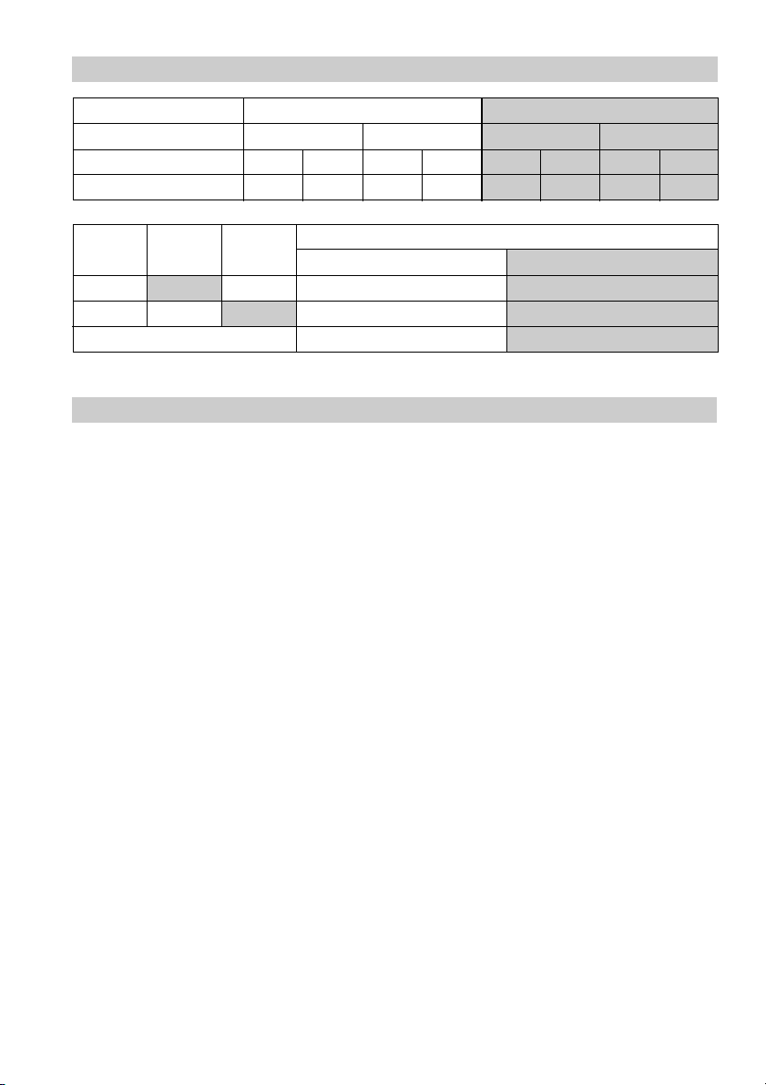
Ratings pursuant to article 9 of PED1) 97/23/EC
Type UBK 46
Fluid Gas, steam Liquid
Fluid group 1 2 1 2
Use no yes no yes
Type PN Class
UBK 46 Cl 300 15, 20, 25
UBK 46 PN 40 15, 20, 25
CE marking no
1
) PED = Pressure Equipment Directive
Exception pursuant to article 3.3
ATEX Directive 94/9/EC, 1999/92/EC
The equipment can be used in potentially explosive areas 0, 1, 2, 20, 21 and 22.
The equipment does not have its own potential source of ignition and is therefore not subject
to 94/9/EC.
The equipment does not require an Ex marking.
Nominal size DN
5
Page 6

Explanatory Notes
Scope of Supply
UBK 46
1 Thermostatic steam trap UBK 46
1 Installation manual
Spare parts
1 Kit as specified in the spare parts list on page 18
System description
The UBK 46 is a steam trap with adjustable condensate discharge temperature, thereby suppressing
the formation of flash steam.
Main field of application: Steam heated tracing systems.
Design: With corrosion-resistant Duo stainless steel (bimetallic) regulator unaffected by waterhammer
and Y-type large-surface strainer.
Installation in any position. When installed in horizontal lines cover must be on top.
Function
During start-up of the plant the Duo stainless steel plates are flat. The service pressure acts in the
opening direction, the valve is completely open. With rising condensate temperature the plates deflect
and draw the stage nozzle towards the closed position.
As the condensate temperature falls the deflection of the Duo stainless steel plates decreases and the
steam trap opens at the adjusted opening temperature.
Thermostatic and spring characteristics of the stack of stainless steel plates are balanced so that the
condensate is discharged without any flashing and at a constant temperature.
6
Page 7

Technical Data
04NP)*sgnitaRerutarepmeT/erusserP
seiresT-p 0E3puorglairetam,51elbat,1-2901NEot
lairetaM 501AMTSA/])8.22Cnoitangiseddlo(0640.1[HG052P
)ND(eziS52,02,51
noitcennoC 003ssalCEMSAsegnalF,04NPsegnalF
erusserpecivreS]rab[AMP0.042.038.520.421.32
erutarepmeT]C°[AMT05otpu01–002003053004
051ssalC)*sgnitaRerutarepmeT/erusserP
seiresT-p 1.1puorglairetam,43.61BEMSAot
lairetaM 501AMTSA/])8.22Cnoitangiseddlo(0640.1[HG052P
)ND(eziS52,02,51
noitcennoC051ssalCEMSAsegnalF
erusserpecivreS]rab[AMP7.910.412.014.85.6
erutarepmeT]C°[AMT02002003053004
*) When used for its intended purpose.
Admissible differential pressure1)2)
Differential pressure PMX [bar] 32
1
) Observe pressure/temperature ratings!
2
) Inlet pressure minus outlet pressure
Materials EN DIN ASTM
Body P250GH (1.0460) C22.8 (1.0460) A105
Cover P250GH (1.0460) C22.8 (1.0460) A105
Screws 42CrMo4 (1.7225) 42CrMo4 (1.7225) A193 B7
Cover gasket Graphite
Regulator Stainless steel
Other internals Stainless steel
7
Page 8

Technical Data – continued –
Corrosion Resistance
If the steam trap is used for the intended purpose, its safety is not impaired by corrosion.
Sizing
The trap body must not be subjected to pulsating loads. Welds and flanges of the trap are designed
to withstand dynamic loading (bending and alternative stress).
The dimensional allowances for corrosion reflect the latest state of technology.
Name Plate/Marking
According to EN 19 the name plate and the valve body indicate the type and design:
■ Type designation: UBK 46
■ Marking according to ATEX: not required
■ Stamp on valve body, e.g. specifies the quarter and the year of production
(Example: 4
th
quarter 2004).
Nominal size
4
04
Specification
8
Page 9

Technical Data – continued –
Capacity Chart UBK 46
1
2
Fig. 1
Hot water capacity at 10 K
1
below opening temperature
Cold water capacity at 20 °C
2
9
Page 10

Technical Data – continued –
Opening temperatures UBK 46
10
Fig. 2
Page 11

Design UBK 46
A
B
K
C
D
E
F
D
G
H
I
J
Fig. 3
11
Page 12

Key
Hexagon-head screw M10 x 25, ISO 4017, made of 24CrMo5 (1.7258)
A
Name plate
B
Cover
C
Regulator
D
Bush (interference fitted, not a spare part)
E
Cover gasket 40 x 48 x 2
F
Body
G
Strainer
H
Plug gasket A 24 x 29
I
Sealing plug
J
Setscrew for discharge temperature
K
12
Page 13

Installation
UBK46
The UBK 46 can be installed in any position. When installed horizontally the cover must be on top.
Design with flanged ends
1. Observe position of installation.
2. Observe flow direction. The flow direction arrow is located on the trap body.
3. Leave at least 70 mm free space around the equipment for subsequent disassembly of the cover C.
4. Remove plastic plugs. They are only used for transit protection.
5. Clean gasket surfaces of the two flanges.
6. Install steam trap.
Design with screwed sockets
1. Observe position of installation.
2. Observe flow direction. The flow direction arrow is located on the trap body.
3. Leave at least 70 mm free space around the equipment for subsequent disassembly of the cover C.
4. Remove plastic plugs. They are only used for transit protection.
5. Clean internal threads.
6. Install steam trap.
Design with socket-weld ends
1. Observe position of installation.
2. Observe flow direction. The flow direction arrow is located on the trap body.
3. Leave at least 70 mm free space around the equipment for subsequent disassembly of the cover
4. Remove plastic plugs. They are only used for transit protection.
5. Remove regulator as described under “Maintenance”.
6. Clean socket-weld ends.
7. Arc-weld trap only manually (welding process 111 and 141 complying to ISO 4063 or equivalent
standard).
Design with butt-weld ends
1. Observe position of installation.
2. Observe flow direction. The flow direction arrow is located on the trap body.
3. Leave at least 70 mm free space around the equipment for subsequent disassembly of the cover
4. Remove plastic plugs. They are only used for transit protection.
5. Clean butt-weld ends.
6. Arc-weld trap manually (welding process 111 and 141 complying to ISO 4063 or equivalent
standard) or use gas-welding process 3 in accordance with ISO 4063.
CC
C.
CC
CC
C.
CC
13
Page 14

Installation – continued –
Attention
■
Only qualified welders certified e. g. according to DIN EN 287 may weld the
steam trap into pressurized lines.
■
Do not insulate trap.
Heat treatment of welds
A subsequent heat treatment of the welds is not required.
Commissioning
UBK 46
The flanged connections of the UBK 46 must be permanently bolted, ensuring tight shut-off. If
necessary raise or lower the condensate discharge temperature. For more information refer to section
“Adjust discharge temperature” on the following page.
14
Page 15

Operation
Adjust discharge temperature
The steam trap opens within its rated pressure/temperature range at the opening temperature set at
our works. The opening temperature adjusted at our factory can be increased or decreased by max.
40 K. Fig. 2, Fig. 4
1. Observe danger note on page 4.
2. Unscrew body screws A and remove cover C from body G. Fig. 2
3. Wait until regulator D has cooled down to ambient temperature.
4. To increase the discharge temperature turn setscrew K of the regulator max. one turn to the left.
1
/8 of a turn corresponds to 5 K. Fig. 3
5. To decrease the discharge temperature turn setscrew K of the regulator max. one turn to the
6. Replace gasket F when damaged. If the cover C is new or taken from another trap the gasket F
7. Assemble cover and body. Tighten screws alternately to a torque of 25 Nm in several steps.
Tools
■
■
1
right.
/8 of a turn corresponds to 5 K. Fig. 3
has to be replaced.
Spanner 16 mm A.F. to DIN 3113, form B
Screwdriver size 3.5 to DIN 5265
15
Page 16

Operation – continued –
Adjust discharge temperature
12
Fig. 4
To decrease discharge temperature:
1
Max. 1 turn to the
1
§§
/8 turn
§ 5 K.
§§
To
increase discharge temperature:
2
Max. 1 turn to the
1
§§
/8 turn
§ 5 K.
§§
Service pressure [bar] 1 2 4 8 12 16 20 26 32
Factory set opening
temperature [°C]
16
right,
left,
60 64 72 84 93 102 110 118 128
Page 17

Maintenance
The UBK 46 does not require any special maintenance. However, if used in new installations which have
not been rinsed it may be necessary to check and clean the trap.
Danger
Risk of severe scalds and burns to the whole body!
Before carrying out maintenance work or loosening flanged connections or sealing plugs,
make sure that all connected lines are depressurised (0 bar) and cooled down to room
temperature (20 °C).
Check steam trap
You can check the trap for steam loss with GESTRA’s ultrasonic measuring unit VAPOPHONE
the test unit TRAPTEST
®
. The contact points required for this functional check are on the name plate
of the cover.
In case of steam loss clean the trap or replace the regulator.
Clean/ replace regulator
1. Observe danger note on page 4.
2. Unscrew body screws A and remove cover C from body G.
3. Unscrew, clean and check regulator D. Do not disassemble the regulator.
4. Replace regulator D in case of visible signs of damage or wear.
5. Clean body and internals. Clean all gasket surfaces.
6. Apply heat-resistant lubricant to all threads and sealing surfaces of the regulator and cover (use for
instance WINIX
®
2150).
7. Screw in regulator and tighten with a torque of 90 Nm.
8. Replace gasket F when damaged. Use the same cover C. If the cover C is new or taken from
another trap the gasket F has to be replaced.
9. Put cover onto the body. Tighten body screws A alternately to a torque of 25 Nm in several steps.
®
or
Clean / replace strainer
1. Observe danger note on page 4.
2. Loosen sealing plug J and unscrew together with strainer H.
3. Clean strainer, sealing plug and gasket surfaces.
4. Replace strainer und sealing plug in case of visible signs of wear or damage.
5. Replace gasket H if damaged.
6. Apply heat-resistant lubricant to the thread of the sealing plug (e. g. WINIX
®
2150).
7. Mount sealing plug J with gasket I and strainer H. Tighten sealing plug with a torque of
120 Nm.
WINIX® is a registered trademark of WINIX GmbH, Norderstedt
17
Page 18

Maintenance – continued –
Tools
■ Spanner 16 mm A. F. to DIN 3113, form B
■ Spanner 22 mm A. F. to DIN 3113, form B
■ Spanner 30 mm A. F. to DIN 3113, form B
■ Torque spanner 20 – 120 Nm to ISO 6789
Torques
Item Designation Torque [Nm]
D
A
J
All torques indicated refer to a room temperature of 20 °C.
Regulator 90
Body screws 25
Sealing plug 120
Spare Parts
Spare Parts List
Item Designation Ref. No.
DF
F
HIJ
I
*) Minimum order quantity 50 items. Contact your local dealer for smaller quantities.
Regulator with cover gasket 375 324
Cover gasket*)
40 x 48 x 2, graphite
Strainer with sealing plug and gasket 375 113
Strainer gasket*)
A 24 x 29, stainless steel
375 159
375 162
18
Page 19

Decommissioning
Danger
Risk of severe scalds and burns to the whole body!
Before carrying out maintenance work or loosening flanged connections or sealing plugs,
make sure that all connected lines are depressurised (0 bar) and cooled down to room
temperature (20 °C).
Disposal
Dismantle the equipment and separate the waste materials, using the material specification table
on page 7.
For the disposal of the equipment observe the pertinent legal regulations concerning waste disposal.
19
Page 20

Agencies all over the world
www.gestra.de
GESTRA
España
GESTRA ESPAÑOLA S.A.
Luis Cabrera, 86-88
E-28002 Madrid
Tel. 00 3491/51 52 032
Fax 003491 / 41 36 747; 51 52 036
E-mail: aromero@flowserve.com
Great Britain
Flowserve Flow Control (UK) Ltd.
Burrel Road, Haywards Heath
West Sussex RH 16 1TL
Tel. 00 44 14 44 / 31 44 00
Fax 00 44 14 44 / 31 45 57
E-mail: gestraukinfo@flowserve.com
Italia
Flowserve S.p.A.
Flow Control Division
Via Prealpi, 30
l-20032 Cormano (MI)
Tel. 00 39 02 / 66 32 51
Fax 003902 / 66 32 55 60
E-mail: infoitaly@flowserve.com
Polska
GESTRA POLONIA Spolka z.o.o.
Ul. Schuberta 104
PL - 80-172 Gdansk
Tel. 00 48 58 /306 10 -02 od 10
Fax 00 48 58 /306 33 00
E-mail: gestra@gestra.pl
Portugal
Flowserve Portuguesa, Lda.
Av. Dr. Antunes Guimarães, 1159
Porto 4100-082
Tel. 0035122/6 19 8770
Fax 0035122/6107575
E-mail: jtavares@flowserve.com
USA
Flowserve DALCO Steam Products
2601 Grassland Drive
Louisville, KY 40299
Tel.: 00 15 02 / 4 95 01 54, 4 95 17 88
Fax: 00 15 02 / 4 95 16 08
E-Mail: dgoodwin@flowserve.com
GESTRA AG
P. O. Box 10 54 60, D-28054 Bremen
Münchener Str. 77, D-28215 Bremen
Telephone +49 (0) 421 35 03 - 0
Fax +49 (0) 421 35 03- 393
E-Mail gestra.ag@flowserve.com
Internet www.gestra.de
810475-01/604cm · © 1998 GESTRA AG · Bremen · Printed in Germany
20
 Loading...