

Page 1

McCANNA Actuation Systems
17710-B
Ramcon Series 8/25 C/CR, 50/100 B/BR, 250/500 B/BR
Electric Actuators
Installation, Operation and Maintenance Instructions
Contents
Storage . . . . . . . . . . . . . . . . . . . . . . . . . . . . . . . . . . . . . . . . . . . . . . . . . . . . . . . . . . . . . . . . . . . . . . . . . . . . . . . . . . . . . . . . . . . . . . . . . . . . . . . . . . . 2
Installation . . . . . . . . . . . . . . . . . . . . . . . . . . . . . . . . . . . . . . . . . . . . . . . . . . . . . . . . . . . . . . . . . . . . . . . . . . . . . . . . . . . . . . . . . . . . . . . . . . . . . . . . . 2
Electrical . . . . . . . . . . . . . . . . . . . . . . . . . . . . . . . . . . . . . . . . . . . . . . . . . . . . . . . . . . . . . . . . . . . . . . . . . . . . . . . . . . . . . . . . . . . . . . . . . . . . . . . . . . 2
Mechanical . . . . . . . . . . . . . . . . . . . . . . . . . . . . . . . . . . . . . . . . . . . . . . . . . . . . . . . . . . . . . . . . . . . . . . . . . . . . . . . . . . . . . . . . . . . . . . . . . . . . . . . . . 2
Maintenance . . . . . . . . . . . . . . . . . . . . . . . . . . . . . . . . . . . . . . . . . . . . . . . . . . . . . . . . . . . . . . . . . . . . . . . . . . . . . . . . . . . . . . . . . . . . . . . . . . . . . . . 2
Inspection . . . . . . . . . . . . . . . . . . . . . . . . . . . . . . . . . . . . . . . . . . . . . . . . . . . . . . . . . . . . . . . . . . . . . . . . . . . . . . . . . . . . . . . . . . . . . . . . . . . . . . 6
Spare Parts . . . . . . . . . . . . . . . . . . . . . . . . . . . . . . . . . . . . . . . . . . . . . . . . . . . . . . . . . . . . . . . . . . . . . . . . . . . . . . . . . . . . . . . . . . . . . . . . . . . . . 6
Repairs – Warranty Terms and Conditions . . . . . . . . . . . . . . . . . . . . . . . . . . . . . . . . . . . . . . . . . . . . . . . . . . . . . . . . . . . . . . . . . . . . . . . . . . . . . 6
Adjustments . . . . . . . . . . . . . . . . . . . . . . . . . . . . . . . . . . . . . . . . . . . . . . . . . . . . . . . . . . . . . . . . . . . . . . . . . . . . . . . . . . . . . . . . . . . . . . . . . . . . . . . . 6
Troubleshooting . . . . . . . . . . . . . . . . . . . . . . . . . . . . . . . . . . . . . . . . . . . . . . . . . . . . . . . . . . . . . . . . . . . . . . . . . . . . . . . . . . . . . . . . . . . . . . . . . . . . . 7
Illustrations
Wiring Schematic . . . . . . . . . . . . . . . . . . . . . . . . . . . . . . . . . . . . . . . . . . . . . . . . . . . . . . . . . . . . . . . . . . . . . . . . . . . . . . . . . . . . . . . . . . . . . . . . . . . 3
8C-25C Unidirectional . . . . . . . . . . . . . . . . . . . . . . . . . . . . . . . . . . . . . . . . . . . . . . . . . . . . . . . . . . . . . . . . . . . . . . . . . . . . . . . . . . . . . . . . . . . . . . . . 4
8CR-25CR Reversible . . . . . . . . . . . . . . . . . . . . . . . . . . . . . . . . . . . . . . . . . . . . . . . . . . . . . . . . . . . . . . . . . . . . . . . . . . . . . . . . . . . . . . . . . . . . . . . . 4
50BR-100BR Reversible . . . . . . . . . . . . . . . . . . . . . . . . . . . . . . . . . . . . . . . . . . . . . . . . . . . . . . . . . . . . . . . . . . . . . . . . . . . . . . . . . . . . . . . . . . . . . . 5
250BR-500BR Reversible . . . . . . . . . . . . . . . . . . . . . . . . . . . . . . . . . . . . . . . . . . . . . . . . . . . . . . . . . . . . . . . . . . . . . . . . . . . . . . . . . . . . . . . . . . . . . 5
Page 2

2 17710-B
Flow Control Division
McCANNA Actuation Systems
Storage
If the actuator is not to be installed as soon as received, heated
indoor electrical instrument storage conditions must be provided. The
actuator and any auxiliary equipment should be protected from
corrosive materials and atmosphere, flooding, and dirty conditions.
Conduit openings should be plugged and must not be subjected to
rain, snow or water hosing. Storage must be in a place where other
materials will not be placed or dropped on the actuator.
Installation
Installation of this actuator in applications where life-threatening
conditions can be expected must include adequate
monitoring/warning, interlock, and/or redundant control equipment.
Electrical
A. The wiring and conduits must be installed in accordance with all
local codes and consistent with good practice for electrical work.
B. In hazardous areas the conduit seals required must be locally
installed. No conduit seal is provided in the actuator.
C. If the actuator case is used as a splice box, the cover must be
kept in place except when actually wiring or making adjustments.
When replacing the cover all wires must be clear of pinch and
scrape points and, if gasketed, proper gasket positioning must be
observed.
D. Each actuator must have its own control switch. Do not operate in
parallel with another actuator or other equipment.
E. Required and optional electrical connections are shown on the
wiring schematic(s) supplied with the actuator (located either on
the motor O.D. close to terminal block or inside of the housing)
and also shown on page 3.
CAUTION: The typical wiring schematics shown may not show
all wiring for actuators with optional features and must not be
used as the basis for final wiring.
Single-phase AC actuator: (Verify that the nameplate voltage is the
same as the AC supply voltage.) Connect actuator leads to the AC line
as shown on the wiring schematic.
DC actuator: (Verify that the supply voltage matches the nameplate
voltage.) The actuator rotation depends upon polarity at the terminals
and it is essential that the polarity of connections be as shown on the
wiring schematic supplied with the actuator.
Mechanical
A. The valve or other load to be driven must be free of obstructions
and must turn freely throughout its entire operating range.
B. If mechanical stops are a part of the equipment, adjustment of
these stops is necessary to avoid contact during normal
operation. Limit switch must stop motor before mechanical stops
are contacted.
C. If the actuator is to be field-mounted be sure that it is positioned
so that the operating range is compatible with the load; i.e., if load
is at its extreme clockwise position the actuator output shaft must
also be at the same clockwise limit.
D. When positioning the actuator for a direct in-line connection to a
valve, the two shaft centerlines must coincide to assure proper
operation and to avoid excessive side loading of either shaft. A
coupling with cross slots will provide some compensation for
small misalignment. Position so that there is not axial loading of
either shaft at any point of travel.
E. If connection is other than direct coupling, the linkages used must
operate freely and must be clear of all obstructions throughout
the complete travel range.
F. Unless specifically required to make other adjustments, the
actuator shaft travel for standard units will be clockwise when
viewed from the motor and cam side, or counter-clockwise when
viewed from the mounting flange side of the actuator with the
yellow and red circuit energized. The same is true for DC
actuators with polarity connection as shown on the wiring
schematic. Reversible actuators (standard configurations) will
rotate counter-clockwise, motor and cam end, when the yellow
and black leads are energized.
G. If adjustments are required, cam settings can be changed. (See
figures 1, 2, 3, and 4)
Maintenance
Maintenance recommendations given are for the typical or average
installation conditions. In severe installation conditions including
items such as corrosives, extremes of heat and cold, humidity, etc.,
and where the potential for dangerous or life-threatening conditions in
case of malfunction exist, more frequent and thorough maintenance
procedures will be required. Local conditions and procedures must be
used to determine an appropriate inspection and/or maintenance
program.
The McCANNA Ramcon electric actuator is completely enclosed by a
rugged housing designed to resist the most frequently encountered
installation atmospheres, and contains a closed, grease-filled gear
train. All standard AC motors are brushless induction types with no
commutators or brushes to wear or get dirty. For many installations
no formal or only minimum maintenance procedures will be required.
Page 3

17710-B 3
Flow Control Division
McCANNA Actuation Systems
NOTE: Series 23 includes models 8C, 8CR, 25C and 25CR. Series 14
includes models 50B, 50BR, 100B and 100BR. Series 16 includes
models 250BR and 500BR
Page 4
4 17710-B
Flow Control Division
McCANNA Actuation Systems
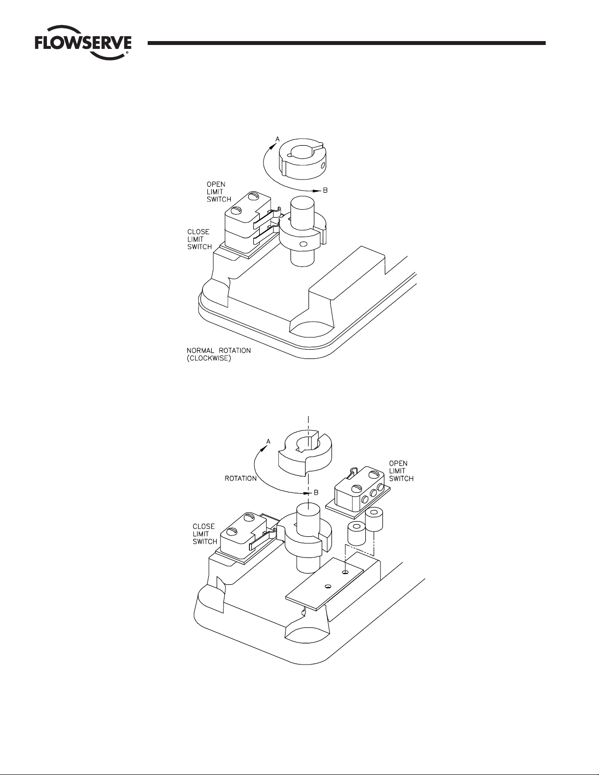
Figure 1: 8C-25C Unidirectional
Figure 2: 8C-25CR Reversible
Page 5
17710-B 5
Flow Control Division
McCANNA Actuation Systems
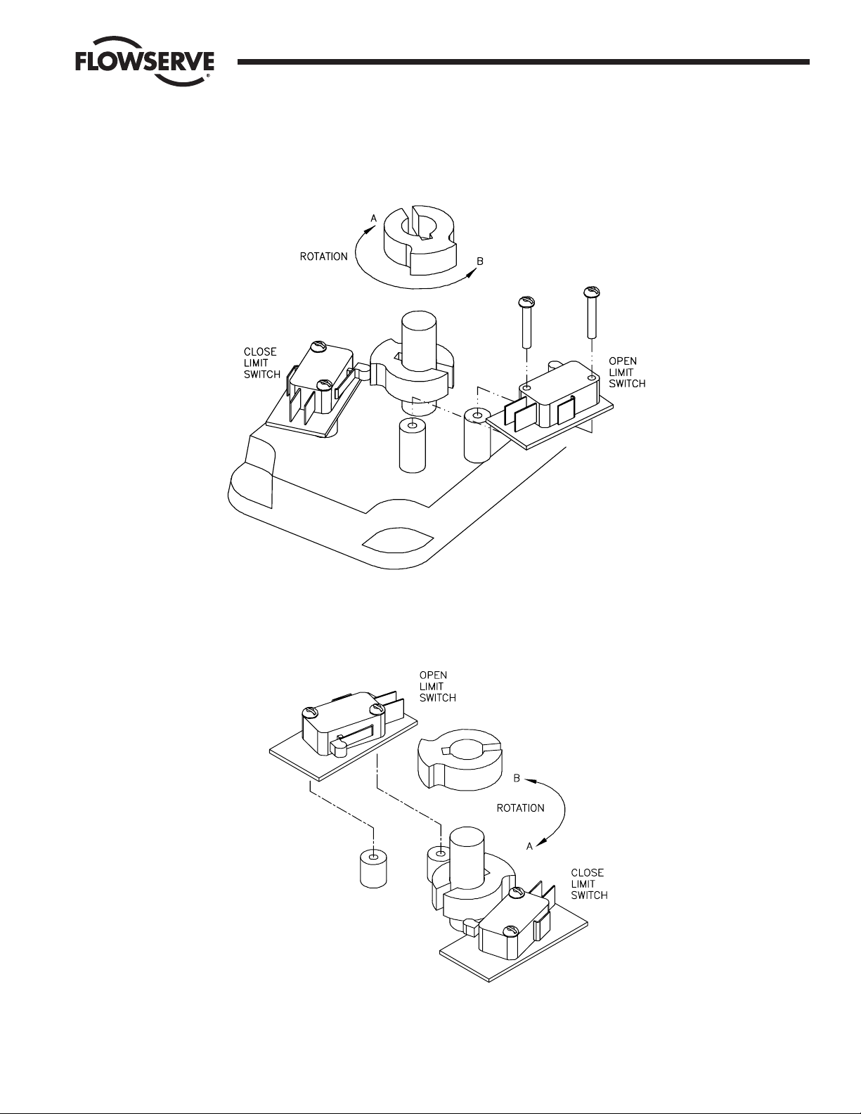
Figure 3: 50BR-100BR Reversible
Figure 4: 250BR-500BR Reversible
Page 6

6 17710-B
Flow Control Division
McCANNA Actuation Systems
A. Inspection
Inspect the actuator regularly to check:
• Any evidence of corrosion
•To make sure alignment is maintained relative to the load.
• That the actuator case has not been physically damaged.
• For excessive dirt and water entering actuator cases. (Clean
and correct as necessary).
• For evidence of loosening or shifting of parts due to vibration,
shock, wear or other conditions.
•Free action of brake and proper electrical release and holding
with no power.
• Any evidence of overheating.
• Any cracking or damage to wire joint and/or insulation.
• Any evidence of arcing or electrical shorts.
Under normal conditions, this inspection may be at intervals of
six months to a year. Where conditions are more severe, the
inspection should be at more frequent intervals as dictated by the
actual conditions. In all cases the consequences of a failure
should be a factor determining frequency of inspection or
servicing.
Always promptly check actuator in any case of malfunction or
erratic operation, and correct the cause.
B. Spare Parts
There has been no history of failure or weakness in any category
of parts which would dictate stocking of spares. Some users have
stocked items such as motors, capacitors, switches, gear trains,
complete actuators, or their combinations of parts and assemblies
depending upon their local conditions and requirements of
uninterrupted service.
When spare parts are required, include actuator model, and
description of part(s).
C. Repairs – Warranty Terms and Conditions
Before attempting repairs, modifications or addition of equipment
to the actuator by non-authorized personnel, the following
warranty terms and conditions should be reviewed.
Flowserve warrants its products against defects in materials and
workmanship for a period of one year from date of shipment from
its factory provided the equipment is properly installed and
operated. Liability is limited to repair, return of purchase price, or
replacement of any parts shown to be defective, and does not
extend to damage caused by accident, misuse, abuse, neglect,
tampering, or deterioration by corrosion. Products or parts not
manufactured by Flowserve are warranted only for the extent of
the original manufacturer’s warranty. There are no implied
warranties of fitness for a particular purpose. In no event shall
Flowserve be liable for loss of profits, loss by plant shutdown,
increased expense of operation, or other special or consequential
damages.
Should repair be necessary due to damage, wear, or malfunction,
identify any parts which may be required and contact your
McCANNA Ramcon Distributor or the factory. If it is necessary to
disassemble the actuator, observe proper orientation of all parts
and proper routing of all wires. Contact the factory for major
repair and RMA (Return Material Authorization) number.
Adjustments
NOTE: See Figures 1-4.
Unidirectional
TO ADJUST OPEN
1. Loosen set screw on second level cam
2. Rotate cam in direction “A” to reduce overtravel, “B” to reduce
undertravel
3. Tighten set screw
4. Run actuator to verify proper settings
TO ADJUST CLOSE
1. Loosen set screw on bottom cam
2. Rotate cam in direction “A” to reduce overtravel, “B” to reduce
undertravel
3. Tighten set screw.
4. Run actuator to verify proper settings
Reversible
TO ADJUST OPEN
1. Loosen set screw on second level cam
2. Rotate cam in direction “A” to reduce undertravel, “B” to reduce
overtravel
3. Tighten set screw
4. Run actuator to verify proper settings
TO ADJUST CLOSE
1. Loosen set screw on bottom cam
2. Rotate cam in direction “A” to reduce overtravel, “B” to reduce
undertravel
3. Tighten set screw.
4. Run actuator to verify proper settings
Page 7

17710-B 7
Flow Control Division
McCANNA Actuation Systems
Troubleshooting
Power interruption due to power
failure or from loose or broken
wires, tripped circuit breakers, etc.
High voltage causing burnout.
Shorted switches or other electric
components due to foreign material
or wiring not properly routed.
Correct position of declutch lever
(250BR, 500BR).
Damaged or corroded switch
contacts.
Low Voltage.
Capacitor function.
Gear Train free.
Motor alignment.
Brake not releasing.
Stops operating
Cam may be loose on the shaft.
Cam may be worn and miss the limit
switch.
Switch mounting may be loose.
Switch may be stuck on its closed
position.
Cam shaft may be bent away from
the switch.
Continuous turning
in one direction on
reversible actuator
Continuous turning
during one of the
travel segments on
unidirectional actuator
Reduced torque output
Hot areas, either line or ambient.
Excessive duty cycle.
Stalling due to incorrect cam setting.
(See Paragraph B under Mechanical
on page 2).
Obstruction preventing cam travel to
switching point.
Forward and reverse windings
powered at the same time.
Overheating
Power not getting to the motor.
Limit switch open.
Switch contact resistance.
Capacitor function on AC actuators.
Brush/commutator continuity on DC
actuators.
Optional brake not being released (not
wired, coil problems or relay
problems).
Actuator will not run
Brake not releasing.
Excessive torque in valve.
Both limit switches being powered
(control circuit or wiring).
Both motor windings being powered
(within actuator).
Actuator runs slower
than rating
Gear train may be worn, broken, or
incorrectly assembled in the field.
Correct position of declutch lever
(250BR, 500BR)
Motor turning but
output shaft stationary
Problem
Check for ...
Problem
Check for ...
NOTICE
McCANNA actuators are designed and manufactured using good workmanship and materials, and they meet all applicable industry standards.
Flowserve is anxious to avoid injuries and property damage which would result from misapplication of the product. Proper selection is
imperative. Examples of misapplication or misuse include use in a service in which the pressure/temperature rating is excessed or in a chemical
service incompatible with the materials of construction; use of undersized actuators; use of extremely fast actuation and/or continuous cycling on
standard product; making modifications of the product of any kind; failure to use caution on operating in high-temperature, high-pressure, or
highly hazardous services; failure to maintain product as recommended.
Page 8

Flow Control Division
McCANNA Actuation Systems
Flowserve Corporation has established industry leadership in the design and manufacture of its products. When properly selected, this Flowserve product is designed to perform its intended function
safely during its useful life. However, the purchaser or user of Flowserve products should be aware that Flowserve products might be used in numerous applications under a wide variety of industrial
service conditions. Although Flowserve can (and often does) provide general guidelines, it cannot provide specific data and warnings for all possible applications. The purchaser/user must therefore
assume the ultimate responsibility for the proper sizing and selection, installation, operation, and maintenance of Flowserve products. The purchaser/user should read and understand the Installation
Operation Maintenance (IOM) instructions included with the product, and train its employees and contractors in the safe use of Flowserve products in connection with the specific application.
While the information and specifications contained in this literature are believed to be accurate, they are supplied for informative purposes only and should not be considered certified or as a guarantee of
satisfactory results by reliance thereon. Nothing contained herein is to be construed as a warranty or guarantee, express or implied, regarding any matter with respect to this product. Because Flowserve
is continually improving and upgrading its product design, the specifications, dimensions and information contained herein are subject to change without notice. Should any question arise concerning
these provisions, the purchaser/user should contact Flowserve Corporation at any one of its worldwide operations or offices.
For more information about Flowserve Corporation, contact www.flowserve.com or call USA 1-800-225-6989.
FLOWSERVE CORPORATION
FLOW CONTROL DIVISION
McCANNA Actuation Systems
5114 Woodall Road,
P.O. Box 11318
Lynchburg, VA 24506-1318
Phone (434) 528-4400
Fax (434) 845-9736
© 2003 Flowserve Corporation, Irving, Texas, USA. Flowserve and McCANNA are registered trademarks of Flowserve Corporation. 17710-B 8/03 Printed in USA
 Loading...