

Page 1

NRS 2-5
Installation Instructions 810455-00
Level Switch Type NRS 2-5
1
Page 2
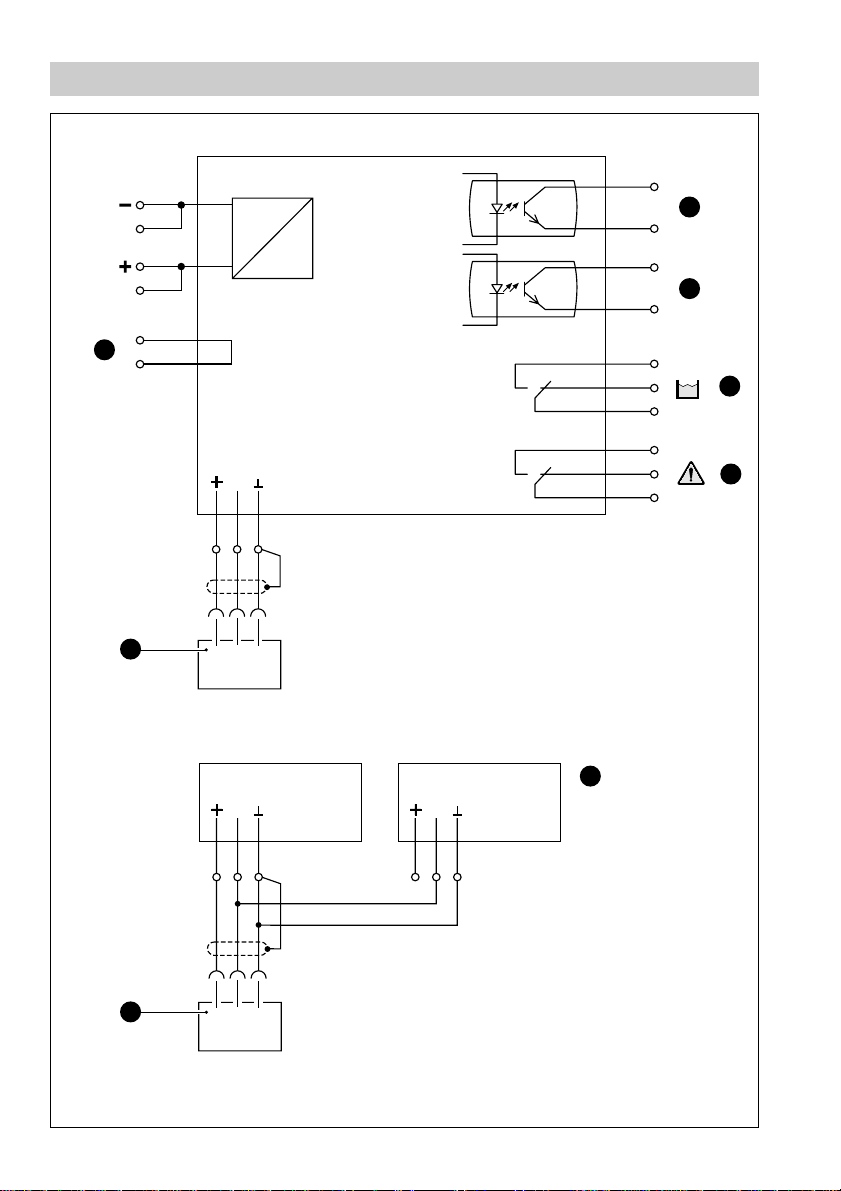
Wiring Diagram
24V DC
11
Fig. 1
C28
A28
A30
C30
A24
C24
10
DC
12V DC
M
C16
C18
1
NRG 211
DC
NRS 2-5
Illustrated relay position:
Alarm, malfunction
A18
32
A22
C22
A20
C20
C 8
A 10
C 12
A 2
C 4
A 6
5
6
MIN
7
8
2
Fig. 2
12V DC 12V DC
NRS 2-5 NRS 2-5
MM
C16
C18
A18
10
1
NRG 211
32
C16
C18
A18
9
Page 3

Dimensions
Fig. 3
A
B
NRS2-5
128.5
MIN
B
C
30.01
(6 TE)
3
Page 4

Parts Drawings
1
2
MAX 70°C
NRS2-5
%
MAX 95%
IP 10
3
4
Fig. 4
MIN
4
Page 5

Key
A
32 way screw-type connector
B
Fixing screw
C
19" Slide-in unit to DIN 41495
LED MALFUNCTION IN ELECTRODE
1
LED MALFUNCTION IN SUPPLY CABLE
2
3
LED LOW LEVEL ALARM
4
LED OPERATION
5
Switching contact ALARM (optocoupler)
6
Switching contact
7
Switching contact
8
Switching contact
9
Example of two low-level switches (redundancy)
10
Level electrode NRG 211
11
Test loop
MALFUNCTION (optocoupler)
ALARM (relay)
MALFUNCTION (relay)
5
Page 6

Contents
Page
Important Notes
Safety note ...................................................................................................................... 7
Warning ........................................................................................................................... 7
Explanatory Notes
Scope of supply ..............................................................................................................7
System description ......................................................................................................... 8
Function .......................................................................................................................... 8
Design ............................................................................................................................. 8
Technical Data ................................................................................................................9
Installation
NRS 2-5 c/d ....................................................................................................................9
Wiring
NRS 2-5 c/d ..................................................................................................................10
Commissioning
Check wiring .................................................................................................................11
Apply mains voltage...................................................................................................... 11
Functional test .............................................................................................................. 11
Table 1........................................................................................................................... 11
Annex
Warning .........................................................................................................................12
Fault finding list .............................................................................................................12
Declaration of conformity ..............................................................................................13
6
Page 7

Important Notes
Safety Note
Low level switches are essential safety devices that are required according to the
approvals for the equipment to which they are fitted.
Use low level switch NRS 2-5 only for indicating min. water level.
The equipment must only be installed by qualified staff.
Qualified staff are those persons who – through adequate training in electrical
engineering, the use and application of safety equipment in accordance with
regulations concerning electrical safety systems, and first aid & accident
prevention – have achieved a recognised level of competence appropriate
to the installation and commissioning of this critical safety device.
Warning
The terminal strip of the NRS 2-5 is live during operation. This presents
the danger of electric shock. Cut off power supply before mounting or
removing the case lid.
Explanatory Notes
Scope of supply
NRS 2-5c
1 Level switch, 19" slide-in unit, front panel to DIN 41494, part 5, 6 TE
(TE = division units; 1 TE = 5.08 mm)
2 Guide rails
1 Screw-type connector
1 Installation instructions
NRS 2-5d
1 Level switch, 19" slide-in unit, front panel to DIN 41494, par t 5, 6 TE
1 Installation instructions
7
Page 8

Explanatory Notes – continued –
System description
The level switch NRS 2-5 is an analogue electronic amplifier for the capacitance
electrode NRG 211.
In combination with this level electrode it can detect low water level. In addition, the
level switch evaluates possible malfunction signals coming from the electrode and
monitors the electrode supply cable.
The level switch in combination with the level electrode can be used as par t of a
low-water level limiting system in steam boilers (separate approval).
Function
The NRS 2-5 has one channel and is provided with a power supply unit and a
voltage decoder. The supply voltage (12VDC) going to the electrode is converted
into a measuring voltage as a function of the operating mode. The signal decoder
assigns the measuring voltage to an operating mode which is indicated by LEDs at
the front panel of the NRS 2-5.
The level switch is designed for four operating modes:
■
Normal operation
■
Low-level alarm
■
Malfunction in level electrode
■
Malfunction in connecting cable
In the case of a low-level alarm or malfunctions the corresponding output relay will
be de-energized. Optocouplers are connected in parallel and assigned to the
output relays as additional switching elements.
Design
NRS 2-5c:
19" Slide-in unit with guide rails and 32 pole screw-type connector for installation in
19" magazines to DIN 41494 part 5. Front panel to DIN 41494, part 5, 6 TE
NRS 2-5d:
Spare 19" slide-in unit, front panel to DIN 41494, part 5, 6 TE
8
Page 9

Technical Data
Input – measuring voltage
1–10 V DC (measuring voltage coming from level electrode)
Output – measuring voltage
12VDC (supply voltage going to level electrode)
Output
2 volt-free relay contacts
Max. contact rating with switching voltages of 24/115 /230V AC: 4 A resistive, 0.75A
inductive at cos ϕ 0.5.
Max. contact rating with switching voltage 24 V DC: 4A
Contact material: silver, hard-gold plated
2 optocouplers (npn), short-circuit protected due to inherent current limiting
characteristics, max. ratings: 70 V, 10 mA
Indicators and adjustors
1 green LED
ALARM, 2 LEDs MALFUNCTION, 1 LED OPERATION
Mains voltage
24 VDC
Power consumption
2VA
Case materials
NRS 2-5c
Front panel: aluminium, Fig. 7
NRS 2-5d
Front panel: aluminium, Fig. 7
Weight
NRS 2-5 c/d: approx. 0.6 kg
Installation
NRS 2-5c
1. Install plastic guide rails into 19" magazine.
2. Install screw-type connector.
3. Insert level switch into the 19" magazine and fasten with screws .
B
NRS 2-5d
1. Insert level switch into the 19" magazine and fasten with screws .
B
Tools
■
Screwdriver (5.5/100)
9
Page 10

Wiring
NRS 2-5
Use screened four-core cable, conductor size 0.8 mm², max. cable length 500 m for
the supply of the electrode.
Wire screw-type connector according to wiring diagram, Fig. 1
Wiring diagram
See wiring diagram page 2.
Attention
■
To protect the relay contacts fuse the control circuit with T 2.5A or
according to TRD regulations (1.0 A for 72 h operation).
■
The screen must not make any other electrical contact.
Important Note
■
Connect screen only to terminal A18 of the level switch.
■
The monitoring of the level electrode and the monitoring of the
connecting cable can be integrated in the safety circuit. For this
purpose connect the safety circuit to the relay output
■
The rated voltage is indicated on the name plate.
■
When switching off inductive loads, voltage spikes are produced that
may impair the operation of control and measuring systems.
Inductive loads should be provided with commercial arc
suppressor RC combinations, e. g. 0.1 µF/100Ω.
MALFUNCTION.
Tools
■
Screwdriver for slotted screws, size 2.5, completely insulated acc. to VDE 0680
10
Page 11
Commissioning
Check wiring
Check whether the NRS 2-5 and the associated system component NRG 211 are
wired according to the wiring diagram. Fig.1, Fig. 2
Apply mains voltage
Switch on mains supply. The green LED is illuminated. Fig. 4
4
Functional test
NRS 2-5 c/d
1. After switching on the mains voltage the green LED must be permanently
4
illuminated. Fig. 4
2. Lower the water level until it falls below the low-level mark.
The red LED at the level switch must light up.
3
3. Raise the water level until it exceeds the low-level mark. The red LED must
extinguish.
4. After removing the terminal box from the level electrode the yellow LED must
2
light up (malfunction in connecting wire).
5. Bridge terminals C16 and C18. The yellow LED must light up (malfunction in
1
electrode).
The measuring voltages of the different operating modes are represented in table 1.
Table 1
Measuring voltage U
≤1V
Decoded
M
Malfunction in electrode supply cable
(short circuit, interruption)
1V–4V Electrode exposed, low level
4V–7V Electrode submerged
≥ 9V
Malfunction in electrode (defective insulating seal,
leaking stuffing box)
11
Page 12

Annex
Warning
The terminal strip of the NRS 2-5 is live during operation. This presents the
danger of electric shock.
Cut off power supply before inserting or removing the 19" slide-in unit and
before undertaking any installation or maintenance work.
Fault finding list
Fault: The level switch raises an alarm during normal operation.
Remedy: Check whether the green LED is illuminated. If not, check whether the
4
mains voltage is applied.
Fault: The yellow LED is illuminated.
1
Remedy: The level electrode is defective. Replace the equipment.
Fault: The yellow LED is illuminated.
2
Remedy: Check whether the connecting line to the electrode is interrupted.
If faults occur that are not listed above, please contact our subsidiary or agency in
your country.
12
Page 13

Annex – continued –
Declaration of conformity
We hereby declare that the equipment NRS 2-5 c/d conforms to the following
European guidelines:
■
LV guideline 73/23/EWG version 93/68/EWG
■
EMC guideline 89/336/EWG version 93/68/EWG
which are based on the following harmonised standards:
■
LV standard EN 60947-5-1: 1991
■
EMC standard EN 50081-2, EN 50082-2
This declaration is no longer valid if modifications are made to the equipment without
consultation with us.
Bremen, 28th April 1997
GESTRA GmbH
Dr. Anno Krautwald
Dr. Christian Politt
13
Page 14

GESTRA Gesellschaften · GESTRA Companies · Sociétés GESTRA · Sociedades Gestra · Società GESTRA
GESTRA Gesellschaften · GESTRA Companies · Sociétés GESTRA · Sociedades Gestra · Società GESTRA
Vertretungen weltweit · Agencies all over the world · Représentations dans le monde entier · Representaciones en todo el mundo · Agenzie in tutto il mondo
Vertretungen weltweit · Agencies all over the world · Représentations dans le monde entier · Representaciones en todo el mundo · Agenzie in tutto il mondo
Italia
España
España
GESTRA ESPAÑOLA S.A.
GESTRA ESPAÑOLA S.A.
Luis Cabrera, 86-88
Luis Cabrera, 86-88
E-28002 Madrid
E-28002 Madrid
Tel. 003491/5152032
Tel. (091) 5 152 032
Fax 003491/413 6747 ; 51520 36
Fax (091) 4 136 747; (091) 5 152 036
E-mail: gestra@gestra.es
France
France Portugal
GESTRA S.A.R.L.
10 Avenue du Centaure, BP 8263
Flowserve Flow Control S.A.S.
F-95801 CERGY PONTOISE
10 Avenue du Centaure, BP 8263
Tél. (01) 34.43.26.60
F-95801 CERGY PONTOISE CEDEX
Fax (01) 34.43.26.87
Tél. 00331/34432660
Fax 00331/34432687
Great Britain
E-mail: gnation@flowserve.com
GESTRA (U.K.) LTD.
9-11 Bancroft Court
Italia
Hitchin, Hertfordshire, SG5 1PH
Tel. (0 14 62) 4316 81
Italgestra S.r.l.
Fax (0 14 62) 4203 96
Via Carducci 125
l-20099 Sesto San Giovanni (MI)
Tel. 003902/241012.1
Fax 003902/241012.460
E-mail: info@italgestra.it
Polska
GESTRA POLONIA Spolka zo.o.
ITALGESTRA S.r.l.
Ul. Schuberta 104, P.O. Box 71
Via Carducci 125
PL-80-172 Gdansk
l-20099 S.S. Giovanni (MI)
Tel. 004858/3061002 oder 3061010
Tel. (02) 2 6297-0
Fax 004858/3061003 oder 3063300
Fax (02) 26 2974 60
E-mail: gestra@gestra.pl
Polska
GESTRA POLONIA Spolka z o.o.
Ul. Schuberta 104
GESTRA PORTUGUESA VALVULAS LDA.
PL-80-172 Gdansk
Av. Dr. Antunes Guimarães, 1159
Tel. (058) 306 10 02
Porto 4100-082
Fax (058) 306 10 03
Tel. 0035122/ 6198770
Fax 0035122/6107575
Portugal
E-mail: gestra@gestra.pt
GESTRA PORTUGUESA VALVULAS LDA.
Av. Dr. Antunes Guimarães, 1159
P-4100 Porto
Tel. (02) 6 107551
Fax (02) 6 10 75 75
®
®
GESTRA GmbH
GESTRA GmbH
Postfach 10 54 60
Postfach 10 54 60
D-28054 Bremen
D-28054 Bremen
Hemmstraße 130
Münchener Str. 77
D-28215 Bremen
D-28215 Bremen
Tel. +49 (0) 421 35 03- 0
Tel. +49 (0) 421 35 03-0
Fax +49 (0) 421 35 03-393
Fax+49 (0) 421 3503-393
Internet www.gestra.de
E-mail
gestra.gmbh@gestra.de
E-mail
gestra.gmbh@gestra.de
Internet www.gestra.de
A Unit of Flowserve Corporation
An Invensys company
810455-00/999c · ©1999 GESTRA GmbH · Bremen · Printed in Germany
14
 Loading...