

Page 1

GESTRA
GESTRA Steam Systems
LRG 16-40
LRG 17-40
Installation Instructions 818524-01
Conductivity Electrode LRG 16-40
Conductivity Electrode LRG 17-40
1
Page 2

Contents
Page
Important Notes
Usage for the intended purpose ..............................................................................................................4
Safety note .............................................................................................................................................4
Danger ...................................................................................................................................................4
PED (Pressure Equipment Directive) ........................................................................................................4
ATEX (Atmosphère Explosible) .................................................................................................................4
Explanatory Notes
Scope of supply ...................................................................................................................................... 5
Description .............................................................................................................................................5
Function .............................................................................................................................................5, 6
System components ...............................................................................................................................6
Design .................................................................................................................................................... 6
Technical Data
LRG 16-40, LRG 17-40 .....................................................................................................................
Corrosion resistance ............................................................................................................................... 9
Sizing .....................................................................................................................................................9
Name plate / marking ...........................................................................................................................10
Dimensions LRG 16-40 ........................................................................................................................
Dimensions LRG 17-40 ........................................................................................................................
Key .......................................................................................................................................................14
Functional Elements
LRG 16-40 / LRG 17-40 ........................................................................................................................13
Key .......................................................................................................................................................14
Installation
Installation notes ..................................................................................................................................15
Mounting conductivity electrode ...........................................................................................................15
Terminal box .........................................................................................................................................16
Opening terminal box ............................................................................................................................16
Aligning terminal box ............................................................................................................................ 16
Removing terminal box .........................................................................................................................16
Mounting terminal box .......................................................................................................................... 17
Closing terminal box .............................................................................................................................17
Tools ....................................................................................................................................................17
Example of Installation
Conductivity metering ........................................................................................................................... 18
Conductivity metering and continuous boiler blowdown ..................................................................18, 19
Key .......................................................................................................................................................19
7 – 9
11
12
2
Page 3

Contents – continued –
Page
Wiring
Bus cable .............................................................................................................................................20
Note .....................................................................................................................................................20
Assigning the connector and jack .........................................................................................................20
Wiring diagram of conductivity electrode LRG 16-40, LRG 17-40 .................................................... 21, 22
Attention ...............................................................................................................................................22
Basic Settings
Factory settings .................................................................................................................................... 22
Commissioning
Check wiring ........................................................................................................................................23
Apply mains voltage..............................................................................................................................23
Setting parameters ...............................................................................................................................23
Operation
Start .....................................................................................................................................................23
System Malfunctions
Causes .................................................................................................................................................24
Note .....................................................................................................................................................24
Systematic malfunction analysis ........................................................................................................... 25
Malfunctions
Fault finding list for troubleshooting ................................................................................................ 26, 27
Cleaning measuring electrode .............................................................................................................. 27
Replacing electronic circuit board ......................................................................................................... 27
Note .....................................................................................................................................................27
Decommissioning
Replacing conductivity electrode ...........................................................................................................28
Danger / Attention ................................................................................................................................. 28
Disposal................................................................................................................................................28
Annex
CAN bus ...............................................................................................................................................29
Factory set node IDs .............................................................................................................................29
Node ID ................................................................................................................................................29
Establishing / changing node ID ............................................................................................................ 30
Attention ...............................................................................................................................................30
Table “Node ID” ....................................................................................................................................31
Declaration of conformity ......................................................................................................................32
3
Page 4
Important Notes
Usage for the intended purpose
Use conductivity electrodes LRG 16-40/LRG 17-40 only for measuring the electrical conductivity of
liquid fluids.
For conductivity limiting or continuous boiler blowdown the conductivity electrodes LRG 16-40/
LRG 17-40 must only be used in conjunction with TDS controller LRR 1-40 and an operating terminal &
display unit type URB or SPECTORcontrol.
To guarantee a trouble-free operation observe the requirements made on water quality as specified in
the pertinent TRD and EN regulations.
Safety note
The equipment must only be installed and commissioned by qualified staff.
Maintenance and service work must only be performed by adequately trained persons who have
a recognized level of competence.
Danger
When loosening the electrode steam or hot water might escape.
This presents the danger of severe scalding. It is therefore essential not to remove or
install the electrode unless the boiler pressure is verified to be zero.
The electrode is hot during operation. This presents the danger of severe burns to hands
and arms. Installation and maintenance work should only be carried out when the system
is cold.
PED (Pressure Equipment Directive)
The equipment fulfills the requirements of the Pressure Equipment Directive (PED) 97/23/EC.
Applicable in fluids of group 1 and 2. With CE marking (apart from equipment according to section 3.3).
ATEX (Atmosphère Explosible)
According to the European Directive 94/9/EC the equipment must not be used in explosion-risk areas.
4
Page 5

Explanatory Notes
Scope of supply
LRG 16-40
1 Level electrode type LRG 16-40
1 S. S. joint ring
1 Terminating resistor 120
1 Installation manual
LRG 17-40
1 Level electrode type LRG 17-40
1 S. S. joint ring
1 Terminating resistor 120
1 Installation manual
Description
The conductivity electrode LRG 1x-40 consists of a TDS (= Total Dissolved Solids) monitoring electrode
for conductivity measurement, a temperature sensor for detecting the fluid temperature and a conductivity transmitter that is fully integrated in the terminal box.
The equipment is of the two electrode type and works according to the conductometric measurement
principle, measuring the electrical conductivity of electrically conductive fluids.
Together with the TDS controller LRR 1-40 and an operating device type URB or SPECTOR
the conductivity electrode LRG 1x-40 can be used as conductivity limiter and continuous blowdown
controller in steam boilers and (pressurized) hot water plants.
The data exchange between the conductivity electrode LRG 1x-40, the control and operating equip
ment and other devices is effected by the CAN-Bus to ISO 11898, using the CANopen protocols.
∅ 33 x 39, form D, DIN 7603 (made of 1.4301), bright annealed
∅ 33 x 39, form D, DIN 7603 (made of 1.4301), bright annealed
Ω
Ω
control
-
Function
A measuring current of variable frequency flows through the fluid and creates a potential gradient
between the measuring electrode and the measuring tube. The potential gradient is evaluated as
measuring voltage UU.
The electrical conductivity is a function of temperature. To relate the measured values to a reference
temperature the resistance thermometer integrated in the electrode measures the fluid temperature.
The electrical conductivity is calculated from the measuring voltages UU and UI and – through
temperature compensation – is based on a reference temperature of 25 °C.
The electrical conductivity is a non-linear function of temperature. For the compensation of the
measured values one of the following three procedures can be applied:
n Temperature compensation Auto: The conductivity electrode records the specific conductivity/
temperature curve of the respective fluid and based on the data obtained, performs the compensation.
The auto-curve temperature compensation is suitable for boilers operating with variable pressure,
which means that the boiler does not have a fixed working pressure (e. g. low load 10 bar, full load
15 bar). The system detects in steps of 10°C all temperatures and conductivity values from 100 °C
to the service temperature. For this purpose the boiler must reach its working pressure (with variable
pressure operation: max. allowable working pressure). If the standard curve is not suitable for variable
pressure operation, use can be made of the recorded curve.
5
Page 6

Explanatory Notes – continued –
Function – continued –
n Temperature compensation NORM: The conductivity/temperature curves of 11 normally used
conditioning agents are stored in the electrode and can be selected.
The standard curve temperature compensation is suitable for boilers operating with variable pressure,
which means that the boiler does not have a fixed working pressure (e.g. low load 10 bar, full load
15 bar). The standard curves of feedwater conditioning agents with different basic conductivities com
pensate for the influence of the temperature on readings within the operating range.
n Temperature compensation LINEAR: A fixed temperature coefficient (Tk) is used to correct the
measured conductivity value linearly.
The gradient (default setting: 2.1 % / °C) is normally used for steam boilers operating with constant
pressure. The conductivity is ascertained at an ambient temperature of 25°C. The cell constant can
be modified in order to calibrate the value measured by the electrode. The gradient can be verified at
operating pressure with the aid of a calibrated conductivity meter.
At regular intervals the conductivity electrode LRG 1x-40 sends a data telegram via CAN-bus to the
controller with the following information:
n Measured conductivity value, referred to 25°C as actual value (X),
n Measuring range / adaptation of actual value output,
n Alarm: self-monitoring of electrode supply cables,
n Alarm: temperature sensor defective,
n Alarm: excessively high temperature in terminal box.
A short circuit in the cables leading to the measuring electrode, the measuring tube and the resistance
thermometer or the interruption of the data transmission via CAN bus will be indicated by a malfunction message.
A sensor monitors the temperature in the terminal box and indicates a malfunction if the limit value is
exceeded.
-
System components
LRR 1-40
Digital switching controller for conductivity electrode LRG 1x-40
Functions: Conductivity limiter, continuous blowdown controller
Data exchange via CAN bus to ISO 11898 using CANopen protocol
URB 1, URB 2
Operating & display unit
Functions: Parameterization, indication via LCD display
Data exchange via CAN bus to ISO 11898 using CANopen protocol
Design
LRG 1x-40
Screwed 1", ISO 228-1.
Fig. 3, Fig. 4
6
Page 7

Technical Data
LRG 16-40, LRG 17-40
Type approval no.
TÜV.WÜL.02-007
EG BAF-MUC 02 05 103881 003
Service pressure
LRG 16-40: 32 bar at 238°C
LRG 17-40: 60 bar at 275°C
Connection
Screwed 1" BSP (to ISO 228-1)
Materials
Screw-in enclosure: 1.4571, X6CrNiMoTi17-12-2
Measuring electrode/reference tube/screw: 1.4571, X6CrNiMoTi17-12-2
Electrode insulation: PTFE
Terminal box: 3.2161 G AlSi8Cu3
Spacer disc: LRG 16-40: PEEK
Spacer disc: LRG 17-40: PEEK HT
Length of installation / measuring length
200, 300, 400, 500, 600, 800 and 1000 mm
Temperature sensor
Resistance thermometer PT 1000
Cell constant C
-1
0.2 cm
Conductivity measuring range
0.5 – 12000 μS/cm at 25°C
0.25 – 6000 ppm (parts per million)
Note
The electrical conductivity is measured in μS/cm. For ppm (parts per million) use the
following conversion: 1 μS/cm = 0.5 ppm.
7
Page 8

Technical Data – continued –
LRG 16-40, LRG 17-40 – continued –
Measuring cycle
1 sec.
Accuracy
5 %, referred to conductivity readings without temperature compensation
Temperature compensation
Type of temp. compensation can be adjusted with URB or SPECTORcontrol:
n Temperature compensation AUTO:
with conductivity/temperature curve characteristic of the installation.
n Temperature compensation NORM:
with standard conductivity/temperature curve.
n Temperature compensation LINEAR:
with set temperature coefficient (Tk).
Time constant T (measured as specified in DIN 3440)
Temperature: 9 sec.
Conductivity: 14 sec.
Input/Output
CAN bus interface with power supply 18 – 36 V DC, short circuit protected
Data exchange
CAN-bus to ISO 11898, CANopen protocol
Power consumption
3.8 W
Fuse
Electronic thermal fuse Tmax 85°C, hysteresis -2K.
Indicators and adjustors
Two LEDs for internal status messages.
One 10-pole code switch for node-ID and baud rate settings.
Electric connection
M 12 sensor connector, 5 poles, A coded
M 12 sensor jack, 5 poles, A coded
Protection
IP 65 to EN 60529
Ambient temperature
Max. 70°C
Weight
Approx. 2.5 kg
8
Page 9
Technical Data – continued –
LRG 16-40, LRG 17-40 – continued –
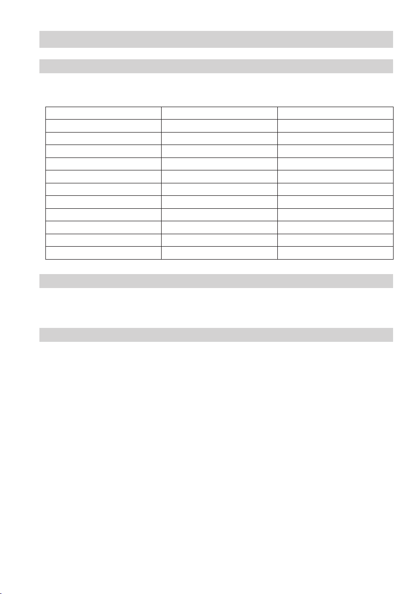
The standard conductivity-/temperature curves can be adjusted using the operating & display devices
SPECTORcontrol and URB.
Standard curve Conditioning agent Basic conductivity at 25°C
1 NaOH (caustic soda) 260 μS/cm
2 NaOH (caustic soda) 1080 μS/cm
3 NaOH (caustic soda) 5400 μS/cm
4 NaOH (caustic soda) 11000 μS/cm
5 Na3PO4 (trisodiumphosphate) 190 μS/cm
6 Na3PO4 (trisodiumphosphate) 1100 μS/cm
7 Na3PO4 (trisodiumphosphate) 5900 μS/cm
8 Na3PO4 (trisodiumphosphate) 11200 μS/cm
9 Na2SO3 (sodium sulfite) 980 μS/cm
10 Dipolique 444 200 μS/cm
11 Levoxin 195 μS/cm
Corrosion resistance
If the conductivity electrode LRG 1x-40 is used for its intended purpose, its safety is not impaired by
corrosion.
Sizing
The electrode body must not be subjected to sharp increases/decreases in pressure. The dimensional
allowances for corrosion reflect the latest state of technology.
9
Page 10
Technical Data – continued –
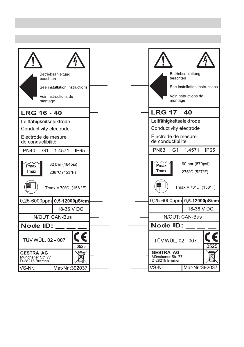
Name plate / Marking
Safety note
Equipment designation
Pressure rating, thread type,
material number, protection
Pressure/temperature rating
Fig. 1
10
Measuring range
Power rating
Output characteristics
Node ID
CE marking
Manufacturer / Disposal note
Spare part
specification
Fig. 2
Page 11
Technical Data – continued –
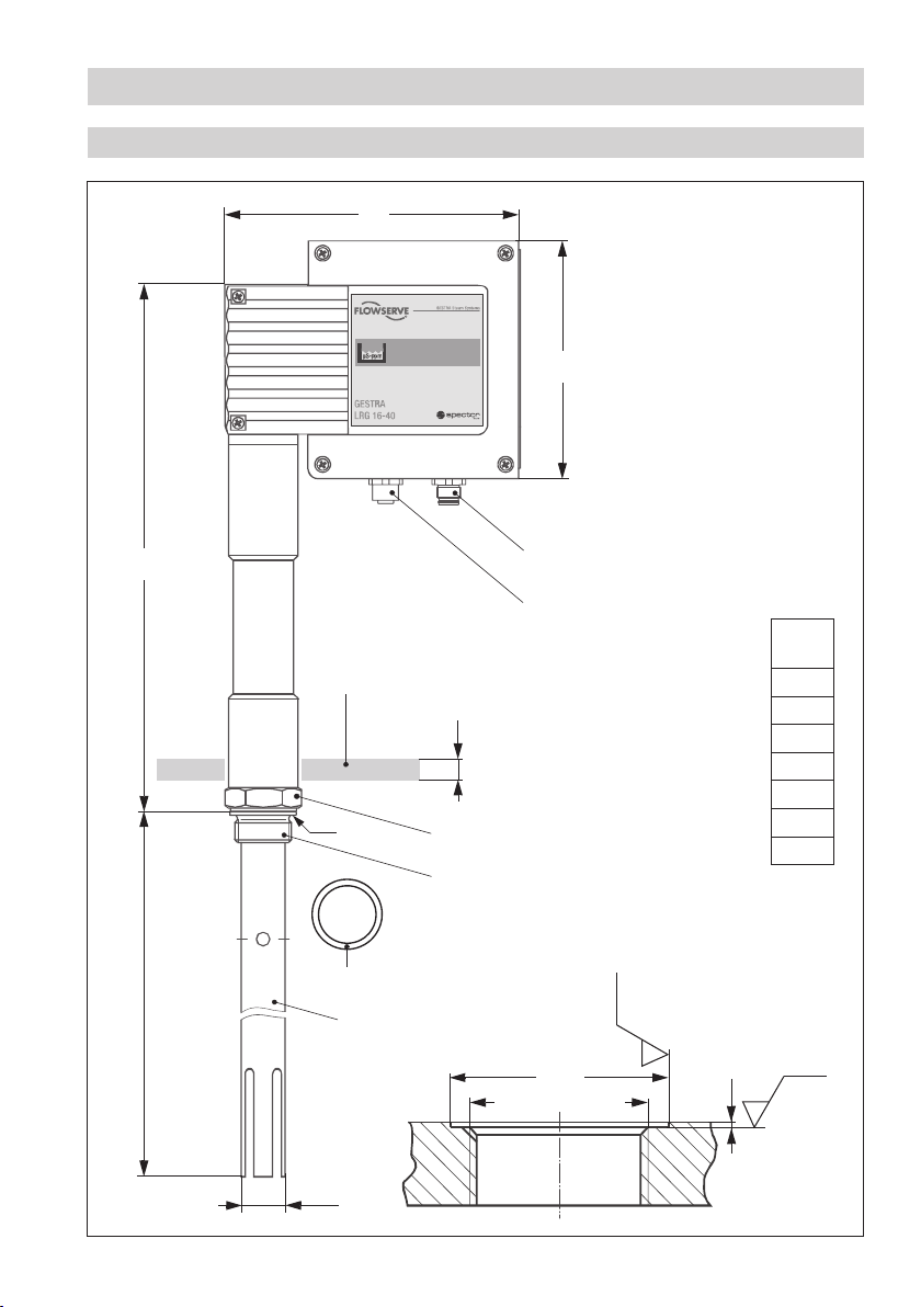
Dimensions LRG 16-40
173
140
b = 68
G
Fig. 3
336
∅ 28
C
D
E
F
A
B
20
A. F. 41
1" BSP (ISO 228-1)
∅ 40
1" BSP (ISO 228-1)
G
[mm]
200
300
400
500
600
800
1000
Ra 12.5
Ra 3.2
0.5
11
Page 12

Technical Data – continued –
Dimensions LRG 17-40
173
140
b = 68
G
Fig. 4
336
∅ 28
C
D
E
F
A
B
20
A. F. 41
1" BSP (ISO 228-1)
1" BSP (ISO 228-1)
∅ 40
G
[mm]
200
300
400
500
600
800
1000
Ra 12.5
Ra 3.2
0.5
12
Page 13

1
2
3
4
5
6
PT1000
Schaltwippe weiß
IP 65
MAX 70°C
MAX 95%
Functional Elements
LRG 16-40 / LRG 17-40
Fig. 5
Fig. 6
O
N
M
H
I
L
1
32
Code switch, white
J
K
13
Page 14

Technical Data / Functional Elements – continued –
Key
1 LED 1 (green)
2 LED 2 (red)
3 Code switch
A M 12 sensor connector, 5 poles, A coded
B M 12 sensor jack, 5 poles, A coded
C Thermal insulation
D Seating surface
E Joint ring ∅ 33 x 39, form D, DIN 7603, material: 1.4301, bright-annealed
F Measuring tube
G Length of installation and measuring length
H Cover screws (cross recess head screws M4)
I Cover
J Terminal strip
K Fixing screws for electronic circuit board
L Connection for functional earth
M Joint ring
N Fixing nut for terminal box
O Terminal lugs for electrode wires, functional earth
14
Page 15

Installation
Installation notes
Attention
n The seating surfaces and threads on the vessel and mounting flange must be
accurately machined.
n Use only the supplied ring joint ∅ 33 x 39, form D, to DIN 7603,
material: 1.4301, bright-annealed!
n Do not insulate the threads with hemp or PTFE tape!
n Do not lag the electrode body.
n Install electrode horizontally or with a vertical inclination. The measuring surface must
be permanently submerged.
n Provide a spacing of approx. 30 mm between the lower end of the measuring tube
and the boiler wall, the smoke tubes and any other metallic fittings as well as the low
water level.
n The specified torques must be strictly observed.
Note
n For the approval of the boiler standpipe the relevant local and national regulations must
be observed.
n Three examples of installation are shown on pages 18 and 19.
Mounting conductivity electrode
1. Check seating surfaces of threads or mounting flange provided on vessel or boiler standpipe
(see Fig. 3 and Fig. 4). If necessary rework the surfaces according to the specifications indicated in
the drawing.
2. Place joint ring
E onto the seating surface D of the conductivity electrode.
3. Apply a light smear of silicone grease to the electrode thread.
4. Screw conductivity electrode into thread or flange provided on vessel or boiler standpipe
(see page 11) and tighten with an open-end spanner A. F. 41 mm. The torque required when cold is
150 Nm.
15
Page 16

Installation – continued –
Terminal box
Note
When the terminal box is open it can be aligned, removed and mounted, the terminal
strips can be wired, and – if necessary – the baud rate and node-ID settings can be
changed all in a single operation.
Opening terminal box
1. Undo cover screws
the cover to be removed.
Aligning terminal box
Terminal box open:
1. Use open-end spanner A. F. 19 to loosen the fixing nut
direction (cable gland!).
2. Re-tighten the fixing nut
If necessary you can take off the terminal box in order to align the electrode part. The terminal box
must be re-installed after alignment.
Removing terminal box
Terminal box open:
1. Unplug the electrode wires from terminal lugs for electronic circuit board
2. Use open-end spanner A. F. 19 to unscrew the fixing nut
N.
3. Remove terminal box. Run all electrode wires through the hole for the fixing screw (see
4. Remove the joint ring
H and remove terminal cover I. The arrow on the name plate points towards
N and turn the terminal box in the desired
N with a torque of 25 Nm.
O, functional earth L.
N. Pull electrode wires through fixing nut
Fig. 6).
M between the electrode and the terminal box.
16
Page 17

Installation – continued –
Mounting terminal box
1. Put joint ring M onto the electrode.
2. Run all electrode wires through the hole for the fixing screw (see
3. Place the terminal box onto the electrode part and turn it into the desired direction (cable gland).
Make sure that the joint ring is properly placed between the electrode and the terminal box.
4. Pull all electrode wires through the fixing nut
hexagon nut to the fixing screw, applying a torque of 25 Nm.
5. Connect the electrode wires according to the wiring diagram (see page 21) to the terminal lugs
(electronic circuit board O, functional earth L).
Closing terminal box
When the work is finished:
1. Install the terminal cover
ring.
Tools
n Open-end spanner A. F. 19 mm
n Open-end spanner A. F. 41 mm
n Screwdriver for cross recess head screws, size 1 and 2
I and tighten the cover screws H, ensuring correct position of the joint
N. Use an open-end spanner A. F. 19 to fasten the
Fig. 6) in the terminal box.
17
Page 18

Example of Installation
Conductivity metering, direct installation of electrode LRG 16-40 via lateral flanged connection
NW
LW
NB
NB
R 30
400
4
336
~250
1" BSP (ISO 228-1)
LRG 16-40
E
Fig. 7
Conductivity metering and continuous boiler blowdown, direct installation of electrode LRG 16-40 via
measuring pot and connection of continuous blowdown valve
NW
LW
NB
NB
600
~250
197
DN 50
336
1" BSP
(ISO 228-1)
Fig. 8
18
R 30
4
5 6 7 E
LRG 16-40
DN
[mm]A [mm]
15 182
20 184
25 184
40 189
Page 19

M
R
T
SEG
A
t
sySmaetS
mes
R
T
SEG
A
t
sySmaetS
mes
R
T
S
E
G
A
1
-6
1
TG
R
L
R
T
S
E
G
A
1
-6
1
TG
R
L
mp
p-Sµ
Example of Installation – continued –
Conductivity metering and continuous boiler blowdown, installation of electrode LRG 16-40 in top
blowdown line via separate measuring pot
Outlet
6
5
Inlet
DN 15-40
Fig. 9
Key
E Joint ring ∅ 33 x 39, form D, DIN 7603, material: 1.4301, bright-annealed
4 Boiler drum
5 Shut-off valve GAV
6 Continuous blowdown valve BAE 36
DN 15-40
1" BSP (ISO 228-1)
LRG 16-40
7 Measuring pot
19
Page 20

Wiring
Bus cable
Use screened multi-core twisted-pair control cable – e.g. UNITRONIC® BUS CAN 2 x 2 x...mm2 or
RE-2YCYV-fl 2 x 2 x...mm
2
as bus cable or the preassembled control cable that is available as
accessory.
The baud rate (data transfer rate) dictates the cable length between the bus nodes, and the total power
consumption of the sensor dictates the conductor size.
S 8 S 9 S 10 Baud rate Cable length
OFF ON OFF 250 kBit/s 125 m
Factory setting
ON ON OFF 125 kBit/s 250 m 2 x 2 x 0.5
OFF OFF ON 100 kBit/s 335 m 2 x 2 x 0.75
ON OFF ON 50 kBit/s 500 m
OFF ON ON 20 kBit/s 1000 m
ON ON ON 10 kBit/s 1000 m
Number of pairs and
conductor size [mm2]
2 x 2 x 0.34
available on demand
(depends on bus configuration)
The baud rate is set via code switches 3 (S8 to S10), Fig. 6. Default factory setting of conductivity
electrode LRG 1x- 40: baud rate 250 kbit/s (cable length 125 m).
For longer cable lengths reduce baud rate accordingly. Make sure that all bus nodes feature the same
settings.
Note
The max. baud rates and cable lengths indicated above are based on empirical values
obtained by GESTRA. In certain cases it may be necessary to reduce the baud rate in
order to ensure operational safety.
The design and preparation of the data cable is an important factor for the electromagnetic compatibility (EMC) of the equipment. Wiring should therefore be carried out
with special care.
Assigning the connector and jack
If you do not use the preassembled control cable, connect the connector and the jack for the CAN bus
lines according to the wiring diagram.
UNITRONIC® is a registered trademark of LAPP Kabelwerke GmbH, Stuttgart.
20
Page 21

Wiring – continued –
Wiring diagram of conductivity electrode LRG 16-40, LRG 17-40
Terminal lug
Measuring electrode
Temperature sensor
Ground
Connecting for
functional earth
Terminating resistor 120 Ω
3 144512 253
6
Code switch, white
Code switch for
setting the node ID
and baud rate
e. g. UNITRONIC®
BUS CAN 2 x 2 x...2
twisted pair cable
Key
1 Screen
2 Voltage supply 24 V DC+
3 Voltage supply 24 V DC–
4 CAN Data line C
5 CAN Data line C
H
L
6 Terminating resistor 120 Ω
CEP
Central
Operating device
URB 2
Coupler with terminating resistor 120 Ω
earthing
point
Controller
NRS ...
LRR ...
TRS ...
Fig. 10
UNITRONIC® is a registered trademark of LAPP Kabelwerke GmbH, Stuttgart.
Level electrode
Conductivity electrode
NRG ...
LRG ...
Connector with terminating resistor 120
Temperature
transmitter
TRV ...
Ω
21
Page 22

Wiring – continued –
Wiring diagram of conductivity electrode LRG 16-40, LRG 17-40 – continued –
Attention
n Wire equipment in series. Star-type wiring is not permitted!
n Link screens of bus cables such that electrical continuity is ensured and connect them
once to the central earthing point (CEP).
n In the CAN bus network the first and the last equipment of the data line must be
provided with a terminating resistor of 120 ohm (terminal C
n The CAN bus data line must not be interrupted during operation.
L/CH
In the event of an interruption an alarm message will be generated.
Basic Settings
Factory settings
The conductivity electrode features the following factory set default values:
n Baud rate: 250 kbit/s (125 m bus cable length)
n Node ID: 051
Enter the assigned node ID on the name plate.
).
22
Page 23

Commissioning
Check wiring
Before commissioning the equipment please check:
n Is the wiring of all CAN bus devices in accordance with the wiring diagrams?
n Is the polarity of the bus line always correct?
n Are the bus lines of the first and last devices provided with 120 Ω terminating resistors?
Apply mains voltage
n Apply mains voltage to control unit LRR 1-40 or apply bus supply voltage.
n The green LED 1 lights up and goes out approx. every 5s. The data exchange is continuous.
Setting parameters
Use operating device URB or SPECTORcontrol to configure, parameterize, operate and show the control
parameters of the conductivity electrode.
Operation
Start
1. Apply mains voltage.
2. LED
1 is illuminated.
3. LED
1 briefly goes out after 5 sec.
4. Data exchange takes place.
5. LED
1 is illuminated.
If no switching-over takes place between the break and the data exchange, refer to “Malfunctions”.
23
Page 24

System Malfunctions
Causes
Faulty installation and/or configuration of CAN bus components, excessive temperatures in the devices,
defective electronic component parts or electromagnetic interferences of the supply system can result
in system malfunctions.
Other malfunctions are:
n Incorrect communication in the CAN bus system
n Overloading of the 24 V power supply unit that is integrated in the control unit
Note
Before carrying out the systematic malfunction analysis please check:
Wiring:
Is the wiring in accordance with the wiring diagrams?
Is the polarity of the bus lines always correct?
Are the bus lines of the first and last devices provided with 120 Ω terminating resistors?
Node ID:
Are all node ID settings correct?
Note that no node ID setting must be used twice!
Baud rate:
Does the baud rate setting correspond with the cable length?
Is the baud rate setting of all devices identical?
24
Page 25

System Malfunctions – continued –
Systematic malfunction analysis
The sources of malfunctions occurring in CAN bus systems operating with several bus-based stations
must be analysed systematically since faulty components or incorrect settings can give rise to
negative interactions with intact bus devices in the CAN bus system. These unwanted interactions
can cause error messages in fully functional bus devices, which will make fault detection even more
difficult.
We recommend the following systematic fault finding procedure:
Step 1 (Start)
Detach terminal strips
in all sensing units of
bus devices.
Level electrode
Conductivity electrode
Pressure sensor
Temperature sensor
etc.
Check
Use fault-finding
list to correct
fault(s)!
Final test:
Have all faults
been eliminated?
System
Malfunction
Use fault-finding
list to identify
the fault(s)!
Cut off power supply
to the equipment!
Step 2
Plug in terminal strips
of the sensing unit
of one system
e. g. NRS ...
and
NRG ... (electrodes)
Step 3
Apply mains voltage
to bus devices
of the system
e. g. NRS ...
and
NRG ...
Check next system
System O.K.
Detach terminal strips
between bus devices
of the system
e. g. NRS ...
and
NRG ...
25
Page 26

Malfunctions
Fault finding list for troubleshooting
Equipment does not work
Fault: No voltage supply, no function.
Remedy: Check voltage supply and wiring.
Fault: The electronic circuit board is defective.
Remedy: Replace electronic circuit board.
Only the red LED 2 is flashing
Fault: Conductivity electrode defective (internal connecting wires are short circuited or
Remedy: Replace conductivitiy electrode.
Fault: Measuring surface of conductivity electrode is exposed.
Remedy: Check installation and make sure that the measuring surface is submerged.
Fault: The measuring surface is contaminated and therefore an incorrect actual value is indicated
Remedy: Remove conductivity electrode and clean measuring surface.
Fault: Dirt deposits on the measuring surface cause MAX or MIN alarms although the actual value
Remedy: Remove conductivity electrode and clean measuring surface.
Fault: The earth connection to the vessel is interrupted. No function.
Remedy: Clean seating surfaces and screw in the equipment together with the supplied joint ring
Green LED 1 and red LED 2 are flashing alternately
Fault: The thermal fuse has been triggered.
Remedy: Check installation. The ambient temperature must not exceed 70°C. As soon as the tem-
interrupted, insulating seal defective).
(ascertained by reference measurement).
is between these limits (reference measurement).
∅ 33 x 39, form D, DIN 7603 (material: 1.4301, bright-annealed). Do not insulate the
electrode with hemp or PTFE tape!
perature falls below the max. admissible limit, the equipment switches back to operating
mode.
Fault: The fluid temperature sensor is either short circuited or interrupted.
Remedy: Replace conductivitiy electrode.
26
Page 27

Malfunctions – continued –
Fault finding list for troubleshooting – continued –
Green LED 1 and red LED 2 are not illuminated
Fault: The electrode and the control unit cannot communicate.
Remedy: Check 24 V bus supply, wiring, node ID, baud rate and terminating resistors.
If modifications have to be made, switch off the mains voltage and switch it on again after
about. 5 sec.
Cleaning measuring electrode
The equipment must only be installed and removed by qualified and competent staff.
Take chapter “Installation” into account.
Before cleaning the measuring electrode, decommission and remove the conductivity electrode.
Then undo the safety grub screw and unscrew manually the measuring tube.
Cleaning electrode rod and measuring surface:
n Wipe off non-adhesive deposits with a grease-free cloth.
n To remove adhesive deposits use emery cloth (medium grain).
Replacing electronic circuit board
1. Undo cover screws
2. Pull the electrode wires out of the terminal lugs
Remove terminal strip J.
3. Undo earth connection
4. Unscrew the fixing screws
circuit board is available as spare part type LRV 1-41.
5. Install the new electronic circuit board in reverse order.
H and remove terminal cover I.
O on the circuit board.
L.
K of the electronic circuit board and take out the circuit board. The
Note
When ordering spare parts please state the serial number indicated on the name plate.
After replacing the electronic circuit board carry out reference measurements in order
to check the conductivity readings indicated by the operating device URB or
SPECTORcontrol.
If deviations occur correct the cell constant of the electrode. Observe the installation
instructions of URB or SPECTORcontrol.
27
Page 28

Decommissioning
Replacing conductivity electrode
1. Switch off power supply for all control units of the CAN bus system.
2. Undo cover screws
3. Unplug terminal strip
4. Remove conductivity electrode.
5. Install and connect new conductivity electrode.
6. Apply supply voltage to all control units.
Attention
The CAN-bus data line must not be interrupted during operation. Before removing bus
cables from the terminal strip make sure that all connected devices are out of service.
If data lines of equipment sending data are interrupted a malfunction message will be
generated.
Disposal
H and remove terminal cover I.
J.
Danger
Risk of severe burns and scalds to the whole body!
Before removing the electrode make sure that the vessel and the measuring pot are
depressurised (O bar) and cooled down to room temperature (20 °C).
Remove the conductivity electrode and separate the waste materials in accordance with the material
specification.
Electronic components (boards) must be disposed of separately.
For the disposal of the conductivity electrode observe the pertinent legal regulations concerning waste
disposal.
28
Page 29

Annex
CAN bus
All devices (level, conductivity) are interconnected via CAN bus. The CANopen protocol is used for the
data exchange between the equipment groups. All devices have an electronic address – the node ID.
The four-core bus cable serves as power supply and data highway for high-speed data exchange.
The CAN address (node ID) can be set between 1 and 123.
The conductivity electrode LRG 1x-40 has already been configured at our works for operation with
other GESTRA components and can be used straight away without having to set the node ID.
Factory set node IDs
Control Units Sensors
NRS1-40 ID:001
NRS 1-41 ID:006
NRS 1-42 ID:020
NRS 2-40 ID:039
NRR 2-40 ID:040
LRR 1-40 ID:050
NRG 16-40 ID:002
NRG 16-40 ID:003
NRG 16-41 ID:007
NRG 16-42 ID:021
NRG 26-40 ID:041
LRG 16-40 ID:051
Individual node IDs must be set manually in the respective equipment.
Please observe the pertinent installation instructions.
Node ID
Should it be necessary to establish other node IDs please take the interdependence of the equipment
into consideration and assign the node IDs for the individual group components according to the
following table:
Controller
URZ 40a
Intermittent
blowdown valve
BAE 3x-40
X – 1 X X + 1 X + 2
49 50 51 52
Control unit
LRR 1-40
Reserved area
Conductivity
electrode
LRG 1x-40
Reserved
Factory setting
29
Page 30

Annex – continued –
Establishing / changing node ID
In order to enable communication within the CAN bus system, each item of equipment (e.g. controller)
must have a unique node ID.
Terminal box open:
1. Use a thin blade screwdriver to set the node ID via code switches
reference.
2. Replace terminal cover
3. Enter the adjusted node ID on the name plate.
4. If necessary (refer to installation instructions) change the node ID of the control equipment
LRR 1-40.
Attention
A node ID must not be used for more than one item of equipment in the CAN bus system.
The node ID 0 is not permissible.
I and fasten cover screws H tightly.
3 S1 – S7. Use the table as
30
Page 31
Annex – continued –
ON
1
23546
7 8
9 0
ON
1
23546
7 8
9 0
ON
1
23546
7 8
9 0
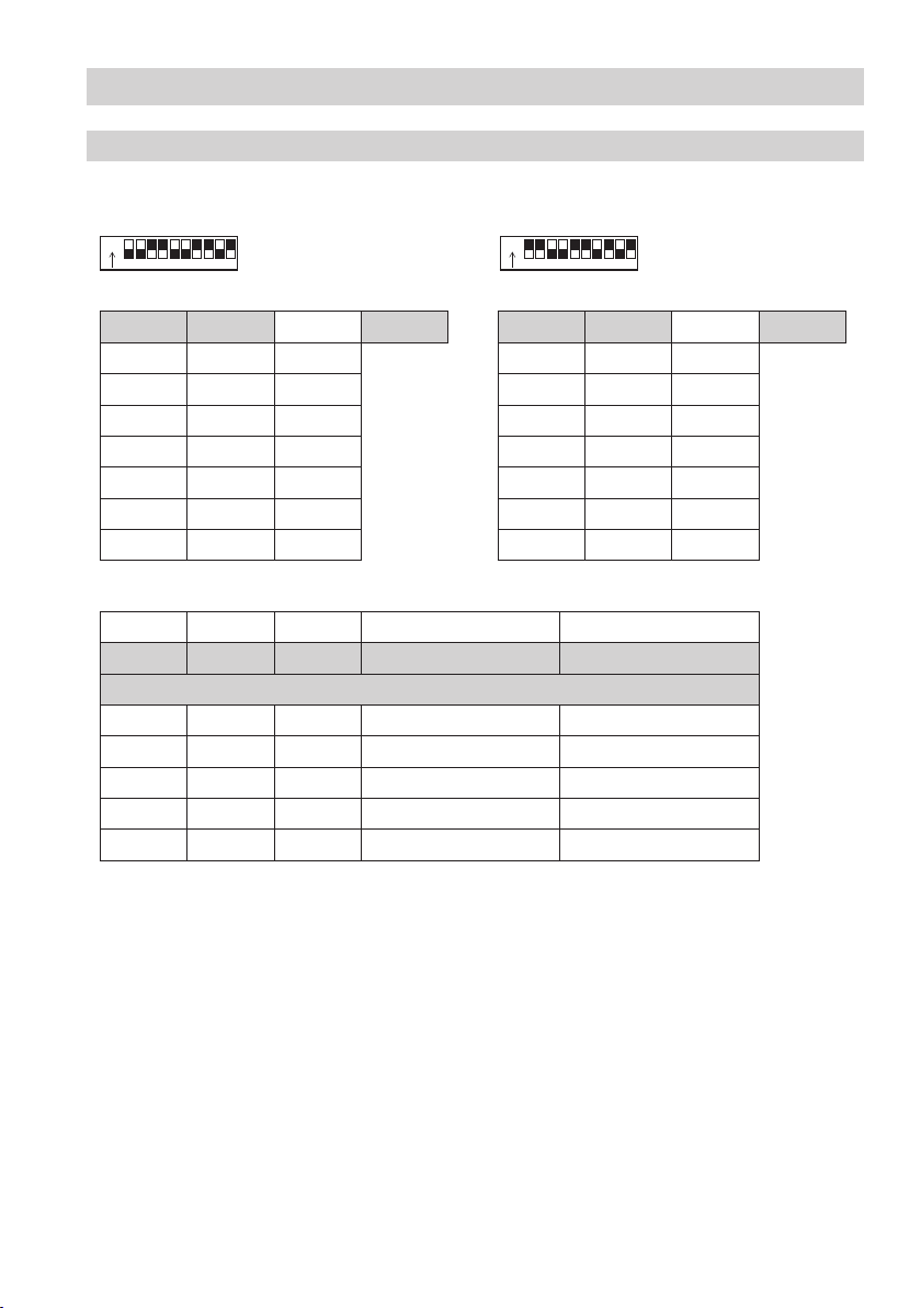
Table “Node ID”
In a CAN bus system a maximum of 123 nodes (devices) can be administered. Each node has its own
address (node ID). This address can be set via a 10-pole code switch
3.
3 3
Code switch, white Code switch, white
Node ID 51
S1
S2
ON 1
ON 2
S3 OFF 4
S4 OFF 8
S5 ON 16
S6 ON 32
S7 OFF 64
(Factory setting)
S1
S2
S3 ON 4
S4 ON 8
S5 OFF 16
S6 OFF 32
S7 ON 64
(Example)
OFF 1
OFF 2
S 8 S 9 S 10 Baud rate Cable length
OFF ON OFF 250 kBit/s 125 m
Factory setting
ON ON OFF 125 kBit/s 250 m
OFF OFF ON 100 kBit/s 335 m
ON OFF ON 50 kBit/s 500 m
OFF ON ON 20 kBit/s 1000 m
ON ON ON 10 kBit/s 1000 m
Node ID 76
31
Page 32

Annex – continued –
Declaration of Conformity
We hereby declare that the equipment LRG 16-40, LRG 17-40 conform to the following European
guidelines:
n LV guideline 73/23/eec version 93/68/eec
n Pressure Equipment Directive (PED) 97/23/EC of 29 May 1997
Applied conformity assessment procedure: Annex III, Module B and D,
verified by notified body 0525
This declaration is no longer valid if modifications are made to the equipment without consultation with
us.
Bremen, 1st December 2005
GESTRA AG
Dipl.-Ing. Uwe Bledschun
(Academically qualified engineer)
Head of Design Dept.
Dipl.-Ing. Lars Bohl
(Academically qualified engineer)
Quality Assurance Representative
32
Page 33

For your notes
33
Page 34

For your notes
34
Page 35

For your notes
35
Page 36

Agencies all over the world:
www.gestra.de
GESTRA
España
GESTRA ESPAÑOLA S.A.
Luis Cabrera, 86-88
E-28002 Madrid
Tel. 00 34 91 / 5 15 20 32
Fax 00 34 91 / 4 13 67 47; 5 15 20 36
E-mail: aromero@flowserve.com
Great Britain
Flowserve Flow Control (UK) Ltd.
Burrel Road, Haywards Heath
West Sussex RH 16 1TL
Tel. 00 44 14 44 / 31 44 00
Fax 00 44 14 44 / 31 45 57
E-mail: gestraukinfo@flowserve.com
Italia
Flowserve S.p.A.
Flow Control Division
Via Prealpi, 30
l-20032 Cormano (MI)
Tel. 00 39 02 / 66 32 51
Fax 00 39 02 / 66 32 55 60
E-mail: infoitaly@flowserve.com
Polska
GESTRA POLONIA Spolka z.o.o.
Ul. Schuberta 104
PL - 80-172 Gdansk
Tel. 00 48 58 / 3 06 10 -02 od 10
Fax 00 48 58 / 3 06 33 00
E-mail: gestra@gestra.pl
Portugal
Flowserve Portuguesa, Lda.
Av. Dr. Antunes Guimarães, 1159
Porto 4100-082
Tel. 0 03 51 22 / 6 19 87 70
Fax 0 03 51 22 / 6 10 75 75
E-mail: jtavares@flowserve.com
USA
Flowserve GESTRA U.S.
2341 Ampere Drive
Louisville, KY 40299
Tel.: 00 15 02 / 502 267 2205
Fax: 00 15 02 / 502 266 5397
E-mail: dgoodwin@flowserve.com
GESTRA AG
P. O. Box 10 54 60, D-28054 Bremen
Münchener Str. 77, D-28215 Bremen
Telephone +49 (0) 421 35 03 - 0
Fax +49 (0) 421 35 03 -393
E-Mail gestra.ag@flowserve.com
Internet www.gestra.de
818524-01/806cm · 2005 GESTRA AG · Bremen · Printed in Germany
36
 Loading...