

Page 1
USER INSTRUCTIONS
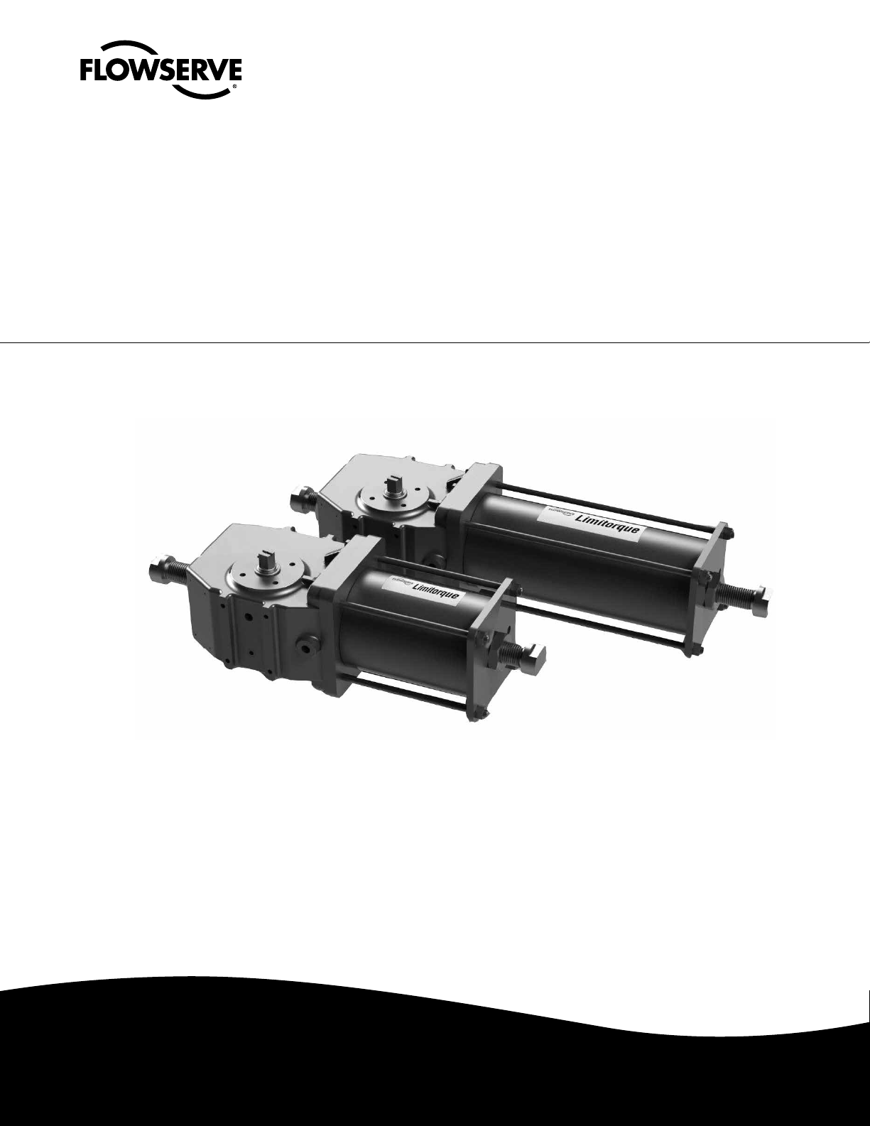
LPC Compact Actuator Series
Single Acting & Double Acting
FCD LFENIM0002-00-AQ – 07/14
Installation
Operation
Maintenance
Experience In Motion
Page 2

LPC Compact Actuator Series FCD LFENIM0002-00-AQ 07/14
Contents
1 Standard Information 3
1.1 General Usage 3
1.2 Terms Concerning Safety 3
1.3 Protective Clothing 4
1.4 Qualified Personnel 4
1.5 Other General Requirements for In-Plant Installation 4
1.6 Spare Parts 4
1.7 Service/Repair 4
1.8 Storage 5
1.9 Valve and Actuator Variations 6
1.10 Unpacking 6
2 Installation Instructions 7
2.1 Valve and Actuator Check 7
2.2 Connection With Valve and Mounting Kit 8
2.3 Travel-stop Bolts and Accessories 8
2.4 Pneumatic Supply Fluids 8
2.5 Initial Operation 9
2.6 Fail Open and Fail Close Configuration 9
3 Field Conversion 11
4 Maintenance Instructions 12
4.1 General Disassembly Instructions 12
4.2 Spring Container and Pneumatic Cylinder Maintenance 12
4.3 Housing and Scotch Yoke Maintenance 14
5 Troubleshooting 15
6 Disposal of Decommissioned Actuators 17
7 Annex 18
Figures
Figure 1: Actuator’s Position on the Wooden Pallet 5
Figure 2: Position of the Output Shaft 5
Figure 3: Standard Data Plate Position 7
Figure 4: Nameplate Sample 7
Figure 5: Actuator Configuration: Fail Close – Fail Clockwise – Single Acting 9
Figure 6: Actuator Configuration: Fail Open – Fail Counter Clockwise – Single Acting 9
Figure 7: Double Acting Actuator Configuration – Close Position 10
Figure 8: Double Acting Actuator Configuration – Open Position 10
Figure 9: Fail Close Configuration With Valve 10
Figure 10: Fail Open Configuration With Valve 10
Figure 11: Model Selection Table 18
Figure 12: Seals Material 18
Figure 13: Weights and Dimensions Table – Single Acting – Symmetric and Canted 20
Figure 14: Weights and Dimensions Table – Double Acting – Symmetric and Canted 21
Figure 15: Exploded View 23
2
Page 3

LPC Compact Actuator Series FCD LFENIM0002-00-AQ 07/14
Standard Information
1
1. Using Flowserve Valves, Actuators and Accessories Correctly
1.1 General Usage
The following instructions are designed to assist in unpacking, installing and performing maintenance as required on
Flowserve products. Product users and maintenance personnel should thoroughly review this bulletin prior to installing,
operating or performing any maintenance.
In most cases Flowserve actuators and accessories are designed for specific applications with regard to medium,
pressure and temperature. For this reason they should not be used in other applications without first contacting the
manufacturer.
1.2 Terms Concerning Safety
The safety terms DANGER, WARNING, CAUTION and NOTE are used in these instructions to highlight particular
dangers and/or to provide additional information on aspects that may not be readily apparent.
DANGER: indicates that death, severe personal injury and/or substantial property damage will occur if proper
c
precautions are not taken.
a WARNING: indicates that death, severe personal injury and/or substantial property damage can occur if proper
precautions are not taken.
a CAUTION: indicates that minor personal injury and/or property damage can occur if proper precautions are not
taken.
NOTE: indicates and provides additional technical information, which may not be very obvious, even to qualified
personnel.
Compliance with other, not particularly emphasized notes, with regard to transport, assembly, operation and maintenance and with regard to technical documentation (e.g. in the operating instruction, product documentation or on
the product itself) is essential, in order to avoid faults, which in themselves might directly or indirectly cause severe
personal injury or property damage.
flowserve.com
3
Page 4

LPC Compact Actuator Series FCD LFENIM0002-00-AQ 07/14
1.3 Protective Clothing
Flowserve products are often used in problematic applications (e.g. extremely high pressures, dangerous, toxic or
corrosive media). When performing service, inspection or repair operations always ensure, that the valve and actuator
are depressurized and that the valve has been cleaned and is free from harmful substances. In such cases pay particular
attention to personal protection (protective clothing, gloves, glasses etc.).
1.4 Qualified Personnel
Qualified personnel are people who, on account of their training, experience and instruction and their knowledge of
relevant standards, specifications, accident prevention regulations and operating conditions, have been authorized by
those responsible for the safety of the plant to perform the necessary work and who can recognize and avoid possible
dangers.
1.5 Other General Requirements for In-Plant Installation
• Pipelines must be correctly aligned to ensure that the valve is not fitted under tension.
• Flowserve can provide a fire protection system. If not expressly agreed, fire protection must be provided by user.
1.6 Spare Parts
Use only Flowserve original spare parts. Flowserve cannot accept responsibility for any damages that occur from using
spare parts or fastening materials from other manufacturers. If Flowserve products (especially sealing materials) have
been on store for longer periods check these for corrosion or deterioration before using these products.
1.7 Service/Repair
To avoid possible injury to personnel or damage to products, safety terms must be strictly adhered to. Modifying
this product, substituting non-factory parts, or using maintenance procedures other than outlined in this instruction
could drastically affect performance and be hazardous to personnel and equipment, and may void existing warranties.
Between actuator and valve there are moving parts. To avoid injury Flowserve provides pinch-point-protection in the
form of cover plates, especially where side-mounted positioners are fitted. These protections are according to Machine
Directive 2006/42/EC recommendations. If these plates are removed for inspection, service or repair special attention
is required. After completing work the cover plates must be refitted. Apart from the operating instructions and the
obligatory accident prevention directives valid in the country of use, all recognized regulations for safety and good
engineering practices must be followed.
a WARNING: Before products are returned to Flowserve for repair or service, Flowserve must be provided
with a certificate which confirms that the product has been decontaminated and is clean. Flowserve will not
accept deliveries if a certificate has not been provided (a form can be obtained from Flowserve).
4
Page 5
LPC Compact Actuator Series FCD LFENIM0002-00-AQ 07/14
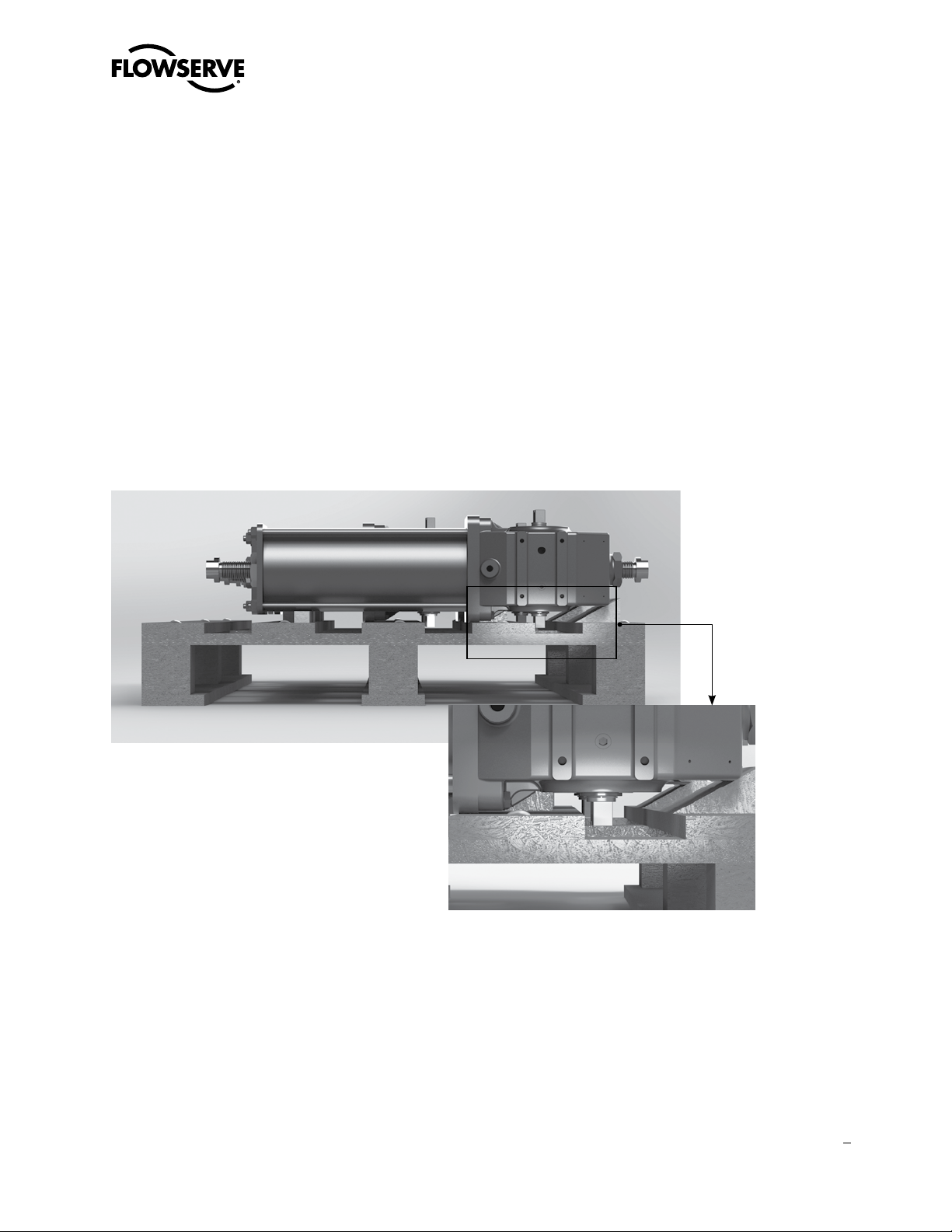
1.8 Storage
In many cases Flowserve products are manufactured from stainless steel. Products not manufactured from stainless
steel are typically provided with an epoxy resin coating or with other painting systems agreed with the customer. This
means that Flowserve products are well protected from corrosion. Nevertheless, in order to maintain good working
conditions and a good finish until the actuator is installed on the plant, it is necessary to follow a few rules during the
storage period:
• Flowserve products must be stored adequately in a clean, dry environment.
• Ensure that plastic caps are fitted to protect the pneumatic connections and the cable entries, to prevent the ingress
of foreign materials. These caps should not be removed until the product is actually mounted into the system.
• If the storage is outdoor, or if long-term storage (more than four months) is necessary, the plastic protection plugs
have to be replaced by metal plugs, because the plastic plugs are not weatherproof function, whereas the metal ones
guarantee a weatherproof protection.
• The actuator must be placed on a wooden pallet, in order to not damage the coupling base and avoid that other
surfaces other surfaces rest on the ground.
Figure 1: Actuator’s Position on the Wooden Pallet
Figure 2: Position of the Output Shaft
In case of long-term storage (more than four months), additionally perform the following measures:
• Coat the coupling parts (spool piece base, flanges, bushings, joints) with protective oil or grease.
• If possible, blank off the spool piece base flange by a protection disk.
• Provide a tarpaulin cover or some other means of protection, especially if the storage is outdoor.
• It is important to periodically operate the actuator with filtered, dehydrated and lubricated air while in a storage.
5
flowserve.com
Page 6

LPC Compact Actuator Series FCD LFENIM0002-00-AQ 07/14
1.9 Valve and Actuator Variations
These instructions cannot claim to cover all details of all possible product variations, nor can they provide information
for every possible example of installation, operation or maintenance. This means that the instructions normally include
only the directions to be followed by qualified personnel where the product is being used for its defined purpose. If
there are any uncertainties in this respect particularly in the event of missing product-related information, clarification
must be obtained via the appropriate Flowserve sales office.
1.10 Unpacking
• Each delivery includes a packing slip. When unpacking, check all delivered actuators and accessories using this
packing slip.
• Report transport damage to the carrier immediately.
• In case of discrepancies, contact your nearest Flowserve location.
• If necessary, retouch minor damage to the paint coating which may have occurred during transport or storage.
NOTE: When the actuator has ATEX or SIL requirements, ensure that the “LPC Series Safety Manual”
(Functional Safety and SIL Certification) and “LPC Series Safety Extract and Instruction Manual” (Explosive
Atmosphere Equipment and ATEX Certification) accompany this manual and are refer to equipment for usage.
6
Page 7
LPC Compact Actuator Series FCD LFENIM0002-00-AQ 07/14
Installation Instructions
2
The LPC range of Limitorque Pneumatic Actuators is a robust, lightweight modular scotch yoke design, available in
both spring return and double acting configurations, with a torque range up to 1600 Nm (1180 ft-lb); contact factory for
lager size. Available with valve interface in compliance with ISO 5211, or customized upon request.
a WARNING! Actuator operation/pressure limitations must be in accordance with Technical Bulletin (LFENTB0002-00)
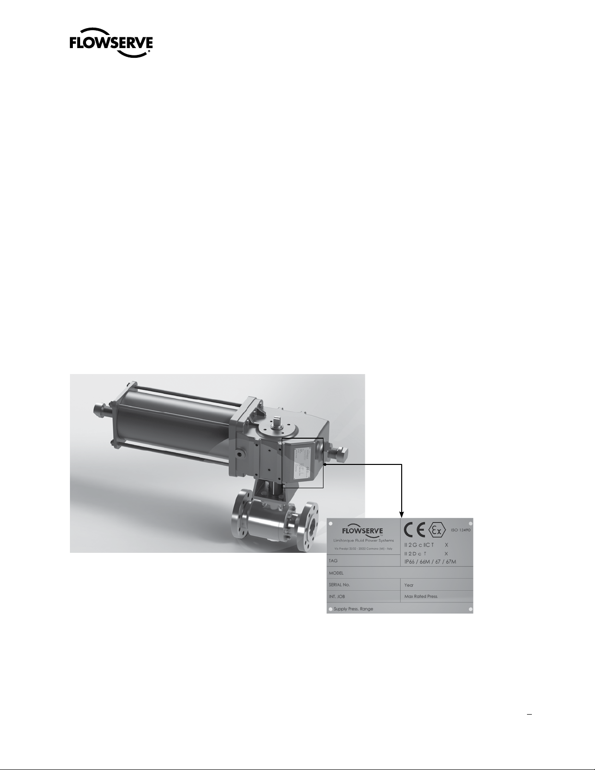
2.1 Valve and Actuator Check
DANGER: Before installation check the order no., serial no., and/or the tag no. to ensure that the valve/actuator is
c
correct for the intended application.
Figure 3: Standard Data Plate Position
Figure 4: Nameplate Sample
Prior to assembly, manually open and close valve (if possible), to ensure freedom of operation. Be sure valve and
Limitorque actuator rotate in the same direction and are in the same position (i.e., valve closed, actuator closed). The
assembly position of the actuator, with reference to the valve, has to be in accordance with the plant requirements
(actuator axis parallel or perpendicular to the pipeline axis).
7
flowserve.com
Page 8

LPC Compact Actuator Series FCD LFENIM0002-00-AQ 07/14
2.2 Connection With Valve and Mounting Kit
The LPC actuator is usually supplied with the spool piece already assembled. To assemble the actuator onto the valve,
perform the following steps:
1. Check the mounting surfaces, the stem adaptor and the spool piece to assure the proper fit. Clean the flange of the
valve and spool piece to remove oils and greases since the torque is transmitted by friction. Also remove any rust
that may have occurred during the storage.
2. Secure the valve in the closed/open position, if possible, with the stem vertical. Lubricate the valve stem in order to
ease the assembly. Place the stem adaptor on the valve stem.
3. Lift the actuator using a proper lifting system. Position the actuator over the valve and lower to engage the stem
adaptor to the actuator bore. Continue to lower until the spool piece sits on valve mounting surface. This coupling
has to take place without force and only with the weight of the actuator. The mounting bolts (or studs) of the valve
should easily fit into the bolt holes of the spool piece without any binding. If needed, turn or stroke the actuator a few
degrees and/or adjust the actuator travel-stops.
4. The mounting nuts (or bolts) connecting the base of the spool piece to the valve flange must be evenly tightened
according to specific tables, available upon request to Flowserve After Sales Department.
2.3 Travel-stop Bolts and Accessories
All actuated valves require accurate travel-stop adjustments at both ends of the stroke to obtain optimum performance
and valve seat life. Adjust the travel-stop bolts of the actuator for the proper open and close valve positions, per valve
manufacturer’s recommendations.
The LPC actuators have travel-stop adjustments in both the clockwise and counter-clockwise directions. The
+/- 5-degree adjustment feature provides shaft rotation from 80 to 100 degrees overall. The adjustment of the travelstops is performed in accordance with the following steps. Refer to Figure 15.
• Pneumatic cylinder stop (19): Loosen the hex nut (20) with a proper wrench. Screw or unscrew the stop (19), using
a proper Allen key, while keeping the hex nut stationary. Tighten the hex nut.
• Housing stop (19): Loosen the hex nut (20) with a proper wrench. Screw or unscrew the stop (19), using a proper
Allen key, while keeping the hex nut stationary. Tighten the hex nut.
Adjust the travel stop bolts of the actuator for the proper open and closed valve positions, per valve manufacturer’s
recommendations. Pneumatically stroke the actuator several times to assure proper operation. If the actuator is
equipped with a switch, positioner or other accessories, adjusts them at this time.
2.4 Pneumatic Supply Fluids
To prolong actuator life use only clean, dry pneumatic supply fluids. Lubricated fluids are not required; however, they
are recommended, particularly for high cycle applications. Do not use lubricated fluids with positioners, as they may
damage the positioner.
8
Page 9

LPC Compact Actuator Series FCD LFENIM0002-00-AQ 07/14
2.5 Initial Operation
Before initial operation of the actuator, perform the following checks:
• Check that all electrical supply, control and signal lines are properly connected, by following the dedicated customer
procedures.
• Check that the pressure and quality of the supply fluids are as prescribed.
• Check the absence of leaks in the pneumatic connections. If necessary tighten the pipe fittings.
2.6 Fail Open and Fail Close Configuration
The actuator is designed for work in both configurations: fail open and fail close. For conversion from one configuration
to the other, refer to next paragraph.
Figure 5: Actuator Configuration: Fail Close – Fail Clockwise – Single Acting
Figure 6: Actuator Configuration: Fail Open – Fail Counter Clockwise – Single Acting
9
flowserve.com
Page 10

LPC Compact Actuator Series FCD LFENIM0002-00-AQ 07/14
Figure 7: Double Acting Actuator Configuration – Close Position
10
Figure 8: Double Acting Actuator Configuration – Open Position
Figure 9: Fail Close Configuration With Valve Figure 10: Fail Open Configuration With Valve
Page 11

LPC Compact Actuator Series FCD LFENIM0002-00-AQ 07/14
Field Conversion
3
For field conversion from fail open (CCW) to fail close (CW) and vice versa, follow the following steps.
NOTE:
• An additional adapter kit is not required for field conversion
• Disassemble the actuator from the valve before carrying out the conversion
THE ACTUATOR IS DISASSEMBLED FROM THE VALVE
a WARNING: Ensure that the pneumatic connection ports of the cylinder are disconnected. Also make sure that
all pneumatic supplies to the control unit and all power supplies are disconnected. Finally, make sure that the
actuator is in fail position.
3.0.1 Starting with the actuator in a fail open (CCW) execution,
remove the actuator from the valve, keeping the spool
adaptor installed onto the valve.
3.0.2 Rotate the actuator.
3.0.3 Reassemble in the new position the actuator onto
the spool piece and the valve. Now the actuator is in
a fail close (CW) execution. Similar steps will apply for
conversion from fail close (CW) to fail open (CCW).
flowserve.com
11
Page 12

LPC Compact Actuator Series FCD LFENIM0002-00-AQ 07/14
Maintenance Instructions
4
LPC series compact actuators are designed to offer the greatest ease of operations of assembly, disassembly and maintenance. The maintenance and disassembly do not require special equipment or special or large wrenches. Furthermore
the joints among the moving parts of the actuator are made exclusively through pins and then not using bolts to be
tightened with specific torques.
LPC compact actuators do not need maintenance for a long period, even if they are working in severe condition. The
lifetime of these actuators is guaranteed for 25 years with a regular and programmed maintenance operation every five
years. However, if the actuator operation happens infrequently, it is recommended to periodically check the actuator by
performing the following steps:
• In the plants, where it is possible, carry out a few opening and closing operations, involving all the control unit
components, checking that the actuator operates correctly and within the required stroking times.
• Check that all the signals (pneumatic and electric) arriving at the actuator are correct and that the supply fluid pressure is within the required range. Check for the absence of leaks in the pneumatic connections. If necessary, tighten
the pipe fittings.
• Check the paint coating. If some areas are damaged due to accidental events, retouch them according to paint
procedure supplied along with the actuator documentation.
In case of scheduled preventive maintenance, or following accidental events, refer to the following maintenance
instructions regarding the main actuators components (pneumatic cylinder and housing).
4.1 General Disassembly Instructions
1. Disconnect all air and electrical supplies from actuator;
2. If removal of the actuator from valve is necessary, before dismounting the actuator, remove all accessories from
actuator.
3. The reference drawings for the instructions reported in the following paragraphs are exploded views of single acting
and double acting actuators, included as Figures 15.
4.2 Spring Container and Pneumatic Cylinder Maintenance
The pneumatic cylinder maintenance mainly consists in the replacement of all parts that may degrade in the course of
time, even in the absence of faults. These components are the o-rings and the sliding elements of the piston.
12
NOTE: In the LPC Compact Actuator Series, in single acting execution, the spring is located inside the
pneumatic cylinder, as shown in Figures 5 and 6.
a WARNING: Ensure that the pneumatic connection ports of the cylinder are disconnected. Also make sure that
all pneumatic supplies to the control unit and all power supplies are disconnected. Finally, make sure that
the actuator is in fail position, i.e. that it is not locked in a position with the spring compressed by means of
locking devices.
Page 13

LPC Compact Actuator Series FCD LFENIM0002-00-AQ 07/14
Standard in-field maintenance
Perform the following steps with reference to Figure 15:
4.2.1 Unscrew and remove the travel stop of the pneumatic
cylinder (19). For removing the stop, refer to the indications
given in paragraph 2.3.
4.2.2 Remove four tie rods (16) positioned on the cylinder by
unscrewing the nuts (18) on the sides of the End Flange and
unscrewing the tie rods from the adaptor flange (26).
4.2.3 Remove carefully the end flange (23) from the can (17).
Remove the two o-ring (21 and 22) from the end flange.
4.2.4 Finally remove the can (17) without damaging or scratching
the inner surface.
4.2.5 Remove the o-ring (25) and finally the two guide-tapes (36)
from the piston (15). Clean all the surface of piston and flanges in
contact with these components with a clean rag and solvent
compatible with o-ring material (for information contact Flowserve).
Brush the o-rings grooves with a light oil film and install the
new o-rings. Spread a thin layer of oil on the bottom of the guide
tape grooves and install a new guide tapes. Clean the internal
surface of the tube and lubricate with a protective oil film.
4.2.6 Reassemble the parts of the cylinder with reverse procedure as
described in points 3.2.1 to 3.2.4. The tie rods should be tightened
using a torque wrench, applying a torque in accordance with
specific tables, available upon request to Flowserve After
Sales Department.
4.2.7 Readjust the travel stops as instructed in paragraph 2.3.
NOTE: After the standard maintenance steps, stroke the actuator a few times to check for normal operation.
13
flowserve.com
Page 14

LPC Compact Actuator Series FCD LFENIM0002-00-AQ 07/14
4.3 Housing and Scotch Yoke Maintenance
Standard maintenance of the housing may take place in the field.
Standard in–field maintenance
A first standard maintenance is available unscrewing the housing stop bolt (11) and applies a film of grease (with an
applicator) directly on the yoke’s sliding surface.
NOTE: Take note of the length of the stop bolt before making the standard maintenance
and reassemble it at the same length.
Extensive maintenance
If it is necessary to carry out an extra-maintenance inside the housing, perform the following steps:
a WARNING: Ensure that the pneumatic connection ports of the cylinder are disconnected. Also make
sure that all pneumatic supplies to the control unit and all power supplies are disconnected. Finally,
make sure that the actuator is in fail position, i.e. that it is not locked in a
position with the spring compressed by means of locking devices.
4.3.1 Remove the actuator from the valve.
4.3.2 Remove the pneumatic cylinder unscrewing the six screws (29)
and unbolting the piston rod (11) to the guide block (13).
4.3.3 Unscrew the screw locates on the left of the housing stop bolt (33),
remove the flat washer (32) and remove the guide bar (10).
Remove the o-ring (9).
4.3.4 Remove the retaining rings (5), the bushes (4) and the o-rings (31),
unscrew the caps (2) and finally unscrew the two bolts (1). Now, pull
out the output shaft (28) from the housing (30).
4.3.5 Remove the scotch yoke (3) from the housing, unscrew
upper and lower screws (6) and pull out the two washers (7)
and roller bearings (8).
14
4.3.6 Apply a grease film on the slider surface of the yoke wings (3) and
the roller bearings (8) (For the grease characteristics refer to Grease
Characteristics Table, available upon request to Flowserve After
Sales Department). Replace the o-ring (9).
4.3.7 Reassemble the parts of the housing using a reverse
procedure as previously described.
Page 15

LPC Compact Actuator Series FCD LFENIM0002-00-AQ 07/14
Troubleshooting
5
To prevent the actuator from not proper functioning or low performance, first ensure that the installation and the adjustment operations are carried out completely in accordance with this manual.
a WARNING: During the activities of identifying faults, it is very important to observe all the regulations and
instructions about safety. Read all the paragraphs of this manual concerning maintenance before opening for
inspection or starting to repair any actuator components. If in doubt, choose SAFETY FIRST.
You can identify the causes of possible malfunctions with the help of the following table (“troubleshooting table”). If a
malfunction cannot be identified and eliminated using the table, Flowserve Service Department should be contacted.
Troubleshooting Table
Problem Possible cause Solution
Check that all the pneumatic connections and
that all the pneumatic components have been
installed correctly, and are in accordance with the
Actuator has not been properly installed.
Supply pressure problems.
Problems in the control panel (if present).
The actuator does not move.
The valve is blocked.
Exhaust port(s) obstructed.
Problems with lubricants.
actuator operating mode.
Check that the actuator is properly connected to
the valve and that there aren’t problems in the
mounting kit.
Check that the actuator is properly connected to
the valve and that there aren’t problems in the
mounting kit.
Check the correct functioning of the control
panel. In particular, check all the pneumatic and
electric connections.
Check the correct level of supply voltage for
solenoid valves and other electrical/electronic
components.
Check that valve is free to rotate. If necessary
disassemble the actuator from the valve.
Screw cap(s) must be disengaged. Ensure vent
ports are free. If not, clean them of any obstructions and clean the dust excluders, if present.
Ensure that the actuator is properly lubricated,
and that there is no solidified grease among
sliding parts or rotating parts. If actuator
lubrication is inadequate or improper, apply a
uniform lubricant layer. Follow the instructions
for cylinder maintenance (par. 4.2). Consult
Flowserve for proper oil and grease to be used.
flowserve.com
15
Page 16

LPC Compact Actuator Series FCD LFENIM0002-00-AQ 07/14
Troubleshooting Table
Problem Possible cause Solution
Check if any moving part is blocked. If so,
A moving part is seized up.
Leakage of the pneumatic cylinder.
The actuator model is not the correct one,
The actuator does not move.
The valve does not fully perform
the stroke, during opening or
closing.
During the stroke the actuator
exhibits excessive amounts of
backlash.
In case of other problems not listed in this table, you should contact Flowserve Service Department.
or is not suitable for the plant conditions.
Spring problems (if actuator is a single
acting model).
A lockout device has been inserted and
forgotten in that position.
The actuator is not correctly adjusted.
Exhaust port(s) obstructed.
Actuator torque lower than required.
Some components are excessively worn.
follow the maintenance instructions given in the
relevant paragraphs of this manual or in special
maintenance operating instructions.
A significant air leak may prevent the actuator
from operating. Ensure that there aren’t any leaks
in the pneumatic cylinder toward the outside. If
possible, detect them using a leak finder spray.
Check also that there are not leaks across the
piston. If leaks are present, follow the cylinder
maintenance instructions given in paragraph 3.2.
Check the actuator nameplate and the plant
requirements. If there are mismatches, contact
Flowserve Service Department.
Check the proper functioning of the spring can.
If problems are found, contact Flowserve Service
Department.
Perform the following test: disassemble the
actuator from the valve and measure the
minimum pressure values necessary to move
and compress the spring. Compare the measured
values with the ones reported on the Testing
Certificate. If there are significant differences you
should contact Flowserve Service Department.
Disconnect the lockout module.
As above, check the position of the stoppers
in opening and closing direction. If necessary
adjust them. Follow the instructions given in
paragraph 2.3.
Screw cap(s) must be disengaged. Ensure vent
port are free. If not, clean them of any obstruction and clean the dust excluders, if present.
In order to do a check it is necessary to perform
the following test: disassemble the actuator from
the valve and measure the minimum pressure
values necessary to move and compress the
spring (if the actuator is a single acting model)
or the minimum values necessary to move the
actuator yoke and perform a stroke (for double
acting models). Compare the measured values
with the ones reported on the Testing Certificate.
If there are significant differences you should
contact Flowserve Service Department.
Identify and replace these components,
according to the procedure described in the
relevant paragrahs of this manual, or in special
maintenance operating instructions.
16
Page 17

LPC Compact Actuator Series FCD LFENIM0002-00-AQ 07/14
Disposal of
Decommissioned
6
Actuators
Actuators that are to be decommissioned permanently due to a plant closure or for another reason must have the
stored energy in the spring neutralized. This can be done in several ways:
• Decommissioning by filling with concrete – following proper removal of the actuator from any hazardous areas,
the spring module may be neutralized by cutting a small opening in the end or side of the spring can and filling
the spring can with liquid concrete and allowing the concrete to dry. This will eliminate any possibility of spring
decompression if it were to be removed from the actuator without following proper procedures.
• Decommissioning by cutting the spring – following proper removal of the actuator from any hazardous areas, the
spring module may be neutralized by cutting a small opening in the side of the spring can and accessing the spring
coils. The spring coils are then cut using a torch to relieve all compression and stored energy. Care should be taken
that the opening in the spring can is sufficiently small to prevent any pieces of the spring from escaping when the
spring is cut.
a WARNING: Failure to neutralize the spring in the actuator or to follow these instructions could lead to injury to
personnel or property damage.
Either method is acceptable to Flowserve although the method outlined in the first point is preferred, as the stored
energy in the spring is not suddenly released when the spring is cut. Hence, this is the safest method.
No actions need be taken on any other portions of the actuator to decommission it.
flowserve.com
17
Page 18

7
CENTERBODY
DOUBLE
ACTING
SEALMATERIAL
SINGLE
ACTING
LPCACTUATORS:NOMENCLATURE
LPC10X
SR01
160Y
SPRINGCANSIZE
YOKETYPE
PNEUMATICCYLINDERSIZE
example model n°
LPC Compact Actuator Series FCD LFENIM0002-00-AQ 07/14
Annex
SELECTIONTABLE
examplemodeln°
05
10
SIZE
Figure 11: Model Selection Table
Code Material Temperature Range Climate Classification According to IEC60721
B Buna Std Temp: -29°C to +100°C (-20°F to 212°F)
V Viton Hi Temp: up to +160°C (320°F)
S Silicon Low Temp: down to -40°C (-40°F) Temperate
Z Other Special Applications - Consult Factory Cold & Polar
Figure 12: Seals Material
A
B
080 BBUNA
100
120
140
160
180
200
220
VVITON
SSILICON
ZSPECIAL
SRSPRINGRETURN
DADOUBLEACTING
Tropical & Arid
01
02
03
04
05
06
18
Page 19

LPC Compact Actuator Series FCD LFENIM0002-00-AQ 07/14
TOLERANCE ±10% TO BE CONSIDERED ON DIMENSIONS
Dimensions mm (in) - Kg (lbs)
Model A B D E K H L Q Z 'N' NPT PORT Weight
LPC-05X-080Y-SR01
LPC-05X-080Y-SR02
LPC-05X-100Y-SR01
LPC-05X-100Y-SR02
LPC-05X-100Y-SR03
LPC-05X-120Y-SR01
LPC-05X-120Y-SR02
LPC-05X-120Y-SR03
LPC-05X-120Y-SR04
LPC-05X-120Y-SR05
LPC-05X-140Y-SR01
LPC-05X-140Y-SR02
LPC-05X-140Y-SR03
LPC-05X-140Y-SR04
LPC-05X-140Y-SR05
LPC-05X-140Y-SR06
LPC-05X-160Y-SR01
LPC-05X-160Y-SR02
LPC-05X-160Y-SR03
LPC-05X-160Y-SR04
LPC-05X-160Y-SR05
LPC-05X-160Y-SR06
716 178 100 438 38 175 69 120 140
28.19 7.01 3.94 17.24 1.50 6.89 2.72 4.72 5.51 82
716 178 100 438 38 175 69 120 140
28.19 7.01 3.94 17.24 1.50 6.89 2.72 4.72 5.51 83
716 178 100 438 38 175 69 140 140
28.19 7.01 3.94 17.24 1.50 6.89 2.72 5.51 5.51 94
716 178 100 438 38 175 69 140 140
28.19 7.01 3.94 17.24 1.50 6.89 2.72 5.51 5.51 95
716 178 100 438 38 175 69 140 140
28.19 7.01 3.94 17.24 1.50 6.89 2.72 5.51 5.51 96
716 178 100 438 38 175 69 150 140
28.19 7.01 3.94 17.24 1.50 6.89 2.72 5.91 5.51 97
716 178 100 438 38 175 69 150 140
28.19 7.01 3.94 17.24 1.50 6.89 2.72 5.91 5.51 98
716 178 100 438 38 175 69 150 140
28.19 7.01 3.94 17.24 1.50 6.89 2.72 5.91 5.51 99
716 178 100 438 38 175 69 150 140
28.19 7.01 3.94 17.24 1.50 6.89 2.72 5.91 5.51 100
716 178 100 438 38 175 69 150 140
28.19 7.01 3.94 17.24 1.50 6.89 2.72 5.91 5.51 102
716 178 100 438 38 175 69 165 140
28.19 7.01 3.94 17.24 1.50 6.89 2.72 6.50 5.51 104
716 178 100 438 38 175 69 165 140
28.19 7.01 3.94 17.24 1.50 6.89 2.72 6.50 5.51 106
716 178 100 438 38 175 69 165 140
28.19 7.01 3.94 17.24 1.50 6.89 2.72 6.50 5.51 107
716 178 100 438 38 175 69 165 140
28.19 7.01 3.94 17.24 1.50 6.89 2.72 6.50 5.51 108
716 178 100 438 38 175 69 165 140
28.19 7.01 3.94 17.24 1.50 6.89 2.72 6.50 5.51 110
716 178 100 438 38 175 69 165 140
28.19 7.01 3.94 17.24 1.50 6.89 2.72 6.50 5.51 119
716 178 100 438 38 185 69 185 140
28.19 7.01 3.94 17.24 1.50 7.28 2.72 7.28 5.51 117
716 178 100 438 38 185 69 185 140
28.19
28.19 7.01 3.94 17.24 1.50 7.28 2.72 7.28 5.51 119
28.19 7.01 3.94 17.24 1.50 7.28 2.72 7.28 5.51 120
28.19 7.01 3.94 17.24 1.50 7.28 2.72 7.28 5.51 122
28.19 7.01 3.94 17.24 1.50 7.28 2.72 7.28 5.51 126
7.01 3.94 17.24 1.50 7.28 2.72 7.28 5.51 118
716 178 100 438 38 185 69 185 140
716 178 100 438 38 185 69 185 140
716 178 100 438 38 185 69 185 140
716 178 100 438 38 185 69 185 140
1/4"
1/4"
1/4"
1/4"
1/4"
1/4"
1/4"
1/4"
1/4"
1/4"
1/4"
1/4"
1/4"
1/4"
1/4"
1/4"
1/4"
1/4"
1/4"
1/4"
1/4"
1/4"
37
38
43
43
44
44
44
45
45
46
47
48
48
49
50
54
53
54
54
55
56
57
19
flowserve.com
Page 20

20
LPC Compact Actuator Series FCD LFENIM0002-00-AQ 07/14
TOLERANCE ±10% TO BE CONSIDERED ON DIMENSIONS
Dimensions mm (in) - Kg (lbs)
Model A B D E K H L Q Z 'N' NPT PORT Weight
LPC-10X-100Y-SR01
LPC-10X-120Y-SR01
LPC-10X-120Y-SR02
LPC-10X-140Y-SR01
LPC-10X-140Y-SR02
LPC-10X-140Y-SR03
LPC-10X-160Y-SR01
LPC-10X-160Y-SR02
LPC-10X-160Y-SR03
LPC-10X-160Y-SR04
LPC-10X-160Y-SR05
LPC-10X-180Y-SR01
LPC-10X-180Y-SR02
LPC-10X-180Y-SR03
LPC-10X-180Y-SR04
LPC-10X-180Y-SR05
LPC-10X-180Y-SR06
LPC-10X-200Y-SR01
LPC-10X-200Y-SR02
LPC-10X-200Y-SR03
LPC-10X-200Y-SR04
LPC-10X-200Y-SR05
LPC-10X-200Y-SR06
LPC-10X-220Y-SR01
LPC-10X-220Y-SR02
LPC-10X-220Y-SR03
LPC-10X-220Y-SR04
LPC-10X-220Y-SR05
LPC-10X-220Y-SR06
844 240 132 472 50 245 105 140 172
33.23 9.45 5.20 18.58 1.97 9.65 4.13 5.51 6.77 149
844 240 132 472 50 245 105 165 172
33.23 9.45 5.20 18.58 1.97 9.65 4.13 6.50 6.77 159
844 240 132 472 50 245 105 165 172
33.23 9.45 5.20 18.58 1.97 9.65 4.13 6.50 6.77 163
844 240 132 472 50 245 105 165 172
33.23 9.45 5.20 18.58 1.97 9.65 4.13 6.50 6.77 169
844 240 132 472 50 245 105 165 172
33.23 9.45 5.20 18.58 1.97 9.65 4.13 6.50 6.77 174
887 240 132 515 50 245 105 165 172
34.92 9.45 5.20 20.28 1.97 9.65 4.13 6.50 6.77 179
844 240 132 472 50 245 105 185 172
33.23 9.45 5.20 18.58 1.97 9.65 4.13 7.28 6.77 175
844 240 132 472 50 245 105 185 172
33.23 9.45 5.20 18.58 1.97 9.65 4.13 7.28 6.77 178
887 240 132 515 50 245 105 185 172
34.92 9.45 5.20 20.28 1.97 9.65 4.13 7.28 6.77 183
887 240 132 515 50 245 105 185 172
34.92 9.45 5.20 20.28 1.97 9.65 4.13 7.28 6.77 188
923 240 132 551 50 245 105 185 172
36.34 9.45 5.20 21.69 1.97 9.65 4.13 7.28 6.77 192
844 240 132 472 50 245 105 230 172
33.23 9.45 5.20 18.58 1.97 9.65 4.13 9.06 6.77 199
844 240 132 472 50 245 105 230 172
33.23 9.45 5.20 18.58 1.97 9.65 4.13 9.06 6.77 202
887 240 132 515 50 245 105 230 172
34.92 9.45 5.20 20.28 1.97 9.65 4.13 9.06 6.77 206
887 240 132 515 50 245 105 230 172
34.92 9.45 5.20 20.28 1.97 9.65 4.13 9.06 6.77 211
923 240 132 551 50 245 105 230 172
36.34 9.45 5.20 21.69 1.97 9.65 4.13 9.06 6.77 215
923 240 132 551 50 245 105 230 172
36.34 9.45 5.20 21.69 1.97 9.65 4.13 9.06 6.77 219
844 240 132 472 50 245 105 245 172
33.23
33.23 9.45 5.20 18.58 1.97 9.65 4.13 9.65 6.77 221
34.92 9.45 5.20 20.28 1.97 9.65 4.13 9.65 6.77 226
34.92 9.45 5.20 20.28 1.97 9.65 4.13 9.65 6.77 231
36.34 9.45 5.20 21.69 1.97 9.65 4.13 9.65 6.77 234
36.34 9.45 5.20 21.69 1.97 9.65 4.13 9.65 6.77 241
33.23 9.45 5.20 18.58 1.97 9.65 4.13 9.65 6.77 254
33.23 9.45 5.20 18.58 1.97 9.65 4.13 9.65 6.77 257
34.92 9.45 5.20 20.28 1.97 9.65 4.13 9.65 6.77 261
34.92 9.45 5.20 20.28 1.97 9.65 4.13 9.65 6.77 266
36.34 9.45 5.20 21.69 1.97 9.65 4.13 9.65 6.77 269
36.34 9.45 5.20 21.69 1.97 9.65 4.13 9.65 6.77 273
9.45 5.20 18.58 1.97 9.65 4.13 9.65 6.77 218
844 240 132 472 50 245 105 245 172
887 240 132 515 50 245 105 245 172
887 240 132 515 50 245 105 245 172
923 240 132 551 50 245 105 245 172
923 240 132 551 50 245 105 245 172
844 240 132 472 50 245 105 245 172
844 240 132 472 50 245 105 245 172
887 240 132 515 50 245 105 245 172
887 240 132 515 50 245 105 245 172
923 240 132 551 50 245 105 245 172
923 240 132 551 50 245 105 245 172
1/4"
1/4"
1/4"
1/4"
1/4"
1/4"
1/4"
1/4"
1/4"
1/4"
1/4"
1/4"
1/4"
1/4"
1/4"
1/4"
1/4"
1/4"
1/4"
1/4"
1/4"
1/4"
1/4"
1/4"
1/4"
1/4"
1/4"
1/4"
1/4"
68
72
74
77
79
81
79
81
83
85
87
90
92
93
96
97
99
99
100
102
105
106
109
115
117
119
121
122
124
Figure 13: Weights and Dimensions Table – Single Acting – Symmetric and Canted
Page 21

LPC Compact Actuator Series FCD LFENIM0002-00-AQ 07/14
TOLERANCE ±10% TO BE CONSIDERED ON DIMENSIONS
Dimensions mm (in) - Kg (lbs)
Model A B D E K H L Q Z
LPC-05X-080Y-DA
LPC-05X-100Y-DA
LPC-05X-120Y-DA
LPC-05X-140Y-DA
LPC-05X-160Y-DA
LPC-10X-100Y-DA
LPC-10X-120Y-DA
LPC-10X-140Y-DA
LPC-10X-160Y-DA
LPC-10X-180Y-DA
LPC-10X-200Y-DA
LPC-10X-220Y-DA
568 178 100 290 38 175 69 120 140
22.36 7.01 3.94 11.42 1.50 6.89 2.72 4.72 5.51 72
568 178 100 290 38 175 69 140 140
22.36 7.01 3.94 11.42 1.50 6.89 2.72 5.51 5.51 87
568 178 100 290 38 175 69 150 140
22.36 7.01 3.94 11.42 1.50 6.89 2.72 5.91 5.51 88
568 178 100 290 38 175 69 165 140
22.36 7.01 3.94 11.42 1.50 6.89 2.72 6.50 5.51 94
568 178 100 290 38 185 69 185 140
22.36 7.01 3.94 11.42 1.50 7.28 2.72 7.28 5.51 103
713 250 130 333 50 245 105 140 172
28.07 9.84 5.12 13.11 1.97 9.65 4.13 5.51 6.77 123
713 250 130 333 50 245 105 165 172
28.07 9.84 5.12 13.11 1.97 9.65 4.13 6.50 6.77 132
713 250 130 333 50 245 105 165 172
28.07 9.84 5.12 13.11 1.97 9.65 4.13 6.50 6.77 138
713 250 130 333 50 245 105 185 172
28.07 9.84 5.12 13.11 1.97 9.65 4.13 7.28 6.77 147
713 250 130 333 50 245 105 230 172
28.07 9.84 5.12 13.11 1.97 9.65 4.13 9.06 6.77 162
713 250 130 333 50 245 105 245 172
28.07 9.84 5.12 13.11 1.97 9.65 4.13 9.65 6.77 165
713 250 130 333 50 245 105 245 172
28.07 9.84 5.12 13.11 1.97 9.65 4.13 9.65 6.77 179
'N' NPT
PORT
1/4" 1/4"
1/4" 1/4"
1/4" 1/4"
1/4" 1/4"
1/4" 1/4"
1/4" 1/4"
1/4" 1/4"
1/4" 1/4"
1/4" 1/4"
1/4" 1/4"
1/4" 1/4"
1/4" 1/4"
'P' NPT
PORT
Weight
33
39
40
43
47
56
60
63
67
73
75
81
21
Figure 14: Weights and Dimensions Table – Double Acting – Symmetric and Canted
flowserve.com
Page 22

19
LPC Compact Actuator Series FCD LFENIM0002-00-AQ 07/14
4
31
Single Acting
38
33
30
32
28
29
26
9
6
34
8
7
35
2
27
22
Number Description Qt y.
1 Bolt 2
2 Cap 2
3 Scotch Yoke 1
4 Bush 2
5 Retaining Ring 2
6 Screw 2
7 Washer 2
1
13
3
Number Description Qt y.
8 Roller Bearing 2
9 O-Ring 1
10 Guide Bar 1
11 Piston Rod 1
12 Pin 2
13 Guide Block 1
14 Bushing 2
11
14
22
12
10
Number Description Qt y.
15 Piston 1
16 Tie Rod 4
17 Spring Can 2
18 Hex Nut 4
19 Stop Bolt 2
20 Hex Nut 2
21 O-Ring 2
Page 23

LPC Compact Actuator Series FCD LFENIM0002-00-AQ 07/14
25
24
25
22
26
Double Acting
16
17
11
24
15
36
23
21
20
18
19
37
36
16
15
Number Description Qt y.
22 O-Ring 1
23 End Flange 1
24 O-Ring 1
25 O-Ring 1
26 Adaptor Flange 1
27 Yoke Pin 1
28 Output Shaft 1
17
23
22
Number Description Qt y.
29 Screw 6
30 Housing 1
31 O-Ring 2
32 Flat Washer 1
33 Screw 1
34 Bushing 1
35 Spring 1
21
19
20
18
Figure 15: Exploded View
Number Description Qt y.
36 Guide Ring 2
37 Bar Pin 8
38 Bushing 1
23
flowserve.com
Page 24

FCD LFENIM0002-00-AQ 07/14 © 2014 Flowserve Corporation.
To find your local Flowserve representative
or for more information about Flowserve Corporation, visit
www.flowserve.com.
Flowserve Limitorque
Fluid Power Systems
Product Sales
Via Rio Vallone 17
20883 Mezzago (MB), Italy
Phone: +39 039 62060 1
Fax: +39 039 62060 213
Email: lfpsinfo@flowserve.com
Flowserve Limitorque
Fluid Power Systems
Manufacturing and Operations
Via Rio Vallone 17
20883 Mezzago (MB), Italy
Phone: +39 039 62060 1
Fax: +39 039 62060 213
Email: lfpsinfo@flowserve.com
Flowserve Limitorque
Fluid Power Systems
Research and Development
Viale dell’Artigianato 24
29122 Piacenza (PC), Italy
Email: lfpsinfo@flowserve.com
Flowserve Corporation has established industry leadership in the design and manufacture of its products. When properly selected, this Flowserve product is designed to perform its intended
function safely during its useful life. However, the purchaser or user of Flowserve products should be aware that Flowserve products might be used in numerous applications under a wide
variety of industrial service conditions. Although Flowserve can (and often does) provide general guidelines, it cannot provide specific data and warnings for all possible applications. The purchaser/user must therefore assume the ultimate responsibility for the proper sizing and selection, installation, operation, and maintenance of Flowserve products. The purchaser/user should
read and understand the Installation Operation Maintenance (IOM) instructions included with the product, and train its employees and contractors in the safe use of Flowserve products in
connection with the specific application.
While the information and specifications contained in this literature are believed to be accurate, they are supplied for informative purposes only and should not be considered certified or as
a guarantee of satisfactory results by reliance thereon. Nothing contained herein is to be construed as a warranty or guarantee, express or implied, regarding any matter with respect to this
product. Because Flowserve is continually improving and upgrading its product design, the specifications, dimensions and information contained herein are subject to change without notice.
Should any question arise concerning these provisions, the purchaser/user should contact Flowserve Corporation at any one of its worldwide operations or offices.
© 2014 Flowserve Corporation, Irving, Texas, USA. Flowserve is a registered trademark of Flowserve Corporation.
flowserve.com
 Loading...