

Page 1

Valtek Logix 1200e/1210e
Digital Positioner
GENERAL INFORMATION
The following instructions are designed to assist in
unpacking, installing and pe rforming maintenanc e as
required on Valtek
Series 1000 is the term used for all the positioners
herein; however, specific numbers indicate features
specific to a model (i .e. Logix 1200 e indicat es th at the
positioner uses HART
maintenance per sonnel should thorou ghly review this
bulletin prior to inst allin g, operating, or per forming any
maintenance on the valve.
Separate Valtek Flow Control Products Installation,
Operation, Maintenance instructions cover the valve
(such as IOM 1 or IOM 27) and actuator (such as IOM
2 or IOM 31) por tio ns of the system and o ther accessories. Refer to the appropria te instruc tions when this
information is needed.
WARNING: To avoid possible injury to personnel or damage to valve parts, users must
strictly adhere to WARNING and CAUTION
notes. Modifying this product, substituting
non-factory or inferior parts, or using maintenance procedures other than outlined could
drastically affect performance and be hazardous to personnel and equipment, and may
void existing warranties.
®
Logix® 1200e digital positioners.
®
protocol). Product users and
WARNING: Standard industry safety practices
must be adhered to when working on this or any
process control product. Specifically, personal
protective and lifting devices must be used as warranted.
Valve and Instrumentation Storage Procedures
Storage
Control valve packages (a control valve and its instrumentation) can be safely stored in an enc losed building that affords environmental protection; heating is
not required. Contr ol valve packages must be stored
on suitable skids, not directl y o n th e fl oor. The storage
location must also be free from flooding, dust, dirt, etc.
Pre-installation Inspection
If a valve control package has been stored for more
than one year, inspect one actuator by disassembling
it per the appropriate
Maintenance In struct ions
tion. If O-rings are out-of-r ound, deter iorated, or both ,
they must be replaced and the actuator rebuilt. All
actuators must then be disassembled and inspected. If
the actuator O-rings are replaced, complete the following steps:
1. Replace the pressure-balanced plug O-rings.
2. Inspect the solenoi d and positioner so ft goods and
replace as necessary.
Installation, Operation, and
(IOM) pr ior to valve inst alla-
Valtek SKU 138430 44-1
Page 2
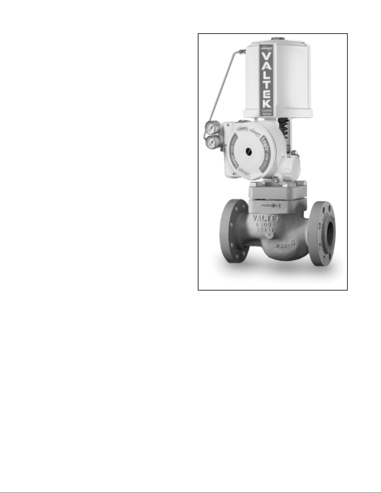
Table of Contents
General Information ...................................................1
Valve and Instrumentation Storage Procedures....1
Logix 1200e Positioner Overview...............................3
Specifications.............................................................3
Positioner Operation...................................................4
Detailed Sequence of Positioner Operations.........4
Logix 1000 Series Positioner Vented-design
Conversion.................................................................5
Tubing Positioner to Actuator ................................ 6
Wiring and Grounding Guidelines..........................6
Available Spare Part Kits for Logix 1200e digital
postioner.............................................................. 22
4 to 20 mA Analog Output Retrofit.......................24
General Information.............................................24
Calibration............................................................25
Troubleshooting........................................................30
Introduction..........................................................30
Theory of Operation.............................................30
Mounting and Installation.....................................31
Calibration............................................................33
Control and Tuning............................ ...... ....... ..... 34
HART Communication......................................... 35
Alarms..................................................................37
Alerts....................................................................38
Advanced Features.................................................. 40
Logix 1200e Digital Positioner
on Valtek Mark One Control Valve
44-2 Flowserve Corporation, Valtek Control Products, Tel. USA 801 489 8611
Page 3

Unpacking
Logix 1200e Positioner Overview
1. While unpacking the Logix 1 200e p ositi oner, check
the packing list against the materials received. Lists
describing the system and accessories are
included in each shipping container.
2. When lifting the system from the shipping con-
tainer, position lifting straps to avoid damage to
mounted accessories. Systems with valves up to
six inches may be lifted by actuator lifting ring. On
larger systems, lift uni t using li fting straps or hooks
through the yoke legs and outer end of body.
WARNING: W hen lifting a v alve/actuator assembly with lifting straps, be aware the center of
gravity may be above the lifting point. Therefore, support must be given to prevent the
valve/actuator from rotating. Failure to do so
can cause serious injury to personnel or damage to nearby equipment.
3. In the event of shipping damage, contact the ship-
per immediately.
4. Should any problem arise, contact a Flowserve
Flow Control Division representative.
The Logix 1200e digital positioner is a two-wire,
4-20 mA input, digital valve positioner. The Logix
1200e positioner also utilizes the HART protocol to
allow two-way remote communications with the positioner. The Logix 1200e positioner can control both
double and single-acting actuators with linear and
rotary mountings. Start up current must be at least
3.5 mA but once started, the L ogix 120 0e digita l positioner operates with a signal as low as 2.8 mA . Below
2.8 mA, the operation and communication are suspended.
Since the positione r is insensitive to supply pr essure
changes and can handle suppl y pressures from 30 to
150 psig, a supply regulator is usually not required;
however, in applications where the supply pressure is
higher than the maximum actuator pressure rating a
supply regulator is required to lower the pressure to
the actuator’s maximum rating (not to be confused
with operating range). An air filter is required for all
applications due to the close clearances in the spool.
NOTE: The air su pply must conform to ISA Standard
ISA 7.0.01 (a dew point at least 18 degrees Fahrenheit
below ambient temperature, particle size below five
microns – one micr on re co mme nde d – and oil content
not to exceed one part per million).
Specifications
Table I: Electrical Specifications
Power supply Two-wire, 4-20 mA 12.0 VDC
Compliance voltage 12.0 VDC
Effective resistance 625 Ω @ 20 mA
Communications HART Protocol
Minimum required
start-up current
Minimum oper ati ng
current
Maximum voltage 40.0 VDC
Table II: SoftTools Suite Software Specifications
Minimum Pentium processor running Win-
Computer
HART Modem RS-232 Modem or PCMCIA card
HART Filter
HART MUX MTL 4840 system
dows 95 or NT, 16-MB total memory
(32-MB recommended), 20-MB available
hard disk space, one CD-ROM drive
May be required in conjunction with some
DCSs
3.5 mA
2.8 mA
Table III: Physical Specifications
Operating
Temperature Range
Housing
Weight
-40° F to +185° F
(-40° C to +85° C)
Cast, powder -painted aluminum,
stainless steel
8.3 pounds (3.9 kg) aluminum 20.5
pounds (9.3 kg) stainless steel
Table IV: Positioner Specifications
Dead band <0.1% full scale
Repeatability < 0.05% full scale
Linearity
Air Consumption at
< 0.5% (rotary), < 0.8%
(sliding stem) full scale
< 0.3 SCFM (0.5 Nm
(4 barg)
Table V: Hazardous Area Certifications
Explosion Proof
Non-incendive
Intrinsically Safe
FM/CSA Class 1, Div 1, Groups B, C, D
CENELEC EExd IIB+H2 T5, IP-66
FM/CSA Class 1, Div 2, Groups A, B, C,
D; CENELEC IIC Exn, T6,BS 6941,
IP-66, T
FM/CSA Class 1, Div 1, Groups A, B, C,
D; CENELEC EExib, T4 & T5, IP-66
3
/hr)@60 psig
Flowserve Corporation, Valtek Control Products, Tel. USA 801 489 8611 44-3
Page 4
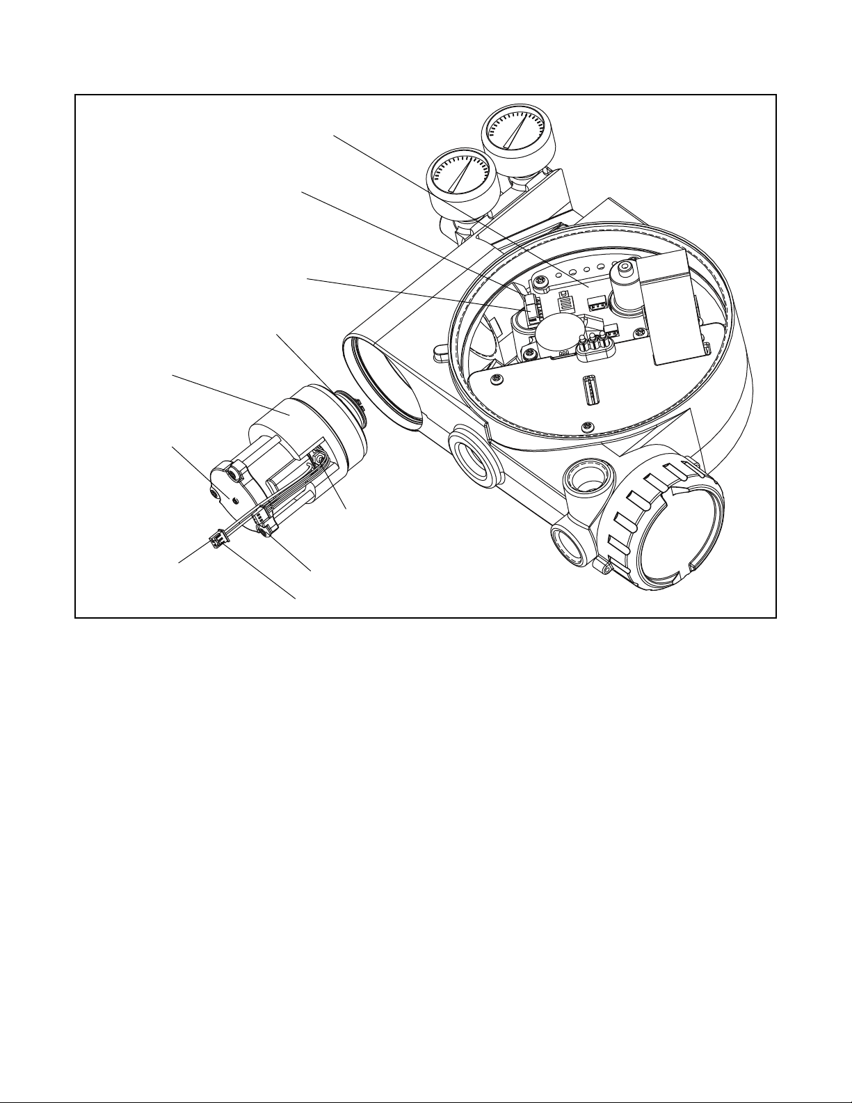
.
O
Digital Position
Algorithm
LED
Display
Air-to-open
Configuration
Flame Arrestors
Spool Valve
Exhaust
OUTPUT 1
Collector Board
Pressure Sensor
Air Supply
OUTPUT 2
Exhaust
Flame
Arrestor
Stem Position Sensor
Hall Effect Sensor
Electro magnetic Coil
Nozzle
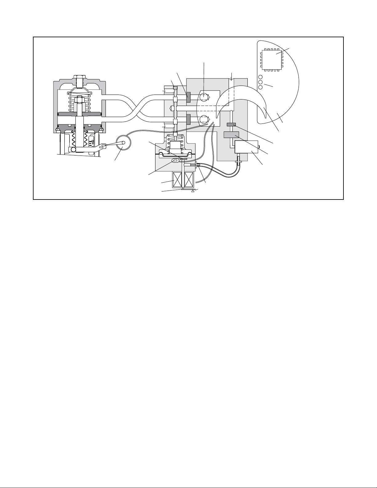
Figure 1: Logix 1200e Digital Positioner Schematic
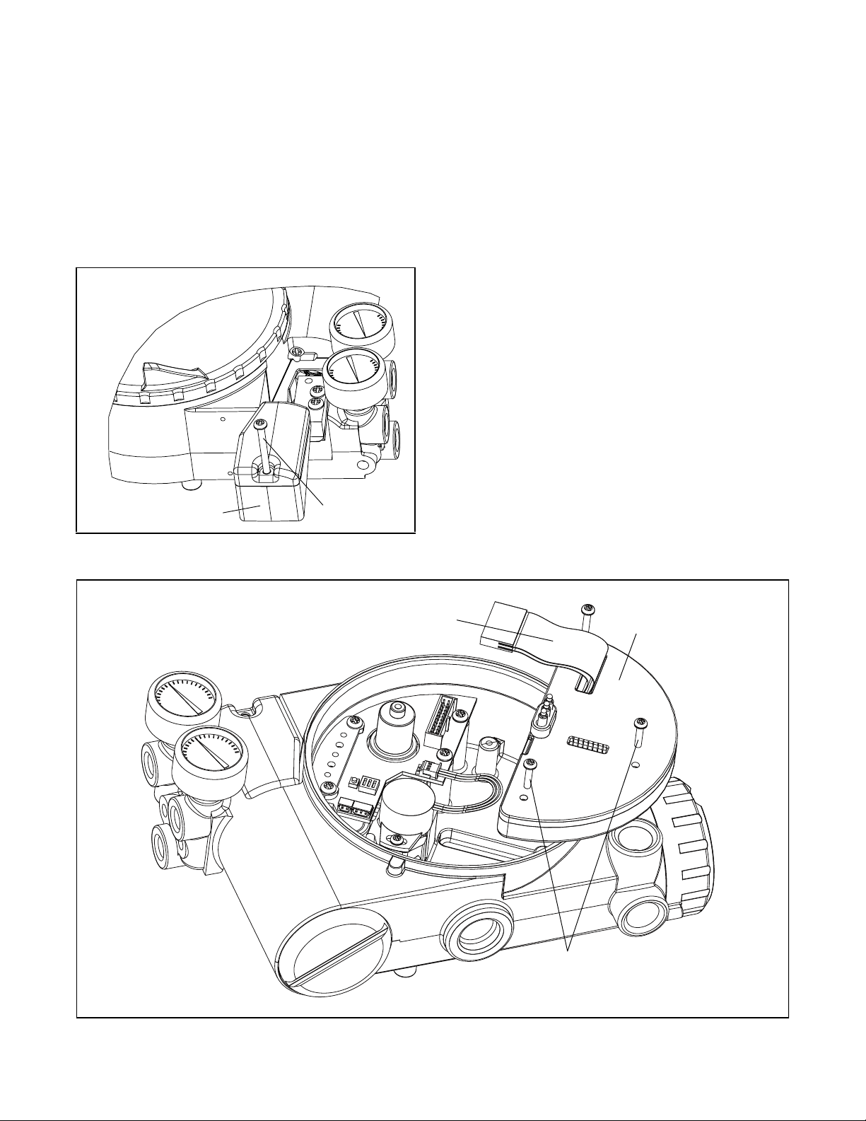
Positioner Operation
The Logix 1200e positioner is an electric feedback
instrument. Fig ure 1 shows a Logi x 1200e positioner
installed on a double-acting actuator for air-to-open
action. Positioning is based on a bal ance of two signals: one proportional to the command input signal
and the other proportional to the valve stem position.
The supply pressure for the positioner pressure modulator is tapped off the main supply. Next it passes
through an inter n al pres su re regul ato r that regul ates it
to approximately 22 psig. The air the n pass es throug h
an orifice that restricts the flow and air consumption.
The pressure modulator further controls the air to
6-10 psig, when operatin g current is applied, using a
spring-diaphragm fl apper that is attracted by an electromagnet to a nozzle. A temperature compensated
hall effect sensor mounted on a circuit board senses
the spool valve position. The hall effect sensor and circuitry create an inner feedback loop, which determines
how much current to send to the ele ctromagnet for a
desired spool valve position. The electro-magnet in
the feedback loop varies the nozzle-flapper spacing,
which regulates the o utput p ressure to 6-10 psig, proportional to the digital position algorithm.
When the command and stem position signals are
equal, the system will be in equilibrium and the valve
stem will be in the posi tion ca lled for by the command
signal. If these opposing signals are not equal, the
spool valve will move up (or down) and, by means of
Main PCB Tray
Ribbon Cable
Flame Arrestor
Filter
Regulator
Orifice
Flapper
the pressure modulato r, change output pressures an d
flow rate. This will cause the actuator pi ston to move
until the signal of the position sensor equalizes with
the command signal.
Detailed Sequence of Positioner Operations
The detailed sequen ce of positioner operations is as
follows: An increase in the command signal causes
the modulator pressur e to incr ease, push ing the spool
assembly upward from its equilibrium position. This
opens the spool valve ports, su pplying air to Output 1
and exhausting air from Output 2. This causes the
actuator piston to move upward.
The upward motion of the piston is transmitted back to
the positioner through the s tem pos ition feedback linkage, changing propor tionally to the valve stem position. The piston continues to stroke upward until the
stem position signal of the sensor increases sufficiently to counter th e signal being sent to the control
algorithm. At this po int, the spool is at its equilibriu m
position as the pres sures in the cylinde r stabilize and
the air flow to the actu ator decreases. The positio ner
will then make small null adjustments to fine-tune the
desired position and compensate for changes in
dynamic loading.
A decrease in the command signal reverses the
described actions, causing a proportional downward
movement of the actuator piston and stem.
44-4 Flowserve Corporation, Valtek Control Products, Tel. USA 801 489 8611
Page 5
Logix 1000 Series Positioner Vented-d esign Conversion
A standard Logix 1000 series positioner is vented
directly to the atmosp here. When supply air is su bstituted with sweet natural gas, the following changes
and considerations must be met . Piping must be u sed
to route the exhausted natural g as to a safe environment. This piping system may cause som e positioner
back pressure in the main chamber (from mod ulator)
and spool chambers (fro m actuator). This increase i n
pressure is due to restrictions caused by piping losses
from the pipe and fittings
Maximum Allowable Housing
Back Pressure
1 psi (0.07 bar)
1
4
-inch NPT x 4-inch
Swagelok Tube Fitting
1
4
-inch FNTP x 8-inch
MNPT Reducer
1
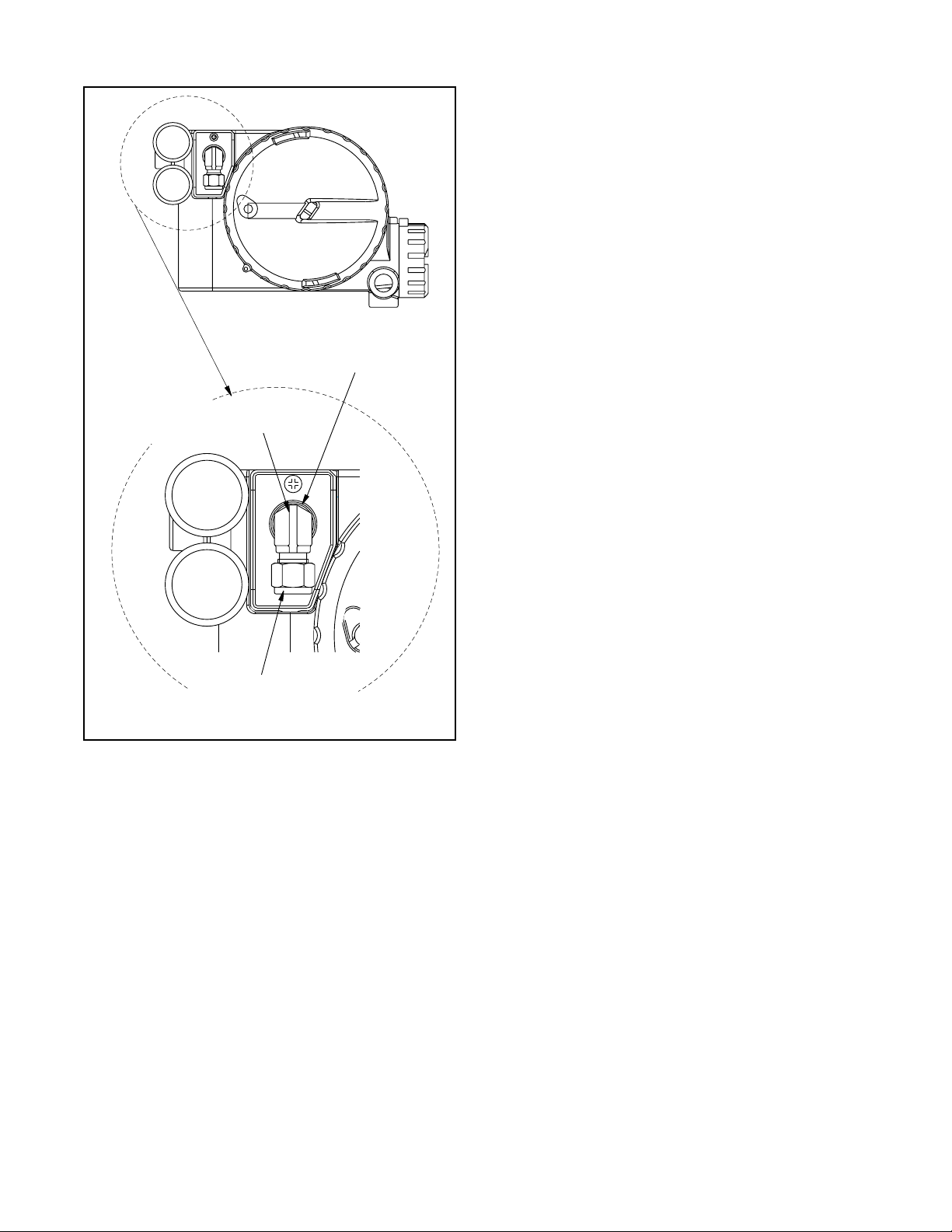
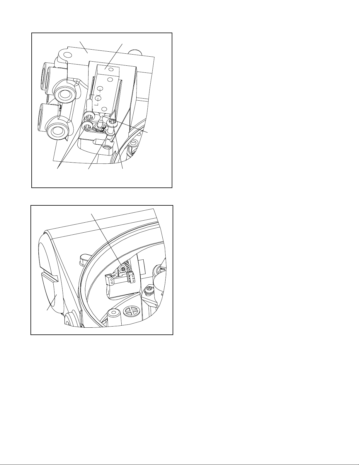
Figure 3: Main Housing Vent
1
Two chambers must be vented on the Logix 1000
series positio ners: the main hou sing cham ber and the
spool valve chamber (Figures 1 and 2). The main
chamber vent is located on the backside of the positioner (see Figur e 1). Ther e is a small, silver-colored
cover (item 24, SKU 10097867), protecting the vent
which must be removed and can be discarded.
1
A fitting may now be threaded into th e
/8-inch NPT
hole and tubing/piping attached.
NOTE: On rotary prod ucts, the mounting bracket covers the main housing vent. An adequate size access
hole must be drilled in the bracket at the time of
assembly to allow access to the main housing vent.
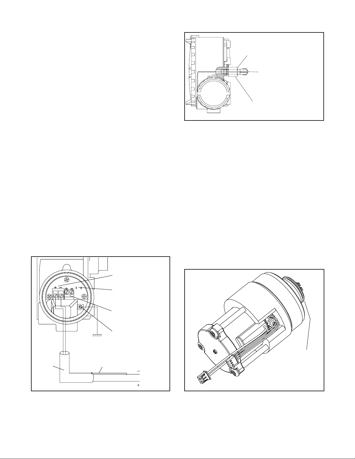
Field Terminations
HAR T Connection
Terminals
The maximum all owa ble back pressure fr om the collection device on the main housing vent is 1.0 psi
3
(0.07 bar). Vent flow rate is 244 standard in
/min.
WARNING: The back pressure must never rise
above 2.0 psi (0.14 bar).
If this occurs the weather seal boot (SKU 130884),
found on the early versions of the Logix 1000 positioner, identified by the diagonal window in the main
cover, must be checked for proper sealing, as overpressure will move the seal out of place. (See
Figure 4). Damage will not oc cur to the s eal, only s eal
alignment will be affected. A typic al sign of boot lea kage is a dramatic deterioration of positioner performance. To correct the seal, remove the driver module
and simply re-ali gn back into its groove. If back pressure of 3.5 psi (0.24 bar) is reached, total valve control
will be lost.
4-20 mA Feedback
Terminals (optional)
Housing EARTH
Terminal
Seal Boot
Shielded
Connect Shield at Source Ground
Cable
4-20 mA Current Source
Figure 2: Field Termination
Flowserve Corporation, Valtek Control Products, Tel. USA 801 489 8611 44-5
Figure 4: Seal on Modulator
Page 6
3
/8-inch NPT x 3/8-inch
Swagelok Tube Fitting
Maximum Allowable
spool Back Pressure
8 psi (0.55 bar)
will cause problems with overshoot but permanent
damage will not occur until pressures exceed 20 psi
(1.4 bar).
Tubing Positioner to Actuator
Proper tubing orientation is critical for the posit ion er to
function correctly and have the proper failure mode.
Refer to Figure 1 and note that for air-to-open valves,
the Output 1 port of the positioner mani fold is tubed to
the bottom side of the ac tuator. The Output 2 port of
the positioner manifold is tubed to the top side of the
actuator. For air-to-close valves the above configuration is reversed.
For single-acting actuators Output 1 port is always
tubed to the actuator regardless of air action. Output 2
port must be plugged.
WARNING: This product has electrical conduit
connections in either thread sizes 0.5- inch NPT or
M20 which appear identical but are not interchangeable. Forcing dissimilar threads together
will damage equipment, cause personal injury and
void hazardous location cer tifications. Conduit fittings must match equipment housing threads
before installation. If threads do not match, obtain
suitable adapters or contact a Flowserve office.
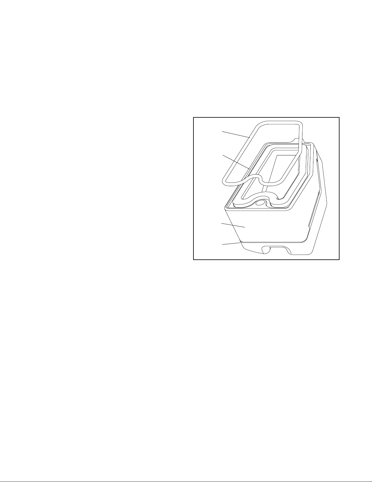
Customer Connection
3
/8-inch Tubing
Figure 5: Spool Cover Vent
The spool valve chamber has two parts: the spool
valve cover, (item 9, SKU 130811) and spool valve
shroud (item 10, SKU 1308 25). The spo ol valve cover
is replaced by SKU 101346 49 for early versions of the
Logix 1000 posi tioner or SKU 1016 0335 for later versions (identified by the 1200e or the round win dow in
the main cover). This new cover has a
hole where tubing/pipin g must be attach ed. The sp ool
valve shroud is discarded and not replaced with a nything. The maximum allowable back pressure while
stroking the valve is 8 psi (0.55 bar). Hi ghe r p re ssur es
3
/8-inch NPT
Wiring and Grounding Guidelines
Input Cable Shielding (Figure 2)
The input loop current signal to the Logix 1200e digital
positioner should be in shielded cable. Shields must
be tied to a ground at only one end of the cable to provide a place for environmental electrical noise to be
removed from the cable. In general, shield wire should
be connected at the source.
Grounding Screw
The green grounding scr ew, locate d inside the term ination cap, should be used to provide the unit with an
adequate and reliable earth ground reference. This
ground should be tied to the same ground as the electrical conduit. Additionally , the electrical conduit should
be earth grounded at both ends of its run.
The green grounding screw must not be used to
terminate signal shield wires
.
44-6 Flowserve Corporation, Valtek Control Products, Tel. USA 801 489 8611
Page 7
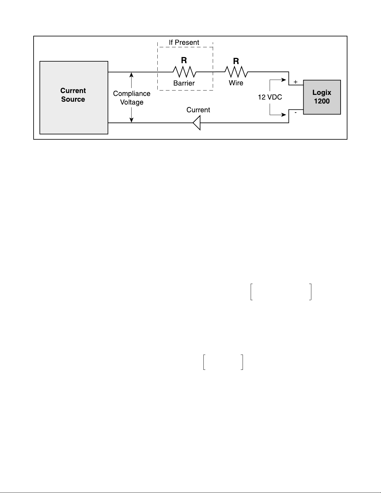
Figure 6: Co mpliance Voltage
Compliance Voltage (Figure 6)
Output compliance voltage refers to the voltage limit
that can be provided by the current source. A current
loop system consists of the current source, wiring
resistance, barrier resistance (if present), and the
Logix 1200e posi tioner impedance. The Logix 1200 e
digital positioner r equires that the current lo op system
allows for a 12.0 VDC drop across the positioner at
maximum loop current. The 12.0 VDC drop across the
Logix 1200e positi oner terminals is ge nerated by the
positioner from the 4-20 mA loop current input.
CAUTION: Never connect a voltage source directly
across the positioner terminals. This co uld cause
permanent circuit board damage.
Determine if the loop will support the Logix 1200e digital positioner by performing the following calculation.
Voltage = Compliance Voltage (
- Current
MAX
*(R
barrier+Rwire
)
@
Current
MAX
)
The calculated voltage must be greater than 12 VDC
in order to support the Logix 1200e digital positioner.
Example: DCS Compliance Voltage = 19 V
Cable Requirements
The Logix 1200e digital positioner utilizes the HART
Communication protocol. This communication signal
is superimposed on the DC 4-20 mA current signal.
The two frequencies used by the HART protocol are
1200e Hz and 220 0 Hz. In order to prevent distortio n
of the HART communication, cable capacitance and
cable length restrictions must be calculated. The cable
length must be limited if the capacitance is too high.
Selecting a cable with lower capacitance/foot rating
will allow longer cable runs. In addition to the cable
capacitance, the network resistance also affects the
allowable cable length.
In order to calculate the maximum network capacitance, use the following formu la.
C
network
Example: R
= 50
R
wire
Ω
µF()
barrier
C
cable
≤
--------------------------------------------------------------
R
()
barrierRwire
= 300
Ω
22ρF
--------------
65
++
foot
390
0.000022µF
--------------------------------==
foot
0.0032
–
R
= 300
barrier
= 25
R
wire
Ω
CURRENT
Ω
= 20 mA
MAX
65
---------------------------------------
30050390
++
Max Cable Length
0.0032–0.08µFC
==
C
-----------------------------------=
network
C
network
network
µF()
Max
µF()
()
Voltage = 19 V - 0.020 A*(300 Ω + 25 Ω)
= 12.5 V
Max Cable Length
0.08µF
-----------------------------------------------=
0.000022µF foot
⁄
The voltage 12.5 V is greater than the required 12.0 V;
therefore, this system will support the Logix 1200e digital positioner. The Logix 1200e positioner has an
input resistance equivalent to 625 Ω at a 20 mA input
current.
Flowserve Corporation, Valtek Control Products, Tel. USA 801 489 8611 44-7
To control cable resistance, No. 24 AWG cable should
be used for runs less than 5000 feet. For cable runs
longer than 5000 feet, No. 20 AWG cable should be
used.
Page 8
Driver Module Assembly
Minimum Pressure
Set Screw (factory
calibrated)
Collector Board
Pressure
Modulator
Connection
Hall Sensor
Connection
O-ring
Install orifice before driver
module is in housing
Position wires to
the rear of Modulator
Hall Sensor Connector
Pressure Modulator Connector
Figure 7: Driver Module Assembly
Driver Module Assembly
The driver module assembly moves the spool valve by
means of differential pressures on its diaphragm. Air is
routed to the module from the regulator through a
hose that connects to the assembly through a hose
barb with an integral orifice. Wires from the module
connect the hall effect sensor an d the pr es su re modulator coil to the collector board.
Driver Module Assembly Replacement
To replace the driver module assembly, refer to
Figure 7, 8, 9, 11, 20 and procee d as outlined below.
The following tools are required:
Flat plate/bar about
Phillips screwdriver
1. Make sure valve is bypassed or in a safe condition.
2. Disconnect the power and air supply to the unit.
3. Remove the driver module cover (Figure 9), using
flat bar/plate in slot.
1
/8-inch thick
4. Remove the spool valve cover by removing the
screw and sliding the cover assembly backwards
until the tab is clear of the slot. Removing the sheet
metal cap, hydrophobic filter, or O-ring from this
assembly is not necessary (Figure 11).
5. Being careful not to l ose the nylon washer, remove
the Phillips-head screw that attaches the driver
module to the main housing (Figure 8).
6. Remove the spool valve block by removing the two
Phillips-head scr ews and carefully slidin g the block
off the spool (Figure 8).
CAUTION: The spool (extending from the driver
assembly) is easily damaged. Use extreme caution when handling the spool and spool valve
block.
7. Carefully remove spool by slid ing end of spool ou t
of connecting clip. Excessive force may bend spool.
8. Remove main cover.
44-8 Flowserve Corporation, Valtek Control Products, Tel. USA 801 489 8611
Page 9
Spool Valve
Screws
Spool Valve BlockHousing
Ny lon
Gaskets
Driver to
Housing Screws
Figure 8: Spool and Block
Spool
opening. This will al low the dri ver module to threa d
out without tangling or cutting the wires.
12.Grasp the driver module pressure modulator cap to
rotate the entire driver module. Turn it counter
clockwise to remove. After it is threaded ou t, carefully retract the driver module from the housing.
13.Take new driver module, and verify that the O-ring
is in place. Lay the wires back and along modulator
as shown in Figure 7, and hold in place by hand.
14.Gently direct the driver module into the housing
bore. Turn the dr iver module clockwise to thread it
into the housing. Continue rotating the module until
it bottoms out.
15.Once the threads are fully engaged, rotate the
driver module counter clockwise until the flat on the
driver module and the flat on the housing are
aligned. This wi ll align the sc rew holes for the next
step.
16.Verify that nylon gasket is in the counter bore in the
driver module retaining screw hole as shown in
Figure 8.
Orifice
Driver
Modul e
Cover
Figure 9: Driver Module Orifice
9. Remove the tubing from the orifice in the driver
module assembly (Figure 9) .
10.Remove the two wiring connections that link the
driver module assembly to the collector board.
17.Insert a driver-to-housing screw into the driver
housing through the counter-bored hole in positioner main housing. T ighten with a phillips screwdriver.
18.Feed the driver module wires in to the main chamber of the housing , an d c onn ec t th em to th e c olle ctor board.
19.Verify that the three O-rings are in the counterbores on the machined platform where the spool
valve block is to be placed (Figure 20).
20.Carefully slide the spool in to the connec ting clip of
the driver module assembly.
21.Carefully slide the block over the spool, using the
machined surface of the housing base as a register
(Figure 8). Slide the block toward the driver module
until the two retaining holes line up with the
threaded holes in the base.
22.Install two spo ol-valve screws and ti ghten se curely
with a Phillips screwdriver.
23.Slide the spool valve cover assembly over the spool
valve until the tang engages into housing slot.
Install spool valve cover screw and tighten securely .
11.Feed the wires back through the housing so they
extend backward, out toward the driver module
Flowserve Corporation, Valtek Control Products, Tel. USA 801 489 8611 44-9
24.Thread main cover and driver module cover into
the main housing.
Page 10
Spool Valve
To replace the spoo l valve, refe r to Figure 8, 10 & 1 1
and proceed as outlined below.
1. Make sure valve is bypassed or in a safe condition.
2. Disconnect the power and air supply to the unit.
3. Remove the spool valve cover by removing the
screw and sliding the cover assembly backwards
until the tab is clear of the slot. It is not neces sary
to remove the sheet metal cap, hydrophobic filter,
or O-ring from this assembly (Figure 11).
5. Grasp the bottom of the regulator and unscrew it
from the interface plate.
6. Ver ify that the O-ri ngs are in place on the base of
the new regulator and thread it into the hole in
interface plate.
7. Install four screws to fasten the collector boar d into
the housing. Replace the four wire connections.
8. Attach the flexible tubing to the orifice.
9. Re-install all covers.
4. Remove the spool valve block by removing the two
phillips-head s crews and car efully sl iding the block
off the spool (Figure 8).
CAUTION: Spool (extending from driver assembly) is easily damaged. Use extreme caution
when handling spool and spool valve block.
5. Carefully remove spool by sliding en d of spool out
of connecting clip. Excessive force may bend the
spool.
6. Verify that the three O-rings are in the counterbores on the machined platform where the new
spool valve block is to be placed (Figure 20).
7. Careful slide the spool into the connecting clip of
the driver module assembly.
8. Carefully slide the block over the spool, using the
machined surface of the housing base as a register
(Figure 8). Slide the block toward the driver module
until the two retaining holes line up with the
threaded holes in the base.
9. Install two spool-valve screws and tighten securely
with a phillips screwdriver.
10.Slide the spool valve cover assembly over the spool
valve until the tang engages into housing slot.
Install the spool valve cover screw and tighten
securely.
O-ring
Hyd rophobic
Filter
Spool Valve Cover
Spool
Valve Shroud
Figure 10: Spool Valve Cover Assembly
Spool Valve Cover
The spool valve cover incorporates a coalescing filter
element in a t wo-piece cover. This protects t he spool
valve chamber from moisture and provides a low back
pressure vent for exhaust air from the spool valve.
Replacing Filter in Spool Valve Cover
1. Make sure valve is bypassed or in a safe condition.
Regulator
The regulator reduces the pressure of the incoming
supply air to a level that the driver module can use.
Replacing Regulator
2. Disconnect the power and air supply to the unit.
3. Remove the spool cover by removing the screw
and sliding the cover assembly backwards until the
tab is clear of the slot. The sheet metal cover may
be removed and cleaned with a brush or by blowing
out with compressed air (Figure 11).
1. Make sure valve is bypassed or in a safe condition.
4. Remove the O-ring from around hydrophob ic filter
2. Disconnect the power and air supply to the unit.
3. Remove the main cover.
4. Remove the four wire connections from the c ollector board. Next remove the four screws that fasten
the collector board to the housing.
44-10 Flowserve Corporation, Valtek Control Products, Tel. USA 801 489 8611
element and set aside (Figure 10).
5. Remove the molded filter element by pulling
straight out of chamber cover vent piece.
6. Install O-ring into base of chamber cover vent piece
as shown in Figure 10.
Page 11
7. Place new molded filter element into the chamb er
cover vent piece. This element provides part of the
track to secure the O-ring installed in the last step.
8. Place spool valve shroud onto spool valve cover.
9. Place the spool valve cover assembly in place by
setting it on the ramp and sliding it until the tab seats
in the slot (Figure 11) and secure with No. 8-32
screw.
Spool Valve Cover
Screw
Main PCB Assembly
The main PCB assembly contains the circuit board
and processor that perform control functions of the
positioner. The board is encapsulat ed in a tray with a
protective silicon coating. This module can be easily
replaced if necess ar y. None of the compo nents insid e
the tray are serviceable. This module is to be replaced
as a unit.
Replacing Main PCB Assembly (Figure 12)
1. Make sure valve is bypassed or in a safe condition.
2. Disconnect the power and air supply to the unit.
3. Remove the main cover and disconnect the ribbon
cable from the collector board.
CAUTION: To avoid damaging any components,
exercise caution by gently raising the locking
tab to release the ribbon cable.
4. Remove the PCB assembly by removing the three
No. 6-32 screws and lifting the tray out of housing.
5. Place the new PCB assembly on th e bo ss es i nsid e
the positioner housing.
6. Insert three No. 6-32 screws through the tray into
the threaded bosses and tighten evenly, using a
phillips screwdriver. Do not overtighten.
Figure 11: Spool Valve Cover Assembly
Ribbon Cable
7. Reconnect the ribbon ca ble to the collect or board
Main PCB
Assembly
Screws (3)
Figure 12: Main PCB Assembly
Flowserve Corporation, Valtek Control Products, Tel. USA 801 489 8611 44-11
Page 12

Collector Board
The collector board assem bly provides a central routing for all electronic connec tio ns in the pos it ion er, linking the pressure modulato r coil, hall effect sensor and
field in put s to the mai n el ect ro nics. The collector b oar d
assembly also provides for mount ing of the pressure
sensors used in the advanced model.
Removing Collector Board (Figure 20)
1. Make sure valve is bypassed or in a safe condition.
2. Disconnect the power and air supply to the unit.
3. Remov e th e main co v er an d discon nect t he wi ring to
the collector board. Each cable has its own unique
connector to prevent mistakes in reconnecting.
4. Remove the four No. 8-32 screws holding the
collector board to the housing.
5. Remove the collector board.
NOTE: Th e two screws through the stiffener plate
are longer.
5. Tighten all four screws.
6. Connect the main ribbon from the electronics tray.
7. Reconnect wiring to the collector board.
Field Terminations
The customer interface board provides a connection
point inside the explosion proo f housing for all hookups to positioner. While the board is not li kely to experience a failure, it can easily be replaced.
Replacing Customer Interface Board
(Figure 2 & 20)
1. Make sure valve is bypassed or in a safe condition.
2. Disconnect the power and air supply to the unit.
3. Remove the main cover and disconnect the customer interface cable from collector board.
Replacing Collector Board
NOTE: A Logix 120X (standard model) cannot be
upgraded to a Logix 1210e (advanced model) by
changing out the co llect or bo ard. T he Logi x 12 0X an d
Logix 1210e use different positioner housings.
1. Advanced collector board only – Verify that pressures sensors are in place on back of collector
board, and that the two O-rings are in place.
2. Set collector board assembly in place.
3. Advanced collector boards req uire a stiffener plate
above the pressure sensors (Figure 2 0) .
4. Insert four No. 8-32 screws through the collector
board into the threaded holes of the housing.
4. Remove the customer interface cover and the three
No. 8-32 screws.
5. Remove customer interface board, c aref ully p ullin g
wiring through bore.
6. Verify that the O-ring is in pl ac e in the co unte r bore
in the positioner housing.
7. Feed wiring through p assageway into main chamber of housing.
8. Set the circuit board in pl ac e a nd s ecur e wit h th re e
No. 8-32 screws.
9. Connect customer interface cable to collector
board.
10.Replace covers.
44-12 Flowserve Corporation, Valtek Control Products, Tel. USA 801 489 8611
Page 13
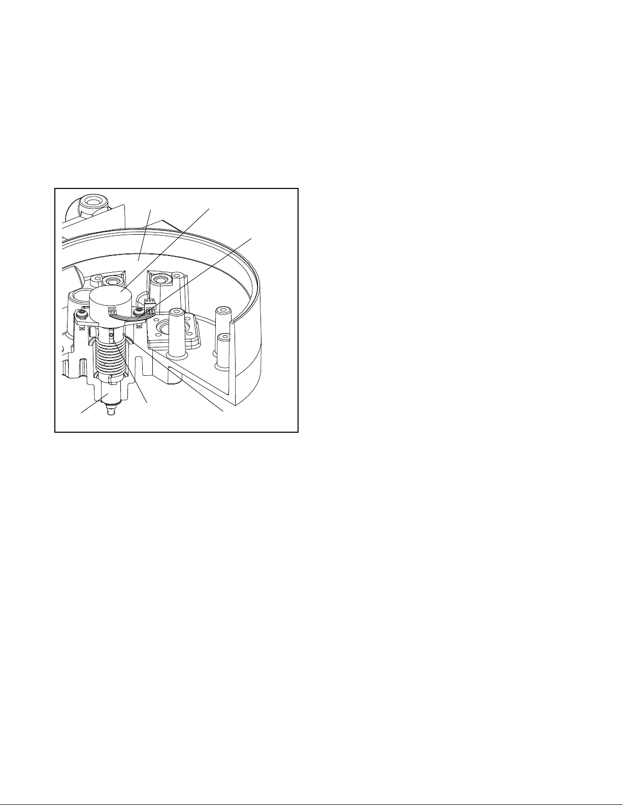
Stem Position Sensor
The position feedback assembly transmits valve position information to the proces so r. This is accom p li sh ed
by means of a rotar y position sensor that con nects to
the valve stem through a feedback linkage. To provid e
for accurate tracking of the pin in the slot, the follower
arm is biased against one side of the slot with a rotary
spring. This spring also automatically moves the position feedback assembly to its limit in the unlikely event
of failure of any component in the linkage.
8. Route wires alon g the position sensor and reconnect to collector board.
Mounting to Linear Mark One Valves
(See Figure 14)
The tools required for the following procedure are:
9
/16-inch open-end wrench
7
/16-inch box wrench
3
/8-inch open-end wrench
Bearing
Housing
Stem Position
Sensor Dot
Stem Position
Sensor
Sensor
Cable
Feedback Shaft
Figure 13: Stem Position Sensor
Orientation
Stem Position Sensor Replacement
(Figure 13, 20)
1. Make sure valve is bypassed or in a safe condition.
2. Disconnect the power and air supply to the unit.
1. Remove washer and nut first from follower pin
assembly. Insert pin into the appropriate hole in follower arm, based on stroke length. The stroke
lengths are stamped next to their corresponding
holes in the follower arms. Make sure the
unthreaded end of the pin is on the stamped side of
the arm. Reinsert lock washer and tighten nut to
complete follower arm assembly.
2. Slide the double-D slot i n the follower arm assembly over the flats on the position feedback shaft in
the back of the positioner. Make sure the arm is
pointing toward the customer interface side of the
positioner. Slide lock washer over the threads on
the shaft and tighten down the nut.
3. Align the bracket with the three outer mounting
holes on the positioner. Fasten with
1
/4-inch bolts.
4. Screw mounting bolt into the hole on the yoke
mounting pad nearest the cy linder. Stop when the
bolt is approximately
/
from being flush with
3
16-inch
mounting pad.
5. Slip the large end of teardrop shaped mounting
hole in the back of the position er/bracket assembly
over mounting bolt. Slide the small end of teardrop
under mounting bo lt and align the lower mountin g
holes.
3. Remove the main cover and disconnect rotary
6. Insert lower mounting bolt and tighten bolting.
position sensor wires from collector board.
7. Slide appropriate pin slot on the take-off arm, based
4. Remove the two screws from rotary position sensor
and remove the sensor from the housing.
5. Turn position sensor shaft until the dot on the slot is
oriented with the wires on the pot (Figure 13).
on stroke length, over follower arm pin. The appropriate stroke lengths are stamped by each pin slot.
8. Position the take-off arm mounting slot aga inst the
stem clamp mounting pad. Apply Loctite 222 to
take off arm bolting and insert through washers into
6. Insert the position sensor into the shaft with wires
stem clamp. Torque to 120 in-lbs.
pointing toward the main PCB assembly. Tur n the
position sensor clockwise until bolting slots align
with the housing screw holes an d the wires on th e
sensor protrude over the main PCB assembly tray.
7. Carefully center positi on sensor on the s haft bore,
insert and tighten the screws.
Flowserve Corporation, Valtek Control Products, Tel. USA 801 489 8611 44-13
Do not over tigh ten.
9. Center the take-off ar m on the rolling sleeve of the
follower pin.
10.Align take-off ar m wit h top pl ane of th e s tem cl am p
and tighten bolting.
Page 14
Logix 1200 Positioner
Locknut
Washer
Follower
Arm
Take-off Arm
Nut
Lock Washer
Nut
Follower Pin
Bracket Bolts
Bracket
Positioner
Bolts
Nut
Stem Clamp
Bolts
Figure 14: Linear Mark One Control Valve Mounting
Standard Rotary Mounting Procedure
(See Figure 15)
The standard rotar y mounting applies to valve/actuator assemblies that do not have mounted volume tanks
or handwheels. The standard mounting uses a linkage
directly coupled to the valve shaft. This linkage has
been designed to allow for minimal misalignment
between the positioner and the actuator. The tools
required for the following procedure are:
5
/32 allen wrench
1
/2-inch end wrench
7
/16-inch end wrench
3
/8-inch socket with extension
3
/16 nutdriver
1. Fasten spline lever adapter to splined lever using
two No. 6 x 0.50-inch self tapping screws.
2. Slide take-off arm assembly onto spline lever
adapter shaft. Insert screw with star washer
through take-off arm and add second star washer
and nut. Tighten nut with socket so arm is lightly
snug on shaft but still able to rotate. This will be
tightened after linkage is correctly oriented.
Metal
Washers
3. Attach follower arm to positioner feedback shaft
using the star washer and No. 10-32 nut.
NOTE: Arm will poi nt up when feedback shaft is in
the free position.
1. Using four 0.25-20 x 0.50 L. bolts, fasten positioner
to universal bracket using appropr iate hole patter n
(stamped on bracket).
2. Using a
1
/2-inch end wrench and two 0.3125-18 x
0.50 L. bolts, attach bracket to actuator transfer
case pad. Leave these bolts slightly loose until final
adjustments are made.
3. Rotate take-off arm so the follower pin will slide into
its slot. Adjust bracket position not ing the engagement of the follower pin and the take-off ar m slot.
1
The pin should extend approximately
16-inch
/
past
take-off arm. When properly adjusted, securely
tighten the bracketing bolts.
Orienting the Take-off Arm for Final Lock Down
Tube positioner to valve in the following manner:
1. OUTPUT 1 por t of the m anifold to the bottom side
of the Actuator.
44-14 Flowserve Corporation, Valtek Control Products, Tel. USA 801 489 8611
Page 15

n
Logix 1200
Digital Positioner
Positioner Bolts 1/4-20 (4)*
5
Bracket Bolts
/16-18 (2) (not shown)
Take off Arm, Rotary
Lock Washer (2)
Bolt No.10-32
Nut No.10-32
Self Tapping Screws (2)
Spline Lever Adapter
Nut No.10-32
Lock Washer
Figure 15: Standard Rotary Mounting
2. OUTPUT 2 port of the manifold to the topside of
the actuator.
3.
With supply pressure off
the same direction the shaft would rotate upon a
loss of supply pressure. When the mechanical stop
of the follower arm (positioner) is reached, rotate
back approximately 15 degrees.
4. Hold the take-off arm in pl ace; tighten th e screw of
the take-off arm.
NOTE: The take-off arm should be snug enough to
hold the follower arm in place but allow movement
when pushed.
5. Connect regulated air suppl y to appropriate por t in
manifold.
, rotate the follower arm in
Follower Arm
* Located in appropriate
hole pattern as indicated o
bracket. (25, 50, 100/200)
8. Press the Quick-Cal button for 5 to 10 seconds or
until positioner b egins to move. The positioner will
now perform a stroke calibration.
9. If the calibration was successful the green LED will
blink and the valve will be in control mode. Continue with step 10. If calibration failed the A/D feedback values were exceeded and the arm must be
adjusted away from the positioners limits. Return to
step 3 and back off approximately 10 degrees.
NOTE: Remember to remove the air supply before
re-adjusting take-off-arm.
10.Tighten the nut on the take-off arm. The socket
head screw of the take-off arm must be tight, about
40 in-lbs.
NOTE: If the take-off arm slips, the positioner must
be re-calibrated.
6. Remove main cover and locate DIP switches and
Quick-Cal button
7. Refer to sticker on main board tray and set DIP
switches accordingly
Flowserve Corporation, Valtek Control Products, Tel. USA 801 489 8611 44-15
WARNING: Failur e to follow this proce dure will
result in positioner and/or linkage damage.
Check air-action and stroke carefully before
lockdown of take-off arm to spline lever
adapter.
Page 16

Tripper
Tripper Clamp
Tie Rod must be cut to desired length
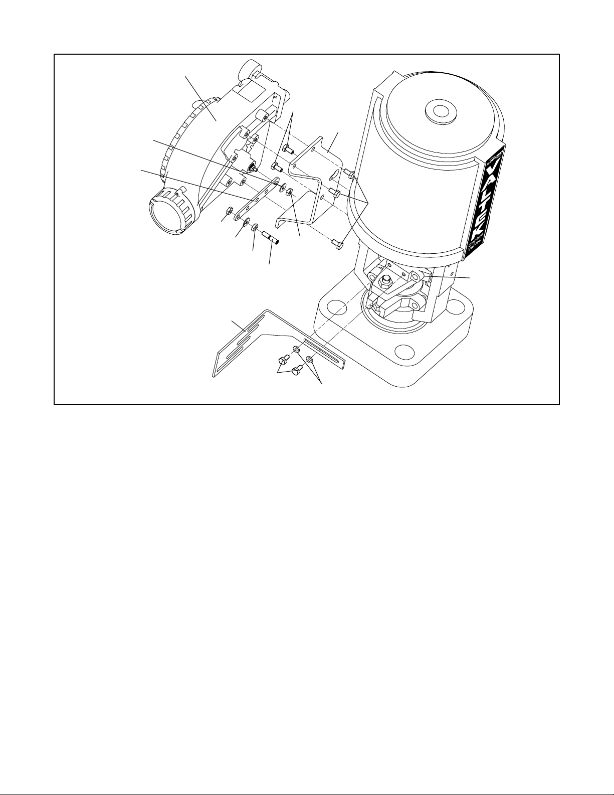
Figure 16: Optional Rotary Mounting
Bo lts (2)
Locknuts (2)
*Tie Rod
Nut No. 10-32
Lock Washer
5
Bracket Bo lts
/16-18 (2)
Ball oint Ends
Follower Arm
Rotate Positioner 90°
Mounting Bo lts
1
/4-20 (4)
Optional Rotary Mounting Procedure
The optional rotar y mounti ng applie s to valve/actuator
assemblies that are equipped with mounted volume
tanks or handwheels. The optional mounting uses a
four-bar linkage coupled to the valve shaft. The following tools are required:
3
8-inch
/
box wrench
7
16-inch
/
1
/
2-inch
box wrench
box wrench
90 degrees from normal so gauges are facing
upward.
3. Attach follower arm to positioner feedback shaft,
using the star washer and No. 10-32 nut.
4. Attach tripper and tr ipper clamp to shaft, u sing two
-
0.25
20 L. bolts and two 0.25-20 locknuts. Leave
tripper loose on shaft until final adjustment.
5. Thread ball joint link age end to tripper and tighten
(Thread locking compoun d such as Loctite is rec-
1
1. Using a
x 0.50 L. bolts, attach bracket to actuator t ransfer
case pads. Leave bracket loose to allow for
adjustment.
2. Using four 0.25
box wrench, fasten positioner to universal b racket,
2-inch
/
box end wrench and two 0.3125-18
-
20 x 0.50 L. bolts and a 7/
16-inch
ommended to prevent back threading). Adjust
length of tie rod so follower arm and tripper rotate
parallel to each other ( the rod must be cut to the
desired length). Connect other ball joint end to follower arm using a star washer and a No. 10-32 nut.
6. Tighten bracket and tripper bolting.
using the four-hole pattern that locates the positioner the farth est from the valve. Rotate position er
44-16 Flowserve Corporation, Valtek Control Products, Tel. USA 801 489 8611
7. Check for pr op er o per a tio n, no te d irect ion of ro tat io n.
Page 17

WARNING: If rotating in wrong direction, serious damage will occur to the positioner and/or
linkage. Check air action and stroke direction
carefully.
LED Indicators
The Logix 1200e has three LED indicators that are visible through a window in the main cover . Only one LED
will blink at any given time. Each LED ha s a different
color to convey basic information abou t the positioner
status. Green indicates th at th e positioner is operatin g
normally. Yellow indicates that a ‘customer defined
limit’ or ‘alert’ has been reached. Red indicates that an
error condition exists. The HART hand held com municator, ValTalk or SoftTools P C software must be u sed
to determine the specific reason for a yellow or red
LED status.
During stroke and actuator calibration, no LED will
blink. After calibration is complete, the green LED indicates that the calibration was completed successfully.
If the yellow or red LED blinks after a calibration process, a warning or err or was detected and the HART
communication to the device must be used to identify
the specific calibration error.
NOTE: If the LED indicator changes from green to yellow after a calibration process, the user may have set
a warning limit (position alert, cycle counter alert,
etc.). Use HART communications to monitor status.
Stroke Calibration using the Quick-Cal Button
For cases when the HART hand held communicator,
Va lTalk or SoftTools PC software is no t avail able, the
Logix 1200e has a Quick-Cal feature that performs a
stroke calibration and allows basic operation of the
positioner. The Quick-Cal routine applies full supply
pressure to the uppe r and lower mechanical limits t o
determine the valve stroke. Valve systems without
mechanical stops must use the ValTalk or SoftTools
software to manually calibrate the valve.
WA RNING: The calibration routines are only to be
used on systems which have mechanical stops.
The calibration routines apply full supply pressure
to determine stroke length and may cause damage
to the valve, actuator or positioner.
NOTE: The Quick-Cal operation retains all previously
configured information except for the three DIP switch
settings and stroke parameters. The settings of
ATO/ATC, Linear/Rotary, Linear/Custom and stroke
parameters are overridden and res t to the DIP switch
settings when the Quick-Cal button is used. If the
device is being installed for the first time, factory
default parameters are used.
The Quick-Cal button and DIP switch settings are
located on the collec tor board inside the main housing
chamber as shown in Figure 17.
Quick-Cal DIP Switch
Quick-Cal Button
Figure 17: Quick-Cal Button
WARNING: Accessing this function requires
removal of the main cover. The user must take all
precautions if this operation is performed in e xplosion-proof areas.
Make the approp r i ate configurat io n s e tt ings, using the
DIP switches on the collector board.
air-to-open or air-to-close (this is determined by the
mechanical tubing of the actuator). The
LIN_VALV/ROT_VALV
linear or rotary feedback linkage. The LIN_VALV
switch enables the feedback potentiometer to utilize
the entire resolution through a maximum of 60
degrees rotation (45 degrees is typical). The
ROT_VALV switch increases the rotation of the potentiometer up to 105 degrees (90 degrees is typical).
Thus a long stroke sliding stem valve may require this
dip switch to be set on ROT_VALV if the stroke rotates
the feedback potentiometer more than 60 degrees.
The
LIN/CUSTOM
custom control characterization. If
selected, the positioner activates custom characterization. If the device is being installed for the first time,
the default custo m characterization i s equal percent.
However, if a custom curve has been previously
loaded, the previous curve will be used. The DIP
switch settings ar e only read afte r the Quick-Cal button is pressed for 5 seconds; otherwise, the settings
do not have any effect. The DIP switch settings will
override any previous configuration done using HART
communication s. Press th e Qui c k-Cal b u tton f or fiv e to
ten seconds. I f the butto n is re leased before five seconds have elapsed, no action will be taken. After
approximately five seconds, the positioner will begin a
ATO/ATC
button allows the user to select
option allows selection of linear or
selects
Custom
is
Flowserve Corporation, Valtek Control Products, Tel. USA 801 489 8611 44-17
Page 18

stroke calibration. Release the Quick-Cal button once
calibration has star ted. The positioner will automatically stroke the valve. The stroke sequence will be to
the extremes (open to close), to the mid stroke, then
to the signal position. No LED will blink during this
process.
NOTE: If Quick-Cal is interrupted during calibration
the mode of the positioner may stay in digital, requiring
HART communications to place it back into analog.
If calibration was successful, upon completion the
green LED will blink and the valve will be in control
mode. If the yellow LED blinks immediately after a
stroke calibration, this usually indic ates that the valve
did not stroke. Check the air supply and cable connections. If a calibration e rror occurred, the red LED will
blink. The cause of a red LED is generally a stem position linkage/feedback sensor alignment problem. For
linear linkage, the active electrical feedback angle is
65 degrees. For rotary linkage, the active electrical
feedback angle is 95 degrees. The red LED indicates
that the mechanical travel is not centered within the
electrical sensor travel. If a red LED is blinking after a
stroke calibration, loosen the feedback sensor mounting screws as shown in F ig ure 18. Turn the stem position sensor slowly while watching the LED indicators.
Try small movements, both clockwise and counterclockwise. If the yellow LED begins to blink, the feedback sensor has been correctly moved into range.
Tighten the feedback sensor mounting screws and
repeat the Quick-Cal procedure. If the LED remains
red even after moving the full length of the sensor slot,
verify the following items are correctly set:
LIN_VALV/ROT_VALV
DIP switch setting, stem cl amp
and take-off arm height.
NOTE: If the stroke calibration stops in the closed
position, the error occurred when the position
sensor/linkage was at closed position. If the stroke
calibration stops in the open position, the error
occurred when position sensor/linkage was at the
open position. No ca libration parameters are saved if
an error occurs. If the power to the positioner is
removed, the unit will power-up with the previous
configuration parameters. A successfu l calibration wi ll
save parameters.
If the valve does not stroke after pressing the QuickCal button, this may be an indication that the inter nal
regulator pressure and/o r the driver module minimum
pressure is low. Refer to the following instruct ions to
check and set the internal regulator and minimum
pressure settings.
NOTE: Ensure that all linkages are tight an d correctly
mounted before attempting to calibrate. Loose or
incorrectly moun ted linkage will cause c alibration failure and difficulty in troubleshooting.
Rotate Stem Position Sensor slol
Stem Position
Sensor Mounting Screws (2)
Figure 18: Stem Position Sensor
Adjustment
Checking or Setting Internal Regulator Pressure
The tools and equipm ent used in the next procedure
are from indicated vendors.
1. Make sure valve is bypassed or in a safe condition.
2. Disconnect the air supply from the positioner.
3. Remove the main cover and the
tubing from the driver module orifice.
4. Obtain a barbed tee (Pneumadyne part No. SBF16T or equivalent) and two p ieces o f
ble tubing, a few inches in length each.
5. Connect the
1
/16 inch flexible tubing, found in the
positioner, to the barbed tee. Using one of the new
flexible tubing pieces connect the barb ed te e to th e
orifice. Connect the remaining tee port to a 0 to 30
psi pressure gauge.
6. Reconnect the air supply to the positioner and read
the internal regulator pressure on the 0 to 30
gauge. The inter nal pressur e sho uld b e set to 21. 5
±0.5 psi. If adjustment in needed, scrape off the silicon compound covering the screw. Then adjust the
regulator pressure by turning the setscrew on top
of the regulator with a small screwdriver.
7. Once the regulator pressure is set, remove the air
supply to the positioner, remove the barbed tee,
and reconnect the posi tioner 's flexible tubing to the
orifice.
8. Reconnect air supply to positioner.
1
16
/
inch flexible
1
16
/
inch flexi-
44-18 Flowserve Corporation, Valtek Control Products, Tel. USA 801 489 8611
Page 19

No. 10-32 Extension
(Clippard Part No. 15010)
5. Remove the No. 10-32 x 0.016 orifice and gasket
1
(Figure 9) from the driver module using a
2-inch
/
nut driver. Take care to not misplace the gasket.
Minimum Pressure
Test Port
1
No.10-32 x
/16
Barb
No.10-32 x .016
Orifice
Pressure from Internal
Regulator to be tubed to
No.10-32 x Swivel
TEE (Pneumadyne
Part No. SFL-10)
this orifice
Figure 19: Driver Module Minimum
Pressure Check
Checking or Setting the Driver Module Minimum Pressure
Refer to Figure 19, proceed as follows:
1. Make sure valve is bypassed or in a safe condition.
2. Disconnect power from the positioner.
3. Remove the main cover and remove the
ble tubing from the orifice.
4. Obtain a No. 10-32 x swivel elbow (Pneumadyne
part No. SFL-10 or equivalent) and a No. 10-32
extension (Clippard part No. 15010 or equivalent).
1
/16 flexi-
6. Screw in the 10-32 extension followed by the 10-32
x swivel elbow.
7. Direct the swivel elbow so the minimum pressure
test port is accessible.
8. Screw a No. 10-32 x
1
/16-inch barb fitting into the
test por t, and screw the No. 10-32 x 0.016 or ifice
into the end of the elbow as shown.
9. Connect the tubing from the inter nal regulator output port to the orifice.
10.Using some
1
/16-inch flexible tubing, connect a 0 to
30 psi gauge to the minimum pressure set port.
11.Once the gauge is connected, reapply the positioner air supply. The minimum pressure should
now be registering on the gauge and must be 3.8 to
4.2 psi. If the minimum pressure is not correct, take
9
a
/64 allen wrench and tur n the minimum pressure
set screw located at th e bottom of the dri ver module (Figure 7) until the pressure is in the range indicated. Cycle the posi tioner air sup ply several times
and recheck the minimum pressure and re-adjust, if
necessar y, to ensure that the pressure has settle d
within the range specified.
12.When the pressure is set, remove the air supply.
13.Remove the No. 10-32 x
1
/16 barb and orifice f rom
the swivel elbow and then remove swivel elbow and
extension.
14.Replace the orifice and gasket as shown in
Figure 9 and reco nnect t he
1
/16 inch flexible tubing
from the internal regulator output port to the orifice.
Reconnect the positioner air supply and power. The
positioner should now be ready to calibrate.
Flowserve Corporation, Valtek Control Products, Tel. USA 801 489 8611 44-19
Page 20

LOGIX 1200 Model Numbers
PROTOCOL
Selection Code
HART *2
DIAGNOSTICS
Selection Code
Standard *0
Advanced 1
MATERIAL
Selection Code
Aluminum, Valtek (White Paint) *0
Stainless Steel, Valtek (No Paint) 1
Aluminum, Automax (Black Paint) 2
Aluminum, Automax (Food Grade White Paint) 3
Aluminum, Accord (Black Paint) 4
Aluminum, Automax (Food Grade White Paint) 5
CERTIFICATIONS
Selection Code
Explosion proof EEx d IIB + H
Nonincendive Class I, Div. 2, (Factory Mutual), Class I, Div. 2 (CSA) 08
Explosion proof Class I, Div. 1, Groups B,C,D Intrinsically Safe Class I, 10
Div. 1, Groups A thru G (FM, CSA) FM Nonincendive. CSA Class I,
Div. 2 Class I, Zone 1, Group IIB + H
Group IIC (CSA ONLY)
Intrinsically Safe EEx ib, Nonincendive EEx n (CENELEC SCS) 13
General Purpose 14
Selection Code
DD Shaft *Blank
NAMUR N
Selection Code
1/2” NPT *Blank
M20 M
Selection Code
4 way *Blank
3 way 3
4 way Vented V
3 way Vented W
Selection Code
No Specials *Blank
4-20 mA Position Feedback F
(CENELEC SCS) 07
2
and Exia Class 1, Zone 0,
2
SHAFT
CONDUIT CONNECTIONS
ACTION
SPECIAL OPTIONS
Diagnostics
Protocol
Material
1
Design Version
Shaft
Certifications
e
Action
Conduit Connections
Special Options
Note: *Product Default Value 1 = Logix Product Line
44-20 Flowserve Corporation, Valtek Control Products, Tel. USA 801 489 8611
Page 21

Item
No. Part
1. Housing Logix 1200 Positioner
2. Main Housing Cover
3. O-ring, Main Housing Cover
4. LED Display Window
5. O-ring, Window
6. Washer, Seal ring
7. Retaining Ring
8. Screw, Anti-Rotation
9. Spool Valve Cover
10. Spool Valve Shroud
11. Hyd rophobic Filter,
Spool Valve Chamber
12. O-ring, Spool Valve Cover
13. Screw, Spool Valve Cover
14. Driver Module Cover
15. O-ring, Driver Module
Cover
16. Regu lator, 5 to 30 psi
(I ncludes O-ring)
17. Internal Filter
18. O-ring, interface plate to
housing se al
19. Screw, interface plate to
housing (4)
20. Interface Plate
21. Orifice, Barbed Fitting
22. Flexi ble Tubing
23. Hex Barbed Fitting
W/Captive O-ring
24. Main vent cover
25. Screw, Main vent Cover
26. Customer Interface Cover
27. O-ring, Customer Interface
Cover
29
48
49
51
28. Screw, Anti-Rotation
29. Pressure Gauge , 0-160 psi (2)
30 . Customer Interface Board
2
8
13
10
9
4
11
44
43
41
42
47
3
12
39
40
44
38
5
37
31. Screw, Customer Interface Bboard (3)
32. O-ring, Customer Interface Board
33 . Grounding Screw (2)
34. Main PCB Assembly
35. Screw, Main PCB Assembly (3)
36. Collector Board Assembly
(Standard / Advanced Model)
37. O-ring, Sensor to Housing (2)
38. Collector Board Stiffener (Advanced only)
39. Screw, Pressure Sencors to Housing
(2 Advanced only)
6
7
16
19
21
36
20
18
17
35
34
50
52
Aluminum or Stainless Steel
26
46
32
1
53
54
33
55
56
22
45
15
14
23
25
40. Screw, Collector Board to Housing
24
(4 Standard - 2 Advanced)
41. Spool Valve Block
42. Spool Valve
43. Screw, Spool Valve to Housing (2)
44. O-ring, Spool Valve (3)
45. Driver Module Assembly
46. Nyl on Washer (1)
47. Screw, Driver to Housing (1)
48. Stem Position Sensor
49. Screw, Potentiometer to Housing (2)
50. Metal washers (2)
51. Screw, Spring to Feedback Shaft
52. Feedback Shaft
53. O-ring, Feedback Shaft
54. Bearing
55 . Torsion Spring
56. E-ring
31
30
27
28
Figure 20: Exploded View
Flowserve Corporation, Valtek Control Products, Tel. USA 801 489 8611 44-21
Page 22

Available Spare Part Kits for Logix 1200e digital postioner
Kit 1 – Driver Module Assembly
SKU 10130943
Item No. Description Quantity
45 Driver module 1
47 Screw, driver to housing 1
46 Nylon washer 1
23 Orifice barbed fitting and gasket 1
16 Regulator and captive O-ring(s) 1
Kit 2 – Spool V alve Kit
SKU 10130950
Item No. Description Quantity
41 Spool valve Block 1
42 Spool valve 1
43 Screw, spool valve to housing 2
44 O-ring, sp ool valve 3
Kit 3 – Soft Goods Kit
SKU 10130944
Item No. Description Quantity
3 O-ring, main housing cover 1
15 O-ring, driver module cover 1
27 O-ring, customer interface cover 1
32 O-ring, customer interface board 1
37 O-ring, pressure sensor to housing 2
44 O-ring, sp ool valve 3
53 O-ring, feedback shaft 1
5 O-ring, main cover window 1
18 O-ring, interface plate 1
12 O-ring, sp ool valve cover 1
17 Internal filter 1
Kit 4 – Standard Collector Board Assembly
SKU 10130945
Item No. Description Quantity
36 Collector board 1
40 Screw, collector board 4
Kit 5 – Advanced Collector Board Assembly
SKU 10130946
Item No. Description Quantity
36 Collector board 1
37 O-ring, se nsor to housi ng 2
38 Collector board stiffener 1
39 Screw, pressure sensors to housing 2
40 Screw, collector board to standoffs 2
Kit 6 – Customer Interface Assembly
SKU 10130947
Item No. Description Quantity
30 Customer i nterface board 1
31 Screw, customer interface board 3
32 O-ring, customer interface board 1
33 Grounding screw 1
Kit 7 – Main PCB Assembly
SKU 10130948
Item No. Description Quantity
34 Main PCB assembly 1
35 Screw, main PCB assembly 3
Kit 8 – Regulator
SKU 10070875
Item No. Description Quantity
6 Regulator and captive O-ring(s) 1
Kit 9 – Stem Position Sensor
SKU 10061643
Item No. Description Quantity
48 Stem position sens or 1
HART Filter
SKU 10079944
4-20 mA Position Feedback Kit
SKU 10125599
Table VI: Valtek Linear Mounting Kits
25 Square-inch
Spud Standard Handwheel Standard Handwheel Standard Handwheel
2.00 10067289 10067368 10091897 10067368
2.62 10067316 10067384
2.88 10067329 10067386
3.38 10067351 10067389
4.75 10067351 10067389
* A 50 square-inch, 2.00 spud with live loading requires kit number 10067301.
† Live loading is not available on a 100 square-inch, 2.62 spud.
44-22 Flowserve Corporation, Valtek Control Products, Tel. USA 801 489 8611
50 Square-inch
*
10067329
100-200 Square-inch
†
10067384
Page 23

Table VII: Valtork Rotary Mounting Kits
25 Square-inch 50 Square-inch 100-200 Square-inch
Shaft Diameter Sta nda rd
0.44 10067418 10067527 1006790 10067502
0.63 10067418 10067565 1006790 10067573 10067502
0.75 10067418 10067569 10067490 10067574 10067502
0.88 10067418 10067572 10067490 10067575 10067502 10067615
1.12 10067418 10067490 10067580 10067502 10067616
1.50 10067418 10067490 10067502 10067617
1.75 10067418 10067490 10067502 10067618
* Standard: All Rotary Valves with Standard Accessories (End of Shaft Mount)
Optional: All Rotary Valves with Handwheels or Volume Tanks (Linkage Design)
Optiona
l
Standard
Optiona
*
l
Standard
Optiona
l
Table VIII: Logix Mounting Kits
Model Size Mounting Kit
Fisher
30
1010078034
40
50
657 & 667
60
70 10124086
80 10124087
225
1250
675
1052 33 10124203 Rotary
657-8 40 10126736
RC 10124060
RD 10131247
Slid-Std 10126255
Linear 10131247
Trooper 10119289 0.75 – 1.5-in. Std
Automax R314 10094495 HD
SNA115 10406329
NAMUR Mounting Kits
Prefix
NK – NAMUR Accessory Mounting Kit
Bracket Option
28 – 20mm Pinion x 80mm Bolt Spacing
38 – 38mm Pinion x 80mm Bolt Spacing
313 – 30mm Pinion x 80mm Bolt Spacing
513 – 50mm Pinion x 130mm Bolt Spacing
10124070 0.5 – 1.5-in. stroke
10124085 2-in. stroke
10124070 0.5 – 1.5-in. stroke
10124085 2-in. stroke
4-in. stroke
10125818450
Neles
Foxboro
Valtek
Automax
Table VIII: Logix Mounting Kits (Continued)
Model Size Moun ting Kit
Bolt Option
A – 10-24 UNC Bolting
B – 10-32 UNF Bolting
L – M5-.8 Metric Bolting
Notes
Example: NK313A
Kits designed for the following O.E.M.'s
Air-torque AT Series AT0 — AT6
SNA
Automax
Bettis
EL-O-Matic
Hytork XL Series XL45 — XL4580
Unitorq M Series M20 — M2958
Worcester 39 Series 2539 — 4239
VST-VA3R 17-in. dia. 10126736
VSL-VA1D 12-in. dia. 10126736
37
38
Series
N Series N250 . 300
R Series R2 — R5
RPC
Series
G Series G2009-M11 — G3020-M11
E Series E25 — E350
P Series P35 — P4000
Masoneilan (Linear Actuators)
9
11
13 10124593
18 10125747
24 10126826
11 10125402
13 10125401
15 10140783
18
24 10126826
SNA3 — SNA2000
RP — TPC11000
Honeywell
10124594
10125747
*
Flowserve Corporation, Valtek Control Products, Tel. USA 801 489 8611 44-23
Page 24
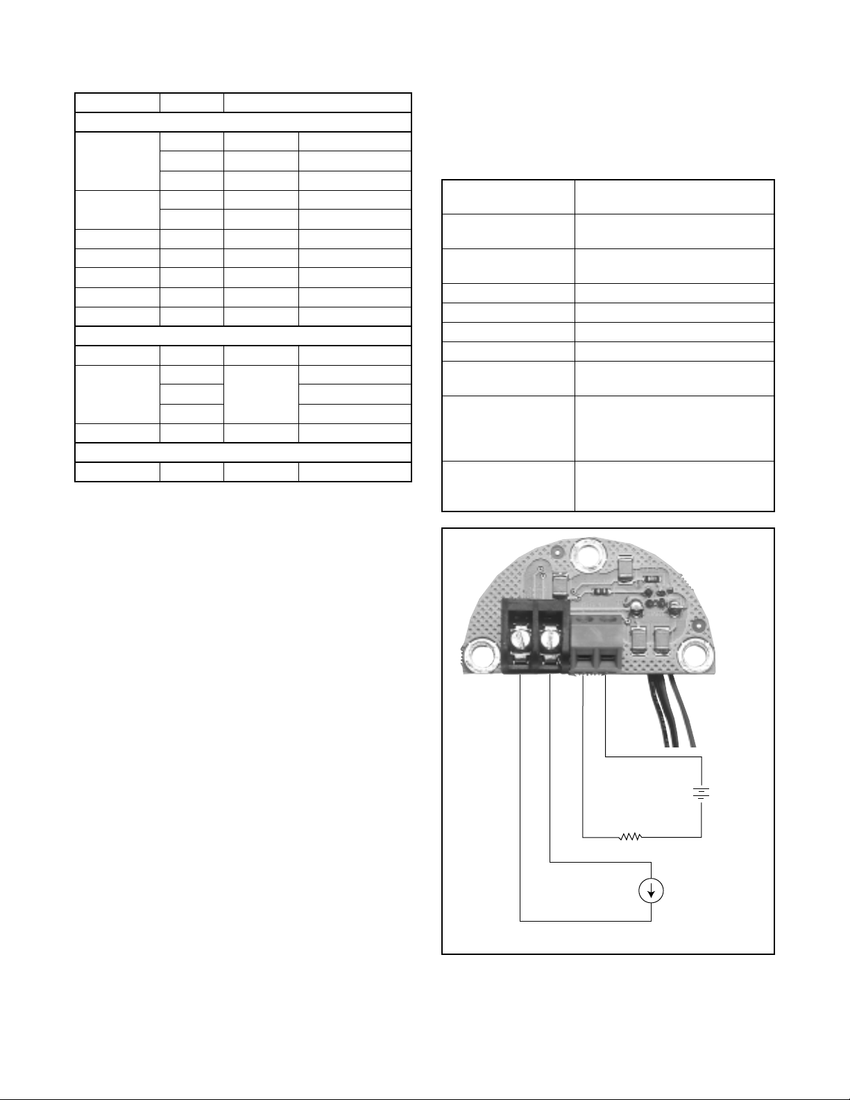
Table VIII: Logix Mounting Kits (Continued)
Model Size Mounting Kit
Masoneilan (Linear Actuators, cont.)
25 10125644
71 Domotor
88
47 B 10125702
48 B 10125702
“D” Domotor 200 10127467
71-2057AB-D 10129359
71-40413BD 10129461
33 B 10125542
35
70 10 10125542
37/64 10127426
* Adjustable Mounting kit 10126736 may be needed if
handwheels are used.
50 10125645
100 10125646
6 10124595
16 10126752
Masoneilan (Rotary Actuators)
4
101255426
7
Va nguard
vided between the supplies powering the Logix
unit and the analog output board.
Available for explosion-proof and safe applications
•
(CSA, FM).
Specifications
Potentiometer Range
of Rotation
Po wer Supply Range
Maximum Load
Resistance (ohms)
Current Signal Output 4-20 mA
Linearity 1.0% F.S.
Repeatability 0.25% F.S.
Hysteresis 1.0% FS
Operating
Temperature
Ambient
Temperature
Po wer Supply
Effects
40° to 95°
12.5 to 40 VDC
(24V DC typical)
(Supply Voltage - 12.5) / 0.02
-40° to 185° F
(-40° to 85° C)
For a 100° F (38° C) change in
ambient temperature, maximum
zero shift is 0.4% FS, maximum
span shift is 0.7% FS
Out put signal change is less than
0.05% FS when supply voltage is
varied between 12.5 and 40 VDC
4 to 20 mA Analog Output Retrofit
General Information
The Logix 1200e digital positioner/controller can be
retrofitted to provide an anal og feedback signal of the
stem position. This position feedback option has the
following features and specifications:
Does not in terfere with positioner operation.
•
Zero and span adjustments of the feedback signal
•
are independent of the positioner and can be
adjusted manually.
Output follows actual position of valve, including all
•
failure modes of positioner except loss of power. An
output of 3.15 mA is transm itted with loss of power
to the analog output board.
Immune to RFI/EMI disturbances.
•
Can be retrofitted in the field.
•
CAUTION: Because the analog output board
shares common signals with the Logix internal
circuitry, the two units cannot be powered by
the same external power supply or by power
supplies that share a common reference.Galvanic isolation of at least 50 VDC must be pro-
+
Positioner Command
Current Loop
(Logix Input)
CAUTION: Isolated power sources required.
+
––
Position Feedback
Current Loop
(Logix Output)
R
Load
–
12.5 to
40 VDC
Power
Supply
+
–
4 to 20 mA
Current Source
+
Figure 21: Analog Output Board Power
44-24 Flowserve Corporation, Valtek Control Products, Tel. USA 801 489 8611
Page 25

Terminal Board
Connection
Span Adjustment
Zero Adjustment
DIR/REV Switch
Potentiometer
Connections
Control Board
Connection
Figure 22: 4-20 mA Analog Output Board
Calibration
To calibrate the Logix 1200e or 1200e digital positioner equipped with analog output, follow the procedure outlined below:
1. Wire the position transmitter in series with a 12.5 to
40 VDC power supply and a milliamp meter.
CAUTION: Do not apply a voltage greater than
40 volts to transmitter terminals or the circuit
will be damaged.
2. Be certain the direct/reverse switch is set to provide
the desired output signal action. In the DIR position, a counterclockwise rotation of the potentiometer shaft (when looking at the label side of the
potentiometer) will cause the output signal to
increase. In the REV position, a clockwise stem
rotation causes the signal to increase. Perform a
stroke calibration whenever the direct/reverse
switch is changed.
WARNING: Keep hands, hair, clothing, etc.
away from moving parts when operating the
valve. Failure to do so can cause serious injury.
3. Stroke the valve to the close position.
4. Referring to Figure 22, adjust the zero adjusting
screw with a small, flathead screwdriver until the
meter reads 4 mA DC.
5. Stroke the valve to the open position.
6. Adjust the span adjusting screw until the meter
reads 20 mA DC.
7. Stroke the valve to the closed position and recheck
the meter for 4 mA DC. Some fine tuning of the calibration may be required. Repeat steps 3 through 7
until satisfied.
Retrofitting to a Logix 1200e Digital Positioner (with Circular Window in the Main Cover)
As shown in Figure 23, th e newer model of the Logix
digital positioner has a circular window in the main
cover (as opposed to a diagonal, oblong window in the
earlier model ). To retrofit Logix digi tal positioner to 420 mA analog output, use the following procedure:
1. Remove the main cover (Figure 29).
2. Remove the lower and middle screws holding the
control board in place; disc ard thes e screws.
3. Place the analog output board on the lower por tio n
of the control boa rd an d s ec ure wit h th e t wo lon ger
screws (6 x 32 1.25-in.) provided (Figure 33).
4. Unplug the orange/red/brown or brown/red/orang e
three-wire-set from the collector board.
5. Plug the orange/red/brown or brown/red/orange
three-wire-set into th e correct receiver in the analog output board (Figure 26).
6. Plug the three-wire set from the analog output
board into the rec eiver on the collector bo ard (that
previously had held the orange/red/brown or
brown/red/orange wire-set).
Flowserve Corporation, Valtek Control Products, Tel. USA 801 489 8611 44-25
Page 26

7. Connect the blue/yellow two-wire-set from the user
interface board to the remaining receiver on the
analog output board (Figure 27).
NOTE: On some boards both set of wires are
red/black but have different connectors - only one
set will be able to be plugged into the analog output
board.
8. Replace the main cover.
Retrofitting to a Logix Digital Positioner (with Diagonal Window in the Main Co ver)
As shown in Figure 28, th e earlier model of th e Logix
digital position er has an oblong, diagonal win dow (as
opposed to a circul ar window in t he newer model). To
retrofit an existing Logix dig ital positioner to 4-20 mA
analog output, use the following procedure:
1. Remove the main cover and the user interface
cover from the Logix unit (Figure 29).
2. Disconnect the ribbon cable that conn ects th e control board from the collector board.
3. Remove the three screws holding the control board
in place. Discard two of the screws .
4. Remove the control board from the Logix unit
(Figure 30).
5. Disconnect the cable that goes from the user interface board to the collector board.
6. Remove the three screws holding the user interface
board in place. Save these scr ews as well as the
O-ring that goes between the user interface board
and the housing (Figure 31).
7. Install the new user interface board with its two
connectors in serted into the cavity of the housing.
Make sure the O-ring is between the u ser inte rface
board and the housing (Figure 32).
9. Feed the user interface two-wire-sets in the housing, placing the wires in the trough at the bottom of
the housing. Connect the r ed/black two-wire-set to
the collector board where the old user interface
wire-set was connected. Pull the new blue/yellow
feedback two-wire-set so that it is next to the
red/black two-wire-set on the collector board.
NOTE: With some boards both sets of wires are
red/black but have different connector s
. The feedback wire-set will be co nnected later t o the analog
output board.
10.Carefully replace the control board, ensuring that
the clear pressure hose found inside the Log ix unit
is not pinched.
11.Place the analog outp ut board on the lower portion
of the control board and secure wit h the two longer
screws provided. Secure the top of the control
board with the original shorter screw (Figure 33).
12.Connect the contro l board ribbon cable to the collector board.
13.Unplug the orange/red /brown or brown/red/orange
wire set from the collector board.
14.Plug the orange/red/brown or brown/red/orange
wire set into the co rrect receiver in the a nalog output board.
15.Plug the three-wire-set from the analog output
board into the receiver on the coll ector board that
previously held the orange / red / brown or brown /
red / orange three-wire-set.
16.Connect the blue/yellow two-wire-set from the user
interface board to the remaining receiver on the
analog output board.
NOTE: With some boards,
both two-wire-sets are red/black but have different
connectors - only one set will be able to be plugged
into the analog output board
. Complete the installation by placing the Quick-Cal sticker on t he control
board can and the user interface sticker in the user
interface cover (Figures 14 and 15).
8. Install the three screws to secure the user interface
into the housing. Tighten to hand-tight.
44-26 Flowserve Corporation, Valtek Control Products, Tel. USA 801 489 8611
17.Replace the main cover and the user interface
cover.
Page 27

Figure 23: Logix 1200e Positioner with
Circular Window Design
Figure 26: Installation of Three-wire-set to
Analog Output Board
Figure 24: Logix Positioner with
Cover Removed
Figure 27: Completed Installation of
Analog Output Board
Figure 25: Installation of
Analog Output Board
Flowserve Corporation, Valtek Control Products, Tel. USA 801 489 8611 44-27
Page 28

Figure 28: Logix Positioner with
Diagonal Window Design
Figure 29: Logix Positioner with
Cover Removed
Figure 31: Removal of
Old User Interface Board
Figure 32: Installation of
New User Interface Board
Figure 30: Removal of Control Board
44-28 Flowserve Corporation, Valtek Control Products, Tel. USA 801 489 8611
Figure 33: Installation of Analog Output
Page 29

Figure 34: Sticker Application Figure 35: Completed Installation of
Analog Output Board and
User Interface Board
Flowserve Corporation, Valtek Control Products, Tel. USA 801 489 8611 44-29
Page 30

Troubleshooting
Introduction
This guide is designed to assist the user in troubleshooting the Logix™ 1200 digital positioner. The Logix
1200 positioner is a two-wire, HART communicationbased device, and is used in conjunction with
Tal k™
and
SoftTools™
software or the HART 275
Val-
handheld communicator. As part of this troubleshooting guide, a number of recommendations are provided, which should improve operation and allow for
accurate configuration.
Theory of Operation
NOTE: Var iable names found in Figure 18 are used in
ValTalk software and can be found in the Measured
Values Status screen.
The Logix 1200 digi tal position er receives power from
the two- wire , 4-20 mA inp ut si gna l. Ho w ever, sinc e thi s
positioner utilizes HART communications, two sources
can be used for the command signal: analog or digital.
With the analog source, the 4-20 mA signal is used for
the command source. With the digital source, the level
of the input 4-20 mA signal is ignored and a digital signal (sent via HART) is used as the command s ource.
The command source can be accessed with
SoftTools
software, or the HART 275 communicator.
Whether in analog or a digital source,
ValTalk
0 percent
always defined as the valve’s closed position and
percent
is always defined as the valve’s open pos it ion .
With the analog source, the 4-20 mA signal is con-
or
is
100
verted to a percentage. During loop calibration, the
signals corresponding to 0 percent and 100 percent
are defined.
At this point, the command value is pass ed through a
characterization/limits modifier block. The positioner
no longer uses cams or other mechanical means to
characterize the output of the position er. This function
is performed by the software, which allows for user
adjustment in the field.
The positioner has two bas ic modes:
characterization. In the
tom
Linear
and
Linear
Cus-
mode, the command signal is pa ssed straight through to the control
algorithm in a 1:1 transfer. If
Custom
characterizatio n
is enabled, the command source is mapped to a new
output curve through a 21-point, user-defined curve. In
addition, two user-defined features,
(Minimum Position Cutoff), may affect the final
MPC
Soft Limits
and
command signal. Th e actual command being used to
position the stem is called
Control Command
is the actual positio ning command
Control Command
. The
after any characterization or user limits have been
evaluated.
The Logix 1200 positioner uses a two-stage, stempositioning algor ithm. The two stages are comprised
of an inner-loop, spool control a nd an outer-l oop stem
position control. Referring to Fi gure 1 8, the stem position sensor provides a measurement of the stem
movement. The
against the
Stem Position.
Control Command
If any deviation exists, the
is compared
control algorithm s ends a s ignal to t he inner- loop control to move the spool up or down, depending o n the
deviation. The inner-loop then quickly adjusts the
Air Supply
Command
Source
4–20
(Analog Mode)
44-30 Flowserve Corporation, Valtek Control Products, Tel. USA 801 489 8611
Analog
Digital
Command in
(Digital mode)
Linear Mode
Characterization
Soft Limits
MPC
Control
Command
+
Deviation
Position
Control
Algorithm
P
max
P
min
G
mult
Integration Summer
Inner Loop Offset
Inner-Loop
Hall Sensor
D/A Output
Percentage
Output
Sensor
Modulator
Coil Current
Inner Loop
Spool Control
Tubed A TO
Stem
Position
Sensor
Page 31

spool position. At that point, the actuator pressures
change and the stem begins to move. The stem movement reduces the deviation between
and
mand
the deviation goes to zero. The control algorithm is
both propor tional and integral. (This algo rithm will be
further explained later in this guide.)
The following detailed example explains the control
function:
Given:
Given these conditions, 12 mA represents a
mand Source
is disabled, so the
the
Control Command.
Stem Position
the desired positi on, th e spo ol valve will be p ositi oned
so that no airflow is allowed to either side of the actuator. This is commonly called the
position.
At this point, change the input signal from 12 mA to 16
mA. The positioner sees this as a
of 75 percent. With
trol Command
difference between
tion,
cent is the present stem position. With a positive
deviation, the control algorithm sends a signal to move
the spool up from its present position. As the spool
moves up, the supply air is applied to the bottom of the
actuator and air is exhausted fr om the top of the ac tuator. This new pressure differential causes the stem to
start moving towards the desired position of 75 percent. As the stem moves, the
decrease. The control algor ithm begins to reduce the
spool opening. This pr oc ess c onti nues until the
goes to zero. At this point, the spool w ill retur n to
tion
its null or balanced position. Stem movement stops
and the desired stem position is now achieved.
One important parameter is now introduced – the
inner loop offset. Referring to Figure 18, a number
designated as the In ner
output of the control algorithm. For the spool to remain
Stem Position.
Unit is in
Custom
(therefore characterization is
Soft limits
Valve has zero deviation with a present input
signal of 12 mA
Loop calibration: 4 mA = 0% command, 20
mA = 100% command
Actuator is tubed ATO (Air-to-Open)
i.e. Deviation = 75% - 50%= +25%, where 50 per-
Analog command source
characterization is disabled
and
of 50 percent.
Command Source
is also at 50 percent. With the stem at
becomes 75 percent. Deviation is the
This process continues un til
are disabled
MPC
Custom characteri zation
Since zero deviation exists, the
null
characterization , the
Linear
Control Command
Loop Offset
Control Com-
and
)
Stem Posi-
begins to
Devia-
Linear
is passed 1: 1 to
or balanced spool
Command Source
Deviation
is added to th e
Com-
Con-
in its null or balanced position, the control algorithm
must output a non-zero spool command. This is the
purpose of the inner loop offset. The value of this number is equivalent to th e signa l that must be sent to th e
spool position con trol to br ing it to a null pos ition with
zero deviation. This parameter is impor tant for proper
control and will be discussed further in the
section.
Tuning
Control
and
Mounting and Installation
Air Supply Requirements
NOTE: The Logix 1200 positioner requires an external
air filter (preferably the Valtek coalescing air filter).
The air supply must co nform to ISA Standa rd S7.3 (a
dew point at least 18° F/10° C below ambient temperature, partic le size below 5-mic rons and oil content no t
to exceed one part per million); however, filtering for 1micron particle size is recommended. For a model with
advanced diagnostics (L ogix 121X), the inter nal pressure sensors are rated for continuous ope ration up to
150 psig (10.3 barg).
Electrical Wiring
First, verify the polarity when making the field termination connection. The Logix 1200 positioner is reverse
polarity protected. With a 4-20 mA source connected,
verify that the positioner’s LED is blinking to determine
if the electronics are r unning. Only one LED wi ll blink
at any given time. Remember the 4-20 mA input current signal must be gre ater than 3.5 mA to power-up
the Logix 1200 positioner. Never connect a voltage
source directly acros s the Logix 1200 terminals. The
current must always be limited for 4-20 mA operation.
NOTE: The Logix 1200 posit ioners carr ies an intri nsically safe barrier rating of 125 mA. Cu rrents up to 125
mA will not damage the device.
Frequently Asked Questions
Q: My DCS uses 24 VDC. Can I run a Logix 1200
positioner?
A DCS output current card does run from 24 VDC
A:
but the card regulates the actua l current output. However, if the 24 VDC were applied directly across the
terminals, nothing would limit the current and the
Logix 1200 field termination board co uld be dam aged.
The important point to remember is that it does not
matter what the current source voltage supply is as
long as the current is limited in the 4-20 mA range.
Flowserve Corporation, Valtek Control Products, Tel. USA 801 489 8611 44-31
Page 32

Q: I accidentally placed a voltage supply across the
Logix 1200 positioner. How do I know if I damaged
something?
The typical failure in an over-current situation is a
A:
shor t circuit. Your loop current will be mai ntained but
the Logix 1200 control board will receive no power.
With power removed from the Logix 1200 positi oner,
use an ohmmeter to measure the ohms across the terminals. If the reading indicates a short (close to zero
ohms), the field ter mination board must be replaced.
Make sure the positive lead is on the ‘+’ ter minal and
negative lead is on the ‘-’ terminal when measuring the
resistance.
Q: What is the input resistance of the Logix 1200
positioner?
The Logix 1200 positione r does not have a simple
A:
resistive input. When measuring the voltage across
the Logix 1200 positioner, it only varies sligh tly when
the current is changed from 4 mA to 20 mA (11.7 VDC
to 12 VDC nominal). This is because the Logix 1200
positioner is an active device. For the Logix 1200 positioner,
(Effect ive resistance is the resistance at a given current.) To explain further:
Effective Resistance = (Terminal Voltage)/Current
For example, at 20 mA: Effective resistance = 12
VDC/0.02 A = 600
The Logix 1200 positioner has a specification of 600
@
NOTE: One cannot measure a cross the terminals of
an unpowered Logix 1200 positioner and find the
effective resistance.
effective resistance
Ω
20 mA.
is commonly referred to.
Air Action
Air-to-open and air-to-close are determined by the
actuator tubing and not the software. When air-action
selection is chosen during configuration, that selection
tells the control which way the actuator is tubed. Verify
that the actuator tubing is co rrec t prior to a stroke calibration. The top output port is called
should be tubed to the side of the actu ator that must
receive air to begin the correct action. For example, for
an air-to-open linear actuator,
tubed to the bottom of the actuator.
Output 1
Output 1.
should be
It
Linear vs. Rotary
The positioner has two configuration settings:
and Rotary.
gains are adjusted bas ed o n th e l inkag e an gl e of ro tation. The linear se ttin g a ll ows for linkage ro tati on up t o
65°. The rotary sett ing allows for linkage rotation up to
For better resolution, stem position sensor
Linear
95°. These setting s only determine the angle of sensor rotation and do not affect control parameters.
If a positioner is set to linear co nfiguration and a red
LED blinks after calibration, the m ost common cause
is the sensor movement was greater than 65°. This
can occur if the roller pin was placed in the wrong hole
on the follower arm or the stem clamp is placed too
high on the actuator stem. The take-off arm should
always be level with the stem clamp on linear
mountings.
The Logix 1200 pos itioner has an elec trical measur ement range of 95°. That is, the elec tronics will sense
stem position over a 95° range. With a rotary valve,
the typical rotation is 90°. When connecting a Logix
1200 positioner to a rotary valve, the 90° valve rotation
is centered w it h in th e 1 0 0° electrical range. If mechanical movement falls outside the electrical measurement range, the positioner can have a dead band at
one end of travel in which valve movement cannot be
sensed.
Frequently Asked Questions
Q: How do I know if the rotary linkage is centered
within the 95° electrical range?
The slot in the take-off ar m has enough clearance
A:
around the roller pin to move the follower arm slightly.
Move the valv e to the fully closed position. At this position, move the follower arm within the slot clearance. If
Ω
the valve does not respond by making an adjustmen t,
linkage adjustment is necessary. Repeat this test at
the fully open position.
To adjust the stem position linkage, use the Logix
able number 2.
the
Measured Value
Hall pot sensor A/D
under
View Variables
also be viewed from the HART 275 communicator in
the
Status/Technician
mechanical fail position (no pres sure applied), sl ightly
move the follower arm while watching
If the number does not change, the arm is not cen-
2.
tered in the electrical range. (The number will jump
one or two counts due to nois e at a fixed position an d
should not be considered a change. It should move
greater than 10 to 20 counts if the linkage is centered
correctly.) If necessary, rotate the take-off arm or feedback sensor to bring the linkage in range.
NOTE: Due to the speed of HART communication,
allow two to three seconds for the display to update
after each adjustment.
This procedure is only nec essary on a rotar y mounting. For linear mountings, the red LED will blink if 65 °
travel is ex ceeded. Refer to the Calibration sec tion for
further information on stroke calibration errors.
This can be viewed as A/D feedback in
screen in
value in the
in
menu. With the valve in its
ValTalk
SoftTools TechCheck.
software or the
Condition
variable number
vari-
screen
It can
44-32 Flowserve Corporation, Valtek Control Products, Tel. USA 801 489 8611
Page 33

Calibration
Quick-Cal
The
Quick-Cal™
valve can be stroke calibrated without using
SoftTools
NOTE:
tion in the event a HART interface is not av ailable. T his
allows the valve to be placed in operation. However,
full configuration can only be accomplished through
ValTalk, SoftTools or the HART 275 handheld communicator.
The
Quick-Cal
tion parameters. Any previous configuration or store d
information is not a ffec ted. If the positioner loop cur rent has not been calibrated in the field, it defaults to a
loop calibration of 4 mA b eing a 0 percent command
and 20 mA being a 100 percent command . This cannot be changed without HART interface. If the loop
has been calibrated in t he field, these se ttings will not
be affected by the
Regarding the
the third
transfer characteristic from 4-20 mA input signal to
Control Command
to
Custom,
The factory custom characterization curve is equal
percent. If the characteriza tion curve has been modified in the field, the modified curve will be used.
NOTE:
if the Quick-Cal button is presse d for five seconds. If
the Quick-Cal function is not used, the DIP switch settings have no effect on positioner operation.
Command 0% Calibration Flag
During loop calibration, the Logix 1200 positioner
checks if the value read with the current at the desired
0 percent command level is within range. This error
normally ind icate s that the lo op curre nt was set above
21 mA during this part of the calibration procedure.
(See
How to Clear Flags
Command 100% Calibration Flag
During loop calibration, the Logix 1200 positioner
checks if the value read with the current at the desired
100 percent command level is within range. This error
normally ind icate s that the lo op curre nt was set above
21 mA during this part of the calibration procedure.
(See
How to Clear Flags
Function
function is a method by which the
ValTalk
software or the HART 275 communicator.
This feature is provided to all ow stro ke cali bra-
function only affects the stroke cali bra-
Quick-Cal
Linear vs. Custom DIP
Quick-Cal
custom characterization will be enabled.
The DIP switch settings only becom e effective
DIP switch is set to
will be 1:1. If the DIP switch is set
function.
switch setting: If
Linear,
section on page X.)
section on page X.)
or
the
Position 0% Calibration Flag
During stroke calibration, the Logix 1200 positioner
checks if the linkag e is placing the stem p osition sensor in range. If the valve stroke causes stem position
measurement to move out of range in the clos ed p os ition, a
stem will stop in the closed positi on and the red LED
will blink. The linkag e must then be adjust ed to bring
the sensor in range. (See How to Cl ear Flags sectio n
on page X.)
NOTE:
indication. If the lin kage is out of range, the LEDs ca n
be used as an adjustment gu ide. The LED will ch ang e
from red to yellow when the linkage is brought into
range. Refer to Stroke Calibration Section.
Position 0%
The Logix 1200 po sitioner has a special LE D
flag will be generated. T he valve
Position 100% Calibration Flag
During stroke calibration, the Logix 1200 positioner
checks if the linkag e is placing the stem p osition sensor in range. If the valve stroke causes stem position
measurement to move out of range in the open position, a
stem will stop in the open position and the red LED will
blink. Linkage must be adjusted to bring the se nsor in
range. (See
NOTE:
indication. If the lin kage is out of range, the LEDs ca n
be used as an adjustment gu ide. The LED will ch ang e
from red to yellow when the linkage is brought into
range. Refer to Stroke Calibration section.
Position 100%
How to Clear Flags
The Logix 1200 po sitioner has a special LE D
flag will be generated. The valve
section on page X.)
Command Span Flag
Command span is a check duri ng loop calibration to
verify that the input signal changed between a 0 percent reading and a 100 percent reading. The most
common cause for a
to change the cur rent source when asked to set the
100 percent current level. Clear a
Flag by performing a
Command Span
Command
flag is forgetting
Command Span
calibration correctly.
Position Span Flag
Position span is a check during stroke calibration to
verify that the valve stem moved. The algorithm waits
to detect if no movement is detected when the valve is
automatically stroked open. Although the algorithm
waits for valve move men t, if a large ac tuator (size 20 0
or 300) is run at low pressures, it may not detect
movement and stop with a
thing that could prevent the valve from stroking will
generate a
malfunctioning spool valve). Clear a
signal by correcting the problem that is preventing the
valve to stroke and re-calibrate the stroke.
Position Span Error
Position Span Error.
(no supply pressure or
Position Span
Any-
flag
Flowserve Corporation, Valtek Control Products, Tel. USA 801 489 8611 44-33
Page 34

Control and Tuning
Setting P+I Parameters
Using
ValTalk or SoftTools
parameters can be selected:
(with
Factory A
beginning at the smalles t ac tuat or size
and the lowest gain settings). Using the
option, one can set indivi dual tuning parameters. The
software manuals outline the procedure to adjust
these tuning parameters; however, a few key points
are mentioned below.
Maximum Gain, Minimum Gain, and
These three parameters are related by the following
formulas:
software, default tuning
Fa cto ry A, Factory B,
etc.
Advanced
Gain Multiplier:
tion, it can add overshoot as well as cause the
positioner to hunt if too la rge. The recomm endation is
that maximum and minimum gains be adjusted while
leaving
Integral Gain
fixed at 10. Integration is disabled below a stem position o f 5 percent a nd above a
stem position of 95 per cent. Thi s is to prevent integration windup from calibration shi fts due to lower pressure or a damaged seat, which may prevent fully
closing the valve.
The
Integral Summer
within the Logix 1200 posi tioner
is clamped at +20.00 % and -20.00%. If the i ntegration
summer (
Variable No.15
in
ValTalk or SoftTools
software) is fixed at +20% or -20 %, it usually indic ates a
control problem. Some reasons for a clamped int egration summer are listed below:
Proportional Gain = Maximum Gain - |deviation| x
Gain Multiplier
If Proportional Gain < Minimum Gain, then Proportional Gain = Minimum Gain
Maximum Gain
Gain Multiplier
(Determines Slope)
Proportional Gain
Minimum Gain
Small Steps Large Steps
deviation
Figure 19: Logix 1200 Proportional Gain
This algorithm al lows for quicker response to smaller
steps yet stable control for large steps. Setting the
Gain Multipl ie r
to zero or
Max Gain = Min Gain
results
in a typical fixed proportional gain.
The higher the
Gain Multiplier,
the smaller t he re quir ed
deviation before the gain increases. Default values
upon initiating a RESET are
Minimum Gain = 1.0,
and
Maximum Gain = 2.0,
Gain Multiplier = 0.05.
These values will allow stable control on all Valtek
actuator sizes.
The
Integral Gain
is used primarily for deviations due
to temperature drift wi thi n t he i nne r lo op s po ol co ntro l.
The factory default value is 10. Althou gh higher numbers can speed the tim e it takes to reach zero devia-
Stroke calibration incorrect
•
Any failure which prevents stem position movement,
•
such as stuck spool, handwheel override, low
pressure
Incorrect inner loop offset
•
Loss of air supply on a fail in place actuator
•
Writing a zero to
Summer. The
Integral Gain
Integral Gain
will clear the Integration
can then be returned to its
original value.
Referring to Figure 1 under
Theory of Operation
, three
control numbers are sum med to drive the inner loop
spool position contr ol: propo r tion al gain, in tegral summer, and inner loop offset.
Inner Loop Offset
is the
parameter that holds the sp ool in th e ‘null’ or ‘balance’
position with a cont rol deviation of zero. This value is
written by the factory du ring produc tion and is a fun ction of the mechanical and electrical spool sensing tolerances. However, if the driver module assembly is
replaced or if the soft ware Reset is performed , adjus ting this value may be necessary. The method outlined
below should be used to adjust the
Inner Loop Offset:
NOTE: Logix 1200 positioners with embedded code
(revision 0.2 and higher) will automatically calculate
this value during a stroke calibration.
ValTalk Software
1. From the
Advanced Tuning
Screen send a 50 per-
cent command usin g 4-20 mA signal or digital m ode.
NOTE: Digital mode must be set in Instrument Status screen prior to entering Advanced Tuning
screen.
2. Allow the position to stabilize.
3. Record the
D/A output %
reading (displayed on the
upper right hand side). This number will vary
slightly; therefore, estimate an average over a brief
period of time.
44-34 Flowserve Corporation, Valtek Control Products, Tel. USA 801 489 8611
Page 35

4. Write this number to the
SoftT ools T echCheck Software
1. From the
ILO
2. Allow the position to stabilize.
3. Write the value shown for
Loop Offset.
NOTE: The actu ator must not be saturated (D/A output = 0) while setting the Inner Loop Offset.
HART 275 Handheld Communicator
1. Send a 50 percen t c om man d u sing 4- 20 mA sig nal
or digital mode.
2. Proceed to the
3. Locate the
4. Divide this number by 2.5 V and multiple by 100
percent. Example: D/A Output Voltage = 1.25 V.
Therefore: 1.25 V/2.5 V x 100% = 0.5 x 100% =
50%.
5. Write this percentage value to the
Custom Tuning
button.
Status/Technician
D/A Output Voltage.
Inner Loop Offset.
screen, select the
D/A Average to Inner
menu.
Inner Loop Offset.
Adjust
4. Inspect the coalescing filter element in the spool
valve cover for signs of oil, water and debris that
may have come from the air supply. (A clean filter is
white.)
5. Remove the two Phillips-head screws holding the
spool valve to the housing. Inspect the free movement of the spool by car efully sliding the block up
and down on the spool abo ut 0.25 inches (6 mm).
The block should slide on the s pool with no resistance. Carefully remove the block from the spool,
ensuring it is removed concentric with the spool.
6. Inspect the block and spool for oil, water, debris
and wear. If oil, water and/or debris are found, the
spool and block can be cleaned with a no n-res idue
cleaner, lint-free cloth and soft-bristle brush. If wear
is found, replace the driver module assembly or
spool valve. Refer to Spool Valve and/or Driver
Module sections.
7. Before re-assembly, verify the three O-rings are
correctly placed in the counter-bores on the
machined platform where the spool valve block is to
be placed.
Digital Filter
This parameter controls a noise reduction filter used
on the readings obtained from command and stem
position sampling. This filter is internal to the positioner software and is not associated with the external
HART filter. This parameter setting should remain at
0.5.
Spool Valve
The spool valve is a four-way directional valve with
precision features to provide optimal con trol and lowair consumption. To help prevent a malfunction o f the
spool valve, the positioner supply air must conform to
ISA Standard S7.3 (a d ew p oint at least 18 degrees
below ambient temperature, particle size below 5microns, oil content not to exceed one part per million). The standard Valtek coalescing filter is highly
recommended to help meet these requirements.
Small par ticles, oil that has varnishe d, corrosion, ice,
burrs, and extreme wear could cause the spool valve
to act abnormally. If the spool valve is suspected of
sticking, check it by performing the following procedure:
1. Make sure the valve is bypassed or in a safe
condition.
2. Disconnect the power and air supply to the unit.
3. Remove the spool valve cover by removing the
screw and sliding the cover assembly backwards
until the tab is clear of the slot.
8. Carefully slide the block over the spool, using the
machined surface of the hous ing base as a register. Slide the block toward the driver module until
the two retaining holes line up with the threaded
holes in the base. If re sistanc e is stil l encountered ,
re-clean both parts or replace the driver module
assembly or spool valve.
HART Communication
Current Source Interference
HART communication super imposes two frequencies
(1200 Hz and 2200 Hz) on the DC 4-20 mA current
signal. Some current s ources (DCS or 4-20 mA calibrator) can interfere with the HART signal. Thi s may
prevent communication with ValTalk or SoftTools software or the HART 275 handheld communicator. Intermittent communication may also be the result of a
HART in co mpa t ible current source. In t his ca se, a filter
is necessary between the current source and Logix
1200 positioner to allow HART communication.
Valtek HART Filter (VHF)
Figure 2 0 & Figure 21
Flowserve offers a filter (Valtek part no. 10079944)
that must be used on each 4-20 m A line if the current
source interferes with communi cation. The filter does
not affect the DC current but prevents the source from
affecting the HART frequencies. The filter c omes in a
DIN rail mount package.
Flowserve Corporation, Valtek Control Products, Tel. USA 801 489 8611 44-35
Page 36

NOTE: This filter is not rated for use in hazardous
areas. It should be located between the current source
and the barrier in intrinsically safe applications.
Figure 20: HART VHF Filter
Frequently Asked Questions
Q: How do I know if I need a VHF?
If the current source is interfering w ith communica-
A:
tion, it will affect the ValTalk or SoftTools s oftware and
the HART 275 handheld communicator. If the positioner communicates to
275 handheld com municator when using one cu rrent
source (for example, a 4-20 mA current calibrator) and
not the DCS, it indicates a filter is nec essar y with that
current source. Some 4-20 mA calibrators that work
without a filter are l is ted be low. If one of these is available, try to connect with ValTalk or SoftTools software
or the HART 275 handheld communicator again. If
communications are established while using one of
these sources, but fails on the original source, a filter
is needed.
The following handheld 4-20 mA calibrators do not
require a filter:
ValTalk
software or the HART
Rochester Instrument Sy st ems (RIS) CL-400 2
•
Unomat UPS-I
•
HART Modem
The HART modem is a device that connects to the
serial communications port of a computer. This
modem converts the RS-232 COM po r t signals to the
HART signal. A HART modem is required to use
ValTalk
MUX can be used in its place. The HART modem
takes power from the RS-232 COM port lines. If us ing
a laptop computer that is operating on its internal
battery, HART communi cation may become erratic as
the batteries begi n to lose their charge. This is due to
a reduction in HART modem power. At this point,
recharge the batter ies or apply AC adapter power to
correct the problem.
software, and is optional in SoftTo ols since a
Connections
When using ValTalk or SoftTools software or the HART
275 handheld communicator, the leads can be connected anywhere across the 4-20 mA current signal.
The leads are not pol arity sens itive. When using a filter, the connection must be made between the filter
output and the Logix 1200 positioner (Fi gure 21).
Cabling
Because HART protocol uses fre quencies of 12 00 Hz
and 2200 Hz to communicate, cable type and l ength
must be considered. High capacitance/foot cable or
long runs ca n cause erratic communication. Refer to
instructions for correct cable requirements.
Intrinsically Safe Barriers
When selecting an intrinsically safe barrier, make sure
the barrier is HART-compatible. Although the barrier
will pass the loop current and allow nor mal posi tioner
control, if not compatible, it may prevent HART
communication.
Altek Model 334
•
Figure 21: HART VFH Filter Schematic
44-36 Flowserve Corporation, Valtek Control Products, Tel. USA 801 489 8611
Page 37

Alarms
Introduction
The Logix 1200 positi oner has s everal internal alar ms
that monitor electronics operation. An internal alarm
causes the red LED t o blink. Al arm s can be viewed in
the
play (by right-clicking on the al arm LED in the lower
right-hand cor ner of any screen), Aler t Details button
with
with the HART 275 handheld communi cator. ‘Alarms’
differ from ‘alerts’ in that the action of the positioner
may be erratic during the alarm conditions, while
alerts warn a predefined, user-configured condition
has occurred that may require service in the near
future. Alarms ca us e th e r e d L ED to blink, wh il e a lerts
cause the yellow LED to blink.
12-bit A/D Reference Alarm
The Logix 1200 positi oner utilizes a 12-bit analog-todigital (A/D) converter to acquire command and stem
position readings. If the precision reference used by
the A/D drifts out side rated tolerances, the
Reference Alarm
will cause change i n calibration and control readings.
If a continuous
main PCB assembly must be repla ced. Re fer to spare
parts kit numbers section.
1.23 V Reference Alarm
The
position control. If it dr ifts outside normal tolerances,
the
continuous
PCB assembly must be replaced. R efer to spare parts
kit numbers section.
12 bit D/A Alarm
The Logix 1200 positioner utilizes a 12-bit digital-toanalog (D/A) conver ter to send a control signal from
the micro-controller to the inner loo p spool pos itionin g
circuit. The output of the D/A converter is independently measured to verify correct operation. A
D/A Alarm
a continuous
assembly must be replaced.
screen of
Alarm
So ft Too ls TechC heck
1.23 V Reference
1.23 V Reference Alarm
1.23 V Reference Alarm
indicates the D/A may be malfunctioning. If
12-bit D/A Alar m
ValTalk
will become active. A reference error
12-bit A/D Reference Alarm
software,
, or by using the
is used by the inner loop sp ool
will become active. If a
exists, the main PCB
View Alert
exists, the main
dis-
Hot Key
12-bit A/D
exists, the
12-bit
Temp erature Alarm
The main PCB assembly contains an ambient
temperature sensor. If the ambient temperature
reading moves outside the operating range (- 40° F to
185° F/-40° C to 85° C), the Temperature alarm
becomes active and the red LED blinks. If this alarm is
present and the ambient temperature reading is
incorrect, the main PCB assembly must be replaced.
Refer to spare parts kit numbers section.
Hall Sensor Alarm
As described in the
1200 positioner incorporates an inner loop, spool-positioning stage. A hall sensor is use d for spool control . If
the electronics sens e a problem with the sensor, the
Hall Sensor Alar m
sons for a
cable connection to the Collector Board Assembly or a
broken wire. In the rare event that the actual hall sensor is defective, the driver module assembly must be
replaced. Refer to spare parts kit numbers section.
Hall Sensor Alarm
Theory of Operation,
becomes active. Two common rea-
are a loose or missing
the Logix
Modulator Current Alarm
The pressure modulator is an electro-pneumatic
device that takes a current sig nal from the el ectronics
control and generates a pressure that moves the
spool. The Logix 1200 positioner is a loop-powered
device that must run on very low power. During operation, the pressure modulator current is monitored. If
the current draw is not within acceptable parameters
for the given control mode, the
becomes active and the red LED blinks. The
Alarm
magnitude of
Var iable No. 97
software), the Condition screen under View Vari-
Tal k
ables (
Status/Technician
municator). Listed below are some r easons for a
ulator Current Alarm:
Pressure modulator minimum pressure too low
•
Clogged or restricted orifice
•
Malfunctioning or missing cable connection to col-
•
lector board assembly
Stuck or sticky spool
•
Internal air leaks from tubing, orifice gasket or pres-
•
sure modulator
Modulator Coil C urre nt
in the I
SoftTools TechCheck
nstrument Status
screen (HART 275 handhe ld com-
Modulator Current
can be viewed as
screen (
software) or in the
Val-
Mod-
Flowserve Corporation, Valtek Control Products, Tel. USA 801 489 8611 44-37
Page 38

Board Current Alarm
The Logix 1200 posit ioner is a loop-powered device,
which must run on very l ow power. During o peration,
the current draw of the electronics is monitored. If current draw is excessive and would prevent operation at
3.7 mA, the
the red LED blinks. The most common cause is a
failed main PCB assembly. If the electronics’ current
draw is excessive, the Logix 1200 positioner w ill most
likely operate at higher currents (12 mA and above)
but may lose power at lower currents. This error
requires that the main PCB be replaced. Refer to
spare parts kit numbers section.
Board Current Al ar m
becomes active and
EEPROM Checksum Alarm
Configuration data is stored in EEPROM. When power
is lost, configuration information is retrieved from
EEPROM and operation resu mes. A check is done by
the micro-controller after a power-up to make sure
data saved in EEPROM has not been c orrupted. Th e
checksum is a number that is calculated based on
configuration data. It is a lso saved in EEPROM every
time data is stored. After a power-up, if this number
does not match the data in memory, an
Checksum Alarm
If this occurs, turn off the power to the Logix 1200
positioner, followed by turning on the power. If the
error does not cl ear, try saving the config uration data
again using
275 handheld communicator. If the previous configuration has not been saved, reset the device and re-co nfigure. If these steps still do not clear the error, the
main PCB assembly must be repla ced. Re fer to spare
parts kit numbers section.
is generated and the red LED blinks.
ValTalk
or
SoftTools
software, or a HART
EEPROM
Pressure Alarms
NOTE: Pressure alar ms are onl y available on models
with advanced diagnostics (Logix 121X).
Advanced diagnostic models add top, bottom and supply pressure sens ors on more current models (Logix
1210e) the supply sensor is not included, instead,
supply is calcu lated using the ot her pr essu re sen sors.
These sensor readin gs and alarms are only a ccessible from
handheld communicator when the configuration has
been set to
The
supply pressure is n ear the minimum positi oner operating pressure of 30 psig (2 .1 barg). If the LEDs alternate between red and green, the supply pr essure may
ValTalk
Loss of Pressure Alarm
or
SoftTools
Advanced.
software, or a HART 275
becomes active when the
be at the limit threshold . This alarm is meant to al ert
the user to low supply pressure as we ll as complete
loss of pressure.
Both the top and bottom s ensors are checked during
actuator calibration. If a ca libration readin g appears to
be out of range, the appropriate alarm will become
active. The pressure sens ors are located on the collector board assembly.
Alerts
MPC (Minimum Pos ition Cutoff)
The Minimum Position Cutoff (MPC) or tight shutoff
feature of the Logix 1200 positioner al lows the user to
control the level at which the comman d signal causes
full actuator saturation in the closed pos ition. This feature can be used to guarantee actua tor saturation in
the closed position or prevent throttling around the
seat at small command signal levels. This features
defaults to 1% from the factory (which means it is
enabled).
NOTE: The positioner automatically ad ds a 1 percent
hysteresis value to the MPC setting to prevent jumping
in and out of saturation when the com man d is close to
the MPC setting.
Frequently Asked Questions
Q: I set the MPC at 5 percent . How will the positioner
operate?
A:
Assume the present com mand signal is at 50 per-
cent. If the command signal is decreased, the positioner will follow the command until it reaches 5
percent. At 5 percent , the spool will be dr iven in order
to provide full actuator saturation. The positioner will
maintain full satu ration b elow 5 percent command signal. Now, as the command increases, the positioner
will remain saturated until the command reaches 6
percent. (Remember the 1 percent hysteresis value
added by the positioner). At thi s point, the stem position will follow the command signal.
Q: I have MPC set to 3 percent but the valve will not
go below 10 percent.
A:
Check to see if the l ower soft limit is e nabled. The
lower soft limit must be less than or equal to 0 pe rcen t
for the MPC to become active. If a positive lower soft
limit is written, this l imit will take prior ity over the MPC
feature.
44-38 Flowserve Corporation, Valtek Control Products, Tel. USA 801 489 8611
Page 39

Soft Limits
Unlike position alerts, soft limits prevent the stem position from moving below or above the configured limits.
If the command signal is trying to drive the position
past one of the limits, the yellow LED will blink but the
stem position will remain at the set limit.
Q: Will soft limits prevent the valv e from going to its fail
position?
A:
No.
Position Alerts
Position alerts notify the user the valve has traveled
past a configured limit. The default settings are -10
percent and 110 percent, which are outside normal
travel and therefore disabled. Position alerts only
notify the user a limit has been exceeded and do not
limit stem movement. Position alerts will cause the yellow LED to blink.
Cycle Counter
The cycle counter is another means of monitoring
valve travel. Unlike the travel accumulator, the stem
position must do two things to count as a cycle: 1)
exceed the cycle counter dead band and 2) change
direction. A cycle c ounter li mit can a lso be wr itten into
the positioner. If this limit is exceeded, th e yellow LED
blinks. The cycle counter must be reset to begin a new
count sequence. This must be done after the alert has
been triggered to reset the alert. Do this by clicking on
the reset button in
configuration section of the sof tware. With the HART
275 handheld communicator, resetting is accomplished by choosing
Cycle/Travel, Cycle Information (2), Reset Cycle
Counter (4).
Va lTa lk
or
SoftTools
Configure (3) Cycle/Travel Inf. (9),
software in the
and added to the travel accumulator. From this new
position, dead band high and low limits ar e again calculated.
For example, the Logix 1200 positioner has a default
dead band configuration of 20 percent . The valve has
a 4-inch (10 cm) linear stroke. When the valve first
powers up, the command signal is 50 percent. The
unit will calculate a high travel threshold of 70 pe rcent
(50 percent present position plus 20 percent dead
band) and a low travel threshold of 30 percent (50 percent present position minus 20 percent dead band).
As long as the stem position remains greater than 30
percent and less than 70 percent, no additions are
made to the travel accumulator. At this point, assume
the stem position moves to 80 percent, whi ch is outside the present dead band. The Logix 1200 positioner calculates the stem movement and adds this
number to the travel accumulator.
80% (present position) – 50% (previous) =
30% movement x 4-inch stroke = 1.2 inches
Therefore, 1.2 inches (3 cm) is added to the travel
accumulator. New dead band thresholds of 100 percent (80 percent present position plus 20 percent
dead band) and 60 perce nt (80 percent present position minus 20 percen t d ead ba nd) a re c al culate d. Th is
process continues as the stem position moves
throughout its stroke range.
The travel accumulator will need to be reset to begin a
new count sequence. This must be done after the alert
has been trig gered to res et the ale r t. Do this by clicking on the reset button in
(in the Configuration s ection of th e software) With th e
HART 275 handheld communicator, resetting is
accomplished by choosing
Inf. (9), Cycle/Travel, Travel Information (2), Reset
Travel Accumulator (4).
ValTalk or SoftTools
Configure (3) Cycle/Travel
software
Travel Accumulator
The travel accumulator is similar to an automobile
odometer and sums the tot al valve moveme nt. Using
the user-defined str oke length and travel dead band,
the Logix 1200 positioner keeps a running total of
valve movem ent. When the positioner first powers up,
high and low dead band limits are calculated ar ound
the present position . When the stem p osition exceeds
the travel dead band, the movement from the center of
the dead band region to the new position is calcul ate d
Flowserve Corporation, Valtek Control Products, Tel. USA 801 489 8611 44-39
Position Deviation
If the stem position differs from the control comman d
by a certain amount for a given length of time, the yellow LED blinks to signify excess deviation. The trip
point and settli ng ti mes ar e set from th e Conf igu ration
screen of
the HART 275 handheld communi cator under
ure (3), Position Alerts (9), Deviation Deadband (3)
and Time (4).
ValTalk
and
SoftTools
software. It is set in
Config-
Page 40

Advanced Features
Standard vs. Advanced Diagnostics
The Logix 1200 digital positioner is available with
either standard or advanced diagnostics. The model
with advanced diagnostics ad ds top, bottom and supply on more current models (Logi x 1210e) the supply
sensor is not included, instead, supply is calculated
using the other pressure sensors. This allows for more
diagnostic calc ulations such as loss of pr essure, friction, advanced signatures, and trouble shooting.
Frequently Asked Questions
Q: Can I upgrade from a model with standard diagnostics to advanced diagnostics?
Answer: Yes, but only with the earlier model (the
model characterized by an oblong LED window). Th e
most current model (12 00e, characterized by a round
LED window) cannot be upgraded. A new advanced
collector board assembly can be purchased. Simply
replace the standard collector board with the
advanced collector board. All connectors on the collector board are keyed and unique for easy cable reconnection. Using
HART 275 handheld communicator, configure the
positioner for
actuator pressure calibration.
ValTalk or SoftTools
Advanced Diagnostics
Temperature and Pressure Units
The desired temperature and pressure units can be
set during co nfiguration. Once se t, all read ings will b e
displayed in the desired units.
software, or the
and perform an
Stroke Length
Stroke length is used by the travel accumulator. When
the stroke length and units are set, the length is used
to determine th e total travel accumulated. The travel
accumulator will have the units associated with stroke.
Example: Stroke length is set to 4.0 in ches (10 c m). If
the valve is moved from 0 percent to 100 percent, 4
inches will be added to the travel accumulator. The
travel accumulator units will be inches. If stroke length
is 90 degrees for a rotary, the travel accumulator will
now have units of degree. A 0 percent to 100 percent
stroke will add 90 to the travel accumulator.
NOTE: Stroke length is not set or used during calibr ation.
Custom Characterization
Custom characterizati on can be thought of as a ‘soft
CAM.’ The user can define a characterization curve
using 21-points. The control will linearly interpolate
between points. Points do not have to be equally
spaced, which will allow more definition at critical
curve areas.
The Logix 1200 posit ione r has two mode s:
Custom Characterization. Linear
ping of command to control command and does not
use the 21-point cur ve definition. Whe n
acterization
in
Linear
the Logix 1200 positioner uses the 21-point user
defined curve.
Frequently Asked Questions
Q: Is there a default custom characterization curve?
Yes. The Logix 1200 posi tioner comes with a fac-
A:
tory default equal-percent curve as shown in Table III
is disabled, the pos ition er i s automa tical ly
mode. If custom characterization i s enabled,
is a straight 1:1 map-
Linear
Custom Char-
and
44-40 Flowserve Corporation, Valtek Control Products, Tel. USA 801 489 8611
Page 41
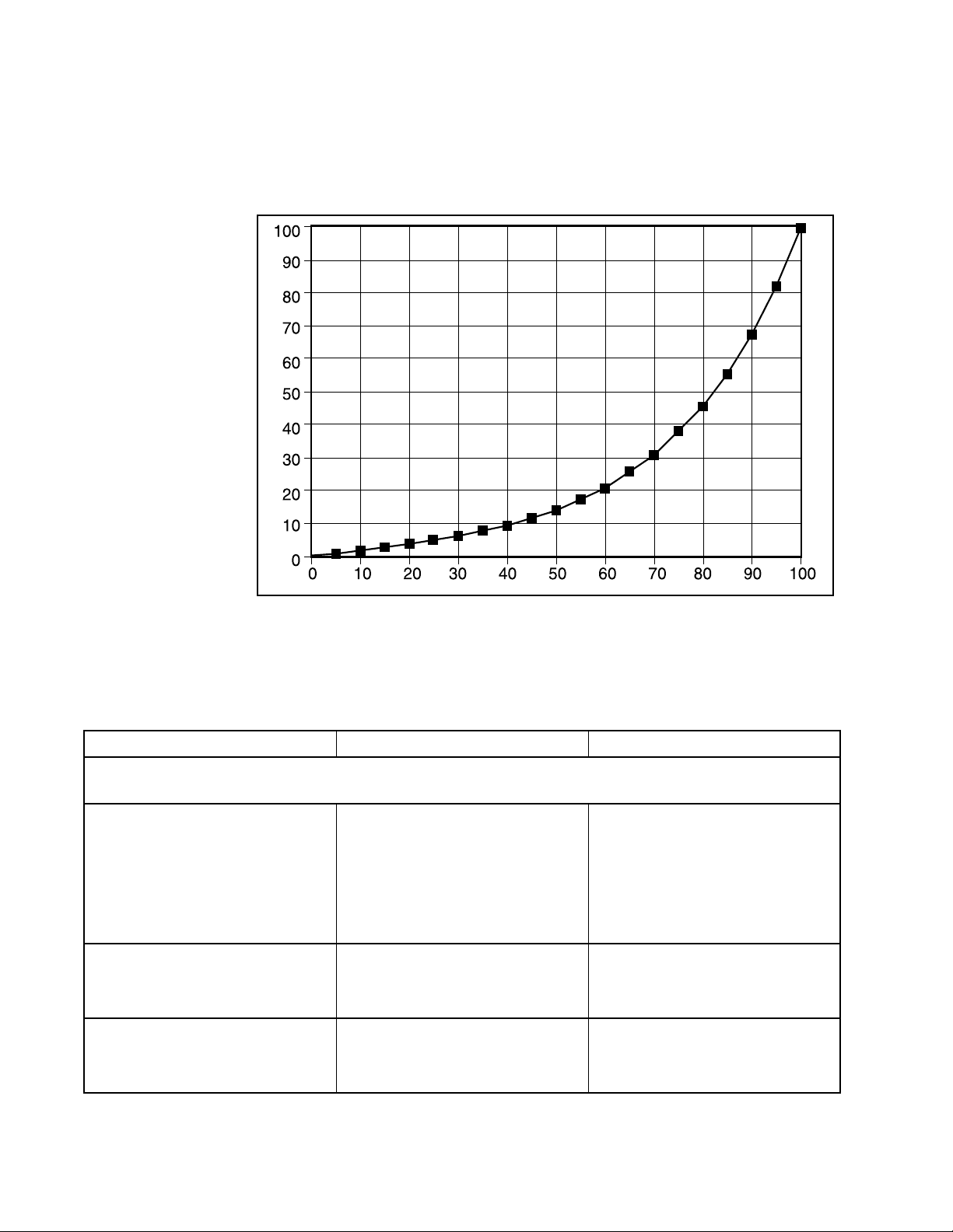
.
%
Command
00.00
51.00
10 2.00
15 3.00
20 4.00
25 5.24
30 6.47
35 8.02
40 9.57
45 11.86
50 14.15
55 17.54
60 20.93
65 25.94
70 30.95
75 38.36
80 45.77
85 55.66
90 67.68
95 82.31
100 100.00
% Control
Command
Table III: Equal Percentage Curve Data
NOTE: Custom characterization points can only be
entered by using ValTalk or SoftTools software. The
HART 275 handheld communicator wil l only allow the
Table IV: Troubleshooting Logix 1200 Digital Positioner (1 of 3)
Failure or Problem Probable Cause(s) Refer to Section(s)
Mounting and Installation
LED does not blink
1. 4-20 mA input polarity may be
reversed
1. 4-20 mA input level may be too
low
1. Calibration is in process
V alve moves in wrong dire cti on wi th no
input signal
1. Actuator is tubed for wrong air
action
1. Spool is stuck
Unit does not respond to analog 4-20
mA command
1. Unit is in digital command mode
1. Error occu rred during calibration
user to enable or di sable the currently sto red custom
characterization.
1. See
Electrical Wiring
on
page 44-31. or Wiring and
Grounding guidelines on page
44-6.
1. See overview on page 44-4.
1. See
1. See
1. See
1. See
Calibration
Air Action
Spool Valv e
Theory of Operation
on page 44-33..
on page 44-32.
on page 44-35.
on
page 44-30.
1. See
Calibration
on page 44-33.
Flowserve Corporation, Valtek Control Products, Tel. USA 801 489 8611 44-41
Page 42

Failure or Problem Probable Cause(s) Refer to Section(s)
Calibration
Table IV: Troubleshooting Logix 1200 Digital Positioner (2 of 3)
Red LED blinks after a Quick-Cal operation. Valve stays in fully open or
closed position.
Yellow LED blinks after a Quick-Cal
operation
Rotary valve has a dead band at the
fully open or closed pos ition
Red LED after loop current calibration
Control and Tuning
Valve will not saturate at closed position
Valve will not travel below or above a
certain limit
Sticking or hunting operation of the
positioner
1. Positioner configured for Linear
operation, but mounted on a
rotary actuator
1. Feedback linkage out of range
1. Valve did not fully stroke during
calibration (low or no air supply)
1. Mechanical travel is not centered within the electrical measurement range.
1. Applied Current is greater than
21 mA
1. See
page 44-33.
1. See Stem Position Sensor on
page 44-12.
1. See
page 44-33. or 44-16.
1. See
page 44-32. or Stem Position
Sensor on page 44-12.
1. See
tion Flag
1. Current source changed
between two values
1. MPC may need to be enabled 1. See
Cutoff)
1. Soft limits not enabled
1. MPC not enabled
1. Contamination of spool valve
assembly
1. Incorrect adjustment of P+I setting
1. See
page 44-40.
1. See
on page 44-31. See
on page 44-35.
1. See
page 44-34.
Quick-Cal Function
Quick-Cal Function
Linear vs. Rotary
on
on
on
Command 100% Calibra-
on page 44-33.
MPC (Minimum Position
on page 44-38.
Advanced Features
on
Air Supply Requirements
Spool V alv e
Setting P+I Parameters
on
Large init ial deviation. O nly present on
initial power-up.
Stem position movement is not linear
with command
1. Inner loop offset not correct 1. See
page 44-34.
1. Custom character i za tion not
enabled
1. See
on page 44-40.
Setting P+I Parameters
Custom Characterization
on
HART Communication
Will not communicate
HART 275 communicator indicates
Generic after it connects to positioner
1. Current source problem; May
need HART filter
1. Modem connection not operating correctly
1. HART module not enabled in
ValTalk software
1. Handheld not programmed with
Valtek DD
1. See
1. See
Current Source Interfer-
on page 44-35.
ence
HART Modem
on
page 44-36.
1. In
Options
, select HART proto-
col
1. Contact Flowserve Flow Control Division's Houston facility at
281.479.9500.
44-42 Flowserve Corporation, Valtek Control Products, Tel. USA 801 489 8611
Page 43

Failure or Problem Probable Cause(s) Refer to Section(s)
Erratic communications
Alarms
Table IV: Troubleshooting Logix 1200 Digital Positioner (3 of 3)
1. Maximum cable length or
impedance exceeded
1. See
page 44-35.
HART Communication
1. HART modem not receiving
enough power. (laptop batteries
low)
1. Interference with I.S. barrier
on
Temperature
Hall sensor
Modulator Current
EEPROM checksum
Multiple Internal Flags
LEDs
LED alternates between Green and
Red in normal operation
No LED blinks during calibration
1. Ambient temperature has
1. See
exceeded electronics ratings
1. Cable may have bad connection
1. See
1. Sensor may be damaged
1. Modulator minimum pressure
1. See
may be too low
1. Clogged orifice
1. Bad cable connection
1. Error when reading non-volatile
1. See
memory storage
1. Bad micro-controller on main
1. Replace main PCB assembly
PCB assembly
1. Modulator coil current may be
1. See
too high
1. Supply pressure may be close
to minimum of 30 psig (2.1 barg)
1. Normal operation 1.
Temperature Alarm
page 44-37.
Hall Sensor Alarm
page 44-37.
Modulator Current Alarm
on page 44-37.
EEPROM Chec ksum Alarm
on page 44-38.
Modulator Current Alarm
on page 44-37.
on
on
Yellow LED is blinking but valve position is fine
1. User-defined limit may have
been reached; check alarm
1. See
on page 44-38.
Alerts
screen
Red LED is blinking on advanced
model, even though positioner has
pressure
1. Pressure below 30 psi (2.1 bar) 1. See
page 44-38.
Pressure Alarms
on
Advanced Features
Will not display pressure readings
MPC will not function
1. Configuration not set to
Advanced
1. Lower soft limit >= 0%.
1. 1% hysteresis around MPC set-
1. See
Diagnostics
1. See
Cutoff)
Standard vs. Advanced
on page 44-40.
MPC (Minimum Position
on page 44-38.
point being considered
Flowserve Corporation, Valtek Control Products, Tel. USA 801 489 8611 44-43
Page 44

44-44 Flowserve Corporation, Valtek Control Products, Tel. USA 801 489 8611
Page 45

Flowserve Corporation has established industry leadership in the design and manufacture of its products. When properly selected, this Flowserve product is designed to perform its intended
function safely during its useful life. However, the purchaser or user of Flowserve products should be aware that Flowserve products might be used in numerous applications under a wide variety of industrial service conditions. Although Flowserve can (and often does) provide general guidelines, it cannot provide specific data and warnings for all possible applications. The purchaser/user must therefore assume the ultimate responsibility for the proper sizing and selection, installation, operation and maintenance of Flowserve products. The purchaser/user should
read and understand the Installation Operation Maintenance (IOM) instructions included with the product, and train its employees and contractors in the safe use of Flowser ve products in connection with the specific application.
While the information and specifications presented in this literature are believed to be accurate, they are supplied for informative purposes only and should not be considered certified or as a
guarantee of satisfacto ry results by r eli ance th ereo n. Nothing contai ne d here in is to be con s trued as a w arr a nty or g uar ant ee , express or implied, regarding any matter with respect to this prod uct. Because Flowserve is continu al ly impr o ving and upgrading its product design, the specifications, dimensio ns and information contained herein are sub ject to cha nge w itho ut not ice . Shoul d
any question arise concerning these provisions, the purchaser/user should contact Flowserve Corporation at any of its worldwide operations or offices.
For more information, contact:
For more information about Flowserve and its pr oducts,
contact www.flowserve.com or call USA 972 443 6500
Manufacturing Facilities
1350 N. Mt. Springs Prkwy.
Springville, UT 84663
Telephone 801 489 8611
Facsimile 801 489 3719
1300 Parkway V iew Drive
Pittsburgh, PA 15205 USA
Telephone 412 787 8803
Facsimile 412 787 1944
Manderscheidstr. 19
45141 Essen, Germany
Telephone (49) 2 01 89 19 5
Facsimile (49) 2 01 891 9600
Alläe du Quartz 1
CH-2300 La Chaux-de-Fonds
Switzerland
Telephone (41) 32 925 9700
Facsimile (41) 32 926 5422
Quick Response Centers
5114 Railroad Street
Deer Park, TX 77536 USA
Telephone 281 479 9500
Facsimile 281 479 8511
104 Chelsea Parkway
Boothwyn, PA 19061 USA
Telephone 610 497 8600
Facsimile 610 497 6680
FCD VLAIM044-04c© 2000 Flowserve Corporation. Flowserve Corporation, Valtek Control Products, Tel. USA 801 489 8611
 Loading...