

Page 1

®
Pump Division
Type: LNGT
CENTRIFUGAL PUMP
USER INSTRUCTIONS:
INSTALLATION, OPERATION, MAINTENANCE
PCN=00083107 02-08 [E]
These instructions must be read prior to installing,
operating, using and maintaining this equipment.
Page 2

LNGT USER INSTRUCTIONS ENGLISH 00083107 02-08
®
CONTENTS
Page
1 INTRODUCTION AND SAFETY ...........................4
1.1 General ........................................................... 4
1.2 CE marking and approvals..............................4
1.3 Disclaimer ....................................................... 4
1.4 Copyright......................................................... 4
1.5 Duty conditions ...............................................4
1.6 Safety..............................................................5
1.7 Nameplate and warning labels........................8
1.8 Specific machine performance........................9
1.9 Noise level.......................................................9
2. TRANSPORT AND STORAGE...........................11
2.1 Consignment receipt and unpacking ............11
2.2 Handling........................................................11
2.3 Lifting.............................................................11
2.4 Storage..........................................................12
2.5 Recycling and scrapping at the end of product
life..................................................................
3 PUMP DESCRIPTION.........................................12
3.1 Configurations and Specific feature..............12
3.2 Name nomenclature......................................13
3.3 Design of major parts....................................14
3.4 Performance and operating limits................. 14
12
6.9 Assembly.......................................................33
7 FAULTS; CAUSES AND REMEDIES...................37
8 PARTS LISTS AND DRAWINGS.........................40
8.1 LNGT – grease lubricated, packed gland
[single or double volute].................................
40
8.2 LNGT – oil lubricated, packed gland [single or
double volute].................................................
42
8.3 LNGT – Stuffing box.......................................44
8.4 General Arrangement Drawing......................45
9 CERTIFICATION..................................................45
10 OTHER RELEVANT DOCUMENTATION AND
MANUALS ........................................................
45
10.1 Supplementary User Instructions ................45
10.2 Change notes..............................................45
10.3 Additional sources of information ................45
4 INSTALLATION....................................................16
4.1 Location.........................................................16
4.2 Foundation.................................................... 16
4.3 Initial alignment............................................. 17
4.4 Piping............................................................18
4.5 Final shaft alignment check .......................... 23
4.6 Electrical connections...................................23
4.7 Protection systems........................................ 24
5 COMMISSIONING, START-UP, OPERATION AND
SHUTDOWN....................................................
24
5.1 Pre-commissioning procedure......................24
5.2 Pump lubricants............................................25
5.3 Direction of rotation.......................................25
5.4 Guarding ....................................................... 25
5.5 Priming and auxiliary supplies ...................... 25
5.6 Starting the pump..........................................26
5.7 Running the pump.........................................26
5.8 Stopping and shutdown.................................28
5.9 Hydraulic, mechanical and electrical duty.....28
6 MAINTENANCE...................................................28
6.1 General ......................................................... 28
6.2 Maintenance schedule..................................29
6.3 Spare p art s....................................................30
6.4 Recommended spares and consumable items
.......................................................................
30
6.5 Tools required................................................31
6.6 Fastener torques...........................................31
6.7 Renewal clearances......................................31
6.8 Disassembly.................................................. 31
Page 2 of 48
Page 3

LNGT USER INSTRUCTIONS ENGLISH 00083107 02-08
®
INDEX
Page
Additional sources [10.3].........................................45
Alignment of shafting [see 4.3, 4.5 and 4.7]..17,23,24
Assembly [6.9].........................................................33
ATEX marking [1.6.4.2] .............................................7
CE marking and approvals [1.2]................................4
Certification [9]......................................................... 45
Change notes [10.2]................................................45
Clearances [see 6.7, Renewal clearances]............. 31
Commissioning and operation [5]............................24
Compliance, ATEX [1.6.4.1]......................................6
Configurations [3.1]..................................................12
Copyright [1.4] ........................................................... 4
Design of major parts [3.3] ......................................14
Direction of rotation [5.3] .........................................25
Disassembly [6.8] .................................................... 31
Disclaimer [1.3]..........................................................4
Dismantling [see 6.8, Disassembly].........................31
Drawings [8].............................................................40
Duty conditions [1.5]..................................................4
Electrical connections [4.6]......................................24
End of product life [2.5]............................................ 12
Fastener torques [6.6] .............................................31
Faults; causes and remedies [7]..............................37
Foundation [4.2]....................................................... 16
Forces and moments [4.4.3.1 and 4.4.3.2]..............20
General arrangement drawing [8.4]......................... 45
Grouting [4.2.1]........................................................16
Guarding [5.4]..........................................................26
Handling [2.2]...........................................................11
Hydraulic, mechanical and electrical duty [5.9].......28
Impeller clearance [6.7] ...........................................26
Inspection [6.2.1 and 6.2.2].....................................29
Installation [4]...........................................................16
Lifting [2.3]...............................................................11
Location [4.1]...........................................................16
Lubrication [see 5.1.1, 5.2 and 6.2.3].................25,30
Maintenance [6].......................................................28
Maintenance schedule [6.2].....................................29
Name nomenclature [3.2] ........................................ 13
Nameplate [1.7.1] ...................................................... 8
Operating limits [3.4.1]............................................. 14
Ordering spare parts [6.3.1].....................................30
Parts lists [8]............................................................40
Performance [3.4]....................................................14
Piping [4.4]...............................................................18
Pre-commissioning [5.1].......................................... 25
Protection systems [4.7] ..........................................24
Pump and impeller data [3.4.2]................................15
Page
Reassembly [see 6.9 Assembly]..............................33
Receipt and unpacking [2.1].....................................11
Recommended fill quantities [see 5.2.1]..................25
Recommended grease lubricants [5.2.2.2] ..............25
Recommended spares [6.4].....................................30
Recycling [2.5]..........................................................12
Replacement parts [see 6.3 and 6.4].......................30
Running the pump [5.7]............................................26
Safety action [1.6.3]....................................................5
Safety markings [1.6.1] ..............................................5
Safety, protection system [see 1.6 and 4.7]......... 5,24
Sectional drawings [8]..............................................40
Sound level [see 1.9, Noise level]..............................9
Sources, additional information [10.3]......................45
Spare parts [6.3].......................................................30
Specific machine performance [1.8]...........................9
Starting the pump [5.6].............................................26
Stop/start frequency [5.7.6]......................................27
Stopping and shutdown [5.8]....................................28
Storage, pump [2.4]..................................................12
Storage, spare parts [6.3.2]......................................30
Supplementary manuals or information sources [10]
..................................................................................45
Tools required [6.5] ..................................................31
Torques for fasteners [6.6].......................................31
Trouble-shooting [see 7] ..........................................37
Vibration [5.7.5]........................................................27
Warning labels [1.7.2] ................................................8
Page 3 of 48
Page 4
LNGT USER INSTRUCTIONS ENGLISH 00083107 02-08
®
1 INTRODUCTION AND SAFETY
1.1 General
These instructions must always be kept
close to the product's operating location or
directly with the product.
Flowserve products are designed, developed and
manufactured with state-of-the-art technologies in
modern facilities. The unit is produced with great
care and commitment to continuous quality control,
utilizing sophisticated quality techniques, and safety
requirements.
Flowserve is committed to continuous quality
improvement and being at service for any further
information about the product in its installation and
operation or about its support products, repair and
diagnostic services.
These instructions are intended to facilitate
familiarization with the product and its permitted use.
Operating the product in compliance with these
instructions is important to help ensure reliability in
service and avoid risks. The instructions may not
take into account local regulations; ensure such
regulations are observed by all, including those
installing the product. Always coordinate repair
activity with operations personnel, and follow all plant
safety requirements and applicable safety and health
laws and regulations.
These instructions should be read prior to
installing, operating, using and maintaining the
equipment in any region worldwide. The
equipment must not be put into service until all
the conditions relating to safety noted in the
instructions, have been met.
1.2 CE marking and approvals
It is a legal requirement that machinery and
equipment put into service within certain regions of
the world shall conform with the applicable CE
Marking Directives covering Machinery and, where
applicable, Low Voltage Equipment, Electromagnetic
Compatibility [EMC], Pressure Equipment Directive
[PED] and Equipment for Potentially Explosive
Atmospheres [ATEX].
Where applicable the Directives and any additional
Approvals cover important safety aspects relating to
machinery and equipment and the satisfactory provision
of technical documents and safety instructions. Where
applicable this document incorporates information
relevant to these Directives and App rovals.
To confirm the Approvals applying and if the product is
CE marked, check the serial number plate markings
and the Certification. [See secti on 9, Certif ication.]
1.3 Disclaimer
Information in these User Instructions is believed to
be reliable. In spite of all the efforts of Flowserve
Pump Division to provide sound a nd all ne cessar y
information the content of this manual may appear
insufficient and is not guaranteed by Flowserve as
to its completeness or accuracy.
Flowserve manufactures products to exacting
International Quality Management System Standards as
certified and audited by external Quality Assurance
organizations. Genuine parts and accessories have
been designed, tested and incorporated into the
products to help ensure their continued product quality
and performance in use. As Flowserve cannot test
parts and accessories sourced fr om other vendo rs the
incorrect incorporation of such parts and accessories
may adversely affect the performance and safety
features of the products. The failure to properly select,
install or use authorized Flow serve parts an d
accessories is considered to be misuse. Damage or
failure caused by misuse is not cov ered by the
Flowserve warranty. In addition, any modification of
Flowserve products or removal of original components
may impair the safety of these products in their use.
1.4 Copyright
All rights reserved. No part of these instructions may
be reproduced, stored in a retrieval system or
transmitted in any form or by any means without prior
permission of Flowserve Pump Division.
1.5 Duty conditions
This product has been selected to meet the
specifications of your purchaser order. The
acknowledgement of these conditions has been sent
separately to the Purchaser. A copy should be kept
with these instructions.
The product must not be operated beyond
the parameters specified for the application. If
there is any doubt as to the suitability of the
product for the application intended, contact
Flowserve for advice, quoting the serial number.
If the conditions of service on your purchase order
are going to be changed [for example liquid pumped,
temperature or duty] it is requested that the user
seeks the written agreement of Flowserve before
start up.
Page 4 of 48
Page 5

LNGT USER INSTRUCTIONS ENGLISH 00083107 02-08
®
1.6 Safety
1.6.1 Summary of safety markings
These User Instructions contain specific safety
markings where non-observance of an instruction would
cause hazards. The specific safety markings are:
This symbol indicates electrical safety
instructions where non-compliance will involve a high
risk to personal safety or the loss of life.
This symbol indicates safety instruct ions where
non-compliance would affect personal safety and
could result in loss of life.
This symbol indicates “hazardous and toxic fluid”
safety instructions where non-compliance would affect
personal safety and could result in loss of life.
This symbol indicates safety
instructions where non-compliance will involve some
risk to safe operation and personal safety and would
damage the equipment or property.
This symbol indicates explosive atmosphere
zone marking according to ATEX. It is used in safety
instructions where non-compliance in the hazardous
area would cause the risk of an explosion.
1.6.3 Safety action
This is a summary of conditions and actions to
prevent injury to personnel and damage to the
environment and to equipment. For products
used in potentially explosive atmospheres
section 1.6.4 also applies.
NEVER DO MAINTENANCE WORK
WHEN THE UNIT IS CONNECTED TO POWER
GUARDS MUST NOT BE REMOVED WHILE
THE PUMP IS OPERATIONAL
DRAIN THE PUMP AND ISOLATE PIPEWORK
BEFORE DISMANTLING THE PUMP
The appropriate safety precautions should be taken
where the pumped liquids are hazardous.
HANDLING COMPONENTS
Many precision parts have sharp corners and the
wearing of appropriate safety gloves and equipment
is required when handling these components. To lift
heavy pieces above 25 kg [55 lb] use a crane
appropriate for the mass and in accordance with
current local regulations.
This symbol is used in safety instructions to
remind not to rub non-metallic surfaces with a dry
cloth; ensure the cloth is damp. It is used in safety
instructions where non-compliance in the hazardous
area would cause the risk of an explosion.
This sign is not a safety symbol but indicates
an important instructio n in the assembly pro cess.
Denotes the focussing of attention on the
importance of reading the instructions for use.
1.6.2 Personnel qualification and training
All personnel involved in the operation, installation,
inspection and maintenance of the unit must be
qualified to carry out the work involved. If the
personnel in question do not already possess the
necessary knowledge and skill, appropriate training
and instruction must be provided. If required the
operator may commission the manufacturer/supplier
to provide applicable training.
Always coordinate repair activity with operations and
health and safety personnel, and follow all plant
safety requirements and applicable safety and health
laws and regulations.
THERMAL SHOCK
Rapid changes in the temperature of the liquid within
the pump can cause thermal shock, which can result
in damage or breakage of components and should be
avoided.
NEVER APPLY HEAT TO REMOVE IMPELLER
Trapped lubricant or vapor could cause an explosion.
HOT [and cold] PARTS
If hot or freezing components or auxiliary heating
supplies can present a danger to operators and
persons entering the immediate area action must be
taken to avoid accidental contact. If complete
protection is not possible, the machine access must
be limited to maintenance staff only, with clear visual
warnings and indicators to those entering the
immediate area. Note: bearing housings must not be
insulated and drive motors and bearings may be hot.
If the temperature is greater than 68 °C [175 °F] or
below 5 °C [20 °F] in a restricted zone, or exceeds
local regulations, action as above shall be taken.
Page 5 of 48
Page 6

LNGT USER INSTRUCTIONS ENGLISH 00083107 02-08
®
1.6.4 Products used in potentially explosive
PREVENT EXCESSIVE EXTERNAL
atmospheres
PIPE LOAD
Do not use pump as a support for piping. Do not
mount expansion joints, unless allowed by Flowserve
in writing, so that their force, due to internal pressure,
acts on the pump flange.
ENSURE CORRECT LUBRICATION
[See section 5, Commissioning, start up, operation
and shutdown.]
START THE PUMP PREFERABLY
WITH OUTLET VALVE PARTLY OPENED
[Unless otherwise instructed at a specific point in the
Supplementary User Instructions.]
This is recommended to minimize the risk of
overloading and damaging the pump motor at full or
zero flow. Pumps may be started with the valve
further open only on installations where this situation
cannot occur. The pump outlet control valve may
need to be adjusted to comply with the duty following
the run-up process. [See section 5.6, Commissioning
start-up, operation and shutdown.]
NEVER RUN THE PUMP DRY
INLET VALVES TO BE FULLY OPEN
WHEN PUMP IS RUNNING
Running the pump at zero flow or below the
recommended minimum flow continuously will cause
damage to the seal.
DO NOT RUN THE PUMP AT
ABNORMALLY HIGH OR LOW FLOW RATES
Operating at a flow rate higher than norma l or at a flo w
rate with no back pressure on the pump may overload
the motor and cause cavitation. Low flow rates may
cause a reduction in pump/beari ng life, ov erheatin g of
the pump, instability and cavitation/vibrat ion.
Measures are required to:
• Avoid excess temperature
• Prevent build up of explosive mixtures
• Prevent the generation of sparks
• Prevent leakages
• Maintain the pump to avoid hazard
The following instru ctions fo r pumps a nd pum p units
when installed in potentially explosive atmospheres
must be followed to help ensure explosion protecti on.
Both electrical and non-electri cal equi pment mu st meet
the requirements of European Directive 94/9/EC.
1.6.4.1 Scope of compliance
Use equipment only in the zone for whic h it is
appropriate. Always check that the driver, drive
coupling assembly, seal and pump equipment are
suitably rated and/or certifie d for the classi fication of the
specific atmosphere in which they are to be inst alled.
Where Flowserve has supplied only the bare shaft
pump, the Ex rating applies only to the pump. The
party responsible for assembling the pump set shall
select the coupling, driver and any additional
equipment, with the necessary CE Certificate/
Declaration of Conformity establishing it is suitable for
the area in which it is to be installed.
The output from a variable frequency drive [VFD] can
cause additional heating aff ects i n the moto r and so, fo r
pumps sets with a VFD, the ATEX Certification for the
motor must state that it is covers th e situa tion where
electrical supply is from the VFD. This particular
requirement still applies even if the VFD is in a safe
area.
Page 6 of 48
Page 7
LNGT USER INSTRUCTIONS ENGLISH 00083107 02-08
®
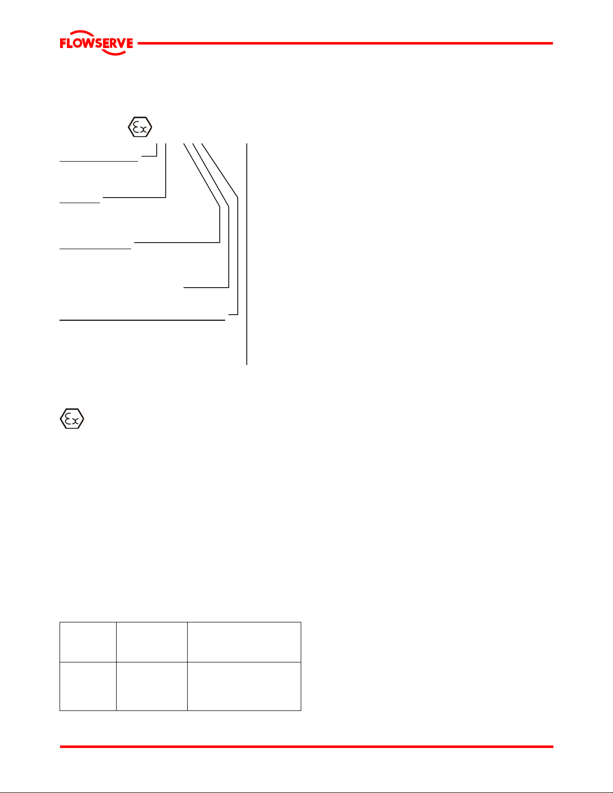
1.6.4.2 Marking
An example of ATEX equipment marking is shown
below. The actual classification of the pump will be
engraved on the nameplate.
II 2 GD c IIC 135 ºC [T4]
Equipment Group
I = Mining
II = Non-mining
Category
2 or M2 = high level protection
3 = normal level of protection
Gas and/or dust
G = Gas
D = Dust
c = Constructional safety
[in accordance with EN13463-5]
Gas Group [Equipment Category 2 only]
IIA – Prop ane [typical]
IIB – Ethylene [typical]
IIC – Hydrogen [typical]
Maximum surface temperature [Temperature Class]
[See section 1.6.4.3.]
1.6.4.3 Avoiding excessive surface temperatures
ENSURE THE EQUIPMENT TEMPERATURE
CLASS IS SUITABLE FOR THE HAZARD ZONE
Pumps have a temperature class as stated in the
ATEX Ex rating on the nameplate. These are based
on a maximum ambient of 40 °C [104 °F]; refer to
Flowserve for higher ambient temperatures.
The surface temperature on the pump is influenced
by the temperature of the liquid handled. The
maximum permissible liquid temperature depends on
the temperature class and must not exceed the
values in the table that follows.
The temperature rise at the seals and bearings and
due to the minimum permitted flow rate is taken into
account in the temperatures stated.
Temperature
class to
EN13463-1
T6
T5
T4
T3
Maximum
surface
temperature
permitted
85 °C [185 °F]
100 °C [212 °F]
135 °C [275 °F]
200 °C [392 °F]
Temperature limit of liquid
handled [* depending on
material and construction
variant - check which is lower]
Consult Flowserve
Consult Flowserve
115 °C [239 °F] *
180 °C [356 °F] *
The responsibility for compliance with the
specified maximum liquid temperature is with the
plant operator.
Temperature classification “Tx” is used when the
liquid temperature varies and the pump could be
installed in different hazardous atmospheres. In this
case the user is responsible for ensuring that the
pump surface temperature does not exceed that
permitted in the particular hazardous atmosphere.
If an explosive atmosphere exists during the
installation, do not attempt to check the direction of
rotation by starting the pump unfilled. Even a short
run time may give a high temperature resulting from
contact between rotating and stationary components.
Where there is any risk of the pump being run against a
closed valve generating high liqui d and casing extern al
surface temperatures it is recommended that users fit
an external surface temperature protectio n device.
Avoid mechanical, hydraulic or electrical overload by
using motor overload trips, temperature monitor or a
power monitor and make routine vibration monitoring
checks.
In dirty or dusty environments, regular checks must
be made and dirt removed from areas around close
clearances, bearing housings and motors.
Page 7 of 48
Page 8
LNGT USER INSTRUCTIONS ENGLISH 00083107 02-08
®
1.6.4.4 Preventing sparks
To prevent a potential hazard from mechanical
contact, the coupling guard must be non-sparking.
To avoid the potential hazard from random induced
current generating a spark, the earth contact on the
baseplate must be used.
Avoid electrostatic charge: do not rub nonmetallic surfaces with a dry cloth; ensure cloth is
damp.
The coupling must be selected to comply with 94/9/EC
and correct alignment must be maintained.
1.6.4.5 Preventing leakage
The pump must only be used to handle liquids
for which it has been approved to have the correct
corrosion resistance.
Avoid entrapment of liquid in the pump a nd associat ed
piping due to closing of suct ion an d discharg e valves,
which could cause dangerous excessiv e pressures to
occur if there is heat input to the liquid. This can occur if
the pump is stationary or running.
Bursting of liquid containing parts due to freezing
must be avoided by draining or protecting the pump
and ancillary systems.
Where there is the potential hazard of a loss of a seal
barrier fluid or external flush, the fluid must be
monitored.
If leakage of liquid to atmosphere can result in a
hazard, the installation of a liquid detection device is
recommended.
1.6.4.6 Maintenance to avoid the hazard
It is recommended that a maintenance plan and
schedule is adopted. [See section 6, Maintenance.]
1.7 Nameplate and warning labels
1.7.1 Nameplate
Every pump has a name plate made in stainless steel
with information regarding operating condition as
capacity, total dynamic head, rotational speed,
specific gravity and serial number. For details of
nameplate, see the Declaration of Conformity.
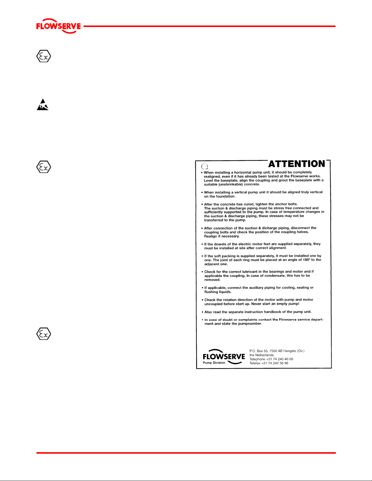
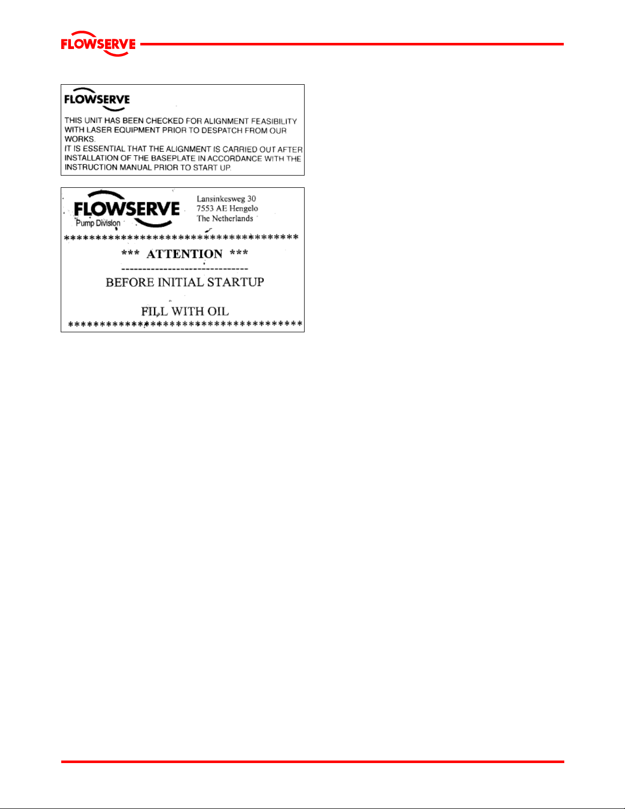
1.7.2 Warning labels
The pump has been shipped with 1 or more warning
labels. Follow the instructions on these labels
carefully.
CORRECT MAINTENANCE IS REQUIRED TO
AVOID POTENTIAL HAZARDS WHICH GIVE A
RISK OF EXPLOSION
The responsibility for compliance with maintenance
instructions is with the plant operator.
To avoid potential explosion hazards during
maintenance, the tools, cleaning and painting
materials used must not give rise to sparking or
adversely affect the ambient conditions. Where there
is a risk from such tools or materials, maintenance
must be conducted in a safe area.
Page 8 of 48
Page 9
LNGT USER INSTRUCTIONS ENGLISH 00083107 02-08
®
1.8 Specific machine performance
For performance parameters see section 1.5, Duty
conditions. When the contract requirement specifies
these to be incorporated into User Instructions these
are included in the Supplementary User Instructions.
Where performance data has been supplied
separately to the purchaser these should be obtained
and retained with these User Instructions if required.
1.9 Noise level
When pump noise level exceeds 85 dBA attention
must be given to prevailing Health and Safety
Legislation, to limit the exposure of plant operating
personnel to the noise. The usual approach is to
control exposure time to the noise or to enclose the
machine to reduce emitted sound. You may have
already specified a limiting noise level when the
equipment was ordered, however if no noise
requirements were defined then machines above a
certain power level will exceed 85 dBA. In such
situations consideration must be given to the fitting of
an acoustic enclosure to meet local regulations.
Pump noise level is dependent on a number of
factors - the type of motor fitted, the operating
capacity, pipe work design and acoustic
characteristics of the building.
Typical sound pressure levels measured in dB
and A-weighted are shown in the table below the
figures are indicative only, they are subject to a
+3 dB tolerance, and cannot be guaranteed.
The values are based on the noisiest ungeared
electric motors that are likely to be encountered.
They represent sound pressure levels at 1 m [3.3 ft]
from the directly driven pump, for "free field over a
reflecting plane".
If a pump unit only has been purchased, for fitting
with your own driver, then the "pump only" noise
levels from the table should be combined with the
level for the driver obtained from the supplier. If the
motor is driven by an inverter, it may show an
increase in noise level at some speeds. Consult a
Noise Specialist for the combined calculation.
For units driven by equipment other than electric
motors or units contained within enclosures, see the
accompanying information sheets and manuals.
Page 9 of 48
Page 10

Typical sound pressure level, dBA, L
and speed
kW [hp]
<0.55 [<0.75] 71 [88] 66 [83] 64 [81] 62 [79] 64 [81] 62 [79] 63 [80] 62 [79]
0.75 [1] 74 [91] 66 [83] 67 [84] 62 [79] 67 [84] 62 [79] 63 [80] 62 [79]
1.1 [1.5] 74 [91] 68 [85] 67 [84] 64 [81] 67 [84] 64 [81] 65 [82] 64 [81]
1.5 [2] 77 [94] 70 [87] 70 [87] 66 [83] 70 [87] 66 [83] 66 [83] 66 [83]
2.2 [3] 78 [95] 72 [89] 71 [88] 68 [85] 71 [88] 68 [85] 68 [85] 68 [85]
3 [4] 81 [98] 74 [91] 74 [91] 70 [87] 74 [91] 70 [87] 70 [87] 70 [87]
4 [5] 82 [99] 75 [92] 75 [92] 71 [88] 75 [92] 71 [88] 71 [88] 71 [88]
5.5 [7.5] 90 [107] 77 [94] 83 [100] 73 [90] 76 [93] 73 [90] 72 [89] 71 [88]
7.5 [10] 90 [107] 78 [95] 83 [100] 74 [91] 77 [94] 74 [91] 73 [90] 72 [89]
11 [15] 91 [108] 80 [97] 84 [101] 76 [93] 78 [95] 76 [93] 74 [91] 73 [90]
15 [20] 92 [109] 83 [100] 85 [102] 79 [96] 80 [97] 79 [96] 76 [93] 75 [92]
18.5 [25] 92 [109] 83 [100] 85 [102] 79 [96] 80 [97] 79 [96] 76 [93] 75 [92]
22 [30] 92 [109] 83 [100] 85 [102] 79 [96] 81 [98] 79 [96] 77 [94] 75 [92]
30 [40] 100 [117] 85 [102] 93 [110] 81 [98] 84 [101] 80 [97] 80 [97] 76 [93]
37 [50] 100 [117] 86 [103] 93 [110] 82 [99] 84 [101] 80 [97] 80 [97] 76 [93]
45 [60] 100 [117] 87 [104] 93 [110] 83 [100] 84 [101] 80 [97] 80 [97] 76 [93]
55 [75] 100 [117] 88 [105] 95 [112] 84 [101] 86 [103] 81 [98] 82 [99] 77 [94]
75 [100] 100 [117] 90 [107] 95 [112] 86 [103] 88 [105] 81 [98] 83 [100] 78 [95]
90 [120] 100 [117] 90 [107] 95 [112] 86 [103] 90 [107] 81 [98] 85 [102] 78 [95]
110 [150] 100 [117] 91 [108] 95 [112] 87 [104] 91 [108] 83 [100] 86 [103] 79 [96]
150 [200] 101 [118] 92 [109] 96 [113] 88 [105] 91 [108] 83 [100] 86 [103] 79 [96]
200 [270] [1] [1] [1] [1] [1] 83 [100] [1] 80 [97]
300 [400] - - - - [1] 84 [101] [1] 81 [98]
500 [670] - - - - [1] 85 [102] [1] 83 [100]
1000 [1300] - - - - [1] 86 [103] [1] 86 [103]
1500 [2000] - - - - [1] 90 [107] [1] 88 [105]
3550 r/min 2900 r/min 1750 r/min 1450 r/min Motor size
Pump and
motor
dB[A]
at 1 m reference 20 μPa [LwA sound power 1 pW where LpA >85 dBA]
pA
Pump
only
dB[A]
Pump and
motor
dB[A]
Pump
only
dB[A]
Pump and
motor
dB[A]
Pump
only
dB[A]
Pump and
motor
dB[A]
[1] Motors in this range are generally job specific and noise levels should be calculated based on actual
equipment installed. For 960 r/min reduce 1450 r/min values by 5 dBA
Pump
only
dB[A]
Page 11

LNGT USER INSTRUCTIONS ENGLISH 00083107 02-08
®
2. TRANSPORT AND STORAGE
2.1 Consignment receipt and unpacking
Immediately after receipt of the equipment it must
be checked against the delivery and shipping
documents for its completeness and that there
has been no damage in transportation.
Any shortage and or damage must be reported
immediately to Flowserve Pump Division and
received in writing within one month of receipt of
the equipment. Later claims cannot be accepted.
Check any crate, boxes and wrappings for any
accessories or spare parts that may be packed
separately with the equipment or attached to side
walls of the box or equipment.
Each product has a unique serial number. Check
that this number corresponds with that advised
and always quote this number in correspondence
as well as when ordering spare parts or further
accessories.
2.2 Handling
Boxes, crates, pallets or cartons may be
unloaded using fork-lift vehicles or slings
dependent on their size and construction.
2.3 Lifting
Fully trained personnel must carry out lifting,
in accordance with local regulations. The driver
and pump weights are recorded on their
respective General Arrangement Drawing.
should be lifted as shown. Unless otherwise
specified in the supplementary instructions.
Lift the centrifugal pump by attaching the lifting
cables around that part of the pump casing to
which the bearing pedestals are attached. To
prevent the pump unit from being damaged, use
a spreader.
2.3.1 Lifting the upper half of the pump
Lift the upper half of the pump casing using the
lifting lugs [or holes] attached to this half.
To avoid distortion, the pump unit
casing
A crane must be used for all pump sets,
components and accessories in excess of 25 kg
[55 lb]. Fully trained personnel must carry out
lifting, in accordance with local regulations. The
driver and pump weights are recorded on their
respective nameplates.
The pump is fitted with auxiliary
piping. Remove this piping before the pump is
lifted to avoid damage to these pipes and even
the pump. After erection of the pumps this piping
can be re-assembled easily. With every lifting
operation this procedure has to be repeated.
Unsafe lifting is never allowed!
Page 11 of 48
Page 12

LNGT USER INSTRUCTIONS ENGLISH 00083107 02-08
®
2.3.2 Lifting with foundation frame
[If applicable]
Lifting lugs have been welded to the
foundation frame for lifting purposes. The unit
should be hoisted using these lifting lugs.To
prevent the electric motor and/or pipe lines
from being damaged, use a spreader.
The pump should not be lifted as
shown:
Bare shaft pump:
Complete pump unit:
The driver and pump weight is recorded on their
respective nameplates. The total weight is
mentioned on the General Arrangement Drawing.
2.4 Storage
Store the pump in a clean , dry
location away from vibration. Leave piping
connection covers in place to keep dirt and other
foreign material out of pump casing. Turn pump
at intervals to prevent brinelling of the bearings
and the seal faces, if fitted, from sticking.
The pump may be stored as above for up to 6
months. Consult Flowserve for preservative
actions when a longer storage period is needed.
2.5 Recycling and scrapping at the end of product life
At the end of the service life of the product or its
parts, the relevant materials and parts should be
recycled or disposed of using an environmentally
acceptable method and local regulations. If the
product contains substances that are harmful to
the environment, these should be removed and
disposed of in accordance with current
regulations. This also includes the liquids and or
gases that may be used in the "seal system" or
other utilities.
Make sure that hazardous substances are
disposed of safely and that the correct personal
protective equipment is used. The safety
specifications must be in accordance with the
current regulations at all times.
3 PUMP DESCRIPTION
3.1 Configurations and Specific feature
3.1.1 Configurations
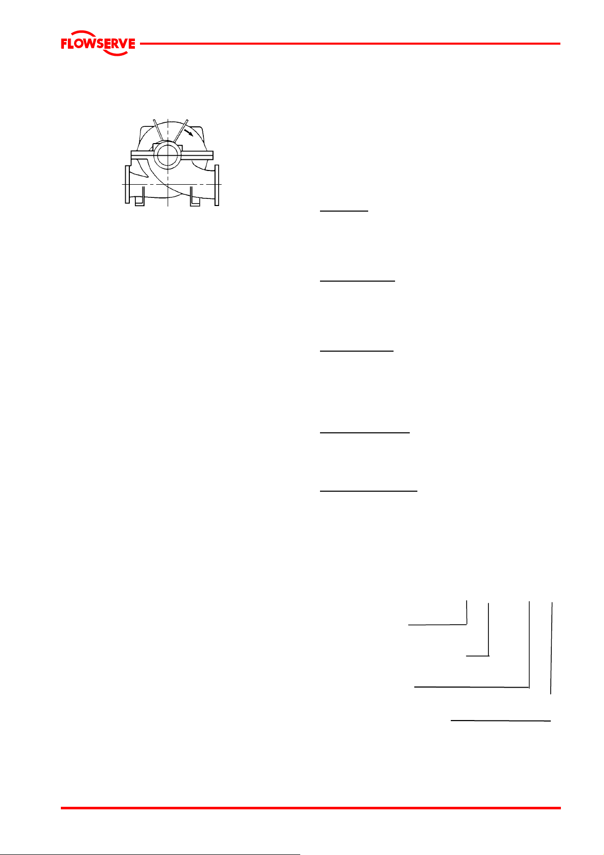
The LNGT type pump is a single stage, double
suction, horizontal split volute type centrifugal
pump designed for water transport and cooling
duties in industrial and potable water systems,
power stations, irrigation and drainage pumping
stations, fire fighting and marine systems, in
refineries and in petro-chemical and chemical
plants.
It can be used with motor, steam turbine and
gasoline or diesel engine drives.
LNGT pumps are used for the following reasons:
- High efficiency
- Low NPSH requirements
- Pump shaft carried in two bearings one on
either side.
- Quick and easy inspection of internals.
Page 12 of 48
Page 13
LNGT USER INSTRUCTIONS ENGLISH 00083107 02-08
®
The pumps feature a double volute, but some
small sizes have a single volute.
The LNGT has the following configuration:
LNGT horizontal suction and discharge nozzles [inline]
3.1.2 Specific features
The pump casing is axially split. The suction and
delivery nozzles are integral with the pump
casing bottom half and they are in line regarding
the horizontal centerline.
The two pump casing halves are assembled by
means of studs and nuts. Dismantling the pump
casing upper half allows quick inspection of the
pump internals, without it being necessary to
disturb the suction and delivery piping.
The rotor assembly can be easily removed.
Removal of pump casing and bearing housing
upper halves. If necessary use the jack screws.
Removal rotor assembly is now possible.
Reassembling of upper halves by means of
dowel pins. No realignment is needed.
The stuffing box chambers are part of the pump
casing.
In standard configuration, the pump has gland
packing rings with a lantern ring. Local to the
lantern rings, the stuffing box chambers have a
connection for flushing, in case needed. Single
mechanical seals are also available.
The space between pump casing and bearing
housing is designed in such a way, that the
packing rings can be replaced without it being
necessary to dismantle the pump. With various
pump sizes, the casing is of the double-volute
type in order to reduce radial force on the
impeller and consequently the shaft deflection.
The pump shaft is supported on either side of the
impeller by roller bearings or journal bearings
situated outside the pump casing. The bearings
are grease lubricated. Re-lubrication is possible
through the grease nipple in the bearing cover.
All pump sizes can also be provided with oil-bath
lubricated bearings. The bearing housings are
standard sealed with a V-ring (Labyrinth ring)
together with a retaining and/or thrower.
Bearing isolators are optional.
Sleeves local to the stuffing boxes protect the
pump shaft from effects of the pumped medium
and from wear local to the packing rings. On
either side of the impeller, replaceable case wear
rings are fitted to protect the pump casing. It is
also possible to provide the impeller with impeller
wear rings. The impeller wear rings are locked
with set screws to prevent co-rotation. The casing
wear rings are locked with dowel pin in the lower
half casing to prevent co-rotation.
Efficiency
The impeller and pump casings were designed,
using advanced techniques and extensive model
testing, which ensures optimum efficiency, thus
reducing the energy consumption.
Inlet conditions
Optimum design of the double-suction impeller
and optimum, elaborate test base, shaping of the
suction boxes provide the possibility of working at
low NPSH values.
Vibration/noise
The impeller is dynamically balanced, so the
pump amply satisfies maximum vibration levels
e.g. as demanded in standard VDI 2056. The
generously sized suction boxes also add to a low
noise level.
Interchange ability
The well-thought-out design ensures optimum
interchange ability of parts with those of other
sizes in the LNGT range.
Direction of rotation
The pumps are suited for both clockwise and
counter-clockwise rotation.
3.2 Name nomenclature
The pump size will be engraved on the
nameplate typically as below:
500-LNGT-800 Y1
Nominal discharge
branch size.
Configuration – see 3.1 above.
Nominal maximum
impeller diameter.
Hydraulic indentification for
impeller design
The typical nomenclature above is the general
guide to the LNGT configuration description.
Page 13 of 48
Page 14

LNGT USER INSTRUCTIONS ENGLISH 00083107 02-08
®
Identify the actual pump size and serial number
from the pump nameplate. Check that this
agrees with the applicable certification provided.
3.3 Design of major parts
Pump casing [1213 + 1214]
The pump has its main casing gasket axial to the
shaft allowing maintenance to the rotating
element by removing the upper half casing
[1213]. Suction and discharge branches are in
the bottom half [1214] and therefore remain
undisturbed.
Impeller [2200]
The double suction impeller is fully shrouded and
may be fitted with optional hub rings.
The impeller can be executed with staggered
vanes to minimize vibration.
Shaft [2100]
The large diameter stiff shaft, mounted on
bearings, has a keyed drive end.
Pump bearings and lubrication
Ball bearings (journal and thrust) are fitted as
standard and may be either oil or grease
lubricated, protected by V-ring (Labyrinth ring)
seals.
Bearing isolators or stationary labyrinths may be
fitted as an option in the bearing covers to protect
the bearings.
Bearing housing [3200]
Two grease n i pples enable grease lubricated
bearings to be replenished between major
service intervals. For oil lubricated bearings, a
constant level oiler is fitted.
Stuffing box [4110]
The stuffing box housing is designed for gland
packing rings. Mechanical seal is an option
Shaft seal [4010]
The mechanical seal[s] attached to the pump
shaft seals the pumped liquid from the
environment.
Gland packing may be fitted as an option.
Driver
The driver is normally an electric motor. Different
drive configurations may be fitted such as internal
combustion engines, turbines, hydraulic motors etc
driving via couplings, belts, gearboxes, drive shafts
etc.
Accessories
Accessories may be fitted when specified by the
customer.
3.4 Performance and operating limits
This product has been selected t o meet t he
specifications of your purchase order. See section
1.5.
The following data is included as additional
information to help with your installation. It is typical,
and factors such as temperature, materials, and seal
type may influence this data. If required, a definitive
statement for your particular application can be
obtained from Flowserve.
3.4.1 Operating limits
Pumped liquid temperature limits*
Maximum ambient temperature*
Maximum soft solids in
suspension*
Maximum pump speed
* Subject to written agreement from Flowserve.
- 20 to + 145 ºC*
[- 4 to + 176 ºF]
- 20 to + 40 ºC
[- 4 to +104 ºF]
up to 3 % by volume
[refer for size limits]
refer to the nameplate
Page 14 of 48
Page 15

LNGT USER INSTRUCTIONS ENGLISH 00083107 02-08
®
3.4.2 Pump and impeller data
Pump size
Impeller minimum
passage
size
mm [in.]
=
outlet width
150LNGT375F 17 [0.67]
150LNGT375G 24 [0.94]
150LNGT375H 26.4 [1.04]
150LNGT400F 22 [0.87]
150LNGT400G 19 [0.75]
150LNGT475F 18 [0.71]
200LNGT300F 27.5 [1.08]
200LNGT350F 18.3 [0.72]
200LNGT400F 19 [0.75]
200LNGT425F 23.4 [0.92]
200LNGT475F 26.6 [1.05]
200LNGT500F 18 [0.71]
200LNGT550F 20 [0.79]
200LNGT600F 20.6 [0.81]
250LNGT325F 30.6 [1.2]
250LNGT425F 23 [0.91]
250LNGT500F 35 [1.38]
250LNGT575F 30 [1.18]
250LNGT575G 32 [1.26]
250LNGT625F 34.8 [1.37]
300LNGT275F 41.3 [1.63]
300LNGT300F 62 [2.44]
300LNGT300G 49 [1.93]
300LNGT400F 33 [1.3]
300LNGT400G 37 [1.46]
300LNGT425F 34.8 [1.37]
300LNGT500F 26 [1.02]
300LNGT725F 26 [1.02]
350LNGT325F 74 [2.91]
350LNGT400F 58 [2.28]
350LNGT400G 61 [2.4]
350LNGT450F 39 [1.54]
350LNGT525F 33 [1.3]
350LNGT600F 28 [1.1]
350LNGT600G 40 [1.57]
350LNGT600H 34 [1.34]
350LNGT675F 44.5 [1.75]
400LNGT350F 90 [3.54]
400LNGT550F 43.5 [1.71]
500LNGT375F 85 [3.35]
500LNGT450F 78.3 [3.08]
500LNGT650F 35 [1.38]
800LNGT1250Y1 125 [4.92]
• note: 779/780 = DE / NDE
Nominal wear
ring diameter
mm
Case wear ring
only
210.4 230.4 0.2
210.4 230.4 0.2
190.35 210.35 0.175
190.35 210.35 0.175
210.4 230.4 0.2
190.35 210.35 0.175
210.4 230.4 0.2
210.4 230.4 0.2
230.45 250.45 0.225
210.4 230.4 0.2
230.45 250.45 0.225
210.4 230.4 0.2
230.45 250.45 0.225
240.45 260.45 0.225
230.45 250.45 0.225
255.45 275.45 0.225
270.45 290.45 0.225
270.45 290.45 0.225
270.45 290.45 0.225
285.45 305.45 0.225
255.45 275.45 0.225
240.45 260.45 0.225
210.4 240.45 0.2 / 0.225
270.45 290.45 0.225
250.45 270.45 0.225
300.5 320.5 0.25
285.45 305.45 0.225
295.45 315.45 0.225
300.5 320.5 0.25
300.5 320.5 0.25
300.5 320.5 0.25
300.5 320.5 0.25
340.5 360.5 0.25
340.5 360.5 0.25
340.5 360.5 0.25
290.45 335.45 0.225
375.5 395.5 0.25
300.5 320.5 0.25
375.5 395.5 0.25
340.5 360.5 0.25
340.5 360.5 0.25
375.5 395.5 0.25
- 779 / 780 0.6 / 0.6
Nominal wear
ring diameter
mm
Case- and
impeller wear
ring
Mean radial
wear ring clearance
mm
Approx. oil capacity,
both bearings
liter
Page 15 of 48
Page 16

LNGT USER INSTRUCTIONS ENGLISH 00083107 02-08
®
4 INSTALLATION
4.1 Location
The pump should be located to allow room for
access, ventilation, maintenance and inspection
with ample headroom for lifting and should be as
close as practicable to the supply of liquid to be
pumped.
Refer to the general arrangement drawing for the
pump set.
4.2 Foundation
bond between the grout of the foundation
bolts and the surface.
Remove the water from the recesses at the
time the foundation bolts are being grouted.
4.2.2 Positioning of the foundation bolts
Hoist the pump unit and position it above the
surface according to the lifting instructions.
Place the foundation bolts with nuts in the
foundation frame.
When positioning the pump unit, make
allowance for the following:
There are many methods of
installing pump units to their foundations. The
correct method depends on the size of the pump
unit, its location and noise vibration limitations.
Non-compliance with the provision of correct
foundation and installation may lead to failure of
the pump and, as such, would be outside the
terms of the warranty.
The surface onto which the pump unit is to be
placed should be of a material, which is
sufficiently hard and strong to provide a
permanent, non-flexible support to the entire
bearing surface of the pump unit.
The surface should also be smooth and level and
should be able to absorb normal vibrations and
loads the pump unit is subjected to during
operation. A concrete foundation is the most
suitable surface.
4.2.1 Grouting
Where applicable, grout in the foundation bolts.
See picture below for possible foundation bolt
types.
Prepare the recesses in the surface according to
following picture following the general
arrangement of the pump unit when doing so.
If the surface is concrete, follow the steps below:
Do not place the pump unit on the surface
until the surface is fully cured.
Fill the recesses with water at least 24 hours
before grouting the foundation bolts.
Moistening the recesses will ensure a better
The foundation bolts should be free to move
in the surface recesses.
The level of the centerline of the suction and
delivery connections should match the
centerline of the pipelines to be connected.
The position of the suction and delivery
connections for the X- and Z-axis
• The vertical distance between the surface
and the foundation frame [40 mm] to enable
grouting.
Put steel filler blocks on to the surface on both
sides of the foundation bolts
Place the pump unit on the filler blocks.
Adjust the pump unit so that it is roughly
horizontal and at the required level height
using [thin] shims between the steel filler
blocks and the foundation frame. In doing
this, the foundation frame should be
positioned so that the suction and delivery
flanges can be fitted to the pipe flanges free
of strain. Make sure that in doing so, the
flanges to be interconnected are parallel
within 0.1 mm of each other.
Check whether the bolts fit easily into the bolt
holes of the flanges. Fasten the foundation
bolts by filling the recesses using non-
Page 16 of 48
Page 17

LNGT USER INSTRUCTIONS ENGLISH 00083107 02-08
®
shrinking grout [for example Pagel V1 or
equivalent].
Leave the grout to cure according to the
grout manufacturer's instructions.
4.2.3 Adjusting the foundation frame
Use a calibrated machine levelling instrument
accurate to 0.02 mm/m
1
. Make sure to measure
in both directions by placing the levelling
instrument on the reference locations which have
been fitted on the foundation frame for this
purpose. If a shaft seal protector has been fitted,
it should be removed.
Adjust the foundation frame horizontally in A-
B direction to a degree of accuracy of 0.05
1
mm/m
using thin shims, see Figure 3.
Tighten the foundation nuts along the A-B
axis using a torque of ¼ of the maximum
allowable tightening torque [M
] for the
max
foundation bolt.
Adjust the foundation frame in C-D, E-F and
G-H directions to a degree of accuracy of
0.05 mm/m
1
using thin shims.
Tighten the foundation nuts using a torque of
¼ of the maximum allowable tightening
torque [M
] for the foundation bolt.
max
connections are correct. If not, adjust these
as described above.
Fill the outer edges of the foundation frame,
including shims, completely with nonshrinking grout [for example Pagel V1 or
equivalent]. Leave the grout to cure
according to manufacturer's instructions.
Check whether the nuts of the foundation
bolts are still tight and, where necessary,
retighten these to the correct torque [¼ M
max
].
Reassemble the shaft seal protection if this
has been removed to enable horizontal
alignment
If required, draw up a report of the entire
alignment procedure.
4.3 Initial alignment
4.3.1 Thermal expansion
The pump and motor will normally
have to be aligned at ambient temperature and
should be corrected to allow for thermal
expansion at operating temperature. In pump
installations involving high liquid temperatures,
the unit should be run at the actual operating
temperature, shut down and the alignment
checked immediately.
4.3.2 Alignment methods
Ensure pump and driver are
isolated electrically and the half couplings are
disconnected.
Check whether all foundation nuts are tight.
Align the electric motor to the centerline of
the pump using shims between the
supporting faces of the foundation frame and
the feet of the motor. The maximum
allowable deviation, both axially and radially,
should not exceed 0.05 mm and depends on
the coupling type.
Loosen all adjusting bolts and measure
whether the foundation frame is level in all
directions to a degree of accuracy of 0.05
1
mm/m
.
Check whether the position and level height
in the centerline of the suction and delivery
The alignment MUST be checked.
Although the pump will have been aligned at the
factory it is most likely that this alignment will
have been disturbed during transportation or
handling. If necessary, align the motor to the
pump, not the pump to the motor.
Horizontal pumps – LNGT
Alignment is achieved by adding or removing
shims under the motor feet and also moving the
motor horizontally as required. In some cases
where the alignment cannot be achieved it will be
necessary to move the pump before
recommencing the above procedure.
For couplings with narrow flanges use a dial
indicator as shown below to check both parallel
and angular alignment.
Page 17 of 48
Page 18

A
LNGT USER INSTRUCTIONS ENGLISH 00083107 02-08
®
Parallel
ngular
Maximum permissible misalignment at working
temperature:
Parallel 0.1 mm [0.008 in.] TIR
Angular 0.05 mm [0.004 in.] TIR
When checking parallel alignment, the total
indicator read-out [TIR] shown is twice the value
of the actual shaft displacement.
Align in the vertical plane first, the n horizo ntally by
moving motor. When performing fi nal ali gnment,
check for soft-foot under the driver. A TIR indicator
placed on the coupling, reading in the vertical
direction, should not indicat e more t han 0. 05 mm
[0.002 in.] movement when any driver foot fastener
is loosened.
While the pump is capable of ope rating wit h the
maximum misalignment shown above, maximum
pump reliability is obtained by near perfect
alignment of 0.05 to 0.10 mm [0.002 to 0.004 in.]
TIR parallel and
0.05 mm [0.002 in.] per 100 mm [4 in.] of coupling
flange diameter as TIR angular misalignment. This
covers the full series of couplings available.
Pumps with thick flanged non-spacer couplings
can be aligned by using a straight-edge across
the outside diameters of the coupling hubs and
measuring the gap between the machined faces
using feeler gauges, measuring wedge or
calipers.
When the electric motor has sleeve bearings it is
necessary to ensure that the motor is aligned to
run on its magnetic centerline.
Refer to the motor manual for details.
A button [screwed into one of the shaft ends] is
normally fitted between the motor and pump shaft
ends to fix the axial position.
If the motor does not run in its
magnetic centre the resultant additional axial
force may overload the pump thrust bearing.
Complete piping as below and see sections
4.7, Final shaft alignment check up to and
including section 5, Commissioning, start up,
operation and shutdown before connecting driver
and checking actual rotation.
4.4 Piping
Protective covers are fitted to the
pipe connections to prevent foreign bodies
entering during transportation and inst allation.
Ensure that these covers are removed from the
pump before connecting any pipes.
4.4.1 Suction and discharge pipe work
In order to minimize friction losses and hydraulic
noise in the pipe work it is good practice to
choose pipe work that is one or two sizes larger
than the pump suction and discharge. Typically
main pipe work velocities should not exceed 2
m/s [6 ft/sec] suction and 3 m/s [9 ft/sec] on the
discharge.
Take into account the available NPSH which
must be higher than the required NPSH of the
pump.
Never use the pump as a support
for piping.
Maximum forces and moments allowed on the
pump flanges vary with the pump size and type.
To minimize these forces and moments that may,
if excessive, cause misalignment, hot bearings,
worn couplings, vibration and the possible failure
of the pump casing, the following points should
be strictly followed:
• Prevent excessive external pipe load
• Never draw piping into place by applying
force to pump flange connections
• Do not mount expansion joints so that their
force, due to internal pressure, acts on the
pump flange. It is recommended that
expansion joints use threaded rod to limit any
forces of this type
The table in 4.4.3.1 and 4.4.3.2 summarizes the
maximum forces and moments allowed on LNGT
pump casings. Refer to Flowserve for other
configurations.
Ensure piping and fittings are
flushed before use.
.
Page 18 of 48
Page 19

LNGT USER INSTRUCTIONS ENGLISH 00083107 02-08
®
4.4.2 Suction piping
Refer to the diagrams below for typical designs of
suction piping for both flooded suction and
suction lift.
a) The inlet pipe should be one or two sizes
larger than the pump inlet bore and pipe
bends should be as large a radius as
possible.
b) Pipe work reducers should be conical and
have a maximum total angle of divergence of
15 degrees.
c) On suction lift the piping should be inclin ed
up towards the pump inlet with eccentric
reducers incorporated to prevent air locks.
d) On positive suction, the inlet piping must
have a constant fall towards the pump.
e) Flow should enter the pump suction with
uniform flow, to minimize noise and wear.
This is particularly important on large or highspeed pumps which should have a minimum
of five diameters of straight pipe on the pump
suction between the elbow and inlet flange.
See section 10.3, Reference 1, for more
detail.
f) Inlet strainers, when used, should have a net
`free area' of at least three times the inlet pipe
area.
g) Do not install elbows at an angle other than
perpendicular to the shaft axis. Elbows
parallel to the shaft axis will cause uneven
flow.
h) Except in unusual circumstances strainers
are not recommended in inlet piping. If
considerable foreign matter is expected a
screen installed at the entrance to the wet
well is preferable.
i) Fitting an isolation valve will allow easier
maintenance.
j) Never throttle pump on suction side and
never place a valve directly on the pump inlet
nozzle.
Typical design – flooded suction
Discharge
isolating
valve
Non
return
valve
Concentric
con ical
reducer
Eccentric
con ical
reducer
Suction
isolating
valve
>
Typical design – suction lift
Concentric
Disc ha rg e
isolati ng
valve
Non
return
valve
conic al
reducer
Eccent r ic
conical
reducer
>5D
Slope down
from pump
suction
Notes:
1. S = Minimum submergence >3E.
2. Ideally reducers to be limited to one pipe diameter change,
ie 150 mm [6 in.] to 200 mm [8 in.]. Must have a maximum
total angle of
divergence of 15 degrees.
Long
radius
bend
Sl ope up from
pump suction
Note:
Ideally reducers should be limited to one pipe diameter
change,
ie 150 mm [6 in.] to 200 mm [8 in.]. Must have a maximum
total angle of divergence of 15 degrees.
Page 19 of 48
Page 20

LNGT USER INSTRUCTIONS ENGLISH 00083107 11-07
®
Maximum forces and moments allowed on LNGT pump flanges
4.4.3.1 SI units
Page 21

LNGT USER INSTRUCTIONS ENGLISH 00083107 02-08
®
Type and size
Fx Fy Fz Mx My Mz Fx Fy Fz Mx My Mz
150LNGT375 5.76 7.20 4.64 2.70 1.35 2.00 4,32 5.40 3.48 1.75 0.90 1.35
150LNGT400 5.76 7.20 4.64 2.70 1.35 2.00 4,32 5.40 3.48 1.75 0.90 1.35
150LNGT475 5.76 7.20 4.64 2.70 1.35 2.00 4,32 5.40 3.48 1.75 0.90 1.35
200LNGT300 7.20 9.00 5.80 3.85 1.90 2.90 5.76 7.20 4.64 2.70 1.35 2.00
200LNGT350 7.20 9.00 5.80 3.85 1.90 2.90 5.76 7.20 4.64 2.70 1.35 2.00
200LNGT400 8.64 10.80 6.96 6.25 3.05 4.70 5.76 7.20 4.64 2.70 1.35 2.00
200LNGT425 5.76 7.20 4.64 2.70 1.35 2.00 5.76 7.20 4.64 2.70 1.35 2.00
200LNGT475 7.20 9.00 5.80 3.85 1.90 2.90 5.76 7.20 4.64 2.70 1.35 2.00
200LNGT500 5.76 7.20 4.64 2.70 1.35 2.00 5.76 7.20 4.64 2.70 1.35 2.00
200LNGT550 7.20 9.00 5.80 3.85 1.90 2.90 5.76 7.20 4.64 2.70 1.35 2.00
200LNGT600 5.76 7.20 4.64 2.70 1.35 2.00 5.76 7.20 4.64 2.70 1.35 2.00
250LNGT325 7.20 9.00 5.80 3.85 1.90 2.90 7.20 9.00 5.80 3.85 1.90 2.90
250LNGT425 8.64 10.80 6.96 6.25 3.05 4.70 7.20 9.00 5.80 3.85 1.90 2.90
250LNGT500 8.64 10.80 6.96 6.25 3.05 4.70 7.20 9.00 5.80 3.85 1.90 2.90
250LNGT575 8.64 10.80 6.96 6.25 3.05 4.70 7.20 9.00 5.80 3.85 1.90 2.90
250LNGT625 8.64 10.80 6.96 6.25 3.05 4.70 7.20 9.00 5.80 3.85 1.90 2.90
300LNGT275 10.00 12.60 8.12 6.50 3.20 4.85 8.64 10.80 6.96 6.25 3.05 4.70
300LNGT300 10.00 12.60 8.12 6.50 3.20 4.85 8.64 10.80 6.96 6.25 3.05 4.70
300LNGT400 11.50 14.40 9.28 7.50 3.75 5.55 8.64 10.80 6.96 6.25 3.05 4.70
300LNGT425 11.50 14.40 9.28 7.50 3.75 5.55 8.64 10.80 6.96 6.25 3.05 4.70
300LNGT500 10.00 12.60 8.12 6.50 3.20 4.85 8.64 10.80 6.96 6.25 3.05 4.70
300LNGT725 10.00 12.60 8.12 6.50 3.20 4.85 8.64 10.80 6.96 6.25 3.05 4.70
350LNGT325 11.50 14.40 9.28 7.50 3.75 5.55 10.00 12.60 8.12 6.50 3.20 4.85
350LNGT400 14.40 18.00 11.60 9.40 4.70 6.95 10.00 12.60 8.12 6.50 3.20 4.85
350LNGT450 14.40 18.00 11.60 9.40 4.70 6.95 10.00 12.60 8.12 6.50 3.20 4.85
350LNGT525 14.40 18.00 11.60 9.40 4.70 6.95 10.00 12.60 8.12 6.50 3.20 4.85
350LNGT600 11.50 14.40 9.28 7.50 3.75 5.55 10.00 12.60 8.12 6.50 3.20 4.85
350LNGT675 14.40 18.00 11.60 9.40 4.70 6.95 10.00 12.60 8.12 6.50 3.20 4.85
400LNGT350 14.40 18.00 11.60 9.40 4.70 6.95 11.50 14.40 9.28 7.50 3.75 5.55
400LNGT550 14.40 18.00 11.60 9.40 4.70 6.95 11.50 14.40 9.28 7.50 3.75 5.55
500LNGT375 17.20 21.60 13.90 11.75 5.90 8.70 14.40 18.00 11.60 9.40 4.70 6.95
500LNGT450 17.20 21.60 13.90 11.75 5.90 8.70 14.40 18.00 11.60 9.40 4.70 6.95
500LNGT650 17.20 21.60 13.90 11.75 5.90 8.70 14.40 18.00 11.60 9.40 4.70 6.95
500LNGT800 17.20 21.60 13.90 11.75 5.90 8.70 14.40 18.00 11.60 9.40 4.70 6.95
600LNGT875 23.00 28.80 18.56 16.00 8.00 11.90 17.20 21.60 13.90 11.75 5.90 8.70
600LNGT1150 28.80 36.00 23.20 20.00 10.00 14.80 17.20 21.60 13.90 11.75 5.90 8.70
700LNGT700 28.80 36.00 23.20 20.00 10.00 14.80 20.00 25.20 16.24 14.10 7.05 10.50
900LNGT650 28.80 36.00 23.20 20.00 10.00 14.80 25.80 32.40 20.80 17.60 8.80 13.00
900LNGT1050 34.40 43.20 27.80 24.00 12.00 17.80 25.80 32.40 20.80 17.60 8.80 13.00
1000LNGT750 28.80 36.00 23.20 20.00 10.00 14.80 28.80 36.00 23.20 20.00 10.00 14.80
Maximum forces [F] in kN and moments [M] in kNm
Suction Discharge
Page 21 of 48
Page 22

LNGT USER INSTRUCTIONS ENGLISH 00083107 02-08
®
4.4.3.2 Imperial units
Type and size
Fx Fy Fz Mx My Mz Fx Fy Fz Mx My Mz
150LNGT375 3.87 4.83 3.11 3.66 1.83 2.71 2.90 3.63 2.34 2.37 1.22 1.83
150LNGT400 3.87 4.83 3.11 3.66 1.83 2.71 2.90 3.63 2.34 2.37 1.22 1.83
150LNGT475 3.87 4.83 3.11 3.66 1.83 2.71 2.90 3.63 2.34 2.37 1.22 1.83
200LNGT300 4.83 6.05 3.90 5.21 2.57 3.93 3.87 4.83 3.11 3.66 1.83 2.71
200LNGT350 4.83 6.05 3.90 5.21 2.57 3.93 3.87 4.83 3.11 3.66 1.83 2.71
200LNGT400 5.81 7.26 4.68 8.46 4.13 6.36 3.87 4.83 3.11 3.66 1.83 2.71
200LNGT425 3.87 4.83 3.11 3.66 1.83 2.71 3.87 4.83 3.11 3.66 1.83 2.71
200LNGT475 4.83 6.05 3.90 5.21 2.57 3.93 3.87 4.83 3.11 3.66 1.83 2.71
200LNGT500 3.87 4.83 3.11 3.66 1.83 2.71 3.87 4.83 3.11 3.66 1.83 2.71
200LNGT550 4.83 6.05 3.90 5.21 2.57 3.93 3.87 4.83 3.11 3.66 1.83 2.71
200LNGT600 3.87 4.84 3.12 3.66 1.83 2.71 3.87 4.83 3.11 3.66 1.83 2.71
250LNGT325 4.83 6.05 3.90 5.21 2.57 3.93 4.83 6.05 3.90 5.21 2.57 3.93
250LNGT425 5.81 7.26 4.68 8.46 4.13 6.36 4.83 6.05 3.90 5.21 2.57 3.93
250LNGT500 5.81 7.26 4.68 8.46 4.13 6.36 4.83 6.05 3.90 5.21 2.57 3.93
250LNGT575 5.81 7.26 4.68 8.46 4.13 6.36 4.83 6.05 3.90 5.21 2.57 3.93
250LNGT625 5.81 7.26 4.68 8.46 4.13 6.36 4.83 6.05 3.90 5.21 2.57 3.93
300LNGT275 6.72 8.47 5.46 8.80 4.33 6.57 5.81 7.26 4.68 8.46 4.13 6.36
300LNGT300 6.72 8.47 5.46 8.80 4.33 6.57 5.81 7.26 4.68 8.46 4.13 6.36
300LNGT400 7.73 9.68 6.24 10.15 5.08 7.51 5.81 7.26 4.68 8.46 4.13 6.36
300LNGT425 7.73 9.68 6.24 10.15 5.08 7.51 5.81 7.26 4.68 8.46 4.13 6.36
300LNGT500 6.72 8.47 5.46 8.80 4.33 6.57 5.81 7.26 4.68 8.46 4.13 6.36
300LNGT725 6.72 8.47 5.46 8.80 4.33 6.57 5.81 7.26 4.68 8.46 4.13 6.36
350LNGT325 7.73 9.68 6.24 10.15 5.08 7.51 6.72 8.47 5.46 8.80 4.33 6.57
350LNGT400 9.68 12.10 7.80 12.73 6.36 9.41 6.72 8.47 5.46 8.80 4.33 6.57
350LNGT450 9.68 12.10 7.80 12.73 6.36 9.41 6.72 8.47 5.46 8.80 4.33 6.57
350LNGT525 9.68 12.10 7.80 12.73 6.36 9.41 6.72 8.47 5.46 8.80 4.33 6.57
350LNGT600 7.73 9.68 6.24 10.15 5.08 7.51 6.72 8.47 5.46 8.80 4.33 6.57
350LNGT675 9.68 12.10 7.80 12.73 6.36 9.41 6.72 8.47 5.46 8.80 4.33 6.57
400LNGT350 9.68 12.10 7.80 12.73 6.36 9.41 7.73 9.68 6.24 10.2 5.08 7.51
400LNGT550 9.68 12.10 7.80 12.73 6.36 9.41 7.73 9.68 6.24 10.2 5.08 7.51
500LNGT375 11.56 14.52 9.34 15.91 7.99 11.8 9.68 12.10 7.80 12.7 6.36 9.41
500LNGT450 11.56 14.52 9.34 15.91 7.99 11.8 9.68 12.10 7.80 12.7 6.36 9.41
500LNGT650 11.56 14.52 9.34 15.91 7.99 11.8 9.68 12.10 7.80 12.7 6.36 9.41
500LNGT800 11.56 14.52 9.34 15.91 7.99 11.8 9.68 12.10 7.80 12.7 6.36 9.41
600LNGT875 15.46 19.35 12.47 21.66 10.8 16.1 11.56 14.52 9.34 15.9 7.99 11.8
600LNGT1150 19.35 24.19 15.59 27.08 13.5 20.0 11.56 14.52 9.34 15.9 7.99 11.8
700LNGT700 19.35 24.19 15.59 27.08 13.5 20.0 13.44 16.93 10.91 19.1 9.54 14.2
900LNGT650 19.35 24.19 15.59 27.08 13.5 20.0 17.34 21.77 13.98 23.8 11.9 17.6
900LNGT1050 23.11 29.03 18.68 32.49 16.2 24.1 17.34 21.77 13.98 23.8 11.9 17.6
1000LNGT750 19.35 24.19 15.59 27.08 13.5 20.0 19.35 24.19 15.59 27.1 13.5 20.0
Maximum forces [F] in lbf and moments [M] in lbf•ft – multiply by 1000
Suction Discharge
4.4.3.2 N
otes
1. F= External force, tensile or compression.
M= External moment, CW or CCW
2. Forces and Moments may be applied simultaneously in any direction.
3. Values apply to all materials.
4. Higher loads may be acceptable,if direction and magnitude of individual loads are known: approval needed.
5. Pumps must be on rigid foundations and baseplates.
6. Pump/Baseplate should not be used as pipe anchor. Expansion joints must be properly tied.
7. Specified pump foot bolt torque must be used. Bolt Yield Strength > 300 N/mm² [>43000 psi]
8. Sign Convention follows API 610 10th Edition / ISO 13709 and ISO 1503
Page 22 of 48
Page 23

LNGT USER INSTRUCTIONS ENGLISH 00083107 11-07
4.4.4 Discharge piping
See section 4.6.2 for typical pipe work design.
A non-return valve should be located in the
discharge pipe work to protect the pump from
excessive back pressure and hence reverse
rotation when the unit is stopped.
Pipe work reducers should have a maximum total
angle of divergence of 9 degrees.
Fitting an isolation valve will allow easier
maintenance.
4.4.5 Auxiliary piping
4.4.5.1 Drains
Pipe pump casing drains and gland leakage to a
convenient disposal point.
4.4.5.2 Pumps fitted with packed gland
When suction pressure is below ambient pressure it is
necessary to feed the gland packin g with l iquid to
provide lubrication and prev ent the i ngress of air.
This is normally achieved with a supply f rom the
pump discharge volute to the stuffing box. An orific e
plate is fitted into the supply line [flanges or unions] to
control the pressure to the glan d/stuffi ng box.
®
If the seal requires an auxiliary quench then a
connection must be made to a suitable source of
liquid flow, low pres sure steam or static pressure
from a header tank. Recommended pressure is
0.35 bar [5 psi] or less. Check General
arrangement drawing.
Special seals may require different auxiliary piping
to that described above. See Supplementary User
Instructions, Seal User Instructions and or
Flowserve if unsure of correct method or
arrangement.
For pumping hot liquids, to avoid seal damage, it is
recommended that any external flush/cooling
supply be continued after stopping the pump.
4.4.6 Final checks
Check the tightness of all bolts in the suction and
discharge pipe work. Check also the tightness of
all foundation bolts.
4.5 Final shaft alignment check
After connecting piping to the pump, rotate the
shaft several times by hand to ensure there is no
binding and all parts are free.
Recheck the coupling alignment, as previously
described, to ensure no pipe strain. If pipe strain
exists, correct piping.
4.6 Electrical connections
If the pumped liquid is dirty and cannot be used for
sealing, a separate clean compatible liquid supply
to the gland at 1 bar [15 psi] above suction
pressure is recommended.
4.4.5.3 Pumps fitted with mechanical seals
Single seals requiring re-circulation will normally be
provided with the auxiliary piping from pump casing
already fitted.
Electrical connections must be made
by a qualified Electrician in accordance with
relevant local national and international regulations.
It is important to be aware of the EUROPEAN
DIRECTIVE on potentially explosive areas where
compliance with IEC60079-14 is an additional
requirement for making electrical connections.
It is important to be aware of the EUROPEAN
DIRECTIVE on electromagnetic compatibility when
wiring up and installi ng equipment o n site. Attention
must be paid to ensure that the techniques used
during wiring/inst allatio n do not increase
electromagnetic emission s or decrease the
electromagnetic immunity of the equipment, wiring or
any connected devices. If in any doubt contact
Flowserve for advice.
The motor must be wired up in
accordance with the motor manufacturer's
instructions [normally supplied within the terminal
Page 24

LNGT USER INSTRUCTIONS ENGLISH 00083107 02-08
®
box] including any temperature, earth leakage,
current and other protective devices as appropriate.
The identification nameplate should be checked to
ensure the power supply is appropriate.
A device to provide emergency stopping must
be fitted.
If not supplied pre-wired to the pump unit, the
controller/starter electrical details will also be
supplied within the controller/starter.
For electrical details on pump sets with controlle rs
see the separate wiring diagram.
See section 5.3, Direction of rotation
before connecting the motor to the electrical supply.
Baseplates have a special earthing boss for
discharging [static] electricity as shown below.
Connect the earthing boss of the pump unit in
accordance with the applicable instructions or
commission an approved electrical engineer to
carry out the work.
minimum continuous safe flow a protection device
should be installed to ensure the temperature of the
liquid does not rise to an unsafe level.
If there are any circumstances in which the system
can allow the pump to run dry, or start up empty, a
power monitor should be fitted to stop the pump or
prevent it from being started. This is particularly
relevant if the pump is handling a flammable liquid.
If leakage of product from the pump or its
associated sealing system can cause a hazard it is
recommended that an appropriate leakage
detection system is installed.
To prevent excessive surface temperatures at
bearings it is recommended that temperature or
vibration monitoring are carried out. See sections
5.7.4 and 5.7.5.
5 COMMISSIONING, START-UP, OPERATION AND SHUTDOWN
These operations must be carried
out by fully qualified personnel.
5.1 Pre-commissioning procedure
5.1.1 Lubrication
Determine the mode of lubrication of the pump set,
eg grease, oil, product lubrication etc.
When this earthing boss is not applied this is
written in the Supplementary User Instructions.
4.7 Protection systems
The following protection systems are
recommended particularly if the pump is installed in
a potentially explosive area or is handling a
hazardous liquid. If in doubt consult Flowserve.
If there is any possibility of the system allowing the
pump to run against a closed valve or below
For oil lubricated pumps, fill the
bearing housing with correct grade of oil to the correct
level.
sight [gauge] glass and/or
constant level oiler [CLO] .
When fitted with a constant level oiler, the bearing
housing should be filled by unscrewing or hinging
back the transparent bottle and filling the bottle with
oil.
Check General Arrangement drawing
whether another filling point is indicated. Read also
the applicable section in the User Manual for the
attached instrumentation.
The oil filled bottle should then be refitted so as to
return it to the upright position. Filling should be
repeated until oil remains visible within the bottle.
Approximate oil volumes are shown in section
3.4.2, Pump and impeller data.
Page 24 of 48
Page 25

LNGT USER INSTRUCTIONS ENGLISH 00083107 02-08
®
Grease lubricated pumps and electric motors are
supplied pre-greased.
Other drivers and gearboxes, if appropriate, should
be lubricated in accordance with their manuals.
In the case of product lubricated
bearings the source of product supply should be
checked against the order. There may be
requirements for an external clean supply,
particular supply pressure or the commencement of
lubrication supply before pump start-up.
5.2 Pump lubricants
5.2.1 Recommended lubricants, fill quantities
See applicable tab in the User manual for
Lubrication relation table. See also
Supplementary User Instructions and/or refer to
section 3.4.2, Pump and impeller data
5.2.2
Lubrication schedule
5.2.2.1 Oil lubricated bearings
Normal oil change intervals are 4 000 operating
hours or at least every 6 months. For pumps on hot
service or in severely damp or corrosive
atmosphere, the oil will require changing more
frequently. Lubricant and bearing temperature
analysis can be useful in optimizing lubricant change
intervals.
The lubricating oil should be a high quality mineral
oil having foam inhibitors. Synthetic oils may also be
used if checks show that the rubber oil seals will not
be adversely affected.
The bearing temperature may be allowed to rise to
40 ºC [122 ºF].above ambient, but should not
exceed 80 ºC [176 ºF]. A continuously rising
temperature, or an abrupt rise, indicate a fault.
5.2.2.2 Grease lubricated bearings
When grease nipples are fitted, one charge between
grease changes is advisable for most operating
conditions, ie 2 000 hours interval.
Normal intervals between grease changes are 4 000
hours or at least every 6 months.
The characteristics of the installation and severity of
service will determine the frequency of lubrication.
Lubricant and bearing temperature analysis can be
useful in optimizing lubricant change intervals.
The bearing temperature may be allowed to rise to
55 ºC [131 ºF] above ambient but should not exceed
95 °C [204 °F]. For most operating conditions a
quality grease having a lithium soap base and NLGI
consistency of No 2 or No 3 is recommended. The
drop point should exceed 175 ºC [350 ºF].
Never mix greases containing
different bases, thickeners or additives.
5.3 Direction of rotation
Ensure the pump is given the same
rotation as the pump direction arrow cast on the
pump casing.To avoid dry running the pump must
either be filled with liquid or have the flexible
coupling disconnected before driver is switched on.
If maintenance work has been
carried out to the site's electricity supply, the
direction of rotation should be re-checked as above
in case the supply phasing has been altered.
5.4 Guarding
Guarding is supplied fitted to the pump set.
If this has been removed or disturbed ensure that all
the protective guards around the pump coupling and
exposed parts of the shaft are securely fixed.
5.5 Priming and auxiliary supplies
Ensure all electrical, hydraulic,
pneumatic, sealant and lubrication systems [as
applicable] are connected and operational.
Ensure the inlet pipe and pump
casing are completely full of liquid before starting
continuous duty operation.
5.5.1 Suction pressure above atmospheric pressure
Open vent connection [1] on top of the pump upper
casing to allow the trapped air to escape. Let liquid
run out until free from air bubbles.
Page 25 of 48
Page 26

LNGT USER INSTRUCTIONS ENGLISH 00083107 02-08
®
(1) Possible
priming
points
5.5.2 Suction lift with foot valve fitted
Fill suction pipe and casing with liquid at a pressure of 1 to 2 bar from an external source. Vent as described in section 5.5.1.
5.5.3 Suction lift without foot valve
Pump casing vents on the suction volute must be
connected to an external vacuum pump priming
system. If in doubt please consult Flowserve.
Possible
priming
points
To vacuum
pump
5.6 Starting the pump
a) Ensure flushing and/or cooling/
heating liquid supplies are turned ON before
starting the pump.
b) CLOSE the outlet valve.
c) OPEN all inlet valves.
d) Prime the pump.
e)
Ensure all vent connections are closed
before starting.
f) Start motor and check outlet pressure.
g) If the pressure is satisfactory, slowly OPEN
outlet control valve.
h)
Do not run the pump with the
outlet valve closed for a period longer than 30
seconds.
i) If NO pressure, or LOW pressure, STOP the
pump. Refer to section 7, Faults; causes and
remedies, for fault diagnosis.
5.7 Running the pump
5.7.1 Venting the pump
Vent the pump to enable all trappe d air to
escape taking due care with hot or hazardous
liquids.
Under normal operating conditions, after the pump
has been fully primed and vented, it should be
unnecessary to re-vent the pump.
5.7.2 Pumps fitted with gland packing
1 or 2 rings
Page 26 of 48
Page 27

LNGT USER INSTRUCTIONS ENGLISH 00083107 02-08
®
If the pump has a packed gland there must be
some leakage from the gland. Gland nuts should
initially be finger-tight only. Leakage should take
place soon after the stuffing box is pressurized.
The gland must be adjusted evenly to give
visible leakage and concentric alignment of the
gland ring [4131[ to avoid excess temperature. If
no leakage takes place the packing will begin to
overheat. If overheating takes place the pump
should be stopped and allowed to cool before being
re-started. When the pump is re-started, che c k to
ensure leakage is taking place at the packed gland.
If hot liquids are being pumped it may be necessary
to slacken the gland nuts to achieve leakage.
The pump should be run for 30 minutes with steady
leakage and the gland nuts tightened by 10
degrees at a time until leakage is reduced to an
acceptable level, normally a minimum of 120 drops
per minute is required. Bedding in of the packing
may take another 30 minutes.
Care must be taken when adjusting the gland
on an operating pump. Safety gloves are essential.
Loose clothing must not be worn to avoid being
caught up by the pump shaft. Shaft guards must
be replaced after the gland adjustment is complete.
Never run gland packing dry, even
for a short time.
5.7.3 Pumps fitted with mechanical seal
Mechanical seals require no adjustment. Any slight
initial leakage will stop when the seal is run in.
Before pumping dirty liquids it is advisable, if
possible, to run in the pump mechanical seal using
clean liquid to safeguard the seal face.
External flush or quench should be
started before the pump is run and allowed to flow
for a period after the pump has stopped.
Never run a mechanical seal dry,
even for a short time.
5.7.4 Bearings
If the pumps are working in a potentially
explosive atmosphere, temperature or vibration
monitoring at the bearings is recommended.
If bearing temperatures are to be monitored it is
essential that a benchmark temperature is recorded
at the commissioning stage and after the bearing
temperature has stabilized.
• Record the bearing temperature [t] and the
ambient temperature [ta]
• Estimate the likely maximum ambient
temperature [tb]
• Set the alarm at [t+tb-ta+5] °C [[t+tb-ta+10] °F[
and the trip at 100 °C [212 °F] for oil lubrication
and 105 °C [220 °F] for grease lubrication
It is important, particularly with grease lubrication,
to keep a check on bearing temperatures. After
start up the temperature rise should be gradual,
reaching a maximum after approximately 1.5 to 2
hours. This temperature rise should then remain
constant or marginally reduce with time. [Refer to
section 6.2.3.1 for further information.]
5.7.5 Normal vibration levels, alarm and trip
For guidance, pumps generally fall under a
classification for rigid support machines within the
International rotating machinery standards and the
recommended maximum levels below are based on
those standards.
Alarm and trip values for installed
pumps should be based on the actual
measurements [N] taken on site on the bearing
housings of the pump in the fully commissioned as
new condition. The example [N] value is given for
the preferred operating flow region [typically this
may extend to 70 to 120% of the pump best
efficiency point]; outside the preferred flow region
the actual vibration experienced may be multiplied
by up to two.
These standard values can vary with the rotational
speed and the power absorbed by the pump. For any
special case, contact your nearest Flowserve office.
Measuring vibration at regular intervals will show any
deterioration in pump or system operating conditions.
Vibration velocity –
unfiltered
Normal N
Alarm N x 1.25
Shutdown trip N x 2.0
Horizontal
pumps mm/s
[in./s] r.m.s.
≤ 5.6 [0.22]
≤ 7.1 [0.28]
≤ 11.2 [0.44]
5.7.6 Stop/start frequency
Pump sets are normally suitable for the number of
equally spaced stop/starts per hour shown in the
table below. Check actual capability of the driver
and control/starting system before commissioning.
Page 27 of 48
Page 28

LNGT USER INSTRUCTIONS ENGLISH 00083107 02-08
®
Motor rating kW [hp]
Up to 15 [20] 15
Between 15 [20] and 90 [120] 10
90 [120] to 150 [200] 6
Above 150 [200] Refer
Maximum stop/starts per hour
Where duty and standby pumps are installe d it is
recommended that they are run alternately every
week.
5.8 Stopping and shutdown
a) Close the outlet valve, but
ensure that the pump runs in this condition for
no more than a few seconds.
b) Stop the pump.
c) Switch off flushing and/or cooling/heating liquid
supplies at a time appropriate to the process.
d)
For prolonged shut-downs and
especially when ambient temperatures are
likely to drop below freezing point, the pump
and any cooling and flushing arrangements
must be drained or otherwise protected.
5.9 Hydraulic, mechanical and electrical duty
This product has been supplied to meet the
performance specifications of your purchase order,
however it is understood that during the life of the
product these may change. The following notes
may help the user decide how to evaluate the
implications of any change. If in doubt contact your
nearest Flowserve office.
5.9.1 Specific gravity [SG]
Pump capacity and total head in meters [feet] do
not change with SG, however pressure displayed
on a pressure gauge is directly proportional to SG.
Power absorbed is also directly proportional to SG.
It is therefore important to check that any change in
SG will not overload the pump driver or overpressurize the pump.
5.9.2 Viscosity
For a given flow rate the total head reduces with
increased viscosity and increases with reduced
viscosity. Also for a given flow rate the power
absorbed increases with increased viscosity, and
reduces with reduced viscosity. It is important that
checks are made with your nearest Flowserve
office if changes in viscosity are planned.
5.9.3 Pump speed
Changing pump speed effects flow,
total head, power absorbed, NPSH
, noise and
R
vibration. Flow varies in direct proportion to pump
speed, head varies as speed ratio squared and power
varies as speed ratio cubed. The new duty, however,
will also be dependent on the system curve. If
increasing the speed, it is import ant theref ore to
ensure the maximum pump working pressure is not
exceeded, the driver is not overloaded, NPSH
NPSH
, and that noise and vibration are within local
R
>
A
requirements and regulati ons.
5.9.4 Net positive suction head [NPSH
NPSH available [NPSH
] is a measure of the head
A
]
A
available in the pumped liquid, above its vapor
pressure, at the pump suction branch.
NPSH required [NPSH
] is a measure of the head
R
required in the pumped liquid, above its vapor
pressure, to prevent the pump from cavit ating. It is
important that NPSH
between NPSH
> NPSHR should be as large as
A
A > NPSH
. The margin
R
possible.
If any change in NPSH
is proposed, ensure these
A
margins are not significantly eroded. Refer to the
pump performance curve to determine exact
requirements particularly if flow has changed.
If in doubt please consult your nearest Flowserve
office for advice and details of the minimum
allowable margin for your application.
5.9.5 Pumped flow
Flow must not fall outside the minimum and
maximum continuous safe flow shown on the pump
performance curve and or data sheet.
6 MAINTENANCE
6.1 General
It is the plant operator's responsibility to
ensure that all maintenance, inspection and
assembly work is carried out by authorized and
qualified personnel who have adequately
familiarized themselves with the subject matter by
studying this manual in detail. [See also section
1.6.2.]
Any work on the machine must be performed when
it is at a standstill. It is imperative that the
procedure for shutting down the machine is
followed, as described in section 5.8.
On completion of work all guards and safety
devices must be re-installed and made operative
again.
Page 28 of 48
Page 29

LNGT USER INSTRUCTIONS ENGLISH 00083107 02-08
®
Before restarting the machine, the relevant
instructions listed in section 5, Commissioning,
start up, operation and shut down must be
observed.
Oil and grease leaks may make the ground
slippery. Machine maintenance must always
begin and finish by cleaning the ground and the
exterior of the machine.
If platforms, stairs and guard rails are required for
maintenance, they must be placed for easy access
to areas where maintenance and inspection are to
be carried out. The positioning of these
accessories must not limit access or hinder the
lifting of the part to be serviced.
When air or compressed inert gas is used in the
maintenance process, the operator and anyone in
the vicinity must be careful and have the
appropriate protection.
Do not spray air or compressed inert gas on skin.
Do not direct an air or gas jet towards other people.
Never use air or compressed inert gas to clean
clothes.
Before working on the pump, take measures to
prevent an uncontrolled start. Put a warning board
on the starting device with the words:
"Machine under repair: do not start".
With electric drive equipment, lock the main switch
open and withdraw any fuses. Put a warning board
on the fuse box or main switch with the words:
"Machine under repair: do not connect".
Never clean equipment with inflammable solvents
or carbon tetrachloride. Protect yourself against
toxic fumes when using cleaning agents.
6.2 Maintenance schedule
It is recommended that a maintenance plan
and schedule is adopted, in line with these User
Instructions. It should include the following:
a) Any auxiliary systems installed must be
monitored, if necessary, to ensure they function
correctly.
b) Gland packings must be adjusted correctly to
give visible leakage and concentric alignment
of the gland follower to prevent excessive
temperature of the packing or follower.
c) Check for any leaks from gaskets and seals.
The correct functioning of the shaft seal must
be checked regularly.
d) Check bearing lubricant level, and if the hours
run show a lubricant change is required.
e) Check that the duty condition is in the safe
operating range for the pump.
f) Check vibration, noise level and surface
temperature at the bearings to confirm
satisfactory operation.
g) Check dirt and dust is removed from areas
around close clearances, bearing housings and
motors.
h) Check coupling alignment and re-ali gn if
necessary.
Our specialist service personnel can help with
preventative maintenance records and provide
condition monitoring for temperature and vibration
to identify the onset of potential problems.
If any problems are found the following sequence
of actions should take place:
a) Refer to section 7, Faults; causes and
remedies, for fault diagnosis.
b) Ensure equipment complies with the
recommendations in this manual.
c) Contact Flowserve if the problem persists.
6.2.1 Routine inspection [daily/weekly]
The following checks should be
made and the appropriate action taken to remedy
any deviations:
a) Check operating behavior. Ensure noise,
vibration and bearing temperatures are normal.
b) Check that there are no abnormal fluid or
lubricant leaks [static and dynamic seals] and
that any sealant systems [if fitted] are full and
operating normally.
c) Check that shaft seal leaks are withi n
acceptable limits.
d) Check the level and condition of oil lubricant.
On grease lubricated pumps, check running
hours since last recharge of grease or
complete grease change.
e) Check any auxiliary supplies eg
heating/cooling, if fitted, are functioning
correctly.
Refer to the manuals of any associated
equipment for routine checks needed.
Page 29 of 48
Page 30

LNGT USER INSTRUCTIONS ENGLISH 00083107 02-08
®
6.2.2 Periodic inspection [six monthly]
a)
Check foundation bolts for
security of attachment and corrosion.
b) Check pump running records for hourly usage
to determine if bearing lubricant requires
changing.
c) The coupling should be checked for correct
alignment and worn driving elements.
Refer to the manuals of any associated
equipment for periodic checks needed.
6.2.3 Re-lubrication
Lubricant and bearing temperature analysis can be
useful in optimizing lubricant change intervals. In
general however, the following is recommended.
6.2.3.1 Oil lubrication
Maintaining the correct oil level is
very important.
If the pump is supplied with a constant level oiler
the oil level will be automatically maintained and as
long as oil is visible in the glass bottle there is no
need to refill. If however a sight glass has been
fitted then regular checks should be made to
ensure the level is maintained at the centre of the
glass window.
Refer to section 5.1.1 for methods of oil fill, section
5.2.1 for oil grade recommendations and 5.7.4 for
the schedule and temperature limits.
6.2.3.2 Grease lubrication
See section 5.2.2 for grease
recommendations.
Regrease - via grease nipples every 2 000 hours
or sooner depending on the severity of the
application.
6.2.4 Mechanical seals
No adjustment is possible. When leakage reaches
an unacceptable level the seal will need
replacement.
6.2.5 Gland packing
The stuffing box split gland can be completely
removed for re-packing or to enable the addition of
extra rings of packing.
The stuffing box is normally supplied with a lantern
ring to enable a clean or pressurized flush to the
centre of the packing. If not required, this can be
replaced by an extra two rings of packing.
There must always be a small leakage, normally a
minimum of 120 drops per minute to atmosphere to
lubricate and cool the packing is required.
6.3 Spare parts
6.3.1 Ordering of spares
Flowserve keep records of all pumps that have
been supplied. When ordering spares the followi ng
information should be quoted:
1) Pump serial number.
2) Pump size.
3) Part name – taken from section 8.
4) Part number – taken from section 8.
5) Number of parts required.
The pump size and serial number are shown on the
pump nameplate.
To ensure continued satisfactory operation,
replacement parts to the original design
specification should be obtained from Flowserve.
Any change to the original design specification
[modification or use of a non-standard part] will
invalidate the pump’s safety certification.
6.3.2 Storage of spares
Spares should be stored in a clean dry area away
from vibration. Inspection and re-treatment of
metallic surfaces [if necessary] with preservative is
recommended at 6 monthly intervals.
6.4 Recommended spares and consumable items
For start up purposes:
1 - complete set of gland packing [if applicable]
1 - basic mechanical seal [if applicable]
1 - set of gaskets and O-rings
optional: 2 - mechanical seals
For 2 years operation:
1 - set of bearings [journal and thrust]
1 - set of gland packings [if applicable]
2 – lantern rings [if applicable]
2 - basic mechanical seals [if applicable]
2 – set of shaft sleeves
2 - set of gaskets and O-rings
2 – set of casing wear rings
2 – set of impeller wear rings [if applicable]
Page 30 of 48
Page 31
LNGT USER INSTRUCTIONS ENGLISH 00083107 02-08
®
For 4 years operation:
1 - set of bearings [journal and thrust]
2 - sets of gland packing [if applicable]
2 – lantern rings [if applicable]
2 - basic mechanical seal [if applicable]
2 – set of shaft sleeves
2 - set of gaskets and O-rings
1 – impeller
2 - set of casing wear rings
2 – set of impeller wear rings [if applicable]
2 - set of bearing isolators
2 – set of throath bushes
Please refer to this manual for spares of
applicable buy outs.
6.5 Tools required
A typical range of tools that will be required to
maintain these pumps is listed below.
Readily available in standard tool kits, and
dependent on pump size:
• Open ended spanners [wrenches] to suit up to
M 48 screws/nuts
• Socket spanners [wrenches], up to M 48
screws
• Allen keys, up to 10 mm [A/F]
• Range of screwdrivers
• Soft mallet
More specialized equipment:
• Bearing pullers
• Bearing induction heater
• Dial test indicator
• C-spanner [wrench] - for removing shaft nut.
[If difficulties in sourcing are encountered,
consult Flowserve.]
6.6 Fastener torques
See applicable section in the Manual for Fastener
torques. Also read the Supplementary User
Instructions.
6.7 Renewal clearances
As wear takes place between the impeller and casing
ring the overall efficiency of t he pum p set wi ll
decrease. To maintain optimum efficien cy it is
recommended that rings are replaced and the
impeller renovated when the radial clearance detailed
in section 3.4.2 has doubl ed to 0.6 t o 0.8 mm [ 0.024
to 0.032 in.], depending on pump size.
6.8 Disassembly
Refer to section 1.6, Safety, before
dismantling the pump.
Before dismantling the pump for
overhaul, ensure genuine Flowserve replacement
parts are available.
Refer to sectional drawings for part numbers and
identification.
The pump unit can be disassembled without using
any special or auxiliary tools.
Besides the instructions below, refer to the
sectional drawing of the pump unit
The following activities should be carried out prior
to disassembly of the pump:
the procedure for stopping the pump..
Secure the pump unit; make sure that the
electric motor cannot start up unexpectedly
while maintenance work is being carried out.
Disconnect the electric motor from the mains in
accordance with the instructions provided by
the relevant supplier. Attach a warning sign to
the switch box.
Drain off the fluid in the pump unit. To do this,
remove the plug [6569] underneath the pump
casing or use the device in the drain pipe.
Collect the fluid in a drip tray. If hazardous
fluids are being pumped, use personal
protection equipment and dispose of the
drained-off fluid in an environment-friendly
manner.
Flush the pump thoroughly, so that no
dangerous fluids remain inside. Dispose of the
drained flushing fluid using an environmentfriendly method. If the pump was flushed by a
third party, make sure that it has been released
for disassembly.
Fit the plug [6569] into the pump casing or
close the device in the drain pipe.
Mark all components to be absolutely sure of
their correct position during assembly.
Disconnect any auxiliary piping, e.g. for the
cooling, sealing and flushing fluids of the
mechanical seal.
Disassemble the protective cover local to the
coupling.
Disassemble, if present, the coupling spacer
between the pump unit and electric motor in
Stop the pump. Please refer to
Page 31 of 48
Page 32

LNGT USER INSTRUCTIONS ENGLISH 00083107 02-08
®
accordance with the instructions provided by the
relevant supplier.
If no coupling with spacer is present, disassemble
the coupling in accordance with the instructions
provided by the relevant supplier and remove the
electric motor in line with the instructions of the
relevant supplier.
6.8.1 Disassembly of the upper half [1214] of the pump casing
Remove the upper half of the pump casing
according to the following procedure;
Remove the nuts [6581] from the gland stud
bolts [6572].
Slide the glands [4120] as far as possible
towards the bearing housings; do not stop
sliding until the gland stud bolts are free.
Remove the nuts [6581] from the pump casing
stud bolts [6572]
Separate the upper half from the bottom half of
the pump casing using distance bolts [6575].
Turn the distance bolts clockw ise a few times in
sequence, so that the upper half comes away
evenly from the bottom half of the pump casing.
This working method prevents the wearing
rings and centring shoulders from being
damaged.
Attach the lifting gear to the lifting lugs of the
upper half, giving appropriate consideration to
the lifting instructions. as described.
T urn the distance bolts clockwise a few times in
sequence until the centring shoulder is free. Be
careful when doing so, because the play
between the impeller or the impeller wearing
ring and the casing wearing ring is very limited.
Remove the packing [4590] from both the top
and the bottom halves of the pump casing and
dispose of the packing material correctly. This
packing should be used only once.
Remove the taper dowel pins [6810] from the
upper half of the pump casing.
6.8.2 Disassembly of the rotor from the bottom half of the pump casing
This procedure describes how to remove the rotor,
including bearing housings, from the bottom half of
the pump casing.
Remove the hexagon head bolts [6577] at the
bearing housings.
Remove the taper dowel pins [6810] from the
bearing housings.
Attach the lifting gear around the bearing
housings. Carefully hoist the rotor, including the
bearing housings, from the bottom half of the
pump casing in order to prevent parts from
being damaged. When doing so, appropriate
consideration should be given to the lifting
instructions.
6.8.3 Disassembly of the bearing housing covers
This procedure describes how to remove the
bearing housing covers.
Remove the V-ring (Labyrinth ring) (Labyrinth
ring) [4330] from the pump shaft. The V-ring
(Labyrinth ring) (Labyrinth ring) should be
disposed off correctly. During assembly, the old
V-ring (Labyrinth ring) (Labyrinth ring) should
be replaced by a new one.
Remove the hexagon head bolts [6577].
Remove the bearing housing covers [3266]
6.8.4 Disassembly of the roller bearings
This procedure describes how to remove the roller
bearings from the pump shaft and the bearing
housings.
Bend the lips of the circlip [6541] open and turn
the shaft nut [2910] from the pump shaft.
Remove the circlip.
Remove the roller bearings [3012] from the
pump shaft and from the bearing housings
using the correct tools.
Remove the ring [2510] from the pump shaft.
This ring is used to center the impeller within
the pump casing.
6.8.5 Disassembly of the bearing housings
This procedure describes how to remove the
bearing housings.
Remove the bearing housings [3200]. Mark the
bearing brackets in order to distinguish the
drive-side bearing bracket from the non-drive
side bearing bracket during assembly.
6.8.6 Disassembly of the casing wearing ring[s]
This procedure describes how to remove the
casing wearing rings.
The casing wearing rings were removed while
disassembling the rotor from the bottom half of the
pump casing and are now loosely arranged around
the impeller or the impeller wearing ring.
Remove the casing wearing rings [1500],
including the cylindrical pins [6811].
Page 32 of 48
Page 33

LNGT USER INSTRUCTIONS ENGLISH 00083107 02-08
®
6.8.7 Disassembly of the throwers and V-
rings (Labyrinth rings)
This procedure describes how to remove the
throwers and V-rings (Labyrinth rings) from the
pump shaft.
Loosen the set screws [6570] from the thrower
[6570] until the set screw is free from the pump
shaft.
Remove the throwers [2540] from the pump
shaft.
Remove the V-ring (Labyrinth ring) (Labyrinth
ring) [4330] from the pump shaft. The V-ring
(Labyrinth ring) (Labyrinth ring) should be
disposed off correctly. During assembly, the old
ring should be replaced by a new one.
6.8.8 Disassembly of the mechanical seal
This procedure describes how to remove the
mechanical seal.
Remove the circlip from the mechanical seal in
accordance with the supplier's instructions,
until the mechanical seal is released from the
pump shaft.
Slide the mechanical seal [4200] from the
pump shaft.
6.8.9 Disassembly of the sleeves
This procedure describes how to remove the
sleeves from the pump shaft.
Loosen the set screw [6570] from the sleeves
until they are free from the pump shaft.
Slide the sleeves [2445] from the pump shaft.
6.8.10 Disassembly of the impeller
This procedure describes how to remove the
impeller from the pump shaft.
Remove the O-rings [4610]. These O-rings
ensure that the retaining rings do not move in
relation to each other.
Remove the retaining rings [2531].
Slide the impeller [2200] from the pump shaft
and remove key [6700] which is now
accessible.
6.8.11 Disassembly of the impeller wearing
ring[s], if present
During assembly, the impeller wearing rings [2300]
were shrunk or pressed onto the impeller. Use an
appropriate puller tool to remove the impeller
wearing ring[s].
Remove the set screw [6570] which are used to
secure the impeller wearing ring to the impeller.
Remove the impeller wearing ring from the
impeller using the puller tool.
6.9 Assembly
To assemble the pump consult the sectional
drawings, see section 8, Parts list and drawings.
Ensure threads, gasket and O-ring mating faces
are clean and that ball bearings are C3 fit. Apply
thread sealant to non-face sealing pipe thread
fittings.
Inspect the internal pump parts for:
- breakage/cracks;
- corrosion;
- wear;
- clogging;
- other irregularities.
Clean all parts thoroughly prior to assembly.
Replace all parts which are worn or damaged.
Always apply assembly paste to surfaces which
could damage one another during assembly.
6.9.1 Assembly of the impeller wearing ring[s], if present
This procedure describes how to assemble the
impeller wearing rings on both sides of the impeller.
Clean the assembly surfaces of the impeller
wearing ring [2300] and the impeller [2200].
Use the appropriate personal protection
equipment and clothing while heating and
assembling the impeller wearing ring.
a temperature of 120° to 150°C. Be careful
during assembly of chromium-sprayed impeller
wearing rings. Quick heating or cooling down
could loosen the sprayed-on chromium layer.
Slide the impeller wearing ring straight over the
impeller and allow the assembly to cool down.
Drill three holes, each spaced at 120°, local to
the transition between the impeller wearing ring
and the impeller. Make sure that the holes are
so deep, that the set screws [6570] do not
protrude from the face of the impeller wearing
ring and the impeller.
Tap screw thread into the three holes and
remove any residual metal.
Fit the set screws.
Secure the set screw using a center punch.
Heat the impeller wearing ring to
Page 33 of 48
Page 34

LNGT USER INSTRUCTIONS ENGLISH 00083107 02-08
®
6.9.2 Assembly of the impeller
This procedure describes how to assemble the
impeller to the pump shaft.
Clean the assembly surfaces of the impeller
[2200] and the pump shaft [2110].
Position the key [6700] into the pump shaft.
Slide the impeller over the pump shaft.
Position the impeller correctly by placing the
retaining rings [2531] in the pump shaft.
6.9.3 Assembly of the sleeves
This procedure describes how to assemble the
sleeves to the pump shaft.
Clean the assembly surfaces of the sleeves
[2445] and the pump shaft [2110].
Carefully slide the sleeve over the pump shaft.
The sleeve should be slipped
over the pump shaft until a clearance of 1
mm remains between the impeller and the
shaft sleeve.
Fit the set screws [6570] [if necessary, drill new
securing holes in the pump shaft if the set
screws do not fit into the old securing holes].
Secure the set screws using a center punch.
6.9.4 Assembly of the casing wearing ring[s]
This procedure describes how to assemble the
casing wearing rings in the pump casing.
Clean the assembly surfaces of the casing
wearing ring [1500] and the pump casing [1213
and 1214].
Position the cylindrical pin [6811] into the
casing wearing ring.
Check whether this cylindrical
ring is fully seated in the groove of the lower
half of the pump casing. If required, the groove
should be machined using a pneumatically
driven manual cutter. If the wearing ring is not
fully seated, it may be incorrectly aligned in the
pump casing during assembly and will start to
rub.
Position the casing wearing ring [1500] on the
impeller [2300]. Make sure that the tapered
side of the ring points towards the outside of
the impeller.
6.9.5 Assembly of the upper half of the pump casing
This procedure describes how to assemble the
upper half of the pump casing to the bottom half of
the pump casing.
Clean the assembly surfaces of the bottom and
upper halves of the pump casing [1213 and
1214] and make sure that the inside of the
pump casing is clean.
Fit the gasketing material [4590] between the
two casing halves. Fitting the gasketing
material between the two pump halves is called
'tapping' the gasket. When tapping the gasket,
the gasket sheet is placed on the upper half of
the pump casing. This gasket sheet should be
secured into place using taper dowel pins
[6810] to prevent it from sliding while tapping.
Then a plastic mallet is used to tap along the
sharp edges of the pump casing. The gasketing
material is sheared and cut off by the sharp
edges.
Having finished the tapping procedure, you
must now finish cut the gasket. Do this by
positioning the upper half of the pump casing
on the bottom half and cutting the excess
gasketing material from the bore holes using a
small knife. Once again the taper dowel pins
are used to secure the gasketing material and
to correctly position the top and bottom halves
of the pump casing in relation to each other.
When finishing the gasket, you should work
very accurately to prevent leakage.
Remove the upper half of the pump casing.
Position the pump shaft [2110] with the shaft
sleeves [2445], the impeller [2200] and the
casing wearing rings [1500] around the impeller
into the bottom half of the pump casing. Make
sure that you check the impeller's direction of
rotation.
Make sure that the casing wearing ring is
positioned correctly (position the cylindrical
pins [6811] correctly into the recesses).
Position the upper half of the pump casing on
the bottom half and secure it with locating
dowels.
Fit the nuts [6581] to the stud bolts [6572] of
the pump casing [1213 and 1214]. To prevent
the cover and sealing from becoming warped,
the nuts should be tightened evenly working
your way from the inside to the outside. Finally,
tighten the nuts to the prescribed tightening
torque.
6.9.6 Assembly of the mechanical seal, throwers and V-rings (Labyrinth rings).
This procedure describes how to pre-assemble
the mechanical seal, the throwers and V-rings
(Labyrinth ring).
Page 34 of 48
Page 35

LNGT USER INSTRUCTIONS ENGLISH 00083107 02-08
®
Slide the mechanical seal [4200] over the pump
shaft [2110] until it seats against the pump
casing.
Slide the thrower [2540] as far as possible over
the pump shaft [2110].
Slide the V-rings (Labyrinth rings) [4330] as far
as possible over the pump shaft [2110].
6.9.7 Assembly of the bearing housings
This procedure describes how to assemble the
bearing housings to the pump casing.
If required, replace the V-rings (Labyrinth ring)
[4330] according to the following procedure:
Remove the V-ring (Labyrinth ring) from each
bearing housing [3200] using the appropriate
puller tool.
Press the new V-ring (Labyrinth ring) into each
bearing housing using the appropriate pressing
tool.
Assembly of the bearing housings:
Clean the assembly surfaces of the bearing
housings [3200] and the pump casing [1213
and 1214].
Position the bearing housings against the pump
casing and secure them using the taper dowel
pins [6810].
Fit the hexagon head bolts [6577].
Tighten the hexagon head bolts of the bearing
housings to the prescribed tightening torque
6.9.8 Assembly of the roller bearings
This procedure describes how to assemble the
roller bearings in the bearing housings.
When assembling the bearings, you should use a
hydraulic jack. This will ensure that the forces on
the bearing are divided evenly, which will prevent
the bearing from becoming warped and will ensure
that the bearing is fully seated against the contact
surface.
6.9.9 Assembly of the bearing housing covers
This procedure describes how to assemble the
bearing-casing covers.
If required, replace the V-ring (labyrinth ring) [4330]
according to the following procedure:
Remove the labyrinth ring from the bearing
cover [3260] using the appropriate puller tool.
Press the new labyrinth ring into the bearing
cover using the appropriate pressing tool.
Assembly of the bearing covers:
Clean the assembly surfaces of the bearing
housings [3200] and the bearing housing
covers [3260].
Fill 1/3 of the bearing housings with grease, if
the bearings are grease lubricated.
Position the bearing covers on the bearing
housings.
Fit the hexagon head bolts [6577].
6.9.10 Assembly of the V-rings (Labyrinth rings) and throwers
This procedure describes how to assemble the
V-rings (Labyrinth rings) and the throwers on the
pump shaft.
Clean the assembly surfaces of the bearing
housings [3200], the pump shaft [2110] and the
roller bearings [3012].
Position the washer [2905] on the pump shaft.
Fill the roller bearings with bearing grease.
Fit the roller bearing [3012] on the non-driven
side so that it is seated against the stops of
both the bearing housing and the washer.
Make sure that the coding of the bearing points
to the front.
Attach the circlip [6541] and tighten the shaft
nut [2910].
Bending the lips of the circlip will secure the
shaft nut.
Fit the roller bearing [3012] on the driven side.
Slide the roller bearing so that it is seated
against the pump shaft stop. Make sure that
the coding of the bearing points to the front.
Page 35 of 48
Slide the V-rings (Labyrinth rings) [4330] into
the correct position.
Slide the throwers [2540] into the correct
position.
Fit the set screws.
Secure these set screws using a center punch.
6.9.11 Assembly of the mechanical seal
This procedure describes how to assemble the
mechanical seal.
Clean th e assembly surfac es of the mechanical
seal [443].
Screw the seal plate into position against the
pump casing.
Fit the circlip of the mechanical seal in
accordance with supplier's instructions until the
mechanical seal is secured on the pump shaft.
Page 36

LNGT USER INSTRUCTIONS ENGLISH 00083107 02-08
®
6.9.12 Assembly of the remaining components
Assemble the coupling between the pump unit
and the electric motor according to the
instructions provided by the relevant supplier.
If required, replace the gaskets between the
flanges of the pipe work.
Connect all auxiliary lines according to the
dimensioned sketch. Fit the protective cover at
the coupling.
Carry out the instructions for starting up the
pump.
6.9.13 Stuffing box assembly
6.9.13.1 Gland packing
Insert inner two rings of packing, then lantern ring
halves and finally 2 or 3 more rings of packing.
Loosely fit the gland [4120] and connect flush line.
6.9.13.2 Component mechanical seal [4200.1]
Refer to separate User Instructions supplied
with the mechanical seal.
Fasten seal covers [4213] complete with O-ring
[4610.9] using screws [6570.7]. Connect flush line.
Connect any auxiliary piping.
6.9.13.3 Cartridge mechanical seal [4200]
If optional cartridge seals are fitted, refer to
separate User Instructions supplied with the seal
for securing and activating the seal.
Page 36 of 48
Page 37

LNGT USER INSTRUCTIONS ENGLISH 00083107 02-08
®
7 FAULTS; CAUSES AND REMEDIES
FAULT SYMPTOM
Pump overheats and seizes
Bearings have short life
⇓
⇓
Pump vibrates or is noisy
⇓
⇓
Mechanical seal has short life
⇓
⇓
Mechanical seal leaks excessively
⇓
z
z z
z z
z z
z
z
z
z
z
z z
z
z
z z
⇓
Pump requires excessive power
⇓
⇓
Pump loses prime after starting
⇓
⇓
Insufficient pressure developed
⇓
⇓
Insufficient capacity delivered
⇓
⇓
Pump does not deliver liquid
⇓
⇓
⇓
⇓
PROBABLE CAUSES POSSIBLE REMEDIES
z z z
z
Speed too high. CONSULT FLOWSERVE.
z
Specific gravity of liquid different from design.
Operation at very low capacity.
z z
z
Operation at high capacity.
z
Pump not primed.
Pump or suction pipe not completely filled with
z z
liquid.
z z
Suction lift too high or level too low.
Insufficient margin between suction pressure and
z z
vapor pressure.
Excessive amount of air or gas in liquid. Check and purge pipes and system.
z z
Air or vapor pocket in suction line. Check suction line design for vapor pockets.
z
Air leaks into suction line. Check suction pipe is airtight.
Air leaks into pump through mechanical seal,
z
sleeve joints, casing joint or pipe plugs.
z
Foot valve too small. Investigate replacing the foot valve.
z
Foot valve partially clogged. Clean foot valve.
z z
Inlet of suction pipe insufficiently submerged. Check out system design.
z z z
z z z
z z
Speed too low. CONSULT FLOWSERVE.
Total head of system higher than differential head
of pump.
Total head of system lower than pump design
head.
Viscosity of liquid differs from that for which
designed.
A. System troubles
Check complete filling. Vent and/or prime.
Check NPSH
losses at strainers and fittings.
Check and replace faulty parts.
CONSULT FLOWSERVE.
Check system losses.
Remedy or CONSULT FLOWSERVE.
Check and CONSULT FLOWSERVE.
Measure value and check minimum permitted.
Remedy or CONSULT FLOWSERVE.
Measure value and check maximum permitted.
Remedy or CONSULT FLOWSERVE.
>NPSHR, proper submergence,
A
B. Mechanical troubles
z z z z z z
z
Improperly designed foundation.
Misalignment due to pipe strain.
Check the flange connections and eliminate strains
using elastic couplings or a method permitted.
Check setting of baseplate: tighten, adjust, grout
base as required.
Page 37 of 48
Page 38

LNGT USER INSTRUCTIONS ENGLISH 00083107 02-08
®
FAULT SYMPTOM
Pump overheats and seizes
Bearings have short life
⇓
⇓
Pump vibrates or is noisy
⇓
⇓
Mechanical seal has short life
⇓
⇓
Mechanical seal leaks excessively
⇓
z z z
z z z z z
z
z
z z z z z
z z z z z
z z z
⇓
Pump requires excessive power
⇓
⇓
Pump loses prime after starting
⇓
⇓
Insufficient pressure developed
⇓
⇓
Insufficient capacity delivered
⇓
⇓
Pump does not deliver liquid
⇓
⇓
⇓
⇓
PROBABLE CAUSES POSSIBLE REMEDIES
z z z z z
z z
z z z
z z z
z z z
z z
z z
z z
z z
Excessive grease in ball bearings. Check method of regreasing.
z z
z z
z z
Shaft bent.
z
Rotating part rubbing on stationary part internally. Check and CONSULT FLOWSERVE, if necessary.
Bearings worn. Replace bearings.
z z
Wearing ring surfaces worn. Replace worn wear ring/surfaces.
z z
z
Leakage under sleeve due to joint failure. Replace joint and check for damage.
Shaft sleeve worn or scored or running off centre. Check and renew defective parts.
Impeller out of balance resulting in vibration.
Abrasive solids in liquid pumped.
Impeller damaged or eroded. Replace or CONSULT FLOWSERVE for improved
Mechanical seal improperly installed. Check alignment of faces or damaged parts and
Incorrect type of mechanical seal for operating
conditions.
Shaft running off centre because of worn bearings
or misalignment.
Internal misalignment of parts preventing seal ring
and seat from mating properly.
Mechanical seal was run dry. Check mechanical seal condition and source of dry
Internal misalignment due to improper repairs
causing impeller to rub.
Excessive thrust caused by a mechanical failure
inside the pump.
Lack of lubrication for bearings. Check hours run since last change of lubricant, the
Improper installation of bearings [damage during
assembly, incorrect assembly, wrong type of
bearing etc].
Damaged bearings due to contamination. Check contamination source and replace damaged
Check shaft runouts are within acceptable values.
CONSULT FLOWSERVE.
material selection.
assembly method used.
CONSULT FLOWSERVE.
Check misalignment and correct if necessary. If
alignment satisfactory check bearings for excessive
wear.
Check and CONSULT FLOWSERVE.
running and repair.
Check method of assembly, possible damage or
state of cleanliness during assembly.
Remedy or CONSULT FLOWSERVE, if necessary.
Check wear condition of impeller, its clearances and
liquid passages.
schedule and its basis.
Check method of assembly, possible damage or
state of cleanliness during assembly and type of
bearing used. Remedy or CONSULT
FLOWSERVE, if necessary.
bearings.
C. MOTOR ELECTRICAL PROBLEMS
z z
z z
Wrong direction of rotation. Reverse 2 phases at motor terminal box.
Page 38 of 48
Page 39

LNGT USER INSTRUCTIONS ENGLISH 00083107 02-08
®
FAULT SYMPTOM
Pump overheats and seizes
Bearings have short life
⇓
⇓
Pump vibrates or is noisy
⇓
⇓
Mechanical seal has short life
⇓
⇓
Mechanical seal leaks excessively
⇓
z z
⇓
Pump requires excessive power
⇓
⇓
Pump loses prime after starting
⇓
⇓
Insufficient pressure developed
⇓
⇓
Insufficient capacity delivered
⇓
⇓
Pump does not deliver liquid
⇓
⇓
⇓
⇓
PROBABLE CAUSES POSSIBLE REMEDIES
z
Motor running on 2 phases only. Check supply and fuses.
z
Motor running too slow. Check motor terminal box connections and voltage.
z
Page 39 of 48
Page 40

LNGT USER INSTRUCTIONS ENGLISH 00083107 02-08
®
8 PARTS LISTS AND DRAWINGS
8.1 LNGT – grease lubricated, packed gland [single or double volute]
Page 40 of 48
Page 41

LNGT USER INSTRUCTIONS ENGLISH 00083107 02-08
®
Ref no Description
1213 Casing half, lower
1214 Casing half, upper
1500 Casing wear ring
2110 Shaft, pump
2200 Impeller
2300 Impeller wear ring
2445 Shaft sleeve
2510 Spacer ring
2531 Retaining ring
2540 Thrower
2905 Washer
2910 Shaft nut
3012 Roller bearing
3130 Bearing bracket
3260 Bearing cover
3853 Grease nipple
4010 Shaft seal
4120 Gland
4130 Gland packing rings
4134 Lantern ring
4330 Labyrinth ring
4590 Gasket
4610 O-ring
6541 Lock washer
6570 Set screw
6572 Stud
6575 Jack screw
6581 Hexagon nut
6569 Screw plug
6700 Key
6810 Taper dowel pin
6811 Cylindrical pin
Page 41 of 48
Page 42

LNGT USER INSTRUCTIONS ENGLISH 00083107 02-08
®
8.2 LNGT – oil lubricated, packed gland [single or double volute]
Page 42 of 48
Page 43

LNGT USER INSTRUCTIONS ENGLISH 00083107 02-08
®
Ref no Description
1213 Casing half, lower
1214 Casing half, upper
1500 Casing wear ring
2110 Shaft, pump
2200 Impeller
2300 Impeller wear ring
2445 Shaft sleeve
2510 Spacer ring
2531 Retaining ring
2540 Thrower
2905 Washer
2910 Shaft nut
3012 Roller bearing
3130 Bearing bracket
3260 Bearing cover
3855 Constant level oiler
3852 Oil fill cup
4010 Shaft seal
4330 Labyrinth ring
4590 Gasket
4610 O-ring
6541 Lock washer
6570 Set screw
6572 Stud
6575 Jack screw
6581 Hexagon nut
6569 Screw plug
6700 Key
6810 Taper dowel pin
6811 Cylindrical pin
Page 43 of 48
Page 44

LNGT USER INSTRUCTIONS ENGLISH 00083107 02-08
®
8.3 LNGT – Stuffing box
Shaft
group
3-3A 80 80,3 100,8 100 90 215 125 92,5 97 170
4A 90 90,3 110,8 110 100 230 135 92,5 97 185
5A 105 105,3 125,8 125 115 240 157 117 95 205
Shaft
d .. g6
1 55 55,3 70,8 70 65 175 95 92,5 89 135
2 65 65,3 85,8 85 75 190 110 92,5 99 150
Sleeve
d .. H7
d1 ± 01
0
d2.-0.1
Dimensions in mm
0
d3.-0.2
+0.1
d4 .. 0
D5
D .. 0
+0.1
L
L1
BC
Page 44 of 48
Page 45

LNGT USER INSTRUCTIONS ENGLISH 00083107 02-08
®
8.4 General Arrangement Drawing
The typical general arrangement drawing and any specific drawings required by the contract will be sent t o the
Purchaser separately unless the contract spec ifically calls for the se to be included into the Use r Instructions. If
required, copies of other drawings sent separately to the Purchaser should be obtained from the Purchaser and
retained with these User Instructions.
9 CERTIFICATION
Certificates determined from the Contract requirements are provided with these instructions where applicable.
Examples are certificates for CE marking, ATEX marking etc. If required, copies of other certificates sent
separately to the Purchaser should be obtained from the Purchaser for retention with these User Instructions.
10 OTHER RELEVANT DOCUMENTATION AND MANUALS
10.1 Supplementary User Instructions
Supplementary instructions such as for a driver, instrumentation, controller, seals, sealant system etc are
provided as separate documents in their original format. If further copies of these are required they should be
obtained from the supplier for retention with these User Instructions.
10.2 Change notes
If any changes, agreed with Flowserve Pump Division, are made to the product after its supply, a record of the details
should be maintained with these User Instructions.
10.3 Additional sources of information
Reference 1:
NPSH for Rotordynamic Pumps: a reference guide, Europump Guide No. 1, Europump & World Pumps,
Elsevier Science, United Kingdom, 1999.
Reference 2:
Pumping Manual, 9
Elsevier Advanced Technology, United Kingdom, 1995.
Reference 3:
Pump Handbook, 2
Reference 4:
ANSI/HI 1.1-1.5, Centrifugal Pumps - Nomenclature, Definitions, Application and Operation.
Reference 5:
ANSI B31.3 - Process Piping.
th
edition, T.C. Dickenson,
nd
edition, Igor J. Karassik et al, McGraw-Hill Inc., New York, 1993.
Page 45 of 48
Page 46

LNGT USER INSTRUCTIONS ENGLISH 00083107 02-08
®
FLOWSERVE
REGIONAL SALES OFFICES:
USA and Canada
Flowserve Corporation [Pump Division]
5215 North O’Connor Blvd. Suite 2300
Irving, Texas 75039, USA
Tel +1 972 443 6500
Toll free 800 728 PUMP [7867]
Fax +1 972 443 6800
Europe, Middle East and Africa
Flowserve Limited [Pump Division]
Harley House, 94 Hare Lane
Claygate, Esher, Surrey KT10 0RB
United Kingdom
Tel +44 [0]1372 463 700
Fax +44 [0]1372 460 190
Page 46 of 48
Page 47

LNGT USER INSTRUCTIONS ENGLISH 00083107 02-08
®
Latin America and Caribbean
Flowserve Corporation [Pump Division]
6840 Wynnwood Lane
Houston, Texas 77008, USA
Tel +1 713 803 4434
Fax +1 713 803 4497
Asia Pacific
Flowserve Pte Ltd [Pump Division]
200 Pandan Loop, 06-03/04
Pantech 21, Singapore 128388
Tel +65 775 3003
Fax +65 779 4607
Visit our web site at: www.flowserve.com
Your Flowserve factory contacts:
Flowserve B.V.
P.O. Box 55
Lansinkesweg 30
7550 AB The Netherlands
Tel +31 74 2404000
Fax +31 74 2425696
E-mail Info-Hengelo@flowserve.com
Page 47 of 48
Page 48

LNGT USER INSTRUCTIONS ENGLISH 00083107 02-08
®
Your local Flowserve office/representative:
To find your local Flowserve representative, please use the Sales Support Locator System found at
www.flowserve.com
Page 48 of 48
 Loading...