

Page 1
USER INSTRUCTIONS
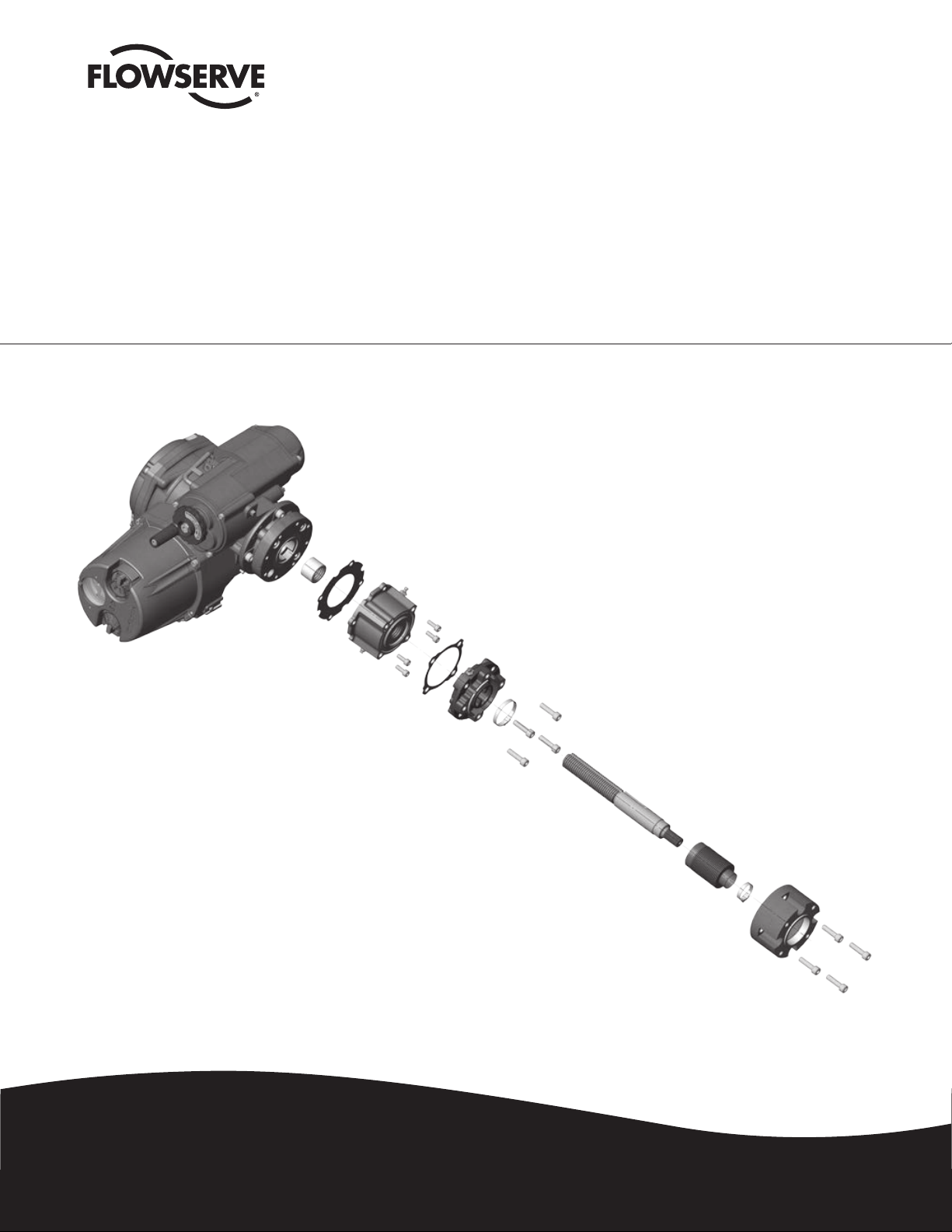
MXa/QXM Linear Base
FCD LMENIM2315-00 – 6/14
Installation
Operation
Maintenance
Experience In Motion
Page 2

MXa/QXM Linear Base FCD LMENIM2315-00 – 6/14
Contents
1 Subassembly Instructions 3
1.1 LB Subassembly, QXM and MX Units 3
1.1.1 Optional LB Subassembly Removal From QXM and MX Units 3
1.1.2 Optional LB FA or EN (F) Base and Stop Nut Subassembly 4
1.1.3 Removal of Thrust Base Subassembly From LB Assembly 5
1.1.4 Disassembly of LB Subassembly 6
2 Reassembly Instructions 7
2.1 LB Reassembly 7
2.1.1 Reassembly of Optional LB Subassembly 7
2.1.2 Reassembly of Thrust Base to LB Subassembly 8
2.1.3 Reassembly of Optional FA/EN (F) Base to LB Subassembly 8
2.1.4 Assembly or Adjustment of Optional Stop Nut for LB Subassembly 10
2.1.5 LB Lubrication 11
2.1.6 Reassembly of QXM or MX Actuators to LB/Thrust Base Assembly 11
Figures
Figure 1.1 – LB Subassembly Removal From Actuator 3
Figure 1.2 – Optional LB FA/EN (F) Base and Stop Nut Subassembly 4
Figure 1.3 – Thrust Base with LB Assembly 5
Figure 1.4 – LB Assembly 6
Figure 2.1 – LB1 Subassembly Cross-Section 9
Figure 2.2 – LB2 Subassembly Cross-Section 9
Tables
Table 1.1 – Optional LB1 and LB2 Subassembly 4
2
Page 3
MXa/QXM Linear Base FCD LMENIM2315-00 – 6/14
1 Subassembly Instructions
1.1 LB Subassembly, QXM and MX Units
1.1.1 Optional LB Subassembly Removal From QXM and MX Units
Step 1
c WARNING: Hazardous voltage! Turn off all power sources to actuator before removing actuator from LB assembly.
Power sources may include main power or control power. If necessary, disconnect incoming power leads L1, L2,
L3 and control wiring from terminal block.
Step 2
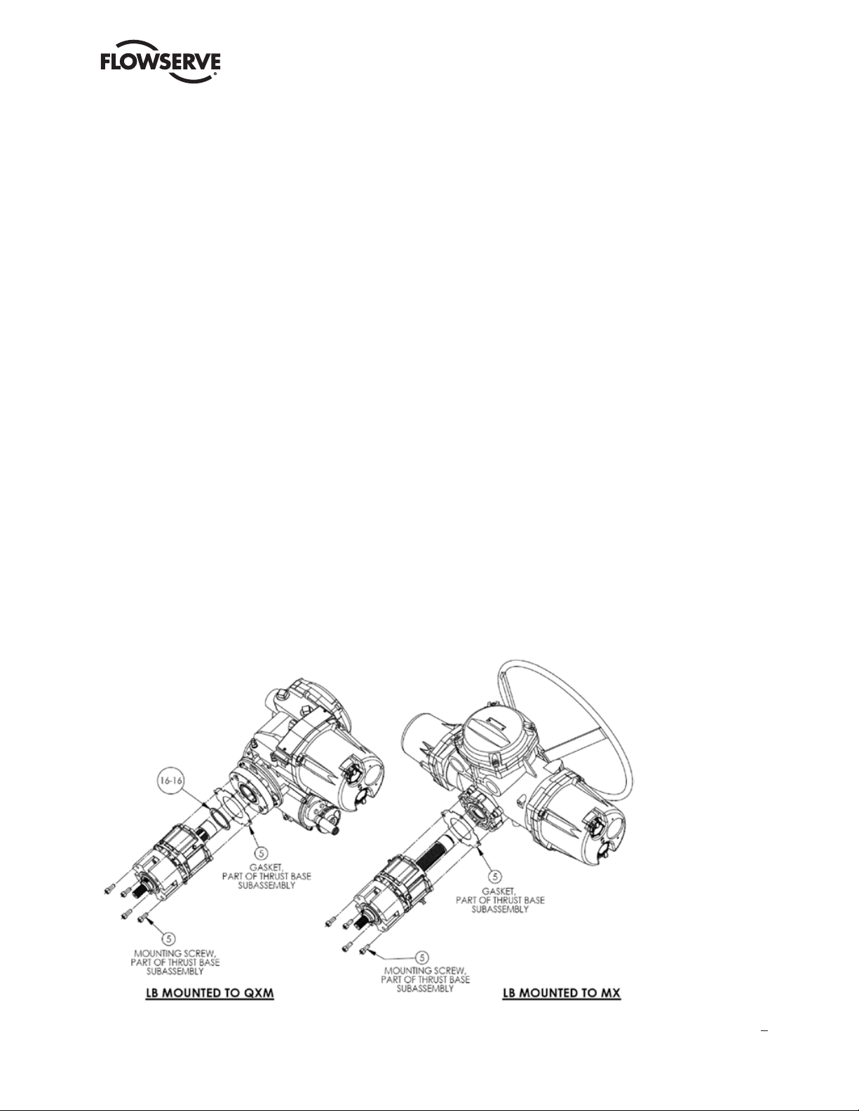
Remove the four bolts (#5) that secure the LB assembly to the actuator base plate and slide down the LB subassembly
until the LB shaft clears the unit actuator.
Step 3
Remove gasket (#5) and slide gasket off thrust base assembly or remove from actuator baseplate.
Step 4 (QXM actuators only)
Remove pilot spacer (#16-16) by sliding over LB shaft.
NOTE: Pilot spacer (#16-16) is used to pilot an ISO thrust base assembly to the QXM adapter plate. If an MSS thrust
base assembly is used on a QXM actuator, the pilot spacer is not required. The MX units do not require this pilot spacer
in this location on any assemblies as long as the MX base plate and thrust base are of the same type, i.e., ISO/ISO or
MSS/MSS.
Figure 1.1 – LB Subassembly Removal From Actuator
NOTE: The thrust base assembly is considered part of the LB subassembly. For this procedure the thrust base parts
are called out as item number (#5) in the figures. Other item numbers may be used in other manuals. For disassembly
and reassembly of the thrust base assembly (#5), refer to the QXM or MX manuals, (QXM) LMENIM3314 section 3
and (MX) LMENIM2306 section 3.
3
flowserve.com
Page 4
MXa/QXM Linear Base FCD LMENIM2315-00 – 6/14
1.1.2 Optional LB FA or EN (F) Base and Stop Nut Subassembly
NOTE: The EN (F) base meets standard DS/EN 15714-2 but has the same mounting as an ‘F’ ISO style base.
Step 1
(Optional Stop Nut if supplied) Remove set screw (#13) and spin nut (#12) off shaft.
NOTE: Optional nut may only be used when LB is mounted to a QXM, MX-10 or MX-40 actuator.
Step 2
(Optional FA/EN (F) base) Remove the four bolts (#11) that secure the optional base to the anti-rotation base (#1) and
slide the base off over shaft (#2) and bellows (#7).
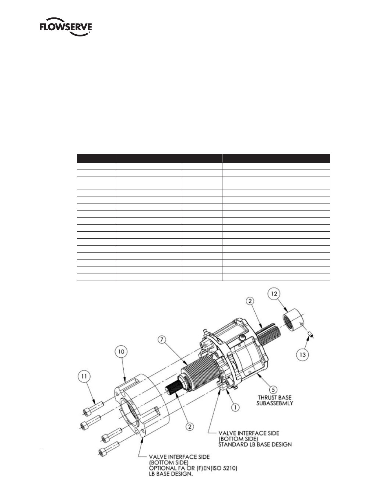
Table 1.1 – Optional LB1 and LB2 Subassembly
ITEM NUMBER DESCRIPTION QTY. NOTES
1 ANTI-ROTATION BASE 1
2 SHAFT 1
3 THRUST NUT 1
4 SOCKET HEAD CAP SCREWS 4
5 THRUST BASE ASSEMBLY 1
6 GASKET 1
7 BELLOWS AND TWO CLAMPS 1
8 GREASE FITTING 1
9 PIPE PLUG 1
10 OPTIONAL FA OR EN (F) BASE 1
11 SOCKET HEAD CAP SCREWS 4
12 OPTIONAL STOP, HW CLOSED 1 QXM, MX-10 AND MX-40 ONLY
13 SET SCREW, OPTIONAL STOP 1 QXM, MX-10 AND MX-40 ONLY
14 ANTI-ROTATION NUT 1 LB2 ONLY
15 O-RING 1 LB2 ONLY
16-16 SPACER, PILOT 1 SEE NOTES FOR USAGE
PART OF THRUST BASE ASSEMBLY, BUT MACHINED
TO MATE WITH LB ASSEMBLY
Figure 1.2 – Optional LB FA/EN (F) Base and Stop Nut Subassembly
LB1 assembly shown in this figure.
4
Page 5

MXa/QXM Linear Base FCD LMENIM2315-00 – 6/14
1.1.3 Removal of Thrust Base Subassembly From LB Assembly
Step 1
Remove the four bolts (#4) that secure the thrust base subassembly (#5) to the LB anti-rotation base (#1).
Step 2
Remove thrust base subassembly (#5) by rotating the thrust base up and around the LB shaft threads (#2) until the
thrust base is disengaged from the LB shaft.
NOTE: If the thrust base is still attached to the actuator, the LB assembly may be removed from the thrust base by
rotating the LB assembly down until the LB shaft is disengaged from the thrust base subassembly.
Step 3
Remove gasket (#6), and slide off LB assembly or remove from thrust base.
Step 4
If supplied, remove pilot spacer (#16-16) by sliding over LB shaft.
NOTE: Pilot spacer (#16-16) is used to pilot an MSS thrust base assembly (#5) to the LB anti-rotation base (#1). If an
ISO thrust base assembly is used, the pilot spacer is not required in this location.
This note applies to all LB assemblies mounted to both QXM and MX actuators.
Figure 1.3 – Thrust Base With LB Assembly
LB1 assembly shown in this figure.
flowserve.com
5
Page 6

MXa/QXM Linear Base FCD LMENIM2315-00 – 6/14
1.1.4 Disassembly of LB Subassembly
Step 1
Loosen the two clamps (#7) that secure the bellows boot in place on the anti-rotation base (#1) and shaft (#2). Slide
both clamps over the bellows boot and remove.
Step 2
Remove the bellows boot (#7) by turning and pulling off of the anti-rotation base (#1).
Step 3
Remove shaft (#2) by pulling shaft out through the bottom of the anti-rotation base (#1), as shown in Figure 1.4.
NOTE: Steps 4 and 5 are for the LB2 assembly only. The LB2 anti-rotation base consists of three parts: the base (#1),
the nut (#14) and the O-ring (#15).
Step 4
LB2 assembly only.
Remove the anti-rotation nut (#14) by pushing the nut from the bottom side of the anti-rotation base then removing
from the top side.
Step 5
LB2 assembly only.
Remove O-ring (#15) from anti-rotation nut (#14).
Figure 1.4 – LB Assembly
LB2 assembly shown in this figure.
6
Page 7

MXa/QXM Linear Base FCD LMENIM2315-00 – 6/14
2 Reassembly Instructions
2.1 LB Reassembly
2.1.1 Reassembly of Optional LB Subassembly
See Figure 1.4 for the following steps.
NOTE: Steps 1 and 2 are for the LB2 assembly only. The LB2 anti-rotation base consists of three parts: the base (#1),
the nut (#14) and the O-ring (#15). The LB1 requires only one part for the anti-rotation base (#1).
Step 1
LB2 assembly only.
Lightly lubricate O-ring (#15) and carefully slide O-ring over anti-rotation nut (#14) and into the O-ring groove.
Step 2
LB2 assembly only.
Align anti-rotation nut (#14) lugs with key slots in the anti-rotation base (#1), and slide nut into the base until seated in
base.
Step 3
Generously lubricate shaft (#2) threads and slots and anti-rotation base (#1) or nut (#14) internal lugs with Mobil SHC
220 Mobilith grease. Align the shaft key slots with the anti-rotation base (#1) lugs or (#14) nut lugs, and slide the shaft
into the anti-rotation base (#1) from the bottom side.
NOTE: Before mounting the bellows boot per the following steps, 4 thru 6, the thrust base assembly may be mounted
per section 2.1.2. Mounting of the thrust base will hold the shaft in place for assembling of the bellows boot.
Step 4
Slide the big end of the bellows boot (#7) over the bottom of the shaft (valve side), and push boot onto the anti-rotation
base boss, making sure that the boot is completely pushed onto the base or nut boss.
NOTE: The mating boss for the boot is part of the base (#1) on LB1 and is part of the nut (#14) on the LB2 assembly.
Step 5
Slide the big clamp (#7) over the boot and up to the mating bellows and base boss. Rotate clamp screw for access thru
one of the two slots in the bottom of the anti-rotation base. Secure boot to the base with clamp by tightening the clamp
to 8–10 inch-pounds.
Step 6
Gently push the bellows boot (#7) onto the smaller OD on the shaft (#2). Slide the small clamp over the shaft and boot.
Secure boot to the shaft with clamp by tightening the clamp to 8–10 inch-pounds, ensuring boot and clamp are on the
smaller OD of shaft.
flowserve.com
7
Page 8

MXa/QXM Linear Base FCD LMENIM2315-00 – 6/14
2.1.2 Reassembly of Thrust Base to LB Subassembly
See Figure 1.3 for the following steps.
Step 1
If required, place the pilot spacer (#16-16) into the top of the anti-rotation base (#1) pilot ID.
NOTE: The pilot spacer in this location is only required if using an MSS thrust base assembly. When using an ISO thrust
base assembly, the pilot spacer is not required.
Step 2
Place gasket (#6) over the shaft and place onto the top of the anti-rotation base. Place the thrust base assembly over
top of the threads of the shaft, and turn the thrust base on by threading the thrust nut to the shaft until seated on the
anti-rotation base and gasket, making sure the gasket and thrust base are centered on the anti-rotation base.
Step 3
Insert the four mounting screws (#4) thru the anti-rotation base into the thrust base and tighten.
QXM, MX-05 and MX-10, M10 or 3/8-16 screw tighten to 18–20 Ft-LBS/24–27 Nm.
MX-20 and MX-40, M16 or 5/8-11 screw tighten to 95–100 Ft-LBS/129–135 Nm.
2.1.3 Reassembly of Optional FA/EN (F) Base to LB Subassembly
See Figures 1.2, 2.1 and 2.2 for the following steps.
Step 1
Slide the optional FA/EN (F) base (#10) over the shaft and bellows boot aligning to anti-rotation base, and insert the four
mounting screws (#11) thru the optional base holes and tighten to the anti-rotation base (#1).
QXM, MX-05 and MX-10, M10 screws tighten to 18–20 Ft-LBS/24–27 Nm.
MX-20 and MX-40, M16 screws tighten to 95–100 Ft-LBS/129–135 Nm.
8
Page 9

Figure 2.1 – LB1 Subassembly Cross-Section
MXa/QXM Linear Base FCD LMENIM2315-00 – 6/14
Figure 2.2 – LB2 Subassembly Cross-Section
flowserve.com
9
Page 10

MXa/QXM Linear Base FCD LMENIM2315-00 – 6/14
2.1.4 Assembly or Adjustment of Optional Stop Nut for LB Subassembly
QXM, MX-10 and MX-40 only.
NOTE: This LB stop nut must not be used for electric motorized operation stops. The stop nut is for use of the manual
override operated closed position only.
IF LB UNIT STOP NUT IS USED FOR ACTUATOR ELECTRIC MOTORIZED CLOSED POSITION, ACTUATOR PREMATURE
FAILURE WILL OCCUR.
To assemble or adjust the stop nut, the LB subassembly must be mounted to the valve with the actuator removed.
Customer must decide on the manual override closed position of the LB unit for placement of the stop nut allowing for
coast when unit is in electric motorized operation. See steps 2 and 3 for recommended stop nut position.
Step 1
Mount the LB with thrust base assembly to valve. Using the thrust base nut lugs, rotate the LB unit to the planned
electric motorized operation closed position (Closed position is where the LB shaft on the bellows side is extended away
from the LB base).
NOTE: LB assembly with QXM/MX actuator may be mounted to valve and electric motorized to the closed position.
Once in the closed position, remove the QXM/MX actuator and proceed with stop assembly.
Step 2
Place stop nut (#12) over the top of the LB shaft (#2) and thread the stop nut down until it bottoms out on the thrust
base thrust nut (#3).
Recommended stop nut position:
Once stop nut has been threaded down to the thrust base nut back-stop off of thrust nut 1 millimeter. For a 3 mm pitch
shaft, 1 mm = 1⁄3 turn; 4 mm pitch shaft = ¼ turn; 8 mm pitch shaft = 1⁄8 turn; and a 10 mm pitch shaft = 1⁄10 turn.
Step 3
Once stop nut has been positioned, stop nut must be drilled and tap to secure stop in place and shaft must be spot
faced for the set screw. The LB1 requires an M6 set screw and the LB2 requires an M8 set screw.
NOTES:
1. The supplied set screw length is intended to be positioned where the tap drill is within one of the two slots on the
shaft. In this orientation and with small shaft spot face, the supplied set screw length will not protrude past the OD
of the stop nut and disturb the shaft threads. See Figures 2.1 or 2.2.
2. Once stop nut is assembled and actuator has been mounted to the LB unit per section 2.1.6, electrically run unit
to open and then back to the closed position. Declutch actuator and using the handwheel, manually open valve.
If valve is hard to unset in manual mode, the stop nut may be jammed and will need to be moved away from the
closed position. If stop needs readjusting, a new tap in the stop nut and shaft spot face will be required.
10
Page 11

MXa/QXM Linear Base FCD LMENIM2315-00 – 6/14
2.1.5 LB Lubrication
Step 1
Thrust base assembly (#5) lubrication.
Using only Mobil SHC 220 Mobilith grease, fill thrust base thru the grease fitting (#10-11) until grease is forced out of
the relief fitting.
Step 2
Anti-rotation base assembly lubrication.
Remove pipe plug (#9). Using only Mobil SHC 220 Mobilith grease fill anti-rotation base assembly thru the grease
fitting (#8) until grease is forced out of the pipe plug hole. Replace pipe plug.
NOTES:
1. Do not over-fill. It is best to fill the anti-rotation base assembly in the open position (stem retracted). If over-filled,
grease will be forced out when operating unit.
2. Grease at intervals of 2000 open-closed cycles and adjust depending on load profile.
2.1.6 Reassembly of QXM or MX Actuators to LB/Thrust Base Assembly
See Figure 1.1 for the following steps.
Step 1
Slide gasket (#5) or over shaft and place on top of LB thrust base. If required (QXM units with MSS base only), place
spacer pilot (#16-16) into LB thrust base pilot ID.
Step 2
Place unit actuator on top of LB subassembly and align actuator lugs, pilot and with LB thrust base lugs and pilot.
Check to make sure gasket is also aligned. Rotate actuator and gasket to align mounting holes.
Step 3
Insert mounting bolts (#5) thru thrust base and tighten to actuator.
MX-05, M10 or 3/8-16 screws, tighten to 10–12 Ft-LBS/13–16 Nm.
QXM and MX-10 M8 screws, tighten to 8–10 Ft-LBS/11–13 Nm.
MX-20 and MX-40 M12 screws, tighten to 17–20 Ft-LBS/23–27 Nm.
flowserve.com
11
Page 12

Flowserve Corporation
Flow Control
United States
Flowserve Limitorque
5114 Woodall Road
P.O. Box 11318
Lynchburg, VA 24506-1318
Phone: 434-528-4400
Fax: 434-845-9736
England
Flowserve Limitorque
Euro House
Abex Road
Newbury
Berkshire, RG14 5EY
United Kingdom
Phone: 44-1-635-46999
Fax: 44-1-635-36034
Japan
Limitorque – Nippon Gear Co., Ltd.
Asahi-Seimei Bldg. 4th Floor
1-11-11 Kita-Saiwai, Nishi-Ku
Yokohama-Shi, (220-0004)
Japan
Phone: 81-45-326-2065
Fax: 81-45-320-5962
To find your local Flowserve representative,
visit www.flowserve.com, www.limitorque.com
or call USA 1 800 225 6989.
FCD LMENIM2315-00 (E) 6/14 © 2014 Flowserve Corporation.
Flowserve Corporation has established industry leadership in the design and manufacture of its products. When properly selected, this Flowserve
product is designed to perform its intended function safely during its useful life. However, the purchaser or user of Flowserve products should be aware
that Flowserve products might be used in numerous applications under a wide variety of industrial service conditions. Although Flowserve can (and
often does) provide general guidelines, it cannot provide specific data and warnings for all possible applications. The purchaser/user must therefore
assume the ultimate responsibility for the proper sizing and selection, installation, operation, and maintenance of Flowserve products. The purchaser/
user should read and understand the Installation Operation Maintenance (IOM) instructions included with the product, and train its employees and
contractors in the safe use of Flowserve products in connection with the specific application.
While the information and specifications contained in this literature are believed to be accurate, they are supplied for informative purposes only and
should not be considered certified or as a guarantee of satisfactory results by reliance thereon. Nothing contained herein is to be construed as a
warranty or guarantee, express or implied, regarding any matter with respect to this product. Because Flowserve is continually improving and upgrading
its product design, the specifications, dimensions and information contained herein are subject to change without notice. Should any question arise
concerning these provisions, the purchaser/user should contact Flowserve Corporation at any one of its worldwide operations or offices.
© 2014 Flowserve Corporation, Irving, Texas, USA. Flowserve is a registered trademark of Flowserve Corporation.
Canada
Flowserve Limitorque
120 Vinyl Court
Woodbridge, Ontario L4L 4A3
Canada
Phone: 905-856-4565
Fax: 905-856-7905
Singapore
Limitorque Asia, Pte., Ltd.
12, Tuas Avenue 20
Singapore 638824
Phone: 65-6868-4628
Fax: 65-6862-4940
China
Limitorque Beijing, Pte., Ltd.
RM A1/A2
22/F, East Area, Hanwei Plaza
No. 7 Guanghua Road, Chaoyang District
Beijing 100004, Peoples Republic of China
Phone: 86-10-5921-0606
Fax: 86-10-6561-2702
India
Flowserve Limitorque
No. 10-12, THE OVAL, Third floor
Venkatnarayana Road
T. Nagar, Chennai 600 017
Phone: 91-44-2432-8755
and 91-44-2432-4801
Fax: 91-44-2432-8754
flowserve.com
 Loading...