


 Loading...
Quasar Gen III
User Guide
CP-6302-30-R CP-6302-31-P CP-6302-31-I
Ver. 6a |
December 13, 2018 |

© 2018 FLIR Systems, Inc. All rights reserved worldwide. No parts of this manual, in whole or in part, may be copied, photocopied, translated, or transmitted to any electronic medium or machine readable form without the prior written permission of FLIR Systems, Inc.
Names and marks appearing on the products herein are either registered trademarks or trademarks of FLIR Systems, Inc. and/or its subsidiaries. All other trademarks, trade names, or company names referenced herein are used for identification only and are the property of their respective owners.
This product is protected by patents, design patents, patents pending, or design patents pending. The contents of this document are subject to change.
FLIR Systems, Inc.
6769 Hollister Avenue
Goleta, California 93117
USA
Phone: 888.747.FLIR (888.747.3547)
International: +1.805.964.9797
For technical assistance, please call us at +1.888.388.3577 or visit the Service & Support page at www.flir.com/security.
Important Instructions and Notices to the User:
Modification of this device without the express authorization of FLIR Commercial Systems, Inc. may void the user’s authority under FCC rules to operate this device.
ii |
CP-6302-30-R, CP-6302-31-P, and CP-6302-31-I User Guide |
December 13, 2018 |
|

Proper Disposal of Electrical and Electronic Equipment (EEE)
The European Union (EU) has enacted Waste Electrical and Electronic Equipment Directive 2012/19/EU (WEEE), which aims to prevent EEE waste from arising; to encourage reuse, recycling, and recovery of EEE waste; and to promote environmental responsibility.
In accordance with these regulations, all EEE products labeled with the “crossed out wheeled bin” either on the product itself or in the product literature must not be
disposed of in regular rubbish bins, mixed with regular household or other commercial waste, or by other regular municipal waste collection means. Instead, and in order to prevent possible harm to the environment or human health, all EEE products (including any cables that came with the product) should be responsibly discarded or recycled.
To identify a responsible disposal method nearby, please contact the local waste collection or recycling service, the original place of purchase or product supplier, or the responsible government authority in the area. Business users should contact their supplier or refer to their purchase contract.
Document History |
|
|
Version |
Date |
Comment |
Ver. 1 UL |
March 27, |
Third Release |
|
2018 |
|
Ver. 6a |
December |
QR-code access to product documentation |
|
13, 2018 |
and software downloads |
|
|
SD Card min/max |
December 13, 2018 |
CP-6302-30-R, CP-6302-31-P, and CP-6302-31-I User Guide |
iii |
|

iv |
CP-6302-30-R, CP-6302-31-P, and CP-6302-31-I User Guide |
December 13, 2018 |

|
|
|
|
|
Table of Contents |
|
|
||||
Table of Contents |
|
||||
1. |
Document Scope and Purpose ..................................................................................... |
1 |
|||
2. |
Accessing Camera Information from the Web .............................................................. |
7 |
|||
3. |
Overview ...................................................................................................................... |
|
9 |
||
|
3.1 |
Features |
.............................................................................................................. |
10 |
|
|
3.2 |
Package Contents ................................................................................................ |
11 |
||
4. |
Introduction to the Quasar CP-6302 Range of PTZ Cameras ....................................... |
13 |
|||
|
4.1 |
Camera Dimensions ............................................................................................. |
13 |
||
|
4.2 |
Camera Connectors - All models ........................................................................... |
14 |
||
|
4.2.1 Connecting Power to the Camera ....................................................................... |
16 |
|||
|
4.2.2 |
Connecting the Unit to the Network .................................................................... |
19 |
||
|
4.3 |
System Requirements .......................................................................................... |
19 |
||
5. |
Installation .................................................................................................................. |
|
21 |
||
|
5.1 |
Safety Lanyard ..................................................................................................... |
21 |
||
|
5.2 |
Waterproofing the Camera Cables .......................................................................... |
21 |
||
|
5.3 |
Initial Camera Configuration ................................................................................... |
22 |
||
6. |
Using DNA to Access the Camera ............................................................................... |
25 |
|||
7. |
Configuring Communication Settings ......................................................................... |
27 |
|||
8. |
Adjusting and Framing-Up the Camera View ............................................................. |
33 |
|||
9. |
Configuration and Operation ...................................................................................... |
35 |
|||
|
9.1 |
Browser-Based Viewer Introduction ........................................................................ |
35 |
||
|
9.2 |
Live Screen .......................................................................................................... |
37 |
||
|
9.3 |
System Tab ......................................................................................................... |
40 |
||
|
9.3.1 |
System ........................................................................................................... |
41 |
||
|
9.3.2 |
Security .......................................................................................................... |
42 |
||
|
|
9.3.2.1 |
User .......................................................................................................................................... |
42 |
|
|
|
9.3.2.2 |
HTTPS ...................................................................................................................................... |
44 |
|
|
|
9.3.2.3 |
IP Filter ..................................................................................................................................... |
47 |
|
|
|
9.3.2.4 |
IEEE 802.1X ............................................................................................................................ |
48 |
|
|
9.3.3 |
Network ........................................................................................................... |
49 |
||
|
|
9.3.3.1 |
Basic ......................................................................................................................................... |
49 |
|
|
|
9.3.3.2 |
QoS ........................................................................................................................................... |
51 |
|
|
|
9.3.3.3 |
SNMP ....................................................................................................................................... |
52 |
|
|
|
9.3.3.4 |
UPnP ........................................................................................................................................ |
53 |
|
|
|
9.3.3.5 |
DDNS ....................................................................................................................................... |
54 |
|
|
|
9.3.3.6 |
Mail ............................................................................................................................................ |
55 |
|
December 13, 2018 |
CP-6302-30-R, CP-6302-31-P, and CP-6302-31-I User Guide |
v |
|

Table of Contents
Table of Contents
9.3.3.7 |
FTP ............................................................................................................................................ |
56 |
9.3.3.8 |
HTTP ......................................................................................................................................... |
57 |
9.3.4 Events Setup ................................................................................................... |
57 |
|
9.3.4.1 |
IO ............................................................................................................................................... |
58 |
9.3.4.2 |
Network Failure Detection .................................................................................................... |
60 |
9.3.4.3 |
Tampering ............................................................................................................................... |
61 |
9.3.4.4 |
Periodic Event ......................................................................................................................... |
63 |
9.3.4.5 |
Manual Trigger ........................................................................................................................ |
64 |
9.3.4.6 |
Audio Detection ...................................................................................................................... |
66 |
9.3.4.7 |
Triggered Actions ................................................................................................................... |
68 |
9.3.5 |
Edge Recording ............................................................................................... |
71 |
||
|
9.3.5.1 |
SD Card ................................................................................................................................... |
71 |
|
|
9.3.5.2 |
Network Share ........................................................................................................................ |
73 |
|
|
9.3.5.3 |
Recording ................................................................................................................................ |
75 |
|
9.3.6 |
Motion Detection .............................................................................................. |
76 |
||
9.3.7 |
Schedule ......................................................................................................... |
78 |
||
9.3.8 |
File Location .................................................................................................... |
79 |
||
9.3.9 |
Maintenance .................................................................................................... |
79 |
||
|
9.3.9.1 |
Log File .................................................................................................................................... |
80 |
|
|
9.3.9.2 |
User Information .................................................................................................................... |
81 |
|
|
9.3.9.3 |
Factory Default ........................................................................................................................ |
82 |
|
|
9.3.9.4 |
Software Version .................................................................................................................... |
83 |
|
|
9.3.9.5 |
Software Upgrade .................................................................................................................. |
84 |
|
|
9.3.9.6 |
Parameters ............................................................................................................................. |
85 |
|
9.4 |
Import/Export ....................................................................................................... |
86 |
||
9.5 |
Streaming Tab ..................................................................................................... |
86 |
||
9.5.1 |
Video Configuration .......................................................................................... |
87 |
||
|
9.5.1.1 |
Video Resolutions ................................................................................................................. |
88 |
|
9.5.2 |
Video Rotation ............................................................................................... |
102 |
||
9.5.3 |
Video Text Overlay ......................................................................................... |
103 |
||
9.5.4 |
Video OCX Protocol ........................................................................................ |
104 |
||
9.5.5 |
Audio |
............................................................................................................ |
105 |
|
9.6 |
Camera Tab ....................................................................................................... |
106 |
||
9.6.1 |
Exposure Screen ............................................................................................ |
107 |
||
|
9.6.1.1 |
Auto Iris Mode ....................................................................................................................... |
108 |
|
vi |
CP-6302-30-R, CP-6302-31-P, and CP-6302-31-I User Guide |
December 13, 2018 |
|

|
|
|
|
Table of Contents |
|
|
|||
Table of Contents |
|
|||
|
9.6.1.2 |
P-Iris Priority Mode ............................................................................................................... |
108 |
|
|
9.6.1.3 |
Iris Priority Mode ................................................................................................................... |
109 |
|
|
9.6.1.4 |
Auto Shutter Mode ................................................................................................................ |
109 |
|
|
9.6.1.5 |
Shutter Priority Mode ........................................................................................................... |
110 |
|
|
9.6.1.6 |
Manual Mode ........................................................................................................................ |
110 |
|
9.6.2 |
Picture Adjustment ......................................................................................... |
112 |
||
9.6.3 |
Advanced Picture Settings .............................................................................. |
113 |
||
|
9.6.3.1 |
White Balance ...................................................................................................................... |
113 |
|
|
9.6.3.2 |
Backlight Compensation .................................................................................................... |
114 |
|
|
9.6.3.3 |
WDR Function ...................................................................................................................... |
114 |
|
|
9.6.3.4 |
Noise Reduction Settings .................................................................................................. |
114 |
|
9.6.4 |
IR Function .................................................................................................... |
115 |
||
9.6.5 |
Misc. Screen ................................................................................................. |
117 |
||
9.7 |
PTZ Tab |
............................................................................................................. |
119 |
|
9.7.1 |
Preset ........................................................................................................... |
120 |
||
9.7.2 |
Pattern .......................................................................................................... |
120 |
||
9.7.3 |
Auto Pan ....................................................................................................... |
121 |
||
9.7.4 |
Sequence ...................................................................................................... |
122 |
||
9.7.5 |
Home |
............................................................................................................ |
123 |
|
9.7.6 |
Tilt Range ...................................................................................................... |
123 |
||
9.7.7 |
Privacy Mask ................................................................................................. |
124 |
||
9.7.8 |
PTZ Setting .................................................................................................... |
125 |
||
9.7.9 |
RS485 ........................................................................................................... |
126 |
||
9.8 |
Log Out |
............................................................................................................. |
126 |
|
10. Appendices ............................................................................................................... |
|
127 |
||
10.1 |
Technical Specifications ...................................................................................... |
128 |
||
10.1.1 Accessing General Camera Information ............................................................ |
128 |
|||
10.2 |
Internet Security Settings .................................................................................... |
129 |
||
10.3 |
Install UPnP Components ................................................................................... |
131 |
||
10.4 Installing and Deleting the Web Player ................................................................. |
133 |
|||
10.5 Connecting Leads to a Spring Clamp Terminal Block ............................................. |
135 |
|||
10.6 |
Deleting Temporary Internet Files ......................................................................... |
136 |
||
10.7 Camera and Mounting Accessories ...................................................................... |
137 |
|||
December 13, 2018 |
CP-6302-30-R, CP-6302-31-P, and CP-6302-31-I User Guide |
vii |
|

viii |
CP-6302-30-R, CP-6302-31-P, and CP-6302-31-I User Guide |
December 13, 2018 |
Document Scope and Purpose
1 Document Scope and Purpose
The purpose of this document is to provide an overall guide to the CP-6302-3x Range. cameras. Basic setup procedures are provided herein. After completing physical installation as described in the relevant Installation Manual, additional setup and configurations are required before video analysis and detection can commence.
Note:
This document is intended for use by technical users who have a basic understanding of CCTV camera/video equipment and LAN/WAN network connections.
Remarque:
Ce document est destiné aux utilisateurs techniciens qui possèdent des connaissances de base des équipements vidéo/caméras de télésurveillance et des connexions aux réseaux LAN/WAN.
Warning:
Installation must follow safety, standards, and electrical codes as well as the laws that apply where the units are being installed.
Avertissement:
L'installation doit respecter les consignes de sécurité, les normes et les codes électriques, ainsi que la législation en vigueur sur le lieu d'implantation des unités.
DIsclaimer |
Avis de non-responsabilité |
Users of FLIR products accept full responsibility for ensuring the suitability and considering the role of the product detection capabilities and their limitation as they apply to their unique site requirements.
FLIR Systems, Inc. and its agents make no guarantees or warranties to the suitability for the users’ intended use. FLIR Systems, Inc. accepts no responsibility for improper use or incomplete security and safety measures.
Failure in part or in whole of the installer, owner, or user in any way to follow the prescribed procedures or to heed WARNINGS and CAUTIONS shall absolve FLIR and its agents from any resulting liability.
Specifications and information in this guide are subject to change without notice.
Il incombe aux utilisateurs des produits FLIR de vérifier que ces produits sont adaptés et d'étudier le rôle des capacités et limites de détection du produit appliqués aux exigences uniques de leur site.
FLIR Systems, Inc. et ses agents ne garantissent d'aucune façon que les produits sont adaptés à l'usage auquel l'utilisateur les destine. FLIR Systems, Inc. ne pourra être tenu pour responsable en cas de mauvaise utilisation ou de mise en place de mesures de sécurité insuffisantes.
Le non respect de tout ou partie des procédures recommandées ou des messages d'AVERTISSEMENT ou d'ATTENTION de la part de l'installateur, du propriétaire ou de l'utilisateur dégagera FLIR Systems, Inc. et ses agents de toute responsabilité en résultant.
Les spécifications et informations contenues dans ce guide sont sujettes à modification sans préavis.
December 13, 2018 |
CP-6302-30-R, CP-6302-31-P, and CP-6302-31-I User Guide |
1 |
|

Document Scope and Purpose
A Warning is a precautionary message that indicates a procedure or condition where there are potential hazards of personal injury or death.
Avertissement est un message préventif indiquant qu'une procédure ou condition présente un risque potentiel de blessure ou de mort.
A Caution is a precautionary message that indicates a procedure or condition where there are potential hazards of permanent damage to the equipment and or loss of data.
Attention est un message préventif indiquant qu'une procédure ou condition présente un risque potentiel de dommages permanents pour l'équipement et/ou de perte de données.
A Note is useful information to prevent problems, help with successful installation, or to provide additional understanding of the products and installation.
Une Remarque est une information utile permettant d'éviter certains problèmes, d'effectuer une installation correcte ou de mieux comprendre les produits et l'installation.
A Tip is information and best practices that are useful or provide some benefit for installation and use of FLIR products.
Un Conseil correspond à une information et aux bonnes pratiques utiles ou apportant un avantage supplémentaire pour l'installation et l'utilisation des produits FLIR.
2 |
CP-6302-30-R, CP-6302-31-P, and CP-6302-31-I User Guide |
December 13, 2018 |
|
Document Scope and Purpose
General Cautions and Warnings
This section contains information that indicates a
procedure or condition where there are potential hazards.
SAVE ALL SAFETY AND OPERATING INSTRUCTIONS
FOR FUTURE USE.
Although the unit is designed and manufactured in compliance with all applicable safety standards, certain hazards are present during the installation of this equipment.
To help ensure safety and to help reduce risk of injury or damage, observe the following:
Précautions et avertissements d'ordre général
Cette section contient des informations
indiquant qu'une procédure ou condition
présente des risques potentiels.
CONSERVEZ TOUTES LES
INSTRUCTIONS DE SÉCURITÉ ET
D'UTILISATION POUR POUVOIR VOUS Y
RÉFÉRER ULTÉRIEUREMENT.
Bien que l'unité soit conçue et fabriquée conformément à toutes les normes de sécurité en vigueur, l'installation de cet équipement présente certains risques.
Afin de garantir la sécurité et de réduire les risques de blessure ou de dommages, veuillez respecter les consignes suivantes:
Caution:
The unit’s cover is an essential part of the product. Do not open or remove it.
Never operate the unit without the cover in place. Operating the unit without the cover poses a risk of fire and shock hazards.
Do not disassemble the unit or remove screws. There are no user serviceable parts inside the unit.
Only qualified trained personnel should service and repair this equipment.
Observe local codes and laws and ensure that installation and operation are in accordance with fire, security and safety standards.
Attention:
Le cache de l'unité est une partie essentielle du produit. Ne les ouvrez et ne les retirez pas.
N'utilisez jamais l'unité sans que le cache soit en place. L'utilisation de l'unité sans cache présente un risque d'incendie et de choc électrique.
Ne démontez pas l'unité et ne retirez pas ses vis. Aucune pièce se trouvant à l'intérieur de l'unité ne nécessite un entretien par l'utilisateur.
Seul un technicien formé et qualifié est autorisé à entretenir et à réparer cet équipement.
Respectez les codes et réglementations locaux, et assurez-vous que l'installation et l'utilisation sont conformes aux normes contre l'incendie et de sécurité.
December 13, 2018 |
CP-6302-30-R, CP-6302-31-P, and CP-6302-31-I User Guide |
3 |
|
Document Scope and Purpose
Caution:
Do not drop the camera or subject it to physical shock.
Do not touch sensor modules with fingers. If cleaning is necessary, use a clean cloth with a bit of ethanol and wipe it gently. If the camera will not be used for an extended period of time, put on the lens cap to protect the sensor from dirt.
Do not aim the camera lens at strong light, such as the sun or an incandescent lamp, which can seriously damage the camera.
Make sure that the surface of the sensor is not exposed to a laser beam, which could burn out the sensor.
If the camera will be fixed to a ceiling, verify that the ceiling can support more than 112 newtons (112-N) of gravity, or over three times the camera’s weight.
The camera should be packed in its original packing if it is reshipped.
Caution:
To avoid damage from overheating or unit failure, assure that there is sufficient temperature regulation to support the unit’s requirements (cooling/heating). Operating temperature should be kept within the range indicated in the Technical Specifications section.
Attention:
Afin d'éviter tout dommage dû à une surchauffe ou toute panne de l'unité, assurez-vous que la régulation de température est suffisante pour répondre aux exigences de l'unité (refroidissement/chauffage). La température de fonctionnement doit être maintenue dans l'intervalle indiqué dans la section Spécifications Techniques.
4 |
CP-6302-30-R, CP-6302-31-P, and CP-6302-31-I User Guide |
December 13, 2018 |
|

Document Scope and Purpose
Site Preparation
There are several requirements that should be properly addressed prior to installation at the site. The following specifications are requirements for proper installation and operation of the unit:
Ambient Environment Conditions: Avoid positioning the unit near heaters or heating system outputs. Avoid exposure to direct sunlight. Use proper maintenance to ensure that the unit is free from dust, dirt, smoke, particles, chemicals, smoke, water or water condensation, and exposure to EMI.
Accessibility: The location used should allow easy access to unit connections and cables.
Safety: Cables and electrical cords should be routed in a manner that prevents safety hazards, such as from tripping, wire fraying, overheating, etc. Ensure that nothing rests on the unit’s cables or power cords.
Ample Air Circulation: Leave enough space around the unit to allow free air circulation.
Cabling Considerations: Units should be placed in locations that are optimal for the type of video cabling used between the unit and the cameras and external devices. Using a cable longer than the manufacturer’s specifications for optimal video signal may result in degradation of color and video parameters.
Physical Security: The unit provides threat detection for physical security systems. In order to ensure that the unit cannot be disabled or tampered with, the system should be installed with security measures regarding physical access by trusted and un-trusted parties.
Network Security: The unit transmits over IP to security personnel for video surveillance. Proper network security measures should be in place to assure networks remain operating and free from malicious interference. Install the unit on the backbone of a trusted network.
Electrostatic Safeguards: The unit and other equipment connected to it (relay outputs, alarm inputs, racks, carpeting, etc.) shall be properly grounded to prevent electrostatic discharge.
The physical installation of the unit is the first phase of making the unit operational in a security plan. The goal is to physically place the unit, connect it to other devices in the system, and to establish network connectivity. When finished with the physical installation, complete the second phase of installation, which is the setup and configuration of the unit.
December 13, 2018 |
CP-6302-30-R, CP-6302-31-P, and CP-6302-31-I User Guide |
5 |
|

6 |
CP-6302-30-R, CP-6302-31-P, and CP-6302-31-I User Guide |
December 13, 2018 |
Accessing Camera Information from the Web
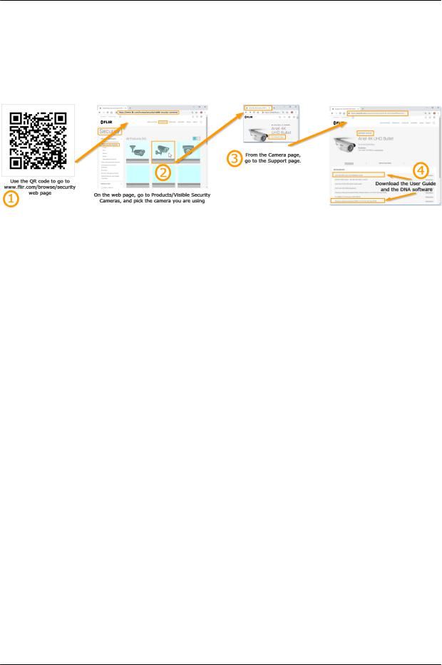
2 Accessing Camera Information from
the Web
You will find the latest information, versions of documentation and releases of software on the FLIR
website.
December 13, 2018 |
CP-6302-30-R, CP-6302-31-P, and CP-6302-31-I User Guide |
7 |
|

8 |
CP-6302-30-R, CP-6302-31-P, and CP-6302-31-I User Guide |
December 13, 2018 |
Overview
3 Overview
The Quasar Gen III CP-6302-3x Range Pan/Tilt/Zoom (PTZ) cameras provide real-time video with highdefinition quality at Full HD 1080p. The CP-6302-3x Range features gyro-based electronic image stabilization, servo feedback for precise preset positioning at frames rates up to 50/60 fps, and True Shutter Wide Dynamic Range at frames rates up to 25/30 fps. With 10x digital zoom, 30x optical zoom, and highspeed PTZ functionality, the Quasar Gen III CP-6302 can quickly cover a wide monitoring area with a high level of detail. The CP-6302-31-I model also features IR illumination up to 200 meters (656 feet)
Up to four streams can be run simultaneously with H.265, H.264 or MJPEG compression, providing an ideal solution when differing levels of image quality are required. The camera can increase frame rate and level of detail when events are triggered. In addition, FLIR's adaptive streaming algorithms provide the highest image quality with the lowest bandwidth and storage requirements.
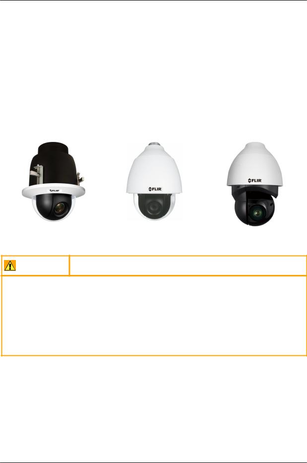
CP-6302-30-R |
CP-6302-31-P |
CP-6302-31-I |
||
|
|
|
|
|
|
|
|
|
|
Caution:
If you are using FLIR’s Latitude VMS, we recommend that you configure the camera’s settings via the AdminCenter. This is because the camera’s web-based interface might be overwritten by Latitude settings. Refer to the Latitude online help for information regarding configuring camera settings.
Attention:
Si vous utilisez le logiciel de gestion de vidéo Latitude de FLIR, nous vous conseillons de configurer les paramètres de la caméra via l'AdminCenter. En effet, l'interface Internet de la caméra peut être remplacée par les paramètres Latitude. Veuillez consulter l'aide en ligne Latitude pour de plus amples informations sur la configuration des paramètres de la caméra.
December 13, 2018 |
CP-6302-30-R, CP-6302-31-P, and CP-6302-31-I User Guide |
9 |
|

Overview
3.1 |
Features |
|
|
|
|
10x digital zoom and |
1/2.8” Sony Progressive |
Four encoder streams |
|||
30x optical zoom |
scan CMOS sensor |
|
|||
Low-lux mode |
True day/night (ICR) |
PTZ tracking |
|||
Infrared LED illuminator |
IR coverage up to 200m |
IR illumination adjusted by |
|||
(see Note 1) |
(see Note 1) |
zoom ratio |
|||
|
|
|
|
|
(see Note 1) |
White Balance, Backlight |
2DNR/3DNR/ColorNR |
Up to 50/60 fps frame rate |
|||
Compensation, and WDR |
|
|
|
|
|
Built-in web application/web |
HTTP streaming MJPEG |
H.265, H.264 and MJPEG |
|||
server |
|
|
|
compression |
|
Two-way audio |
4 alarm input driven events |
2 relay output actions on alarm |
|||
Edge motion detection |
Electrical Image Stabilizer |
Six exposure modes |
|||
Detection event driven alarms |
Remote firmware upgrade |
Dual HTTP notification server |
|||
|
|
|
|
|
support (up to two servers) |
FTP upload |
Upload alarm images to FTP |
Send images on alarm to e-mail |
|||
(up to two locations) |
|
|
|
|
|
E-mail SMTP alarm |
Up to 128GB microSDXC |
|
|
Record snapshots to SD card/ |
|
|
|||||
notification (up to two |
recording support |
microSDXC card or NAS on |
|||
e-mails) |
|
|
|
alarm |
|
Sequential snapshot |
SNMP v1/v2/v3 and SNMP |
20 privacy masks |
|||
numbering |
traps |
|
|||
ONVIF support |
RTSP support |
Per-user permissions |
|||
Security IP restricted access |
Multiple users |
Group permissions |
|||
allow/deny list |
|
|
|
|
|
UPnP support |
Vandal-proof IP66 |
Built-in heater |
|||
|
|
enclosure |
|
||
Servo motor for precise |
Supports PoE++, UPOE, |
Analog, IP and RS-485 output |
|||
positioning and preset |
12VDC, and 24VAC |
connections |
|||
location |
|
|
|
|
|
Notes:
1. Only in IR model
10 |
CP-6302-30-R, CP-6302-31-P, and CP-6302-31-I User Guide |
December 13, 2018 |
|
Overview
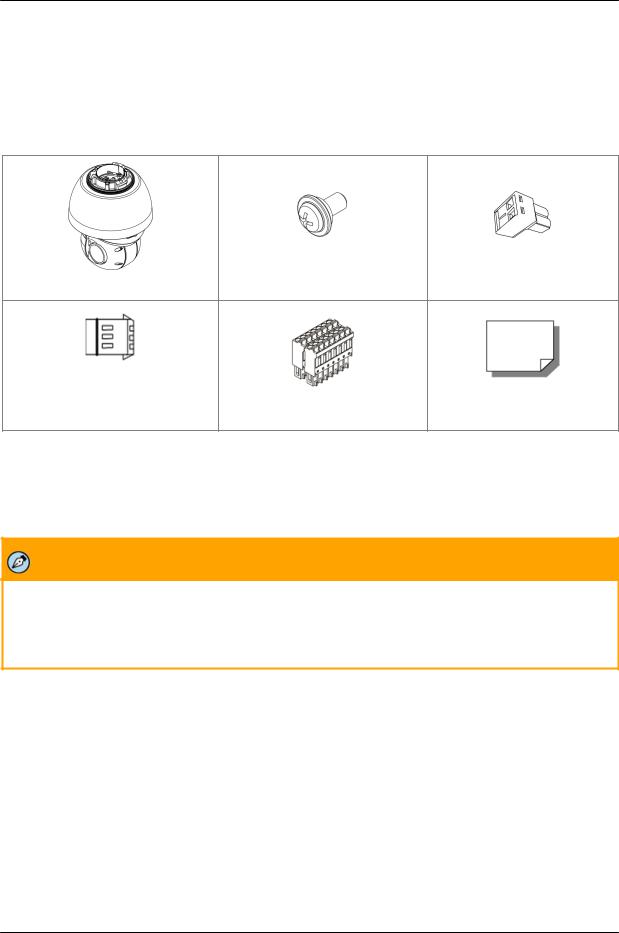
3.2Package Contents
Before proceeding, check that the box contains the items listed here. If any item is missing or has defects, do not install or operate the product. Contact your dealer for assistance.
Note: Package Contents vary slightly betw een models - See Installation Manual
|
Hard Ceiling Mount |
2-Pin 12VDC Power |
Camera Body* |
M4 Screw with Rubber Gasket |
Terminal Block |
3-Pin 24VAC Power |
14-Pin Alarm/Audio I/O |
|
Terminal Block |
Terminal Block |
Quick Installation Guide |
Package Contents
Notes:
1.CP-6302-30-R is supplied without the upper cover.
2.CP-6302-30-R and CP-6302-31-P are supplied with transparent dome. See Installation Guide for further details
Note:
The self-tapping screws are mainly for softer substrate/material installation such as wood. For other installation materials such as cement ceilings, it is necessary to pre-drill and use plastic anchors before fastening the supplied self-tapping screws into the wall.
Related Documentation
CP-6302 Installation Manual
CP-6302 Quick Installation Guide (for the relevant model)
DNA 2.1 User Manual
December 13, 2018 |
CP-6302-30-R, CP-6302-31-P, and CP-6302-31-I User Guide |
11 |
|

12 |
CP-6302-30-R, CP-6302-31-P, and CP-6302-31-I User Guide |
December 13, 2018 |
Introduction to the Quasar CP-6302 Range of PTZ Cameras
4 Introduction to the Quasar CP-6302
Range of PTZ Cameras
This chapter provides information about the camera hardware for reference before installation. The connectors included on the camera’s system cable are described.
Camera Dimensions
Camera Connectors
4.1Camera Dimensions
Following are the camera’s dimensions.
CP-602-30-R
CP-6302-30-P
December 13, 2018 |
CP-6302-30-R, CP-6302-31-P, and CP-6302-31-I User Guide |
13 |
|

Introduction to the Quasar CP-6302 Range of PTZ Cameras
CP-6302-31-I
Notes:
1.The P and R models are supplied w ith a clear dome.
2.30R Recessed model has different top cover.
4.2Camera Connectors - All models
Following are an illustration and explanation of the connectors located on the PTZ camera’s connector
panel.
|
|
|
Connector Locations |
|
|
|
(IR model shown) |
|
|
|
|
|
Callout |
Description/Label |
Comments |
|
1 |
DC12V IN |
12VDC two-pin terminal block connector. See pin assignment below. |
|
|
|
The 12VDC connector and 24VAC connector cannot be used at the |
|
|
|
same time. |
|
2 |
LAN |
RJ45 connector for 10/100 Mbps Network and PoE++/UPOE (IEEE |
|
|
|
802.3bt) connections. |
|
3 |
AC24V IN |
24VAC three-pin power terminal block. See pin assignment below. |
|
|
|
|
|
|
|
|
14 |
CP-6302-30-R, CP-6302-31-P, and CP-6302-31-I User Guide |
December 13, 2018 |
|
Introduction to the Quasar CP-6302 Range of PTZ Cameras
|
Callout |
Description/Label |
Comments |
|
|
|
|
The 12VDC connector and 24VAC connector cannot be used at the |
|
|
|
|
same time. |
|
|
4 |
DEFAULT |
Factory default reset button. Press the button for at least 20 seconds to |
|
|
|
|
restore factory defaults. |
|
|
5 |
AUDIO/ALARM |
14-pin terminal block for I/O and RS-485 connections. See pin |
|
|
|
OUT/ALARM IN/ |
assignment below. |
|
|
|
RS485 |
|
|
|
6 |
VIDEO |
BNC connector for analog video output. |
|
|
7 |
SD card slot |
Insert an SD card or microSDXC card with adapter (not supplied) to store |
|
|
|
|
video clips and snapshots. (Min recommended 4GB, up to 128GB, |
|
|
|
|
Class 10) |
|
|
|
|
Do not remove the card when the camera is powered on. It is not |
|
|
|
|
recommended to record 24/7 continuously. Refer to the card |
|
|
|
|
manufacturer for card stability and life expectancy. |
|
|
|
|
|
|
|
|
|
|
|
Note:
This camera features Zero Downtime Power Switching (ZDT). When the 12VDC connector and RJ45 port are connected simultaneously, the power input is from the 12VDC connector. If the 12VDC power fails, the camera switches power to the RJ45 port until the 12VDC power source is restored.
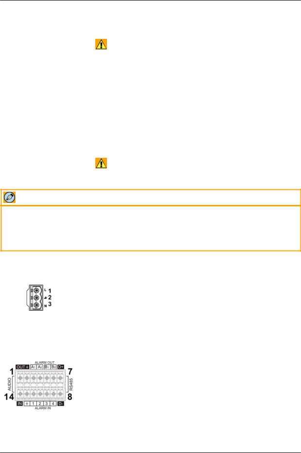
Power Connector |
Pin |
Definition |
|
1 |
AC 24L |
|
|
|
|
2 |
Ground |
|
|
|
|
3 |
AC 24N |
|
|
|
Alarm Connector |
Pin |
Definition |
Pin |
Definition |
Pin |
Definition |
|
|
1 |
Audio-Out |
6 |
Alarm-Out B2 |
11 |
Alarm-In 2 |
|
|
2 |
Ground (Audio I/O) |
7 |
RS-485 |
D+ |
12 |
Alarm-In 1 |
|
3 |
Alarm-Out A1 |
8 |
RS-485 |
D- |
13 |
Ground (Alarm I/O and |
|
|
|
|
|
|
|
RS-485) |
|
4 |
Alarm-Out A2 |
9 |
Alarm-In 4 |
14 |
Audio-In |
|
|
5 |
Alarm-Out B1 |
10 |
Alarm-In 3 |
|
|
|
December 13, 2018 |
CP-6302-30-R, CP-6302-31-P, and CP-6302-31-I User Guide |
15 |
|

Introduction to the Quasar CP-6302 Range of PTZ Cameras
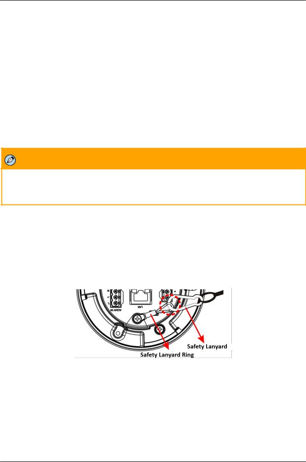
Safety Lanyard Connections
4.2.1Connecting Power to the Camera
This product is intended to be used with a Listed Power Adapter with LPS. The camera is powered by PoE+ (IEEE802.3at, class 4, CP-6302-31-P and CP-6302-30-R only), UPOE (CP-6302-31-I, CP-6302-31-P, and CP-6302-30-R), 24VAC, or 12VDC power source (not included in the package).
If using an external power supply, connect the power leads or three-pin power terminal block to the power supply.
If using PoE++ or UPOE, make sure that a Power Sourcing Equipment (PSE) device is used in the network.
Make sure the camera’s power cable is properly connected. All electrical work must be performed in accordance with local regulatory requirements.
CP-6302-31-I
Caution:
1.If the camera is connected to a PoE network, note that the PoE supply’s rated output is 55VDC, 0.91A.
2.If the camera is installed for outdoor use, the PoE supply must be installed with proper weatherproofing.
3.As a Listed Power Unit, the PoE should be marked as “LPS” or “Limited Power Source”.
4.This product shall be installed by a qualified service person. Installation shall conform to all local codes.
5.If the camera is connected to a 12VDC power supply, the power rating is 4.17A
6.If the camera is connected to a 24VAC, 50-60Hz power supply, the power rating is 2.09A
Attention:
1.Si la caméra est connectée à un réseau PoE, notez que la puissance nominale de l'alimentation PoE est 55VDC, 0.91A.
2.Si la caméra est installée pour une utilisation extérieure, l'alimentation PoE doit être installé avec l'étanchéisation appropriée.
3.Comme une unité d'alimentation «Listed», le PoE doit être marqué comme «LPS» ou «Limited Power Source".
4.Ce produit doit être installé par un technicien qualifié. L'installation doit se conformer à tous les codes locaux.
5.Si la caméra est connecté à une unité d'alimentation 12V cc, la puissance nominale est 4.17A.
6.Si la caméra est connecté à une unité d'alimentation 24V ca,50-60Hz la puissance nominale est 2.09A.
For CP-6302-31-P:
Caution:
1.If the camera is connected to a PoE network, note that the PoE supply's rated output is 55VDC, 0.39A.
16 |
CP-6302-30-R, CP-6302-31-P, and CP-6302-31-I User Guide |
December 13, 2018 |
|

Introduction to the Quasar CP-6302 Range of PTZ Cameras
2.If the camera is installed for outdoor use, the PoE supply must be installed with proper weatherproofing.
3.As a Listed Power Unit, the PoE should be marked as “LPS” or “Limited Power Source”.
4.This product shall be installed by a qualified service person. Installation shall conform to all local codes.
5.If the camera is connected to a 12VDC power supply, the power rating is 1.62A.
6.If the camera is connected to a 24VAC, 50-60Hz power supply, the power rating is 0.67A.
Attention:
1.Si la caméra est connectée à un réseau PoE, notez que la puissance nominale de l'alimentation PoE est 55VDC, 0.39A.
2.Si la caméra est installée pour une utilisation extérieure, l'alimentation PoE doit être installé avec l'étanchéisation appropriée.
3.Comme une unité d'alimentation «Listed», le PoE doit être marqué comme «LPS» ou «Limited Power Source".
4.Ce produit doit être installé par un technicien qualifié. L'installation doit se conformer à tous les codes locaux.
5.Si la caméra est connecté à une unité d'alimentation 12V cc, la puissance nominale est 1.62A.
6.Si la caméra est connecté à une unité d'alimentation 24V ca,50-60Hz la puissance nominale est 0.67A.
For CP-6302-30-R:
Caution:
1.If the camera is connected to a PoE network, note that the PoE supply's rated output is 55VDC, 0.24A.
2.As a Listed Power Unit, the PoE should be marked as “LPS” or “Limited Power Source”.
3.This product shall be installed by a qualified service person. Installation shall conform to all local codes.
4.If the camera is connected to a 12VDC power supply, the power rating is 0.91A.
5.If the camera is connected to a 24VAC, 50-60Hz power supply, the power rating is 0.38A.
Attention:
1.Si la caméra est connectée à un réseau PoE, notez que la puissance nominale de l'alimentation PoE est 55VDC, 0.24A.
2.Comme une unité d'alimentation «Listed», le PoE doit être marqué comme «LPS» ou «Limited Power Source".
3.Ce produit doit être installé par un technicien qualifié. L'installation doit se conformer à tous les codes locaux.
4.Si la caméra est connecté à une unité d'alimentation 12V cc, la puissance nominale est 0.91A.
5.Si la caméra est connecté à une unité d'alimentation 24V ca,50-60Hz la puissance nominale est 0.38A.
December 13, 2018 |
CP-6302-30-R, CP-6302-31-P, and CP-6302-31-I User Guide |
17 |
|

Introduction to the Quasar CP-6302 Range of PTZ Cameras
Note:
An ITE PoE injector should be connected only to a PoE network inside a building and not routed outside
the building.
Warning:
1.This product contains a battery that is soldered to the PCB. There is a risk of explosion if the battery is replaced by an incorrect type. Do not replace the battery. The battery should be disposed of in accordance with manufacturer’s instructions, local codes, or WEEE standards. Replacement of the battery by the customer will void the product warranty.
Avertissement:
1.Ce produit contient une batterie soudée à la PCB. Il y a un risque d'explosion si la batterie est remplacée par un type incorrect. Ne pas remplacer la batterie. La batterie doit être éliminée conformément aux instructions du fabricant, aux codes locaux, ou aux normes WEEE. Le remplacement de la batterie par le client annulera la garantie du produit.
18 |
CP-6302-30-R, CP-6302-31-P, and CP-6302-31-I User Guide |
December 13, 2018 |
|
Introduction to the Quasar CP-6302 Range of PTZ Cameras
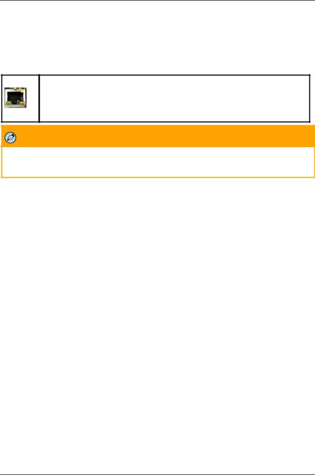
4.2.2Connecting the Unit to the Network
A Cat 5 or Cat 6 Ethernet cable is recommended for network connection. To ensure transmission quality, cable length should not exceed 100 meters (328 feet). Connect one end of the Ethernet cable to the RJ45 connector of the system cable. Plug the other end of the cable into the network switch or PC. Check the status of the link and the activity LEDs. If the LEDs are unlit, check the LAN connection.
A steady green link LED indicates a good network connection.
The yellow activity LED flashes to indicate network activity.
Note:
An Ethernet crossover cable might be needed when connecting the camera directly to the PC.
4.3System Requirements
To access the camera via a web browser, ensure that your PC has the proper network connection and meets system requirements as described below.
Item |
Minimum System Requirement |
|
|
Personal Computer |
Minimum: Intel® CoreTM i5-2430M, 2.4 GHz; 2GB RAM or more |
|
Recommended: Intel® CoreTM i7-870, 2.93 GHz; 8GB RAM |
|
|
Operating System |
Windows Server 2012; Windows 7, 8, 8.1, and 10 |
|
|
Web Browser |
Microsoft Internet Explorer 10 and above (32-bit version). IE 11 is |
|
recommended. |
|
|
Network Card |
10BaseT (10 Mbps) or 100Base-TX (100 Mbps) |
|
|
Viewer |
ActiveX control plug-in for Microsoft IE |
|
|
December 13, 2018 |
CP-6302-30-R, CP-6302-31-P, and CP-6302-31-I User Guide |
19 |
|

20 |
CP-6302-30-R, CP-6302-31-P, and CP-6302-31-I User Guide |
December 13, 2018 |
Installation
5 Installation
This camera is designed for indoor and outdoor installation*. Observe the following installation recommendations:
Always use weatherproof equipment, such as boxes, receptacles, connectors, etc. where appropriate.
For electrical wiring, use the properly rated sheathed cables for conditions to which the cable will be exposed (for example, moisture, heat, UV, physical requirements, etc.).
Plan ahead to determine where to install infrastructure weatherproof equipment. Whenever possible, ground components to an outdoor ground.
Use best security practices to design and maintain secured camera access, communications infrastructure, tamper-proof outdoor boxes, etc.
All electrical work must be performed in accordance with local regulatory requirements.
* The CP-6302-30-R (Recessed) model will normally be installed indoors
Note:
For detailed information about installation accessories and their installation, refer to the CP-6302 Installation Manual.
Related Links
Waterproofing the Camera Cables Initial Camera Configuration
5.1Safety Lanyard
For safety reasons, the camera includes a safety lanyard ring which should be connected to the safety lanyard coming from the pendant.
5.2Waterproofing the Camera Cables
The camera is IP66-rated to prevent water from entering the camera. Nevertheless, water can enter the camera if it is not installed properly. Please make sure the warnings below are strictly followed when installing the camera.
Place all cables and the adaptor in dry and well-waterproofed environments, e.g. waterproof boxes. This prevents moisture accumulation inside the camera and moisture penetration into cables.
December 13, 2018 |
CP-6302-30-R, CP-6302-31-P, and CP-6302-31-I User Guide |
21 |
|
Installation
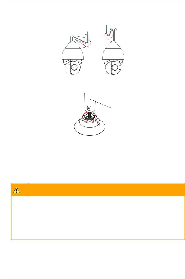
While running cables, slightly bend the cables in a U-shaped curve to create a low point (see figures below). This prevents water from entering the camera along the cables from above.
U-Shaped Cable Installation
Seal the cable entry hole of the outdoor mounting kit (see figure below) with thread seal tape to keep water from entering the camera.
Sealing Cable Entry Hole
5.3Initial Camera Configuration
To perform the initial camera configuration
1.Unpack the camera. Rotate and remove the protective cover.
2.Remove the PE cloth sheet and lens cap. Attach the dome cover to the body.
3.On the camera back plate, plug the Cat 5 cable into the camera’s Ethernet port. If the network does not use IEEE 802.3bt PoE++ or UPOE, plug a properly rated 24VAC power supply into the cameras’ power connector terminal block.
Caution:
Make sure that the power supply connection matches the positive and negative polarity on
the unit.
Attention:
Assurez-vous que le branchement à l'alimentation corresponde aux polarités positive et
négative sur l'unité.
4.Verify that the LEDs on the RJ45 connector illuminate green (indicating a stable network connection) and flashing yellow (to indicate network activity).
5.Do the following:
a.Download and run dna.exe (see note below) from the link Accessing Camera Information from the Web
22 |
CP-6302-30-R, CP-6302-31-P, and CP-6302-31-I User Guide |
December 13, 2018 |
|
Loading...