


 Loading...
Ariel Gen II
User and
Installation
Guide
CC-3103
Ver. 3 |
December 12, 2018 |

© 2018 FLIR Systems, Inc. All rights reserved worldwide. No parts of this manual, in whole or in part, may be copied, photocopied, translated, or transmitted to any electronic medium or machine readable form without the prior written permission of FLIR Systems, Inc.
Names and marks appearing on the products herein are either registered trademarks or trademarks of FLIR Systems, Inc. and/or its subsidiaries. All other trademarks, trade names, or company names referenced herein are used for identification only and are the property of their respective owners.
This product is protected by patents, design patents, patents pending, or design patents pending. The contents of this document are subject to change.
FLIR Systems, Inc.
6769 Hollister Avenue
Goleta, California 93117
USA
Phone: 888.747.FLIR (888.747.3547)
International: +1.805.964.9797
For technical assistance, please call us at +1.888.388.3577 or visit the Service & Support page at www.flir.com/security.
Important Instructions and Notices to the User:
Modification of this device without the express authorization of FLIR Commercial Systems, Inc. may void the user’s authority under FCC rules to operate this device.
ii |
CC-3103 User and Installation Guide |
December 12, 2018 |
|

Proper Disposal of Electrical and Electronic Equipment (EEE)
The European Union (EU) has enacted Waste Electrical and Electronic Equipment Directive 2012/19/EU (WEEE), which aims to prevent EEE waste from arising; to encourage reuse, recycling, and recovery of EEE waste; and to promote environmental responsibility.
In accordance with these regulations, all EEE products labeled with the “crossed out wheeled bin” either on the product itself or in the product literature must not be
disposed of in regular rubbish bins, mixed with regular household or other commercial waste, or by other regular municipal waste collection means. Instead, and in order to prevent possible harm to the environment or human health, all EEE products (including any cables that came with the product) should be responsibly discarded or recycled.
To identify a responsible disposal method nearby, please contact the local waste collection or recycling service, the original place of purchase or product supplier, or the responsible government authority in the area. Business users should contact their supplier or refer to their purchase contract.
Document Revisions |
|
|
Version |
Date |
Comment |
Ver 1 |
May 15, 2017 |
Initial FLIR release |
Ver. 3 |
December 12, 2018 Accessing product information from |
|
|
|
Website, |
|
|
New minimum and maximum SD |
|
|
Card sizes |
December 12, 2018 |
CC-3103 User and Installation Guide |
iii |
|

iv |
CC-3103 User and Installation Guide |
December 12, 2018 |

|
|
|
Table of Contents |
|
|
||
Table of Contents |
|
||
1. |
Document Scope and Purpose ..................................................................................... |
1 |
|
|
1.1 |
Accessing General Camera Information .................................................................... |
5 |
2. |
Introduction .................................................................................................................. |
7 |
|
|
2.1 |
Features ............................................................................................................... |
7 |
|
2.2 |
Package Contents ................................................................................................. |
8 |
|
2.3 |
Hardware Description ............................................................................................. |
8 |
|
2.4 |
System Requirements ............................................................................................ |
9 |
3. |
Installation .................................................................................................................. |
11 |
|
|
3.1 |
Pre-Installation Checklist ...................................................................................... |
11 |
|
3.2 |
Powering the Camera ........................................................................................... |
12 |
|
3.3 |
Inserting and Configuring the microSD Card ............................................................ |
13 |
|
3.4 |
Mounting the Camera ........................................................................................... |
13 |
|
3.5 |
Resetting the Camera ........................................................................................... |
15 |
|
3.6 |
Connecting the Camera to the Network .................................................................. |
15 |
3.6.1 |
Configuring Communication Settings .................................................................. |
16 |
||
3.6.2 Using DNA to Access the Camera ..................................................................... |
20 |
|||
3.6.3 |
Configuring the Unit’s Initial IP Address .............................................................. |
21 |
||
3.7 |
Settings |
.............................................................................................................. |
25 |
|
3.8 |
Configuration and Operation .................................................................................. |
25 |
||
3.8.1 |
CC-3103 Web Interface ..................................................................................... |
25 |
||
3.8.2 |
Live View ......................................................................................................... |
28 |
||
|
3.8.2.1 |
Recording ................................................................................................................................ |
28 |
|
|
3.8.2.2 |
Capturing a Picture ................................................................................................................ |
29 |
|
|
3.8.2.3 |
Viewing Live Video from a Media Player ............................................................................ |
30 |
|
3.8.3 |
System Tab ..................................................................................................... |
31 |
||
|
3.8.3.1 |
Basic Configuration ............................................................................................................... |
31 |
|
|
3.8.3.2 |
User Accounts ........................................................................................................................ |
37 |
|
|
3.8.3.3 |
Network .................................................................................................................................... |
40 |
|
|
3.8.3.4 |
Events Source ......................................................................................................................... |
53 |
|
|
3.8.3.5 |
Events Handler ....................................................................................................................... |
63 |
|
3.8.4 |
Streaming Tab ................................................................................................. |
67 |
||
|
3.8.4.1 |
Video Settings ......................................................................................................................... |
68 |
|
|
3.8.4.2 |
Privacy Zone ............................................................................................................................ |
74 |
|
|
3.8.4.3 |
ROI ............................................................................................................................................ |
74 |
|
3.8.5 |
Camera Tab ..................................................................................................... |
75 |
||
December 12, 2018 |
CC-3103 User and Installation Guide |
v |
|

Table of Contents
Table of Contents
|
3.8.5.1 |
Exposure Screen .................................................................................................................... |
75 |
|
3.8.5.2 |
Picture Adjustment ................................................................................................................. |
83 |
|
3.8.5.3 |
White Balance ......................................................................................................................... |
85 |
3.8.6 Logout ............................................................................................................. |
86 |
||
4. Appendices |
................................................................................................................. |
87 |
|
4.1 |
Technical .......................................................................................Specifications |
88 |
|
4.2 |
Internet ........................................................Security Settings on Internet Explorer |
93 |
|
4.3 |
Installing ..........................................................UPnP Settings on Internet Explorer |
95 |
|
4.4 |
Deleting .............................................Temporary Internet Files on Internet Explorer |
98 |
|
4.5 |
Installing ...................................................................and Deleting the Web Player |
99 |
|
4.6 |
Network ................................................................................................Settings |
104 |
|
4.7 |
Troubleshooting .................................................................................................. |
105 |
|
4.8 |
Acronyms ...............................................................................and Abbreviations |
107 |
|
vi |
CC-3103 User and Installation Guide |
December 12, 2018 |
|

Document Scope and Purpose
1 Document Scope and Purpose
The purpose of this document is to provide instructions and installation procedures for physically connecting the CC-3103 unit. After completing the physical installation, additional setup and configurations are required before video analysis and detection can commence.
Note:
This document is intended for use by technical users who have a basic understanding of CCTV camera/video equipment and LAN/WAN network connections.
Remarque:
Ce document est destiné aux utilisateurs techniciens qui possèdent des connaissances de base des équipements vidéo/caméras de télésurveillance et des connexions aux réseaux LAN/WAN.
Warning:
Installation must follow safety, standards, and electrical codes as well as the laws that apply where the units are being installed.
Avertissement:
L'installation doit respecter les consignes de sécurité, les normes et les codes électriques, ainsi que la législation en vigueur sur le lieu d'implantation des unités.
Disclaimer |
Avis de non-responsabilité |
Users of FLIR products accept full responsibility for ensuring the suitability and considering the role of the product detection capabilities and their limitation as they apply to their unique site requirements.
FLIR Systems, Inc. and its agents make no guarantees or warranties to the suitability for the users’ intended use. FLIR Systems, Inc. accepts no responsibility for improper use or incomplete security and safety measures.
Failure in part or in whole of the installer, owner, or user in any way to follow the prescribed procedures or to heed WARNINGS and CAUTIONS shall absolve FLIR and its agents from any resulting liability.
Specifications and information in this guide are subject to change without notice.
Il incombe aux utilisateurs des produits FLIR de vérifier que ces produits sont adaptés et d'étudier le rôle des capacités et limites de détection du produit appliqués aux exigences uniques de leur site.
FLIR Systems, Inc. et ses agents ne garantissent d'aucune façon que les produits sont adaptés à l'usage auquel l'utilisateur les destine. FLIR Systems, Inc. ne pourra être tenu pour responsable en cas de mauvaise utilisation ou de mise en place de mesures de sécurité insuffisantes.
Le non respect de tout ou partie des procédures recommandées ou des messages d'AVERTISSEMENT ou d'ATTENTION de la part de l'installateur, du propriétaire ou de l'utilisateur dégagera FLIR Systems, Inc. et ses agents de toute responsabilité en résultant.
Les spécifications et informations contenues dans ce guide sont sujettes à modification sans préavis.
December 12, 2018 |
CC-3103 User and Installation Guide |
1 |
|
Document Scope and Purpose
A Warning is a precautionary message that indicates a procedure or condition where there are potential hazards of personal injury or death.
Avertissement est un message préventif indiquant qu'une procédure ou condition présente un risque potentiel de blessure ou de mort.
A Caution is a precautionary message that indicates a procedure or condition where there are potential hazards of permanent damage to the equipment and or loss of data.
Attention est un message préventif indiquant qu'une procédure ou condition présente un risque potentiel de dommages permanents pour l'équipement et/ou de perte de données.
A Note is useful information to prevent problems, help with successful installation, or to provide additional understanding of the products and installation.
Une Remarque est une information utile permettant d'éviter certains problèmes, d'effectuer une installation correcte ou de mieux comprendre les produits et l'installation.
A Tip is information and best practices that are useful or provide some benefit for installation and use of FLIR products.
Un Conseil correspond à une information et aux bonnes pratiques utiles ou apportant un avantage supplémentaire pour l'installation et l'utilisation des produits FLIR.
General Cautions and Warnings
This section contains information that indicates
a procedure or condition where there are
potential hazards.
SAVE ALL SAFETY AND OPERATING
INSTRUCTIONS FOR FUTURE USE.
Although the unit is designed and manufactured in compliance with all applicable safety standards, certain hazards are present during the installation of this equipment.
To help ensure safety and to help reduce risk of injury or damage, observe the following:
Précautions et avertissements d'ordre général
Cette section contient des informations indiquant qu'une
procédure ou condition présente des risques potentiels.
CONSERVEZ TOUTES LES INSTRUCTIONS DE
SÉCURITÉ ET D'UTILISATION POUR POUVOIR VOUS
Y RÉFÉRER ULTÉRIEUREMENT.
Bien que l'unité soit conçue et fabriquée conformément à toutes les normes de sécurité en vigueur, l'installation de cet équipement présente certains risques.
Afin de garantir la sécurité et de réduire les risques de blessure ou de dommages, veuillez respecter les consignes suivantes:
2 |
CC-3103 User and Installation Guide |
December 12, 2018 |
|
Document Scope and Purpose
Caution:
The unit’s cover is an essential part of the product. Do not open or remove it.
Never operate the unit without the cover in place. Operating the unit without the cover poses a risk of fire and shock hazards.
Do not disassemble the unit or remove screws. There are no user serviceable parts inside the unit.
Only qualified trained personnel should service and repair this equipment.
Observe local codes and laws and ensure that installation and operation are in accordance with fire, security and safety standards.
Attention:
Le cache de l'unité est une partie essentielle du produit. Ne les ouvrez et ne les retirez pas.
N'utilisez jamais l'unité sans que le cache soit en place. L'utilisation de l'unité sans cache présente un risque d'incendie et de choc électrique.
Ne démontez pas l'unité et ne retirez pas ses vis. Aucune pièce se trouvant à l'intérieur de l'unité ne nécessite un entretien par l'utilisateur.
Seul un technicien formé et qualifié est autorisé à entretenir et à réparer cet équipement.
Respectez les codes et réglementations locaux, et assurez-vous que l'installation et l'utilisation sont conformes aux normes contre l'incendie et de sécurité.
Caution:
Do not drop the camera or subject it to physical shock.
Do not touch sensor modules with fingers. If cleaning is necessary, use a clean cloth with a bit of ethanol and wipe it gently. If the camera will not be used for an extended period of time, put on the lens cap to protect the sensor from dirt.
Do not aim the camera lens at strong light, such as the sun or an incandescent lamp, which can seriously damage the camera.
Make sure that the surface of the sensor is not exposed to a laser beam, which could burn out the sensor.
If the camera will be fixed to a ceiling, verify that the ceiling can support more than 50 newtons (50-N) of gravity, or over three times the camera’s weight.
The camera should be packed in its original packing if it is reshipped.
December 12, 2018 |
CC-3103 User and Installation Guide |
3 |
|

Document Scope and Purpose
Caution:
To avoid damage from overheating or unit failure, assure that there is sufficient temperature regulation to support the unit’s requirements (cooling/heating). Operating temperature should be kept in the range -40° to 50°C (-40° to 122°F), with no more than 90% non-condensing humidity.
Attention:
Afin d'éviter tout dommage dû à une surchauffe ou toute panne de l'unité, assurez-vous que la régulation de température est suffisante pour répondre aux exigences de l'unité (refroidissement/chauffage). La température de fonctionnement doit être maintenue dans la plage (-40° à 50°C/-40° à 122°F), sans condensation d'humidité supérieur à 90%.
Site Preparation
There are several requirements that should be properly addressed prior to installation at the site. The following specifications are requirements for proper installation and operation of the unit:
Ambient Environment Conditions: Avoid positioning the unit near heaters or heating system outputs. Avoid exposure to direct sunlight. Use proper maintenance to ensure that the unit is free from dust, dirt, smoke, particles, chemicals, smoke, water or water condensation, and exposure to EMI.
Accessibility: The location used should allow easy access to unit connections and cables.
Safety: Cables and electrical cords should be routed in a manner that prevents safety hazards, such as from tripping, wire fraying, overheating, etc. Ensure that nothing rests on the unit’s cables or power cords.
Ample Air Circulation: Leave enough space around the unit to allow free air circulation.
Cabling Considerations: Units should be placed in locations that are optimal for the type of video cabling used between the unit and the cameras and external devices. Using a cable longer than the manufacturer’s specifications for optimal video signal may result in degradation of color and video parameters.
Physical Security: The unit provides threat detection for physical security systems. In order to ensure that the unit cannot be disabled or tampered with, the system should be installed with security measures regarding physical access by trusted and un-trusted parties.
Network Security: The unit transmits over IP to security personnel for video surveillance. Proper network security measures should be in place to assure networks remain operating and free from malicious interference. Install the unit on the backbone of a trusted network.
Electrostatic Safeguards: The unit and other equipment connected to it (relay outputs, alarm inputs, racks, carpeting, etc.) shall be properly grounded to prevent electrostatic discharge.
The physical installation of the unit is the first phase of making the unit operational in a security plan. The goal is to physically place the unit, connect it to other devices in the system, and to establish network connectivity. When finished with the physical installation, complete the second phase of installation, which is the setup and configuration of the unit.
4 |
CC-3103 User and Installation Guide |
December 12, 2018 |
|
Document Scope and Purpose
1.1Accessing General Camera Information
Detailed Camera information is available on the FLIR website, accessible by navigating to /Products, /Security, /Visible Security Cameras, and selecting the required camera.
December 12, 2018 |
CC-3103 User and Installation Guide |
5 |
|

6 |
CC-3103 User and Installation Guide |
December 12, 2018 |
Introduction
2 Introduction
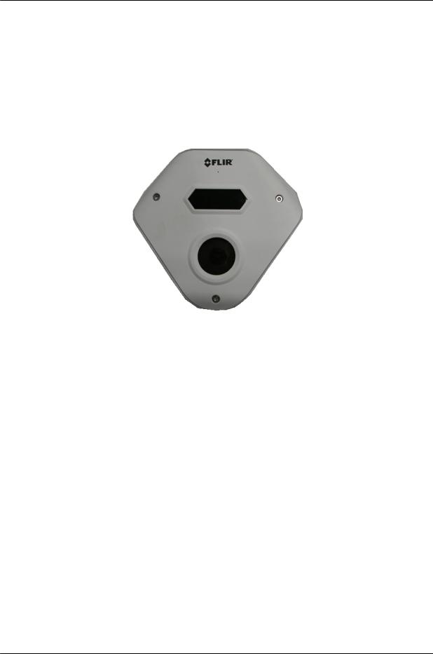
This User and Installation Guide is intended to help you physically install, configure settings for, and operate the CC-3103 indoor/outdoor corner IP camera. The unit is a day/night camera with a 3MP (2048x1536), 1/2.8” sensor, and includes an F1.8, 2.1mm fixed focal lens. The unit offers exceptional lowlight performance. It also includes a built-in microphone, audio out, alarm-in, and alarm-out connections. The camera supports three streams: 2048x1536 (3MP), 1280x960, and 800x600 with H.264 or MJPEG compression (3MP with H.264 only). The camera is powered by an 802.3af Power over Ethernet (PoE) connection. It includes a microSD card slot for storing recordings and snapshots.
CC-3103 Corner Camera
2.1 |
Features |
|
|
3MP 1/2.8” Sony Exmor RS |
Triple stream: 3MP + |
H.264 and MJPEG |
|
CMOS sensor |
1280x960 + 800x600 |
compression |
|
Low-lux mode without IR |
True day/night (ICR) |
Infrared LED illuminator |
|
Digital WDR |
3DNR image noise reduction |
Backlight and highlight |
|
|
|
|
compensation |
Built-in web server |
Supports Internet Explorer, |
HTTP streaming MJPEG |
|
|
|
Edge, Chrome, and Firefox |
|
|
|
browsers |
|
Motion detection event-driven |
Tampering detection and |
Two regions of interest |
|
alarms |
notifications |
|
|
Gamma correction |
White balance |
8 privacy zones |
|
802.1X and SSL/TLS |
SNMP v1/v2c/v3 and SNMP |
Up to 9 users |
|
security protocols |
traps |
|
|
Built-in Mic |
UPnP support |
ONVIF© support |
|
Alarm In/Out |
Powered by 802.3af PoE |
Support for audio-out (on |
|
|
|
|
hardware revision 02.00) |
December 12, 2018 |
CC-3103 User and Installation Guide |
7 |
|
Introduction
3MP 1/2.8” Sony Exmor RS |
Triple stream: 3MP + |
H.264 and MJPEG |
CMOS sensor |
1280x960 + 800x600 |
compression |
Supports up to128GB |
IP66 enclosure with IK10 |
|
microSDXC card |
vandal-proof protection |
|
2.2Package Contents
The unit package contains the following items:
Quantity |
Description |
|
|
|
|
1 |
CC-3103 corner camera |
|
|
|
|
1 |
Bag containing six screws and six plastic anchors |
|
|
|
|
1 |
T20 Torx wrench |
|
|
|
|
2 |
Desiccants |
|
|
|
|
1 |
CC-3103 |
Desiccants User Guide |
|
|
|
1 |
CC-3103 |
Quick Install Guide |
|
|
|
Related Information:
DNA 2.2 User Manual (for more information, see Accessing General Camera Information.)
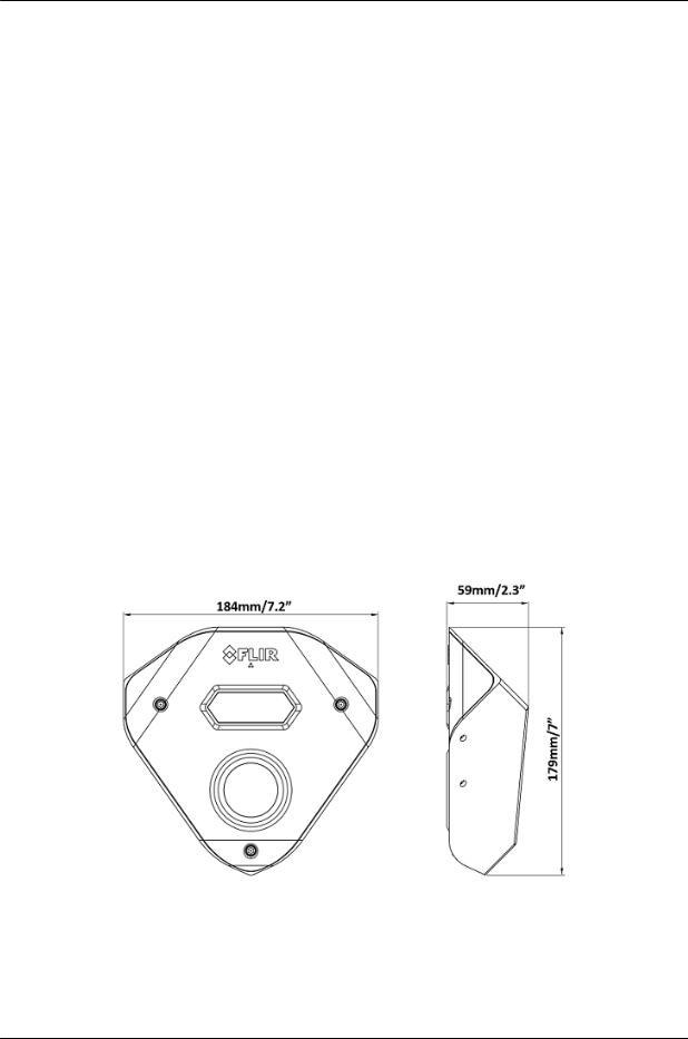
2.3Hardware Description
Following are the CC-3103-01-I fixed focal camera’s dimensions.
CC-3103 Dimensions
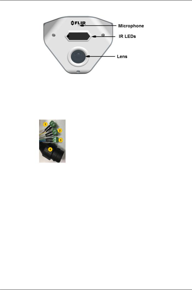
The camera includes a built-in microphone and IR LEDs for true day/night operation.
8 |
CC-3103 User and Installation Guide |
December 12, 2018 |
|
Introduction
CC-3103 Callouts
The CC-3103-01-I camera includes a built-in system cable that includes an RJ-45 Ethernet jack and three
(3) two-wire leads (one audio out, one alarm-in and one alarm-out connection). The cable includes an LED that flashes green to indicate power on and network activity. The LED is not illuminated if there is no network activity.
Cable Legend
Color |
Function |
Purple |
Alarm IN |
Yellow |
Ground |
White |
Alarm OUT |
Grey |
COM |
CC-3103 System Cable |
Audio OUT |
Blue |
|
Green |
Ground |
2.4System Requirements
Item |
Minimum System Requirement |
|
|
Personal Computer |
Intel® Pentium® IV, 2.4GHz or higher with >1GB RAM |
|
Monitor display with minimum 1024 x 768 resolution |
|
(NVIDIA GeForce 6 Series or ATI Mobility Radeon 9500) |
|
|
Operating System |
Windows 7, 8, 8.1, and 10 (all 64-bit versions) |
|
Windows Server 2003, Windows Server 2008 (32-bit version) |
|
|
Web Browser |
Microsoft Internet Explorer 10 and above (32-bit version); Microsoft Edge |
|
38 and above; Chrome v.55 and above; Firefox v.50 and above |
|
|
Network Card |
10Base-T (10 Mbps) or 100Base-TX (100 Mbps) operation |
|
|
December 12, 2018 |
CC-3103 User and Installation Guide |
9 |
|

Introduction
Item |
Minimum System Requirement |
|
|
Viewer |
ActiveX control plug-in for Internet Explorer; MJPEG viewer for Edge, |
|
Chrome, and Firefox |
|
|
10 |
CC-3103 User and Installation Guide |
December 12, 2018 |
|

Installation
3 Installation
This section describes how to install and connect the unit. It includes the following topics:
Pre-Installation Checklist
Powering the Camera
Inserting and Configuring the microSD card
Mounting the Camera
Connecting the Camera to the Network
Resetting the Camera
3.1Pre-Installation Checklist
Before installing the unit, make sure that:
Instructions in the Document Scope and Purpose section are followed.
All related equipment is powered off during the installation.
Use best security practices to design and maintain secured camera access, communications infrastructure, tamper-proof outdoor boxes, etc.
All electrical work must be performed in accordance with local regulatory requirements.
Caution:
To avoid damage from overheating or unit failure, assure that there is sufficient temperature regulation to support the unit’s requirements (cooling/heating). Operating temperature should be kept in the range -40° to 50°C (-40° to 122°F), with no more than 90% non-condensing humidity.
Attention:
Afin d'éviter tout dommage dû à une surchauffe ou toute panne de l'unité, assurez-vous que la régulation de température est suffisante pour répondre aux exigences de l'unité (refroidissement/chauffage). La température de fonctionnement doit être maintenue dans la plage (-40° à 50°C/-40° à 122°F), sans condensation d'humidité supérieur à 90%.
December 12, 2018 |
CC-3103 User and Installation Guide |
11 |
|
Installation
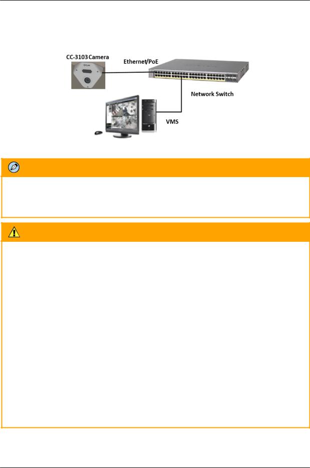
3.2Powering the Camera
The camera is powered by an 802.3af PoE (Class 3) connection over the unit’s network cable.
System Connection
Note:
An ITE PoE injector should be connected only to a PoE network inside a building and not routed outside the building.
Caution:
1.This product must be connected only to a PoE network.
2.The PoE supply’s rated output is 48VDC, 0.2A.
3.If the camera is installed for outdoor use, the PoE supply must be installed with proper weatherproofing.
4.As a Listed Power Unit, the PoE should be marked as “LPS” or “Limited Power Source”.
5.This product shall be installed by a qualified service person. Installation shall conform to all local codes.
Attention:
1.Ce produit doit être connecté uniquement à un réseau PoE.
2.La puissance nominale de l'alimentation PoE est 48VDC, 0.2A.
3.Si la caméra est installée pour une utilisation extérieure, l'alimentation PoE doit être installé avec l'étanchéisation appropriée.
4.Comme une unité d'alimentation «Listed», le PoE doit être marqué comme «LPS» ou «Limited Power Source".
5.Ce produit doit être installé par un technicien qualifié. L'installation doit se conformer à tous les codes locaux.
12 |
CC-3103 User and Installation Guide |
December 12, 2018 |
|

Installation
3.3Inserting and Configuring the microSD Card
A microSD card (not supplied - (Min recommended 4GB, up to 128GB, Class 10)) must be inserted in the camera in order to locally store a snapshot or recording triggered by an event. The microSD card slot is located on a printed circuitboard inside the camera housing. To install a microSD card:
1.After removing the camera's cover, insert a microSDXC card in the card slot.
2.Be sure that a new desiccant is inserted inside the enclosure.
3.Replace the cover and screw the enclosure shut.
4.Verify that the card status is displayed as mounted in the System > Events Handler > SD Card screen.
5.Configure the camera to store snapshots and recordings from the System > Events Source screens.
3.4Mounting the Camera
The CC-3103 camera is designed to be mounted against the ceiling and two walls in the corner of a room for optimal viewing of the scene. The camera enclosure includes screw holes on three sides.
Required items:
1.Electric screwdriver
2.Phillips screwdriver
3.Electric drill
4.Hammer
5.Six plastic screw anchors (supplied)
6.Six screws (supplied)
December 12, 2018 |
CC-3103 User and Installation Guide |
13 |
|
Installation
To mount the camera
1.Mount the camera at the site according to your surveillance requirements. Be sure to have the required accessories and tools available.
2.Remove the protective plastic covering the electronics in the camera body.
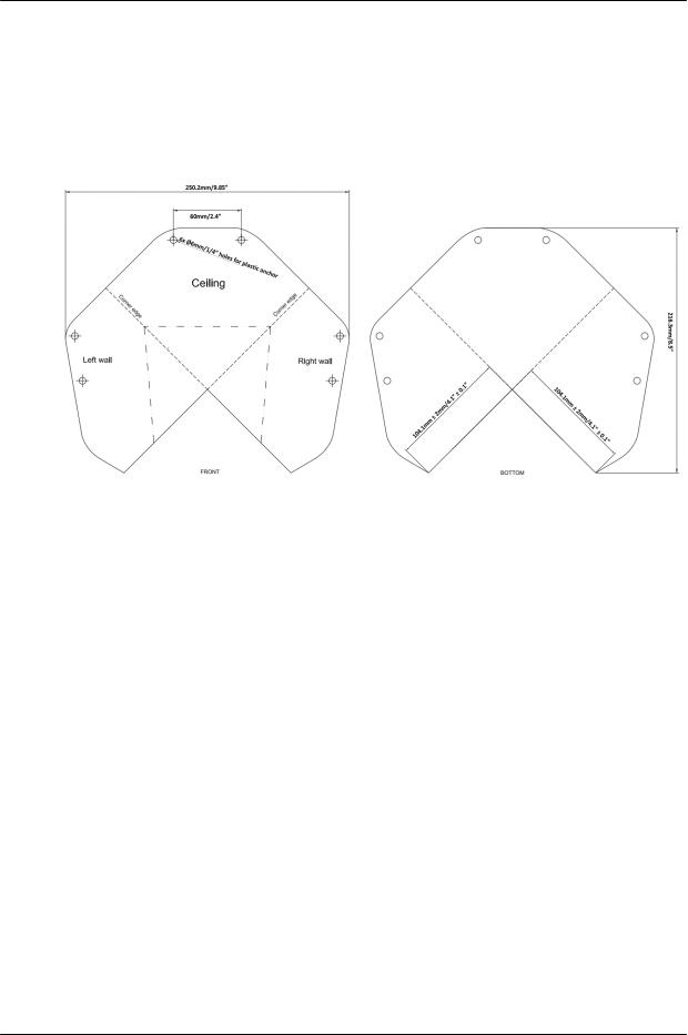
3.Using the provided template, mark the drill locations on the ceiling and wall.
Drill Template
4.Drill a hole in the ceiling to insert the system cable.
5.Drill holes into the surfaces for the screws.
6.Hammer the screw anchors into place.
7.Attach the system cable to the network switch.
8.Align the screw holes on the camera body with the markings on the surface.
9.Using the electric screwdriver, screw the camera body into the surfaces.
10.Verify that you have inserted new dessicant inside the camera body.
11.Replace the protective plastic covering over the camera's electronics.
12.Attach the safety lanyard from the camera body to the camera cover.
13.Using the Torx wrench, screw the camera cover over the camera body.
14 |
CC-3103 User and Installation Guide |
December 12, 2018 |
|
Installation
3.5Resetting the Camera
The camera includes a reset button, which is located on a printed circuit board inside the camera housing,
along with the camera’s microSD card slot.
Camera Reset/MicroSD Cover
To reboot the camera
1.Using the supplied Torx wrench, open the camera enclosure. The reset button and microSD card drive are exposed.
2.Press the reset button for approximately five seconds. The unit reboots.
To restore factory defaults using the reset button
Note: It is recommended to back up configuration prior to resetting the camera in order to keep configuration and settings, which can be re-applied after the factory default.
For more information see: Import Settings
Note: If factory defaulting due to a camera malfunction, it may be beneficial to contact support prior to the default to allow them to better resolve the issue.
1.Press the reset button continuously for 30 seconds. The unit restores factory defaults.
Note:
Remember to insert new desiccant inside the camera enclosure before screwing it shut.
3.6Connecting the Camera to the Network
To view and configure the camera via a LAN, you must attach the camera via the network switch or router to the same subnet (network segment or VLAN) as the computer that manages the unit. If the PC is on a different subnet than the camera, you will not be able to access the camera via a web browser.
If there is a DHCP server on the network, it is recommended to use FLIR’s Discovery Network Assistant (DNA) utility to search for and change the camera’s initial IP address. If there is no DHCP server on the network, the camera will initialize with the default IP (192.168.0.250). You can then use DNA to change its IP address.
December 12, 2018 |
CC-3103 User and Installation Guide |
15 |
|
Installation
3.6.1Configuring Communication Settings
To configure communication settings on the camera
1.Connect the camera to the network on the same VLAN/LAN as the workstation.
2.If the network supports the default, open the DNA utility by running dna.exe which can be downloaded from the FLIR Website - see Accessing General Camera Information.
3.In the DNA application, click the DNA button.
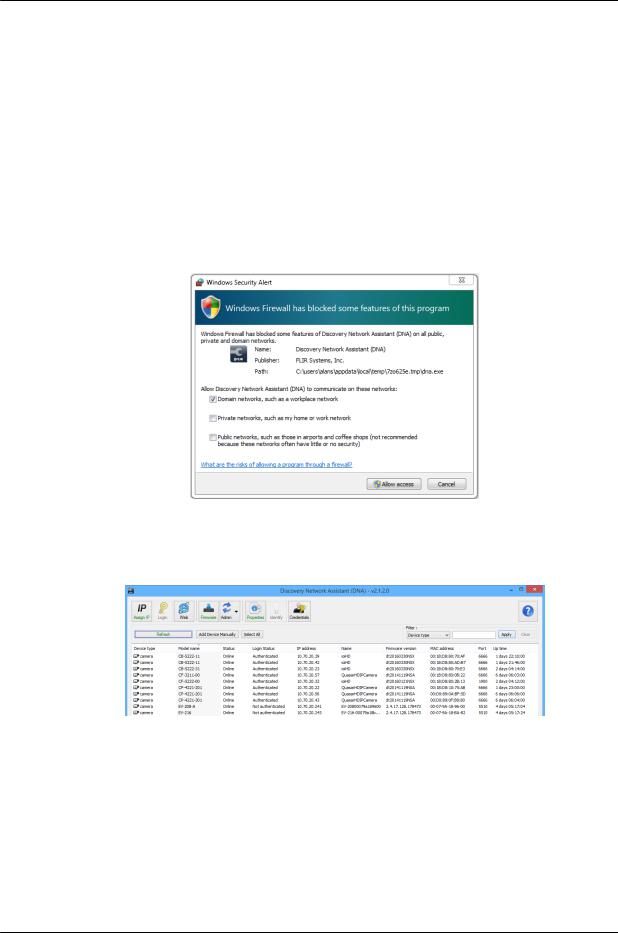
4.If the Windows Firewall is enabled, a security alert window pops up.
5.To continue, click Allow Access. Latitude users should consult the Latitude Installation Instructions on disabling the Windows Firewall.
Windows Firewall Screen
6.Click Assign IP. All the discovered IP devices will be listed in the page, as shown in the figure below. The camera’s default IP Address is automatically supplied by the DHCP server.
Discovered IP Devices
16 |
CC-3103 User and Installation Guide |
December 12, 2018 |
|

Installation
7.Right-click the camera whose network property is to be changed. From the context menu that opens, select Assign IP. The Assign IP dialog is displayed.
DNA Assign IP – Use DHCP Dialog Box
Tip:
Record the camera’s MAC address for future reference.
8.To access DNA, do one of the following:
a.For DHCP (not supported by Latitude):
i.Select Use DHCP. Do not use for Latitude.
ii.Click Update and wait for status.
b.For Static IP (recommended for Latitude users):
DNA Assign IP – Static IP Dialog Box
December 12, 2018 |
CC-3103 User and Installation Guide |
17 |
|
Installation
i.Do not select the Use DHCP checkbox. This is recommended for security purposes and for and Latitude users. In the IP Address, Gateway, and Netmask, enter the respective LAN/VLAN (optional DNS) values.
ii.Click Update and wait for  OK status to be displayed.
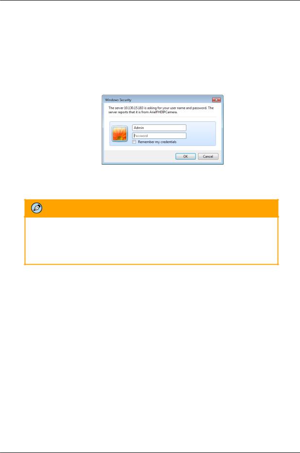
9.Right-click and select Web to directly access the camera via a web browser. The web browser opens on the unit’s Login dialog box.
Login Dialog Box
10. Log into the unit with the default user name Admin and password 1234.
Note:
1.Both the user name and password are case-sensitive.
2.It is strongly advised that administrator’s password be altered for security reasons.
If the User Account Control dialog box opens and requests you to install the install.cab file, click Yes.
If the ActiveX installation is not successful after performing the previous step, in the Internet Explorer Tools > Internet Options > Advanced Security section, select the Allow software to run or install even if the signature is invalid checkbox. Uncheck the checkbox after installing ActiveX. Then click OK.
18 |
CC-3103 User and Installation Guide |
December 12, 2018 |
|

Installation
IE Tools > Internet Options > Advanced Window
If you are using ActiveX, but do not have the Microsoft Visual C++ 2008 Redistributable libraries installed on your PC, the following error message is displayed. In this case, download and install the vcredist_x86.exe file from the Internet, or contact your Network Administrator or FLIR Support.
MS Visual C++ 2008 Redistributable Error Message
11. If a popup message appears for running the ActiveX add-on, click Allow.
Note:
If the password is changed and the Latitude AdminCenter Discovery feature is in use, deselect all other proprietary types. Select Dvtel Ariel Line as the Unit Type so that the new password can be configured in the Discovery > Add Unit Manually setting.
Additionally, you can change the camera’s network properties (either DHCP or Static IP) directly from the camera’s web interface on the System > Network > General screen.
December 12, 2018 |
CC-3103 User and Installation Guide |
19 |
|

Installation
12. Install the web player.
Note:
If you have previously installed a web player application on the PC, you should delete the existing web player from the PC before accessing the camera.
3.6.2Using DNA to Access the Camera
To view and configure the camera via a LAN, you must attach the camera via the network switch or router to the same subnet (network segment or VLAN) as the computer that manages the unit. If the PC is on a different subnet than the camera, you will not be able to access the camera via a web browser.
If there is a DHCP server on the network, it is recommended to use FLIR’s Discovery Network Assistant (DNA) utility to search for and change the camera’s initial IP address.
DNA is a user-friendly utility that is designed to easily discover and configure FLIR Professional Security edge devices on a network. The DNA tool has a simple user interface and does not require any installation. The software is provided as a single, standalone executable. It runs on any PC.
DNA provides a central location for listing all the supported FLIR Professional Security camera models accessible over the network. Once listed, each camera can be right-clicked to access and change the network settings. If the network settings are changed for some reason, a new search will relist the units. The units may then be configured via the web interface.
If FLIR’s Latitude VMS is being used, configure the unit with a static IP address rather than with DHCP. This ensures that the IP address will not automatically change in the future and interfere with configurations and communication.
If there is no DHCP server on the network, the camera will initialize with the default IP (192.168.0.250). You can then use DNA to change its IP address.
Note:
To download the DNA and for detailed guidelines about DNA and its usage, refer to the DNA User Manual. See Accessing General Camera Information.
20 |
CC-3103 User and Installation Guide |
December 12, 2018 |
|
Installation
3.6.3Configuring the Unit’s Initial IP Address
Use the FLIR DNA utility to discover the unit on the network and to set the unit’s initial IP address.
If the camera is located on a network that uses a DHCP server, or is managed by FLIR’s Horizon or Meridian VMS and is configured as a DHCP server, configure the camera with DHCP-enabled. Horizon or Meridian automatically assigns the camera an IP address.
If the camera is located on a network that does not use a DHCP server, or is managed by FLIR’s Latitude VMS, manually enter its IP address in the DNA utility.
Note:
1.It is possible to set the IP address without changing the subnet.
2.The unit and the PC must be physically connected on the same network segment.
To manage the camera using Horizon, Meridian, or on a DHCP-enabled network
1.Download the DNA from the FLIR website: Website Resources
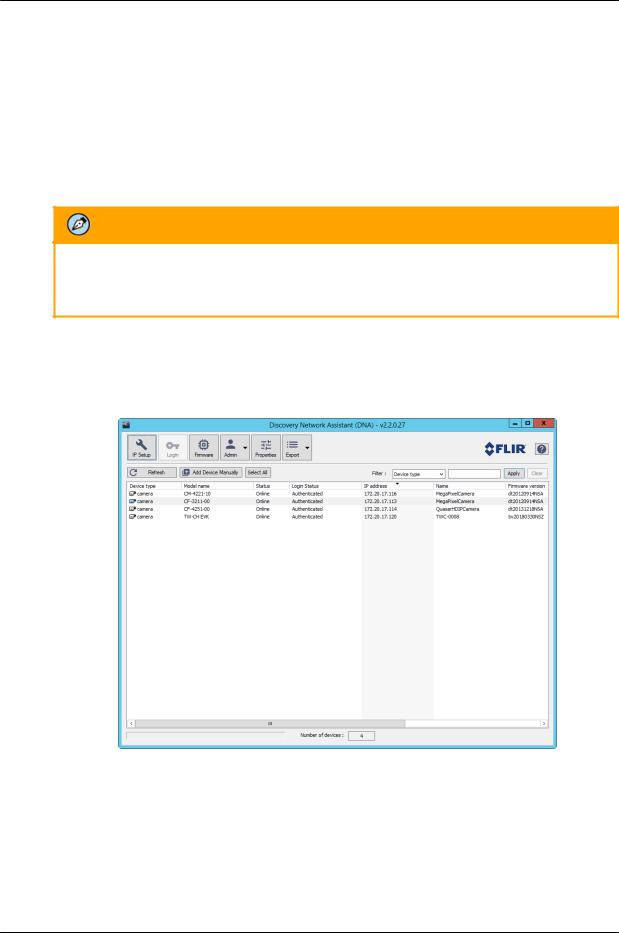
2.Run the dna.exe file by clicking the  icon. The DNA application opens and the device is displayed in the window.
DNA Discovery Window
December 12, 2018 |
CC-3103 User and Installation Guide |
21 |
|
Installation
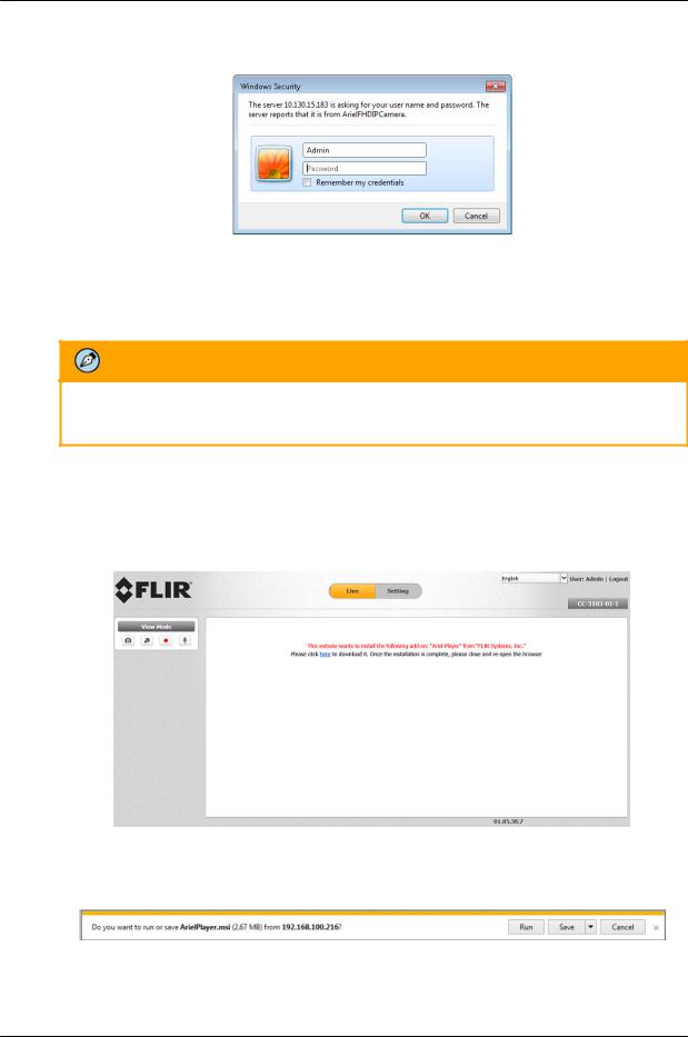
3.Double click on the unit in DNA’s Discover List. The CC-3103 Login window opens.
Login Window
4.If the camera cannot connect to a DHCP server, the unit initializes with the default IP address (192.168.0.250).
5.Enter the default User Name (Admin) and Password (1234).
Note:
The user name and password are case-sensitive.
6.Click Login. The camera’s web interface opens.
If your browser is Edge, Chrome or Firefox, the video is displayed in the Live View window.
If your browser is Internet Explorer, a message is displayed, requesting you to install a plugin.
Web Interface with Internet Explorer Browser
7.Click “here” on the screen to download the Ariel Player plug-in. The Ariel Player plug-in information bar opens.
Run Ariel Player Plug-in Information Bar
22 |
CC-3103 User and Installation Guide |
December 12, 2018 |
|
Installation
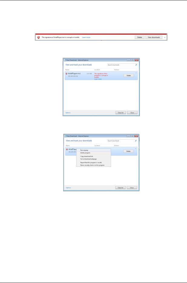
When using Internet Explorer in closed networks, occasionally the browser will not install the Ariel Player on the client PC because it cannot verify the Ariel Player’s digital signature. This may be because the local certificate is out of date, invalid or missing. The following message is displayed:
Corrupt/Invalid Signature
a.Click View downloads. The View Downloads screen opens.
View Downloads Screen
b.Right-click on the ArielPlayer.msi file.
Run Anyway Option
c.Select “Run anyway”. The normal installation process starts.
8.Follow the instructions in Appendix 10.5 for installing the Player. After installing the Player, the Live View is displayed.
December 12, 2018 |
CC-3103 User and Installation Guide |
23 |
|
Installation
To manage the camera using Latitude or on a network with static IP configuration
1.Download the DNA from the FLIR website: Website Resources
2.Run the dna.exe file by clicking the  icon. The DNA application opens and the device is displayed in the DNA Discovery window. See Figure: DNA Discovery Window.
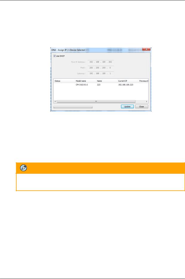
3.Select the unit by right-clicking it. The DNA - Assign IP window is displayed.
DNA Assign IP - Use DHCP Screen
4.Uncheck Use DHCP.
5.Enter the unit’s default IP address (192.168.0.250), Subnet mask, and Gateway IP address in the respective field.
6.Click Update. The unit reboots with the new settings.
7.Click on the unit in DNA’s Discover List. The camera’s Login window opens. See Figure: Login Window.
8.Enter the default User Name (admin) and Password (admin).
Note:
The user name and password are case-sensitive.
9.Click Login. The camera’s web interface opens. See Figure: Web Interface.
10.Click the on-screen message to install the Ariel Player plug-in. The Ariel Player Plug-in message is displayed. See Figure: Ariel Player Plug-in Download Information Bar.
24 |
CC-3103 User and Installation Guide |
December 12, 2018 |
|
Loading...