

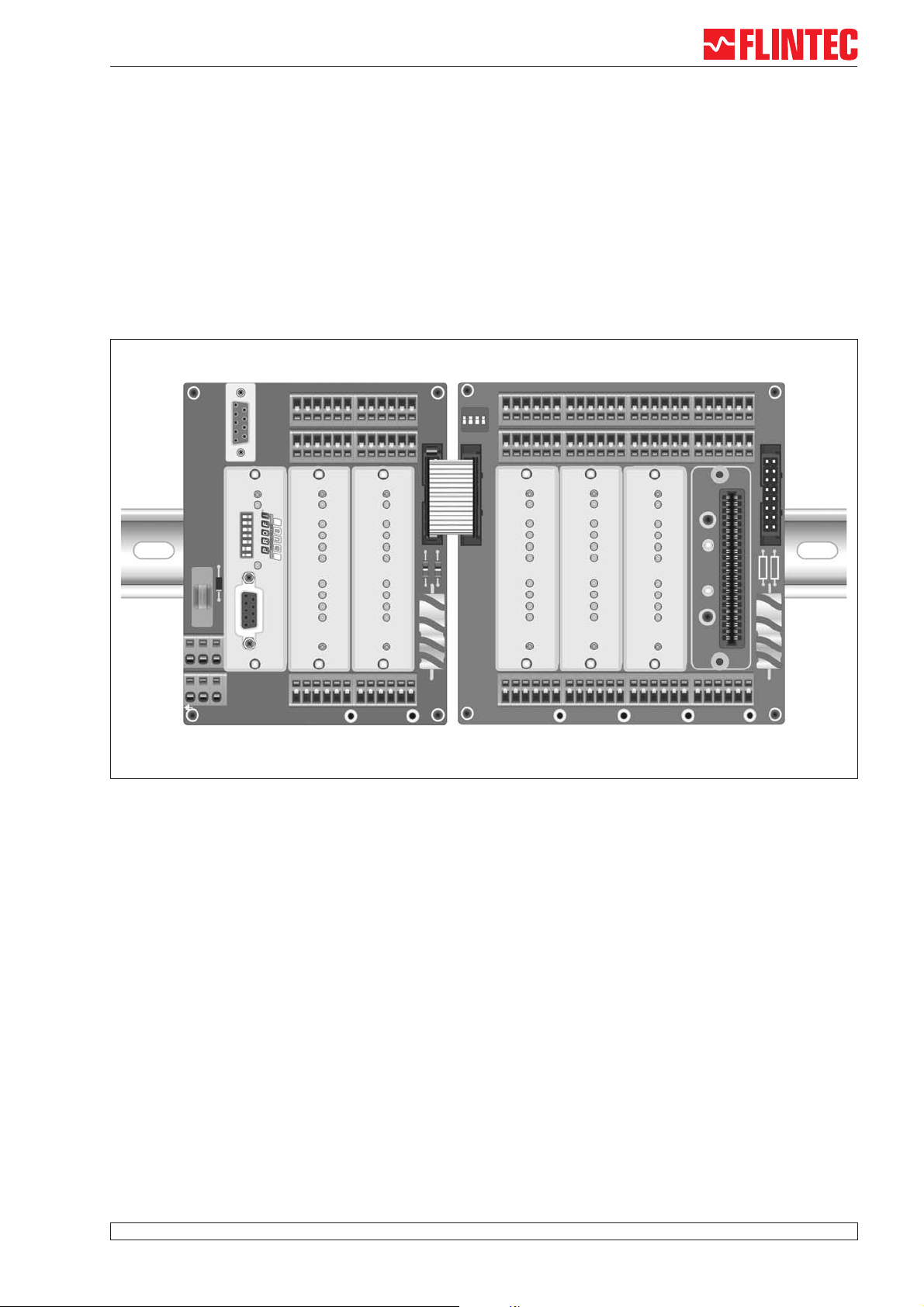
MCS-64
(Multi Channel System for Process Industry)
Manual MCS-6 with Modbus on Ethernet
FUSE
5X20
0
Y
5
V+
1
9
6
5
PWR
PGM 86.1
Com
6
5
4
3
2
1
PB Adresse
0
Act
Profibus Connector
FLINTEC
www.flintec.com
Example of MCS-64 with 5 channels and Profibus-Gateway
C0123C C0123C
PWR
Com
In 0
In 1
In 2
In 3
Out 0
Out 1
Out 2
Out 3
Err
Sig+
Sen+
Exc+
PWR
Com
LDM 88.1
Exc-
Sen-
Sig-
LDM 88.1
In 0
In 1
In 2
In 3
Out 0
Out 1
Out 2
Out 3
Err
Exc-
Sen-
Sig-
Sig+
Sen+
Exc+
Logic out
Logic in
BC
470uF
+HP
Load
Cells
FLINTEC Fl112081 B16
Mt1
ON DIP
1234
FLINTECFl112081 B16
FLINTEC
www.flintec.com
Exc+
Mt27
PWR
Com
In 0
In 1
In 2
In 3
Out 0
Out 1
Out 2
Out 3
Err
Sen+
C0123CC0123CC0123C C0123C
Mt2
Logic out
Logic in
T6
J14
R1
R2
BC
470uF
+HP
LDM 88.1
PWR
Com
In 0
In 1
In 2
In 3
Out 0
Out 1
Out 2
Out 3
Err
LDM 88.1
PWR
Com
In 0
In 1
In 2
In 3
Out 0
Out 1
Out 2
Out 3
Err
LDM 88.1
T26
Load
Cells
Mt28
Exc-
Sen-
Sig-
Sig+
Sen+
Exc+
Exc-
Sen-
Sig-
Sig+
Sen+
Exc+
Exc-
Sen-
Sig-
Sig+
Sen+
Exc+
Exc-
Sen-
Sig-
Sig+
Document no. G165-Rev1-GB
www.flintec.com
Manual MCS-64 Page 1

Components of MCS-64 in overview
Base Board
MB 89.1
LDM 88.1
CGM 85,1
Load Cell
#1
Load Cell
#2
Load Cell
#64
LDM 88.1
#1
LDM 88.1
#2
RS485 - Bus
LDM 88.1
#64
RS 232
Service-Port
Gateway
- Profibus (PGM 68.1)
- CANopen (CGM 85.1)
- Ethernet (EGM 87.1)
Components of MCS-64
All boards have the same technical features:
Spring clips for load cell terminals in 6-wire-technique
•
• 4 DI’s via spring clip terminal blocks
•
4 DO’s via spring clip terminal blocks
Fieldbus
Extension Boards
MB 89.2
MB 89.3
MB 89.4
PGM 86.1
MB 89.1
EGM 87,1
•
Slot for one Gateway CGM 85.1 / PGM 86.1 / EGM 87.1
•
2 Slots for weighing processor LDM 88.1
•
RS 232 Service port
Extension Boards MB 89.2/.3/.4
•
2/4/8 Slots for weighing processor LDM 88.1
MB 89.2
MB 89.3
Base Board MB 89.1
Dim 104 x 135 mm
MB 89.4
Dim 79 x 135 mm
Dim 129 x 135 mm
Dimensions 229 x 135 mm
Page 2 Manual MCS-64 Ethernet
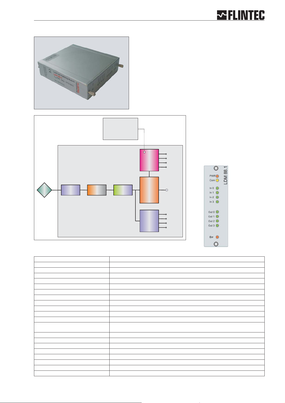
Weighing Processor LDM 88.1
Remote Control Output
Start Filling Cycle
Trigger Signal
The digital weighing processor LDM 88.1 is a load cell
digitizing unit for precise measuring of loads in motion.
± 18 bit resolution (±260 000 d)
•
Excitation5VDC/50mA
•
2 400 Measurements/s internal,
•
600 Measurements/s external
mV/V calibration
•
4 DI’s
•
4DO’s
•
RS 485 bus, 115.2 kBaud
•
Digital Filter (FIR and IIR)
•
for static or dynamic weighing
•
processes
3 Firmware versions
•
LDM 88.1
Digital
Load Cell
Low-Pass
Filter
ADC
Digital Filter
IIR- / FIR
Input
1 ... 4
- Net
- Gros
- Average
- Dose
Digital
Output /
Setpoint
1 ... 4
binary format
RS 485 / 230 kBaud
LDM 88.1
LDM 88.1 Specifications
Linearity < 0.002 % FS
Excitation 5 V DC, load cells 100-2 000 Ohm, 6 wire technique
Analogue input range ±2.2 mV/V (bipolar)
Minimum input per vsi 0.05 μV per interval non approved
Resolution ±260 000 counts , ±18-Bit-A/D convertor
Conversion rate 2400 measurements per second intern
Digital Filter FIR Filter 2.5 ... 19.7 Hz or IIR Filter 0.25 ... 18 Hz; programmable in 8 steps each
Calibration software calibration and set up
Computer interface intern RS485/RS422, full duplex, 115 200 Baud, bus capability up to 64 devices
Weighing functions zero, gross, tare, net, filter etc.
Inputs 4 opto-isolated inputs, 10 ... 30 V DC max. 3 mA
Outputs 4 OC outputs, < 35 V DC, 500 mA
Temperature effects on zero 5 ppm/°K typ.; max. < 10 ppm/°K
Temperature range –10 °C to +50 °C (operating); –30 °C to +80 °C (storage)
Enclosure Aluminium, protection IP40
Dimensions 80 x 23 x 100 mm, with two M3 fixing screws for mounting on boards MB89.1/2/3/4
Power supply 12 ... 24 V DC ±10 %, < 60 mA,(reversed voltage, burst and ESD protected)
Power consumption 1,5 W max.
EMC CE 73/23/EEC; 93/98/EEC and 89/336/EEC
Computer interface via Service Port MB 89.1 RS232C, 115 200 Baud
Vibration withstands 1.0 G operational; 2.5 G non-operational
on span 4 ppm/°K typ.; max. < 8 ppm/°K
Manual MCS-64 Ethernet Page 3

Contents
Part A: Modbus on Ethernet.........................................................................................pages 6 - 13
Part B: Commands......................................................................................................pages 14 - 35
Part C: MCS-64 Components and Configuration........................................................pages 36 - 45
Introduction...........................................................................................................................6
1.
1.1. Identification and Scope ................................................................................................6
1.2. Purpose .........................................................................................................................6
2. System Design......................................................................................................................6
2.1 General..........................................................................................................................6
2.2 Backplane handling.......................................................................................................6
2.3 Ethernet Gateway..........................................................................................................7
2.3.1 IP Settings.................................................................................................................7
2.3.2 The Modbus port .......................................................................................................7
2.3.3 The ASCII entry port..................................................................................................7
3 Ethernet Gateway Profile.....................................................................................................8
3.1 The Modbus Objects .....................................................................................................8
3.2 Communication Profile ..................................................................................................8
4 Modbus Mapping..................................................................................................................9
4.1 Modbus Register Map Overview ...................................................................................9
4.1.1 Gateway Register Map..............................................................................................9
4.1.2 LDM Register Map...................................................................................................10
5 COMMANDS........................................................................................................................14
5.1 System diagnosis – ID, IV, IS......................................................................................15
5.2 Calibration Commands – CE, CM, CI, DS, DP, CZ, CG AZ, AG, ZT, FD, CS.............16
5.3 Motion detection Commands – NR, NT.......................................................................20
5.4 Filter setting Commands – FM, FL, UR.......................................................................21
5.5 Set Zero/Tare and Reset Zero/Tare Commands – SZ, RZ, ST, RT............................23
5.6 Output Commands – GG, GN, GT, GS.......................................................................25
5.7 Setpoint Commands - Sn, Hn, An ...............................................................................26
5.8 Trigger Commands – SD, MT, GA, TE, TR, TL...........................................................28
5.9 Trigger Special Commands– RW, TT, TS, DT, TW, TI, HT.........................................31
5.10 Save calibration, setup and setpoint parameters Commands – CS, WP, SS .............34
5.11 Filling Commands – PD1 to PD21, DI, SC, AC, GD, DT, SD......................................35
5.12 Loss in Weight Commands – PL1 to PL5, LC, LI, GF, GR, GM, SL...........................35
5.13 Speed Estimation Multi-Channel System MCS-64......................................................35
Page 4 Manual MSC-64: Modbus on Ethernet

6 MCS-64 Components and Configuration..........................................................................36
6.1 Base Board MB 89.1 for 1 Gateway and 2 LDM 88.x..................................................36
6.2 Extension Board MB 89.2 for 2 LDM 88.x...................................................................37
6.3 Extension Board MB 89.3 for 4 LDM 88.x...................................................................38
6.4 Extension Board MB 89.4 for 8 LDM 88.x...................................................................39
6.5 Address setup guide extension boards for 1 – 16 channels........................................40
6.6 Address setup guide extension boards for up to 32 channels.....................................41
6.7 Example Check Weigher Wiring ..................................................................................42
6.8 Example Liquid Filling Wiring ......................................................................................43
6.9 LDM 88.1 – Digital Input / Digital Output -...................................................................44
6.10 Firmware Versions.......................................................................................................45
6.11 DOP software for Windows 2000/XP...........................................................................45
Manual MCS-64: Modbus on Ethernet
Page 5

1. INTRODUCTION
1.1. Identification and Scope
This document describes the system design for the Modbus on Ethernet (EGM 87.1) and up to
64 Load Cell Digitizing Modules (LDM88.x) using the Flintec backplane system. It describes the
functionality of the backplane, the protocol used on the backplane and the Modbus mapping used
to access the LDM88 modules via the EGM87 Gateway.
1.2. Purpose
The purpose of this document is to specify functionality and performance of the Gateway and the
Load Cell Digitizing Modules (LDM88) with the available firmware versions (standard 88.183,
filling 88.184, loss in weight 88.185).
2. SYSTEM DESIGN
2.1 General
This software connects an Ethernet network to the local backplane modules. The Gateway
transports commands and responses from and to the Ethernet.
Ethernet
Ethernet
Ethernet
ADAPTOR
ADAPTOR
LDM an d other IO
Up to 64 modules per backplane
BACKPLANE
Figure 1- ETHERNET Gateway in context
2.2 Backplane handling
The Gateway translates Modbus requests to local backplane requests and local backplane
responses to Modbus responses. The Modbus is currently fixed to port 502 using an UDP/IP
connection. Multiple register access through the Ethernet will produce multiple accesses on the
local backplane. The PLC response timeout must allow 3.125 ms for each register access
required.
However reading registers 2000 or 2004 will cache register 2060 also allowing the PLC to
acquire the corresponding qualifier to the weight values.
Page 6 Manual MSC-64: Modbus on Ethernet
2.3 Ethernet Gateway
The Ethernet Gateway is using a 10/100baseT on RJ45 connection (IEEE 802.3u standard).
The Gateway is essentially a server waiting for a node to connect to one of its services.
Application stacks:
Modbus Application Layer Setup
Port 502 Port 502 Port 23
MBAP MBAP TCP UDP TCP
IP IP IP
802.3 802.3 802.3
System stacks:
(echo / ping) (Dynamic IP addr.) (Address Resolution)
ICMP DHCP IP IP ARP
802.3 802.3 802.3
2.3.1 IP Settings
The IP address is set by connecting a terminal program (e.g. HyperTerm) to the DB9 service port
on the MB 89.1 Base board. After the system is powered up it is possible to communicate with
the Ethernet Gateway Module (EGM). After openening the gateway with command "OP 64" it is
possible to set and/or examine the gateway settings with the address command:
Command
op64 opens serial communication to the gateway
ai 192.168.1.29 sets the gateway’s IP address to “192.168.1.29”
ai selects a dynamic IP address (DHCP) for the gateway
a reads current MAC address and IP address of the gateway
Example:
op64
OK
a
mac=00:50:C2:70:50:62
ip= DHCP
2.3.2 The Modbus port
[Port 502, TCP/IP (Modbus) or UDP/IP (Modbus)]
The Modbus is a simple Master-Slave connection; the master asks and the slave answers.
Modbus over TCP or UDP is just another way of transporting Modbus communication. One of the
registers will be used to define a streaming port. When a client connects to this user-defined port
the gateway will scan the backplane and transmit the LDM data on a regular basis.
See Chapter 3 “Ethernet Gateway Profile” below.
2.3.3 The ASCII entry port
[Port 23, TCP/IP (Telnet)]
This entry is for simple setup and diagnostic use. It works as if you were connected to the service
port except it goes through the Ethernet. The HyperTerm program in Windows can access the
gateway in this manner. Refer to LDM 88.1 commands, see chapter 5.
Manual MCS-64: Modbus on Ethernet
Page 7

3 ETHERNET GATEWAY PROFILE
3.1 The Modbus Objects
All parameters and result data can be accessed in this way. Please note that many of the
registers in the 2000 – 20FF range require a local backplane access cycle per register. Reading
multiple registers in this range may produce a very long response time.
Below is the preliminary Modbus Map.
3.2 Communication Profile
The parameters which are critical for communication are determined in the communication
profile. This includes the data for manufacturer's product nomenclature, for identification, or the
parameters for object mapping.
Abbreviations used in the tables:
R = read only
R/W = read / write
W = write only (read will not be regarded as an error, but returns undefined results)
UI16 = Unsigned16 (single register)
UI32 = Unsigned32 (register pair)
Int16 = Signed16 (single register)
Int32 = Signed32 (register pair)
Float = 32 bit IEEE754 floating point (register pair)
Page 8 Manual MSC-64: Modbus on Ethernet
4 MODBUS MAPPING
The MBAP header “Unit Identifier” field is used to select a module in the backplane. Address 0
(zero) is reserved for broadcast. Address 1 to 64 is then used for direct communication with any
LDM in the backplane using registers in the range 2000-2FFF (hex). Access to the gateway
should use address 0xFF (255 dec) and registers in the range 3000-3FFF(hex).
Currently implemented function codes are: Access
03 Read Holding Registers
04 Read Input Registers
06 Write Single Register
16 Write Multiple Registers
Used exception codes are: Meaning
01 Illegal or unkown function code
02 Illegal data address or no response from LDM
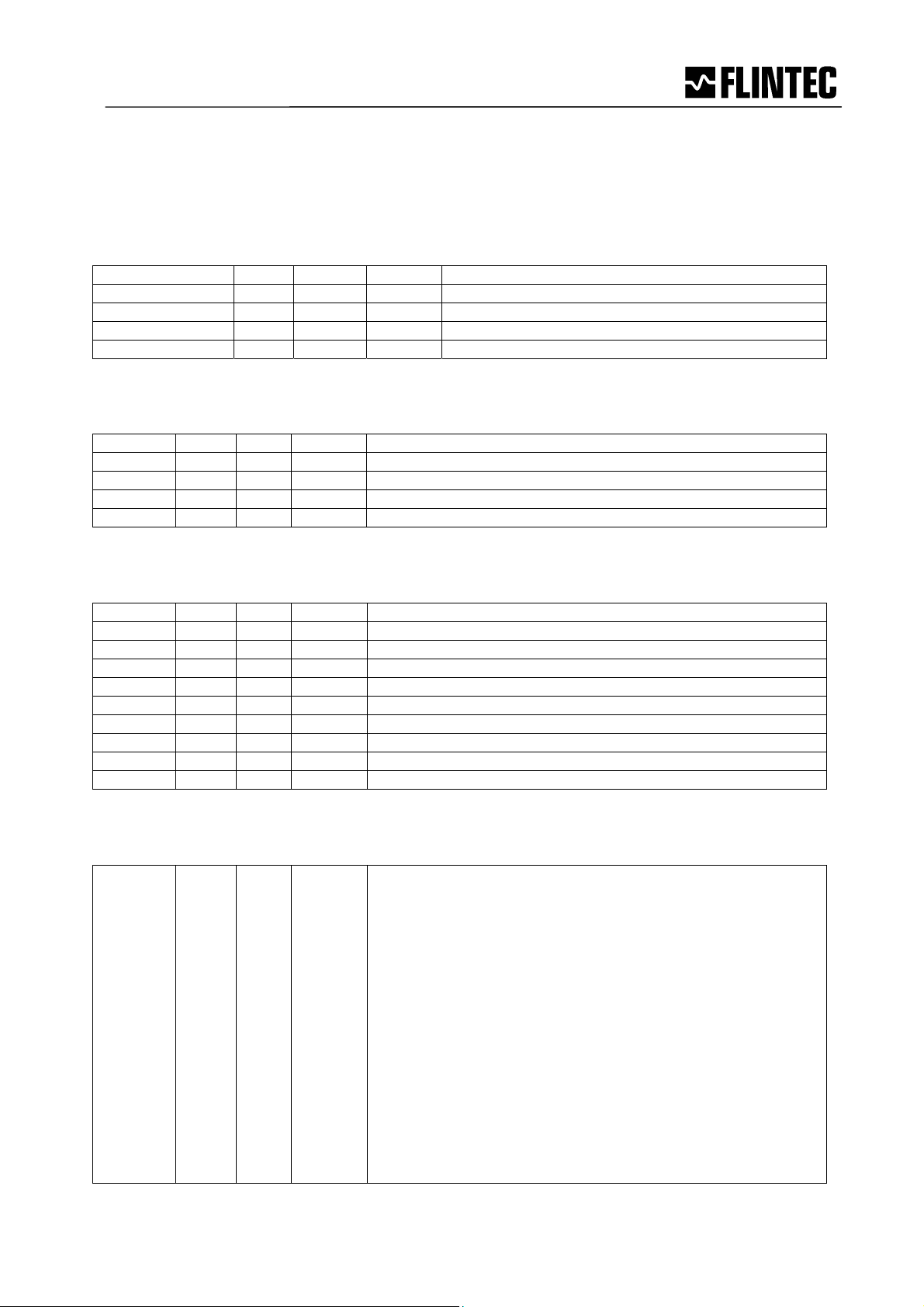
4.1 Modbus Register Map Overview
Register Type Size Access Function
2000 – 2FFF Selected LDM
3000 – 30FF Gateway
4.1.1 Gateway Register Map
Register Type Size Access Function
3000 Int16 1 R/W LDM selector [0..63]
3001 Int16 1 R/W LDM multiple register selector.
3002 Int16 1 R/W LDM multiple register mode
3003 – 300F - - (reserved)
3005 Int16 1 R/W Auto-Scan Control/Status
3006 Int16 1 R/W Auto-Scan Port (IP port no.)
3007 Int32 2 R/W Auto-Scan Interval (ms)
3009 – 30FF (reserved)
3100 – 31FF R/W Multiple register access across multiple LDM modules.
3200 – 32FF Float 2+2+1 R Multiple read of LDM packets
3300 – 33FF Integer 2+2+1 R Multiple read of LDM packets
Bit:
15 10 9 2 1
+------------+--------+-----+
| Last scan | unused | R/S |
+------------+--------+-----+
Manual MCS-64: Modbus on Ethernet
Page 9
4.1.2 LDM Register Map
The register map for each LDM.
LDM overview
Register Type Size Access Function
2000 – 201F Float 08 * 2 R/W Data in Float Format
2020 – 205F Int32 16 * 2 R/W Data in Integer Format
2060 – 207F Int16 08 * 1 RW Control/Status functions
2080 – 20FF (reserved)
2100 – 2FFF - - R/W Parameter pages
Data in Float Format
Register Type Size Access Data in Float Format
2000 Float 2 R Gross weight
2002 Float 2 R Net Weight
2004 Float 2 R/W Tare
2006 Float 2 R Dosed weight
2008 Float 2 R Average weight
Data in Integer Format
Register Type Size Access Data in Integer Format
2020 Int32 2 R Gross weight
2022 Int32 2 R Net Weight
2024 Int32 2 R/W Tare
2026 Int32 2 R Dosed weight
2028 Int32 2 R Average weight
202A Int32 2 R A/D sample
202C Int32 2 R Device ID
202E Int32 2 R FW Version
2030 Int32 2 R Device Status
2032 Int32 2 R ADC Reference
Control/Status Functions
Register Type Size Access Control/Status functions
2060 Int16 1 R Measurement Qualifier Values:
$0001 - Under range
$0002 - Over range
$0004 - Not within Zero range (not yet implemented, zero)
$0008 - Exactly zero
$0010 - No motion, still stand, steady state
$0020 - Tare set
$0040 - Preset tare (0=tare is measured, 1=tare is set by user)
$0080 - Invalid weighing (wire-break, A/D ref. out of range)
$0100 - Set-point 0 (source>limit)
$0200 - Set-point 1
$0400 - Set-point 2
$0800 - Set-point 3
$1000 - Filling in progress
$2000 - Filling has completed
$4000 - Average ready
$8000 - Cold start
Page 10 Manual MSC-64: Modbus on Ethernet

2061 Int16 1 R/W Bit commands. Functions regardless of the setting of the LDM
selector register.
Bit 1: Reset Zero (RZ)
Bit 2: Set Zero (SZ)
Bit 3: Reset Tare (RT)
Bit 4: Set Tare (ST)
Bit 5 – 7: unused
Bit 8 –15: LDM#
Write a “1” to activate function, reads as “1” until command done
2062 Int16 1 R/W Trigger: Functions regardless of the setting of the LDM selector
register.
Write the LDM number to trig LDM;
Write the LDM number + 80h(128 dec) to cancel measurements
(LDM 88.183 only)
2063 Int16 1 R/W Parameter page select. Valid values= [0..4].
General parameter values
Calibration parameter values
Filling parameter values
Check weigher parameter values
Mass flow parameter values
2064 Int16 1 R/W TAC access, see calibration page.
2065 Int16 1 R/W START / ABORT filling process.
Writing a Non-zero value starts filling process.
Writing a zero ABORTS filling process.
2066 Int16 1 R/W EEPROM functions:
Bit 1: Save analogue parameters (AS)
Bit 2: Save calibration (CS); TAC protected
Bit 3: Save general setup parameters (WP)
Bit 4: Save dosing parameters (SD)
Bit 5: Save setpoint parameters (SS)
Bit 6 –14: unused
Bit 15: Factory default; TAC protected
2067 Int16 1 R/W Set-point select [0..3]
2068 Int32 2 R/W Set-point source
206A Int32 2 R/W Set-point hysteresis
206C Int32 2 R/W Set-point Value
206E Int16 1 R Read the dose info:
Bit value Meaning
$0001 Coarse valve open
$0002 Fine valve open
$0004 Dose program running
$0008 Not used
$0010 Not used
$0020 Not used
$0040 Tare out of range – no filling in this cycle
$0080 Zero out of range
$FF00 The High byte has the following interpretation:
00= Idle
01= Waiting for trigger(2
nd
trigger)
02= Bottle on, calculating tare
03= Pre-fill
04= Main Filling
05= Fine Filling
06= In-flight delay
07= Post fill calculations
08= Post Filling
Manual MCS-64: Modbus on Ethernet
Page 11

Page 0 – General Parameter Values
Register Type Size Access General parameter values
2100 Int32 2 R/W Analog action
2102 Int32 2 R/W Analog high
2104 Int32 2 R/W Analog low
2106 Int32 2 R/W Filter setting
2108 Int32 2 R/W Filter Factor
210A Int32 2 R/W Output status
210C Int32 2 R/W Input mask
210E Int32 2 R/W Measuring Time
2110 Int32 2 R/W Filter mode
2112 Int32 2 R/W No-motion range
2114 Int32 2 R/W No-motion time
2116 Int32 2 R/W Output mask
2118 Int32 2 R/W Tare
211A Int32 2 R/W Start Delay
211C Int32 2 R/W Trigger Edge
211E Int32 2 R/W Trigger Level
2120 Int32 2 R/W Update rate
2122 Int32 2 R/W Zerotrack (TAC protected)
2124 Int32 2 R/W dtime
Page 1 – Calibration Parameter Values
Register Type Size Access Calibration parameter values
2200 Int32 2 R/W Absolute gain calibrate (32 bit Integer)
2202 Int32 2 R/W Absolute zero calibrate (TAC protected)
2204 Int32 2 R/W Calibrate enable
2206 Int32 2 R/W Calibrate gain (TAC protected)
2208 Int32 2 R/W Set calibration point B
220A Int32 2 R/W Set calibration point A
220C Int32 2 R/W Calibrate max (TAC protected)
220E Int32 2 R/W Calibrate min (TAC protected)
2210 Int32 2 R/W Calibrate save (TAC protected)
2212 Int32 2 R/W Calibrate zero (TAC protected)
2214 Int32 2 R/W Decimal point (TAC protected)
2216 Int32 2 R/W Display step size (TAC protect)
Page 2 - Filing Parameter Values
Register Type Size Access Filling parameter values
2300 Int32 2 R/W Pre-fill mode
2302 Int32 2 R/W Correction factor for in-flight value
2304 Int32 2 R/W Zero Check Time
2306 Int32 2 R/W Tare delay
2308 Int32 2 R/W Tare Average Time
230A Int32 2 R/W Delay after pre-fill
230C Int32 2 R/W Blanking time
230E Int32 2 R/W In-flight delay time
2310 Int32 2 R/W Filling Weight Average Time
2312 Int32 2 R/W Zero tolerance
2314 Int32 2 R/W Tare reference
2316 Int32 2 R/W Tare tolerance
2318 Int32 2 R/W Pre-fill level
231A Int32 2 R/W Fine-fill weight
231C Int32 2 R/W Filling weight
231E Int32 2 R/W In-flight value
Page 12 Manual MSC-64: Modbus on Ethernet

Register Type Size Access Filling parameter values
2320 Int32 2 R/W Secondary pre-fill level
2322 Int32 2 R/W Timeout value in milliseconds
2324 Int32 2 R/W Underweight post-fill time
2326 Int32 2 R/W Tare interval
2328 Int32 2 R/W Bag Rupture Blanking
Page 3 – Check Weigher Parameter Values
Register Type Size Access Checkweigher parameter values
2400 Int32 2 R/W Trigger Level
2402 Int32 2 R/W Trigger Edge
2404 Int32 2 R/W ReTrigWindow
2406 Int32 2 R/W ReTrigTime
2408 Int32 2 R/W HoldTime
240A Int32 2 R/W TareWindow
240C Int32 2 R/W TareTime
240E Int32 2 R/W ReTrigStop
2410 Int32 2 R/W Measuring time
2412 Int32 2 R/W Start delay
2414 Int32 2 R/W dTime
Page 4 - Mass Flow Parameter Values
Register Type Size Access Mass Flow parameter values
2500 Int32 2 R/W Decimal Point
2502 Int32 2 R/W Scale values
d/sec d/min d/hour
x1 0 1 2
x1.000 3 4 5
x1.000.000 6 7 8
2504 Int32 2 R/W dTime
2506 Int32 2 R/W dWeight
2508 Int32 2 R/W Delay after Refill
Page 5 - Mass Flow Control Values
Register Type Size Access Mass Flow parameter values
2600 Int16 2 R/W Flow Control
2601 Int16 2 R/W Flow Status
Page 6 - Mass Flow Results
Register Type Size Access Mass Flow parameter values
2700 Float 2 R Mass Flow Value
2702 Float 2 R Mass Flow Trend
2704 Float 2 R Total Mass
Manual MCS-64: Modbus on Ethernet
Page 13

Part B
5 COMMANDS
These pages describe the ASCII commands as they must be used by the DOP software. For
each command the corresponding Modbus register and data types are shown in brackets [ ]
for reference.
5.1
System diagnosis – ID, IV, IS......................................................................................15
5.2 Calibration Commands – CE, CM, CI, DS, DP, CZ, CG AZ, AG, ZT, FD, CS.............16
5.3 Motion detection Commands – NR, NT.......................................................................20
5.4 Filter setting Commands – FM, FL, UR.......................................................................21
5.5 Set Zero/Tare and Reset Zero/Tare Commands – SZ, RZ, ST, RT............................23
5.6 Output Commands – GG, GN, GT, GS.......................................................................25
5.7 Setpoint Commands - Sn, Hn, An ...............................................................................26
5.8 Trigger Commands – SD, MT, GA, TE, TR, TL...........................................................28
5.9 Trigger Special Commands– RW, TT, TS, DT, TW, TI, HT.........................................31
5.10 Save calibration, setup and setpoint parameters Commands – CS, WP, SS .............34
5.11 Filling Commands – PD1 to PD21, DI, SC, AC, GD, DT, SD......................................35
5.12 Loss in Weight Commands – PL1 to PL5, LC, LI, GF, GR, GM, SL...........................35
5.13 Speed Estimation Multi-Channel System MCS-64......................................................35
Page 14 Manual MSC-64: Modbus on Ethernet
 Loading...