

Load Cell Digitizing Unit
Type LDU 78.1
TECHNICAL MANUAL
Firmware Version 78.183.v.2.50 or higher
Hardware Version 78.101.5.v.3.00
Document No. G119 Rev12 GB
Flintec GmbH
Bemannsbruch 9
74909 Meckesheim
GERMANY
www.flintec.com

Table of Contents:
1. Safety Instructions .................................................................................................................................... 4
2. Declaration of Conformity ........................................................................................................................ 5
3. Introduction and Specifications ............................................................................................................... 6
4. Communications and Getting started ..................................................................................................... 7
4.1. Serial Interface ......................................................................................................................................... 7
4.2. Command Language ................................................................................................................................ 7
4.3. Baud Rate / Device Address .................................................................................................................... 8
4.4. Getting Started ......................................................................................................................................... 8
5. Hardware and Wiring ................................................................................................................................. 9
5.1. Wiring ....................................................................................................................................................... 9
5.2. With Unit Adapter UA 77.1 (RS232) ........................................................................................................ 9
5.3. With Unit Adapter UA 73.2 (RS422 / RS485 Full-/Half-Duplex) .............................................................. 9
5.4. Terminal Configuration ........................................................................................................................... 10
5.5. Load Cell Connection ............................................................................................................................. 10
6. Calibration and Calibration Sequence ................................................................................................... 11
7. Commands – Overview ........................................................................................................................... 12
8. Commands Description .......................................................................................................................... 14
8.1. System Diagnosis Commands – ID, IV, IS, SR, RS .............................................................................. 14
8.1.1. ID Get Device Identity ................................................................................................................................... 14
8.1.2. IV Get Firmware Version ............................................................................................................................... 14
8.1.3. IS Get Device Status ..................................................................................................................................... 14
8.1.4. SR Reset LDU XX.X Firmware ....................................................................................................................... 14
8.1.5. RS Read Serial Number ................................................................................................................................. 14
8.2. Calibration Commands – CE, CM n, CI, MR, DS, DP, CZ, CG, ZT, FD, IZ, ZR, ZI, WT, TM, CS ......... 15
8.2.1. CE Read TAC* Counter / Open Calibration Sequence .................................................................................. 15
8.2.2. CM n Set Maximum Output Value .................................................................................................................. 15
8.2.3. CI Set Minimum Output Value ....................................................................................................................... 15
8.2.4. MR Set Multi-range / Multi-interval ................................................................................................................. 15
8.2.5. DS Set Display Step Size ............................................................................................................................... 16
8.2.6. DP Set Decimal Point Position ....................................................................................................................... 16
8.2.7. CZ Set Calibration Zero Point ........................................................................................................................ 16
8.2.8. CG Set Calibration Gain (Span) ..................................................................................................................... 16
8.2.9. ZT Enable / Disable Zero Tracking ................................................................................................................. 16
8.2.10. FD Reset to Factory Default Settings ............................................................................................................. 17
8.2.11. IZ Correction of System Zero ........................................................................................................................ 17
8.2.12. ZR Zero Range .............................................................................................................................................. 17
8.2.13. ZI Initial Zero Range ...................................................................................................................................... 17
8.2.14. WT Warm-up time .......................................................................................................................................... 17
8.2.15. TM Tare mode ................................................................................................................................................ 17
8.2.16. CS Save the Calibration Data ........................................................................................................................ 18
8.3. Motion Detection Commands – NR, NT ................................................................................................. 18
8.3.1. NR Set No-motion Range ............................................................................................................................... 18
8.3.2. NT Set No-motion Time Period ...................................................................................................................... 18
8.4. Filter Setting Commands – FM, FL, UR ................................................................................................. 19
8.4.1. FM Filter Mode ............................................................................................................................................... 19
8.4.2. FL Filter Settings ............................................................................................................................................ 19
8.4.3. UR Update Rate and Averaging ..................................................................................................................... 20
LDU 78.1 Technical Manual, Rev. 12 May 2011
Page 2 of 36

8.5.
Taring and Zeroing Commands – SZ, ZA, RZ, ST, RT .......................................................................... 21
8.5.1. SZ Set System Zero ....................................................................................................................................... 21
8.5.2. ZA Set Averaged System Zero ....................................................................................................................... 21
8.5.3. RZ Reset Zero ................................................................................................................................................ 21
8.5.4. ST Set Tare .................................................................................................................................................... 21
8.5.5. RT Reset Tare ................................................................................................................................................ 21
8.6. Output Commands – GG, GN, GT, GS, GW, GA, GL, OF .................................................................... 22
8.6.1. GG Get Gross Value ...................................................................................................................................... 22
8.6.2. GN Get Net Value .......................................................................................................................................... 22
8.6.3. GT Get Tare Value ......................................................................................................................................... 22
8.6.4. GS Get ADC Sample Value ........................................................................................................................... 22
8.6.5. GW Get Data String “Net, Gross and Status“ ................................................................................................. 22
8.6.6. GA Get Triggered Average Value .................................................................................................................. 22
8.6.7. GL Get Data String “Average, Gross and Status“ .......................................................................................... 23
8.6.8. OF Output Format for Data String GW and GL .............................................................................................. 23
8.7. Auto–transmit Commands – SG, SN, SX, SW, SA, SL ......................................................................... 24
8.7.1. SG Send Gross Value continuously ............................................................................................................... 24
8.7.2. SN Send Net Value continuously ................................................................................................................... 24
8.7.3. SX Send ADC Sample Value continuously .................................................................................................... 24
8.7.4. SW Send Data String “Net, Gross and Status“ continuously .......................................................................... 24
8.7.5. SA Send Triggered Average Value automatically .......................................................................................... 24
8.7.6. SL Send Data String “Average, Gross and Status“ automatically .................................................................. 24
8.8. Commands for External I/O Control – IN, IO, IM ................................................................................... 25
8.8.1. IN Read the Status of the Input Channels ..................................................................................................... 25
8.8.2. IO Read / Set the Status of the Output Channels .......................................................................................... 25
8.8.3. IM Control of the logic outputs by the host application .................................................................................. 25
8.9. Setpoint Output Commands – Sn, Hn, An ............................................................................................. 26
8.9.1. S n Setpoint Value ......................................................................................................................................... 26
8.9.2. H n Setpoint Hysteresis and Switching Action ................................................................................................ 26
8.9.3. A n Allocation of Gros or Net Value ................................................................................................................ 26
8.10. Communication Setup Commands – AD, BR, DX, TD, OP, CL ......................................................... 27
8.10.1. AD Device Address ........................................................................................................................................ 27
8.10.2. BR Baud Rate ................................................................................................................................................ 27
8.10.3. DX Half-duplex or Full-duplex ........................................................................................................................ 27
8.10.4. TD Transmission Delay .................................................................................................................................. 27
8.10.5. OP Open Device ............................................................................................................................................ 27
8.10.6. CL Close Device Address n ........................................................................................................................... 27
8.11. Save Calibration and Setup Data Commands – CS, WP, SS, GI, PI ................................................ 28
8.11.1. WP Save the Setup Parameters .................................................................................................................... 28
8.11.2. SS Save Setpoint Parameters ........................................................................................................................ 28
8.11.3. GI Save an Image File from the EEPROM .................................................................................................... 28
8.11.4. PI Download an Image File to the EEPROM ................................................................................................. 28
8.12. Trigger Commands – SD, MT, GA, TE, TR, TL, SA ........................................................................... 29
8.12.1. SD Start Delay Time....................................................................................................................................... 29
8.12.2. MT Measuring Time ....................................................................................................................................... 29
8.12.3. GA Get Triggered Average Value .................................................................................................................. 29
8.12.4. TE Trigger Edge ............................................................................................................................................. 29
8.12.5. TR Software Trigger ....................................................................................................................................... 29
8.12.6. TL Trigger Level ............................................................................................................................................. 30
8.12.7. SA Send Triggered Average Value automatically .......................................................................................... 30
8.13. Re-Trigger Commands – RW, TT, TS, DT, TW, TI, HT ..................................................................... 31
8.13.1. RW Trigger Window for Re-Trigger Function ................................................................................................. 31
8.13.2. TT Averaging Time for Re-trigger Function .................................................................................................... 31
8.13.3. TS Stop Value for Re-trigger Function ........................................................................................................... 31
8.13.4. DT Short-time Averaging Period .................................................................................................................... 31
8.13.5. TW Window for Automatic Taring ................................................................................................................... 31
8.13.6. TI Averaging Time for Automatic Taring ........................................................................................................ 32
8.13.7. HT Hold time for Violation of Setpoint Limit .................................................................................................... 32
9. Use in “Approved” Applications ............................................................................................................ 33
10. Updates – Firmware Download .............................................................................................................. 34
LDU 78.1 Technical Manual, Rev. 12 May 2011
Page 3 of 36
RIGHTS AND LIABILITIES
All rights reserved.
No part of this publication may be reproduced, stored in a retrieval system, or transmitted in any form or by any
means, mechanical, photocopying, recording, or otherwise, without the prior written permission of Flintec
GmbH
No patent liability is assumed with respect to the use of the information contained herein. While every
precaution has been taken in the preparation of this book, FLINTEC assumes no responsibility for errors or
omissions. Neither is any liability assumed for damages resulting from the use of the information contained
herein.
The information herein is believed to be both accurate and reliable. FLINTEC, however, would be obliged to be
informed if any errors occur. FLINTEC cannot accept any liability for direct or indirect damages resulting from
the use of this manual.
FLINTEC reserves the right to revise this manual and alter its content without notification at any time.
Neither FLINTEC nor its affiliates shall be liable to the purchaser of this product or third parties for damages,
losses, costs, or expenses incurred by purchaser or third parties as a result of: accident, misuse, or abuse of
this product or unauthorized modifications, repairs, or alterations to this product, or failure to strictly comply with
FLINTEC operating and maintenance instructions.
FLINTEC shall not be liable against any damages or problems arising from the use of any options or any
consumable products other than those designated as Original FLINTEC Products.
NOTICE: The contents of this manual are subject to change without notice.
Copyright © 2010-2011 by Flintec GmbH, 74909 Meckesheim, Bemannsbruch 9, Germany
1. Safety Instructions
CAUTION READ this manual BEFORE operating or servicing this equipment. FOLLOW these
instructions carefully. SAVE this manual for future reference. DO NOT allow untrained personnel to
operate, clean, inspect, maintain, service, or tamper with this equipment. ALWAYS DISCONNECT
this equipment from the power source before cleaning or performing maintenance. CALL FLINTEC
ENGINEERING for parts, information, and service.
WARNING ONLY PERMIT QUALIFIED PERSONNEL TO SERVICE THIS EQUIPMENT.
EXERCISE CARE WHEN MAKING CHECKS, TESTS AND ADJUSTMENTS THAT MUST BE
MADE WITH POWER ON. FAILING TO OBSERVE THESE PRECAUTIONS CAN RESULT IN
BODILY HARM.
WARNING FOR CONTINUED PROTECTION AGAINST SHOCK HAZARD CONNECT TO
PROPERLY GROUNDED OUTLET ONLY. DO NOT REMOVE THE GROUND PRONG.
WARNING DISCONNECT ALL POWER TO THIS UNIT BEFORE REMOVING THE FUSE OR
SERVICING.
WARNING BEFORE CONNECTING/DISCONNECTING ANY INTERNAL ELECTRONIC
COMPONENTS OR INTERCONNECTING WIRING BETWEEN ELECTRONIC EQUIPMENT
ALWAYS REMOVE POWER AND WAIT AT LEAST THIRTY (30) SECONDS BEFORE ANY
CONNECTIONS OR DISCONNECTIONS ARE MADE. FAILURE TO OBSERVE THESE
PRECAUTIONS COULD RESULT IN DAMAGE TO OR DESTRUCTION OF THE EQUIPMENT OR
BODILY HARM.
CAUTION OBSERVE PRECAUTIONS FOR HANDLING ELECTROSTATIC SENSITIVE
DEVICES.
LDU 78.1 Technical Manual, Rev. 12 May 2011
Page 4 of 36

2. Declaration of Conformity
EG-Konformitätserklärung
0
Monat/Jahr: month/year: 11/2010
Hersteller: Manufacturer: Flintec GmbH
Anschrift: Address:
Produktbezeichnung: Product name: LDU 78.1
Das bezeichnete Produkt stimmt mit folgenden Vorschriften der Europäischen Richtlinien überein:
This product confirms with the following re gula tions o f the Directive s o f the European Community
Richtlinie 2004/108/EG des Europäischen
Parlaments und des Rates vom 15. Dezember 2004
zur Angleichung der Rechtsvorschriften der
Mitgliedstaaten über die elektromagnetische
Verträglichkeit und zur Aufhebung der Richtlinie
89/336/EWG
Richtlinie 2006/95/EG Niederspannungs-Richtlinie
EC-Declaration of Conformity
Bemannsbruch 9
D-74909 Meckesheim
Deutschland / Germany
Directive 2004/108/EC of the European Parliament and of the
Council of 15th December 2004 on the approximation of the
laws of the Member States relating to electromagnetic
compatibility and repealing Directive 89/336/EEC
Directive 2006/95/EC Low Voltage Directive
Die Absicherung aller produktspezifischen
Qualitätsmerkmale erfolgt auf Basis eines zertifizierten
Qualitätsmanagement-Systems nach DIN ISO 9001.
Diese Erklärung bescheinigt die Übereinstimmung mit
den genannten Richtlinien, beinhaltet jedoch keine
Zusicherung von Eigenschaften.
Folgende Normen werden zum Nachweis der Übereinstimmung mit den Richtlinien eingehalten:
As a proof of conformity with the directives following standards are fulfilled:
OIML R-76-1
DIN EN 45501
Nicht-Selbsttätig Waagen – Metrologische und technische Anforderungen (OIML R-76:2002 Teil 1)
Non-automatic weighing systems – Metrological and technical requirements (OIML R-76:2002 Part 1)
Metrologische Aspekte nichtselbsttätiger Waagen; Deutsche Fassung EN 45501:1992
Anhang B.3: Funktionsprüfungen unter Störeinflüssen
Anhang C: Verfahren für die Prüfung derStörfestigkeit gegen hochfrequente elektromagnetische Felder.
All product-related features are assured by a quality
system in accordance with ISO 9001.
This declaration certifies the conformity with the listed
directives, but it is no promise of characteristics.
LDU 78.1 Technical Manual, Rev. 12 May 2011
Page 5 of 36

3. Introduction and Specifications
The model LDU 78.1 is a very precise high-speed digital amplifier for weighing and force measurements with
strain gauge (SG) sensors. The LDU 78.1 can be used in legal for trade as well as for industrial applications.
The device features full multi-drop communications capability and can be programmed via a straightforward
ASCII command set.
The LDU XX.X series and the amplifier DAS 72.1 with on-board digital display, use the same command set.
You can connect up to 32 SG amplifiers of either the LDU XX.X series or DAS 72.1 type onto a single RS 485
bus. The LDU 78.1 with its accurate A to D converter and an internal sample rate of up to 2400 measurement
values per second, is particularly suitable for static or dynamic measurements and control purposes.
LDU 78.1 Specifications
Accuracy class III
Test certificate according OIML R76 10 000 intervals and n x 10 000 intervals (n = 2, 3 …)
Linearity < 0.002 % FS
Excitation
Analogue input range
Minimum input sensitivity 0.05 μV/d
Certified accuracy according OIML R 76 0.3 μV/vsi
Resolution ± 260 000 counts (input); ± 100 000 counts (output)
Conversion rate 2400 values/second internal, up to 600 values/second external
Digital filter
Calibration By software via ASCII commands, sehr einfach durchführbar
Communication interface
Standard weighing functions Gross, tare, net, zero, etc.
Digital inputs
Digital outputs 2x open collector outputs, < 30 V DC, max. 200 mA
Temperature effect on zero Typical < 5 ppm/°K; max. < 7 ppm/°K
Temperature effect on span Typical < 4 ppm/°K; max. < 6 ppm/°K
Temperature range –15 °C to +55 °C (operation); –30 °C to +70 °C (storage)
Enclosure
Dimensions and weight
Power supply 12 ... 24 V DC ±10 %, < 60 mA, not galvanically isolated
Available accesoires
EMC OIML R-76:2006 and DIN EN 45 501:1992/AC1993
5 V DC, for load cells > 350 Ohm ( > 87,5 Ohm at supply voltage
up to max. 14 V DC); 6 wire technique
±11 mV (bipolar; for weighing applications, force and torque
measurements)
FIR Filter 2.5 to 19,7 Hz or IIR Filter 0.25 to 18 Hz;
Each in 8 steps adjustable
RS485 oder RS422; Voll-Duplex oder Halb-Duplex;
9600 ... 115200 Baud; busfähig bis zu 32 Einheiten
2x opto-isolated inputs, 10 ... 30 V DC max. 3 mA,
Status via software
Tinned steel enclosure, IP20 protection,
special IP65 housing on request
82 x 31 x 6 mm, weighs approx. 30 g;
with adaptor board 99 x 41 x 12 mm, approx. 50 g
Adaptor board UA73.2 (RS485 / RS422) or
Adaptor board UA77.1 (inkl. converter RS422/RS232)
LDU 78.1 Technical Manual, Rev. 12 May 2011
Page 6 of 36
4. Communications and Getting started
4.1. Serial Interface
Communicating with the LDU 78.1 digitizer is carried out via the RS422/RS485 port.
The data format is the familiar 8/N/1 structure (8 data bits, no parity, 1 stop bit).
Available baud rates via the RS422/RS485 port are as follows: 9 600, 19 200, 38 400, 57 600 or 115 200 baud.
RS422:
Connection using a 4 wire technique
Point-to-Point connection, i.e. no bus communication possible
Half duplex setup (DX=0)
RS485:
Connection using 2- or 4-wire techniques
Multi-drop connection possible, up to 32 LDU XX.X
Half or Full Duplex (DX=0 or DX=1) possible
(RS232):
The optional adapter board UA 77.1 is available which has an RS485/RS232 converter built in.
4.2. Command Language
The command set of LDU XX.X series is based on a simple ASCII format (2 capital letters). This enables the
user to setup the device, get results or check parameters.
Example: LDU XX.X with the address or channel number 1 is connected via the RS 485 port to a bus system.
You want to get the net weight.
In this manual means: Space “_“ and Enter (CR/LF) ““
Master (PC / SPS) sends Slave (LDU XX.X) responds Meaning
OP 1
OK
GN
N+123.45
Net weight with algebraic sign / floating point
The command OP_2 opens the communication channel to LDU XX.X device #2. Now device #2 acknowledges
that it is active and responds to any commands on the bus. Communication with device #2 will be closed by
another OP command (for another device on the bus e.g. OP_5) or by the command CL_2.
Each OP_X command implies a CL command to all other devices on the bus except device #X. This makes the
address structures easier and the system performance improves.
Open device #1
Device # 1 ready
Get net weight
LDU 78.1 Technical Manual, Rev. 12 May 2011
Page 7 of 36

4.3. Baud Rate / Device Address
Baud Rate:
For baud rate setup use command BR, see chapter 8.10
Factory default: 9 600 baud
Device Address:
For address setup use command AD, see chapter 8.10
Factory default: Address 0
Setting the device address to 0 will set the continuously active mode, where the device becomes permanently
active, and will listen and respond to any command on the bus, without the need for an OP xxx command.
Note: The LDU XX.X series has sets of special solder pads on the under side of the PCB (see chapter 5.1). If
the solder pads are bridged then the LDU will be in a special configuration mode to set up the baud rate and
device address. This function should be used only when baud rate or address is unknown.
After power up, the LDU XX.X will enter a special baud rate search mode – waiting for a space character (0x20)
to be received. The time duration of this character is measured by the LDU and its baud rate timing will be set
accordingly – i.e. the baud rate of the terminal used will be the baud rate used by the LDU subsequently. The
device address will also be set to ”0“
4.4. Getting Started
You will require:
PC or PLC with either a RS422 or RS485 communication port
If using a PC / PLC with RS232 port, a RS422/485 to RS232 converter will be required (option UA 77.1)
Interconnecting cabling - confirm that all relevant pins are used – see the wiring diagram at the end of
this section
A load cell / scale with test weights or a load cell simulator
A 12-24 VDC power supply capable of delivering approximately 100mA for each LDU and load cell
One or more LDU 78.1
A suitable ASCII communication software *
Refer to the following wiring diagram in chapter 5.
* You can easily communicate between a PC and an LDU using programs such as Procomm, Telemate, Kermit
or HyperTerminal (included in Windows).
Also the DOP software with graphical user interface and oscilloscope function, running under Windows
2000/XP is available as freeware. This software is included on the Flintec product CD-ROM (2008 or later).
LDU 78.1 Technical Manual, Rev. 12 May 2011
Page 8 of 36
5. Hardware and Wiring
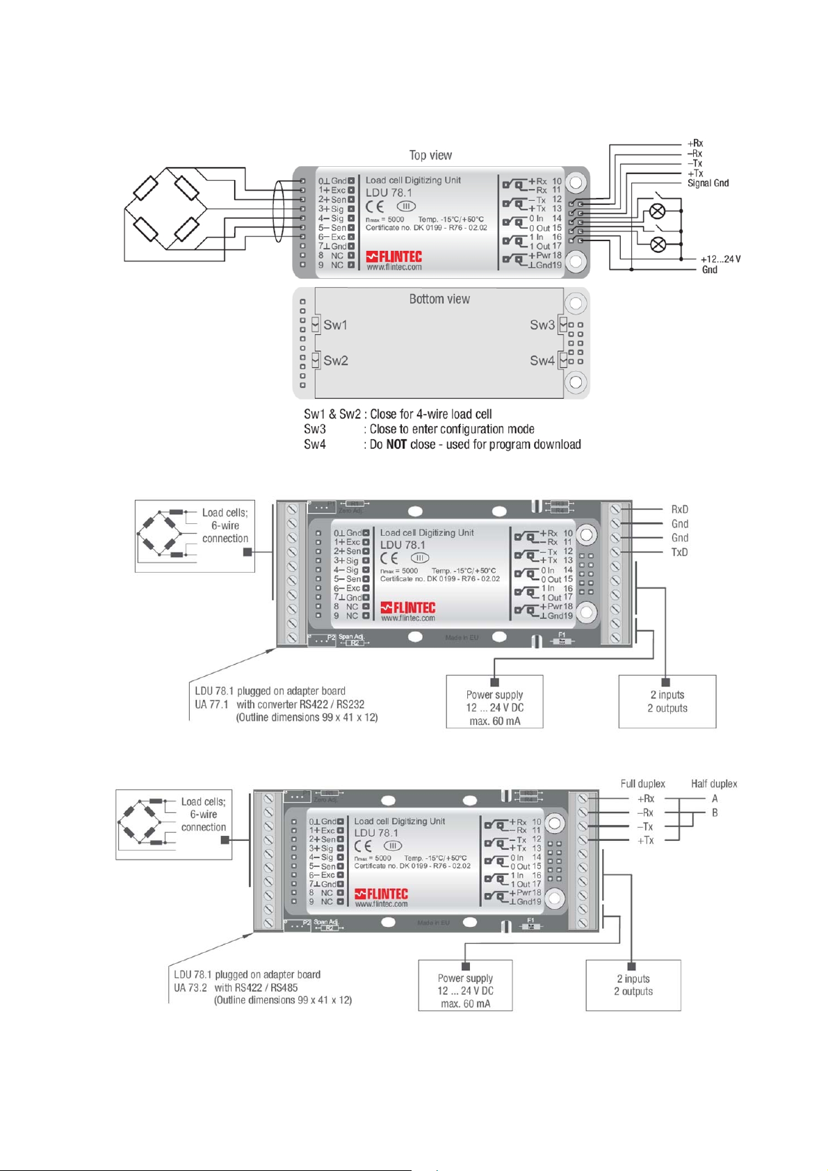
5.1. Wiring
5.2. With Unit Adapter UA 77.1 (RS232)
5.3. With Unit Adapter UA 73.2 (RS422 / RS485 Full-/Half-Duplex)
LDU 78.1 Technical Manual, Rev. 12 May 2011
Page 9 of 36
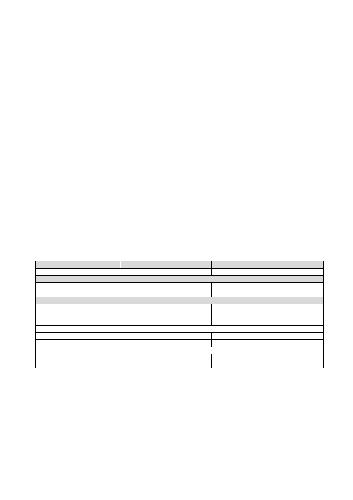
5.4. Terminal Configuration
LDU 78.1
Pin no.
0 Gnd (Shield) Gnd (Shield) Common Ground
1 +Exc + Exc + Excitation for load cell
2 + Sens + Sens + Sense for load cell
3 + Sig + Sig + Signal
4 – Sig – Sig – Signal
5 – Sen – Sen – Sense for load cell
6 – Exc – Exc – Excitation for load cell
7 Gnd Gnd Signal ground / 0 V DC
8 NC NC Not connected
9 NC NC Not connected
10 + Rx RxD (RS232) Receive
11 - Rx Gnd (RS232) UA 73.2: Receive / UA 77.1: Common ground RS232
12 - Tx Gnd (RS232) UA 77.1: Senden / UA 77.1: Common ground RS232
13 + Tx TxD (RS232) Transmit
14 0 In 0 In Digital input 0 (with reference to ground)
15 0 out 0 out Digital output 0 (with reference to ground)
16 1 In 1 In Digital input 1 (with reference to ground)
17 1 Out 1 Out Digital output 1 (with reference to ground)
18 + PWR + PWR Power supply 12...24 V DC
19 Gnd Gnd Common ground / 0 V DC
Remarks:
UA 73.2 (see chapter 5.3) is prepared for full-duplex operation
Valid for half-duplex operation: pin no. 10 + 13 = A and pin no. 11 + 12 = B
UA 77.1 with integrated RS422/RS232 converter (see chapter 5.2)
UA 73.2 UA 77.1 Function
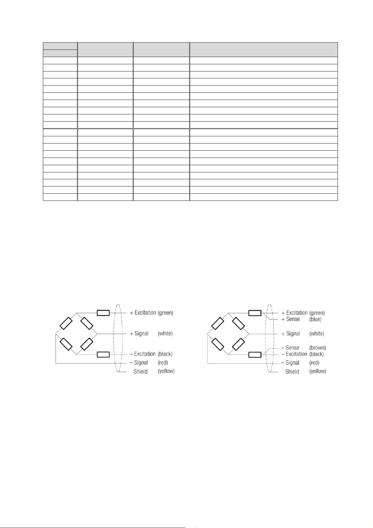
5.5. Load Cell Connection
The load cell wiring should be made carefully before energizing to avoid damages to the amplifier and the load
cells. The input resistance of the load cells that you want to connect should be more than 250 Ω.
The sense pins of the instrument should be connected. In 4-wire installations the switches SW1 and SW2 (see
chapter 5.1) have to be short circuited.
Flintec load cell; 4 wire connection Flintec load cell; 6 wire connection
LDU 78.1 Technical Manual, Rev. 12 May 2011
Page 10 of 36
6. Calibration and Calibration Sequence
The calibration of LDU 78.1 is only possible after starting a calibration sequence (compare with chapter 8.2).
Command CE: Calibration enable – returns the current TAC value
Command CM1 / CM2 /CM3: Calibrate maximum display – sets the max. allowable display value
Command CI: Calibrate minimum – sets the minimum allowable display value
Command MR: Multi-range / Multi-interval
Command DS: Display step size – sets the output incremental step size
Command DP: Decimal point – sets the position of the output decimal point
Command CZ: Calibrate zero – sets the system zero point
Command CG: Calibrate gain – sets the system gain
Command ZT: Zero track enable / disable
Command IZ: If applicable: Correction of System Zero
Command ZR: If applicable: Zero Range – sets the zero range manually
Command ZI: If applicable: Initial Zero Range
Command WT: If applicable: Warm-up time
Command FD : If applicable: Reset to factory default settings
Command CS : Save calibration data (TAC counter automatically incremented by 1)
Preparing the calibration:
Check, if the max value of the display is set sufficiently high (see chapter 8.2: command CM n)
Check, if the no motion conditions are defined reasonable (chapter 8.3: e.g. NR = 1, NT = 1000)
Set the IIR filter frequency to 0.5 Hz (see chapter 8.4: FM = 0, FL = 7)
Example: Setup of zero point, system gain and decimal point
The chosen calibration weight has the value 5000 (increments). That could be 500 g, 5 kg or 5000 kg. We
calibrate with 500 g. The decimal point is set up by command DPx (x = 1, 2 or 3), here 1 figure after the
decimal point. A measured weight of 500 g is displayed as 500.0.
Master (PC / SPS) sends Slave (LDU XX.X) responds Meaning
CE E+00017 (example)
Adjust zero: The scale has to be empty. No load!
CE 17 OK
CZ OK
Adjust gain: First put the calibration weight on the scale (here 500 g)!
CE 17 OK
CG 5000 OK
CG G+05000
CE 17 OK
DP 1 OK
CE 17 OK
CS OK
Zero point, gain and decimal point position were saved in the EEPROM; the calibration counter (TAC) is
increased automatically by 1.
Request: TAC counter CE17
Calibration sequence active
System zero point saved
Calibration sequence active
Setting span
Request: span 5000 d
Calibration sequence active
Setting: decimal point 0000.0
Calibration sequence active
Save calibration data in EEPROM
LDU 78.1 Technical Manual, Rev. 12 May 2011
Page 11 of 36

7. Commands – Overview
Command Short description Parameter value Page
AD
A n
BR
CE
CG
CI
CL
CM n
CS
CZ
DP
DS
DT
DX
FD
FM
FL
GA
GG
GI
GL
GN
GS
GT
GW
H n
HT
ID
IM
IN
IO
IS
IV
IZ
MR
MT
NR
NT
OF
OP
PI
RS
RT
RW
RZ
SA
SD
SG
Communication: Device Address 0...255 27
Setpoints: Output of Gros (0) or Net (1) for setpoints S0 and S1 0 or 1 26
Communication: Baud Rate 9600…115200 baud 27
Calibration: Open Calibration Sequence; Read TAC Counter 0...65535 15
Calibration: Set Calibration Gain (Span) at Load > Zero 0...99999 d 16
Calibration: Minimum Output Value –99999...0 d 15
Communication: Close Device None 27
Calibration: Set Maximum Output Value (n = 1, 2 or 3) 1...99999 d 15
Save the Calibration Data (CM, CI, DS, DP, etc.) to the EEPROM None
Calibration: Set Calibration Zero Point – Scale Without Load None
Calibration: Set Decimal Point Position 0...5 16
Calibration: Set Display Step Size 1, 2, 5, 10, …, 200 d 16
Trigger function: Calculation Time for Short-time Average 0...65535 ms 31
Communication: Set Half-duplex (0) or Full-duplex (1) 0 or 1 27
Factory default settings: Write Data to the EEPROM (TAC protected) None 17
Digital filter: Filter Mode 0 or 1 19
Digital filter: Filter Cut-off Frequency 0...7 19
Output: Get Triggered Average Value None 22, 29
Output: Get Gross Value None
Saves an image file from the LDU’s EEPROM None 28
Output: Get Data String “Average/Gross/Status“ None 23
Output: Get Net Value None
Output: Get ADC Sample Value None
Output: Get Tare Value None
Output: Get Data String “Net/Gross/Status“ None
Setpoints: Hysteresis for Setpoint S0 (H0) or S1 (H1) -99999...+99999 d 26
Trigger function: Hold time for Violation of Setpoint Limit 0...65535 ms 32
Device information: Identify Device None
Digital output: Enable Output for External Control 0000...0011 25
Digital input: Input Status None 25
Digital output: Output Status 0000...0011 25
Device information: Identify Device Status None
Device information: Identify Firmware Version None
Calibration: Correction of System Zero None 17
Calibration: Define Multi-interval (0) or Multi-range (1) 0 or 1 15
Trigger function: Measuring Time for Averaging 0...500 ms 29
Motion detection: No-motion Range 0...65535 d 18
Motion detection: No-motion Time Period 0...65535 ms 18
Output: Format of Data String Output 0…3 23
Communication: Open Device xxx 0...255 27
Download a saved image file to the LDU’s EEPROM None 28
Device information: Read serial number None 14
Scale function: Reset Tare and Switch to Gross Indication None
Trigger function: Trigger Window for Re-trigger Function 0...65535 d 21, 31
Scale function: Reset Zero Point None
Auto-transmit: Send Triggered Average Value automatically None 27, 30
Trigger function: Start Delay 0...500 ms 29
Auto-transmit: Send Gross Value continuously None
18, 28
16
22
22
22
22
22
14
14
14
21
21
24
LDU 78.1 Technical Manual, Rev. 12 May 2011
Page 12 of 36

Command Short description Parameter value Page
SL
SN
S0/S1
SR
SS
ST
SW
SX
SZ
TD
TE
TI
TL
TM
TR
TS
TT
TW
UR
WP
WT
ZA
ZI
ZR
ZT
Auto-transmit: Send Data String „Average/Gross/Status“ continuously None 24
Auto-transmit: Send Net Value continuously None
Setpoints: Setup of Setpoints S0 and S1 -99999...+99999 d 26
Reset Firmware (Warm Start) None
Save the Setpoint Data (S0, S1, H0, H1, A0 and A1) to the EEPROM None 28
Scale function: Set Tare and Switch to Net Indication None
Auto-transmit: Send Data String „Net/Gross/Status“ continuously None
Auto-transmit: Send ADC Sample Value continuously None
Scale function: System Zero Point None 21
Communication: Transmission delay 0…255 ms 27
Trigger function: Trigger on Rising Edge (1) or Falling Edge (0) 0 or 1 29
Trigger function: Averaging Time for Automatic Taring 0...65535 ms 32
Trigger function: Trigger Level 0...99999 d 30
Calibration: Tare mode 0 or 1 17
Trigger function: Software Trigger None 29
Trigger function: Stop Value for Re-trigger Function 0...65535 d 31
Trigger function: Averaging Time for Re-trigger Function 0...500 ms 31
Trigger function: Window for Automatic Taring 0...65535 d 31
Digital filter: Update Rate 0, 1, 2...7 20
Save the Setup Data (FL, NR, NT, AD, BR, DX) to the EEPROM None 28
Calibration: Warm-up Time Delay 0...65535 s 17
Scale function: Set System Zero Point using TI setting None 21
Calibration: Initial Zero Range 0...99999 d 17
Calibration: Zero Range 0...99999 d 17
Zero Tracking: Disable (0) or Enable (1) 0 or 1 16
24
14
21
24
24
LDU 78.1 Technical Manual, Rev. 12 May 2011
Page 13 of 36

8. Commands Description
For better clarity, all commands are divided into groups as described on the following pages.
8.1. System Diagnosis Commands – ID, IV, IS, SR, RS
Use these commands you get the LDU XX.X type, firmware version or device status. These commands are
sent without parameters.
8.1.1. ID Get Device Identity
Master (PC / SPS) sends Slave (LDU XX.X) responds
The response to this request gives the actual identity of the active device. This is particularly useful when trying
to identify different device types on a bus.
8.1.2. IV Get Firmware Version
Master (PC / SPS) sends Slave (LDU XX.X) responds
The response to this request gives the firmware version of the active device.
8.1.3. IS Get Device Status
Master (PC / SPS) sends Slave (LDU XX.X) responds
The response to this request comprises of two 3-digit decimal values (067 and 000), which can be decoded
according to the table below:
Leftmost 3-digit value Rightmost 3-digit value
1 Signal stable (no motion) 1 (not used)
2 Zeroing action performed 2 (not used)
3 Tare active 3 (not used)
4 (not used) 4 (not used)
8 (not used) 8 (not used)
16 (not used) 16 (not used)
32 (not used) 32 (not used)
64 (Setpoint-) output 0 active 64 (not used)
The example decodes the result S:067000 as follows:
Note: The bits that are not used are set to zero.
128 (Setpoint-) output 1 active 128 (not used)
Signal stable (no motion) [20 = 1, LSB]
Zeroing action performed [2
Tare not active [= 0]
ID D:7813
IV V:0214
IS
1
= 2]
S:067000 (example)
Output 0 active [27 = 64]
Output 1 not active [= 0]
8.1.4. SR Reset LDU XX.X Firmware
Master (PC / SPS) sends Slave (LDU XX.X) responds
SR OK
This command will respond with ‘OK’ and after maximum 400 ms perform a complete reset of the LDU. It has
the same functionality as power off and on again.
8.1.5. RS Read Serial Number
Issuing the RS command will return the current serial number in the format S:12345678.
Master (PC / SPS) sends Slave (LDU XX.X) responds Meaning
RS S:123456789
LDU 78.1 Technical Manual, Rev. 12 May 2011
Request: RS = 12345678
Page 14 of 36

8.2. Calibration Commands – CE, CM n, CI, MR, DS, DP, CZ, CG, ZT, FD,
IZ, ZR, ZI, WT, TM, CS
8.2.1. CE Read TAC* Counter / Open Calibration Sequence
With this command you can read the TAC counter (*TAC = Traceable Access Code) or you can open a
calibration sequence.
Master (PC / SPS) sends Slave (LDU XX.X) responds Meaning
CE E+00017 (example)
CE 17 OK
This command must be issued PRIOR to any attempt to set the calibration parameters CM n, CI, MR, DS, DP,
CZ, CG, ZT, ZR, FD, LC, LN n or CS. In legal for trade applications the TAC counter can be used to check if
critical parameters have been change without re-verification. After each calibration the TAC counter increases
by 1.
8.2.2. CM n Set Maximum Output Value
This command (CM n with n = 1, 2 or 3) is used to set up the maximum output value (respective the switching
point in multi range applications). Permitted values are from 1 to 99 999.
Master (PC / SPS) sends Slave (LDU XX.X) responds Meaning
CM 1 M+030000
CE E+00017 (example)
CE 17 OK
This value will determine the point at which the output will change to “oooooo”, signifying over-range respective
the point at which the output will change the measuring range / interval size.
Application CM 1 = MAX 1 CM 2 = MAX 2 CM 3 = MAX 3
Single range CM 1 = 1...99 999
Dual range or dual interval
( Command MR)
Triple range or triple interval
Teilungen ( Befehl MR)
It is necessary: 1 MAX 1 < MAX 2 < MAX 3 99 999
Note: The range, in which a scale can be set to zero (SZ) or automatic zero tracking (ZT) is active, is +/- 2% of
CM value. Factory default: CM1 = 99 999, CM 2 = 0, CM 3 = 0
CM 1 50000 OK
CM 2 = 0
(means CM 2 not used)
CM 1 = 1...MAX 1 CM 2 = MAX 1...99 999
CM 1 = 1...MAX 1 CM 2 = MAX 1...MAX 2 CM 3 = MAX 2...99 999
Request: TAC counter CE17
Calibration sequence active
Request: CM 1 = 30 000 d
Request: TAC counter CE17
Calibration sequence active
Setup: CM 1 = 50 000 d
CM 3 = 0
(means CM 3 not used)
8.2.3. CI Set Minimum Output Value
This command is used to set up the minimum output value. Permitted values are from – 99 999 to 0.
Master (PC / SPS) sends Slave (LDU XX.X) responds Meaning
CI I–000009
CE E+00017 (example)
CE 17 OK
CI –10000 OK
This value will determine the point at which the output will change to “uuuuuu”, signifying under-range.
Request: CI = –9 d
Request: TAC counter CE17
Calibration sequence active
Setup: CI = –10 000 d
Note: In bipolar applications (e.g. force- or torque measurements) this parameter defines the max. output value
for input signals with negative sign. Factory default: CI = –9
8.2.4. MR Set Multi-range / Multi-interval
This command is only relevant, if CM 2 > 0 or CM 3 > 0. Is this the case,then this command defines, if the
application is multi-range or multi-interval. Permitted values are 0 (Multi-interval) or 1 (Multi-range).
Master (PC / SPS) sends Slave (LDU XX.X) responds Meaning
MR M+00000
CE E+00017 (example)
CE 17 OK
MR 1 OK
Note: Single range applications ignore this parameter.
LDU 78.1 Technical Manual, Rev. 12 May 2011
Request: MR = 0 (Multi-interval)
Request: TAC counter CE17
Calibration sequence active
Setup: MR = 1 (Multi-range)
Page 15 of 36

8.2.5. DS Set Display Step Size
This command allows the output to step up or down by a unit other than 1.
Permitted values are 1, 2, 5, 10, 20, 50, 100 and 200.
Master (PC / SPS) sends Slave (LDU XX.X) responds Meaning
DS S+00002
CE E+00017 (example)
CE 17 OK
DS 50 OK
Request: Step size 2
Request: TAC counter CE17
Calibration sequence active
Setup: Step size 50
Legal for trade applications allow for up to 10 000 intervals. The allowed step size has to be considered.
8.2.6. DP Set Decimal Point Position
This command allows the decimal point to be positioned anywhere between leftmost and rightmost digits of the
5-digit output result. Position 0 means no decimal point. Factory default: DP = 3
Master (PC / SPS) sends Slave (LDU XX.X) responds Meaning
DP P+00002
CE E+00017 (example)
CE 17 OK
DP 0 OK
Request: Position of decimal point 2
Request: TAC counter CE17
Calibration sequence active
Setup: no decimal point
8.2.7. CZ Set Calibration Zero Point
This is the reference point for all weight calculations, and is subject to TAC control.
Factory default: approx. 0 mV/V input signal
Master (PC / SPS) sends Slave (LDU XX.X) responds Meaning
CE E+00017 (example)
CE 17 OK
CZ 0 OK
Request: TAC counter CE17
Calibration sequence active
Zero point saved
8.2.8. CG Set Calibration Gain (Span)
This is the reference point for calibration under load, and is subject to TAC control.
Permitted values are from 1 to 99 999.
Master (PC / SPS) sends Slave (LDU XX.X) responds Meaning
CG G+10000
CE E+00017 (example)
CE 17 OK
CG 15000 OK
Request: Calibration weight = 10 000 d
Request: TAC counter CE17
Calibration sequence active
Setup: Calibration weight = 15 000 d
For calibration an input signal near the display maximum (CM) will give the best system performance. The
minimum calibration load of at least 20% is recommended. Is the calibration weight smaller than 1% of display
maximum (CM), the LDU will respond with an error message (“ERR”).
Factory default: 20 000 = 2.000 mV/V input signal
8.2.9. ZT Enable / Disable Zero Tracking
This command enables or disables the zero tracking. ZT = 0 disables the zero tracking and ZT = 1 enables the
zero tracking. Issuing the command without any parameter returns the current ZT value.
Master (PC / SPS) sends Slave (LDU XX.X) responds Meaning
ZT Z:001
CE E+00017 (example)
CE 17 OK
ZT 0 OK
Zero tracking will be performed only on results less than +/-0.5 d at a rate of 0.4 d/sec, where d = display step
size (see DS command). The zero can only be tracked to +/- 2% of maximum (see CM n command).
Factory default: ZT = 0 [Disable]
Request: ZT status
Request: TAC counter CE17
Calibration sequence active
Setup: ZT = Disable
LDU 78.1 Technical Manual, Rev. 12 May 2011
Page 16 of 36

8.2.10. FD Reset to Factory Default Settings
This command puts the LDU back to a known state. The data will be written to the EEPROM and the TAC will
be incremented by 1.
Note: All calibration and setup information will be lost by issuing this command!
Master (PC / SPS) sends Slave (LDU XX.X) responds Meaning
CE E+00017 (example)
CE 17 OK
FD OK
Request: TAC counter CE17
Calibration sequence active
Factory default setting
8.2.11. IZ Correction of System Zero
This command can correct the system zero after a successful calibration, e.g. to correct the unknown weight of
a mounting accessoiry which was used to hold the calibration weight during the calibration procedure. By a
simple parallel shift of the gain curve the sensitivity of the scale will stay unaffected.
Master (PC / SPS) sends Slave (LDU XX.X) responds Meaning
CE E+00017 (example)
CE 17 OK
IZ OK
Request: TAC counter CE17
Calibration sequence active
System zero corrected
8.2.12. ZR Zero Range
Sets the zero range manually – this is the range in increments within which the weighing scale can be zeroed.
Issuing the ZR command without any parameter will return the current value. Permitted values are between the
lower limit of 0 (= factory default setting) and the upper limit of 99999. A value of zero enables the standard
zero range of +/-2% of max.
Master (PC / SPS) sends Slave (LDU XX.X) responds Meaning
CE E+00017 (example)
CE 17 OK
ZR 100 OK
Request: TAC counter CE17
Calibration sequence active
Setup: Zero range = 100 d
8.2.13. ZI Initial Zero Range
Defines the initial zero range (0…99999 d). If ZI is non-zero the device will perform an automatic Set-Zero
when the weight stabilizes with the No-motion settings and the weight is within the ZI range. Factory default: 0.
Master (PC / SPS) sends Slave (LDU XX.X) responds Meaning
CE E+00017 (example)
CE 17 OK
ZI 100 OK
Request: TAC counter CE17
Calibration sequence active
Setup: Initial Zero range = 100 d
8.2.14. WT Warm-up time
Sets the warm up time – this command defines a time interval between 0 (= factory default setting) and 65535 s
after power on where the output value will be set to “uuuuuuu” to avoid false readings during the initial
stabilisation period.
Master (PC / SPS) sends Slave (LDU XX.X) responds Meaning
CE E+00017 (example)
CE 17 OK
WT 20 OK
Request: TAC counter CE17
Calibration sequence active
Setup: Warm-up time = 20 s
8.2.15. TM Tare mode
This commands sets the tare mode to R76 compatible (TM = 1: tare values < 0 not allowed; default setting) or
user-defined (TM = 0; any tare value is allowed).
Master (PC / SPS) sends Slave (LDU XX.X) responds Meaning
CE E+00017 (example)
CE 17 OK
TM 1 OK
Request: TAC counter CE17
Calibration sequence active
Setup: Tare mode = 1
LDU 78.1 Technical Manual, Rev. 12 May 2011
Page 17 of 36

8.2.16. CS Save the Calibration Data
This command results in the calibration data being saved to the EEPROM and causes the TAC to be
incremented by 1.
Master (PC / SPS) sends Slave (LDU XX.X) responds Meaning
CE E+00017 (example)
CE 17 OK
CS OK
Request: TAC counter CE17
Calibration sequence active
Calibration values saved
The CS command saves all of the calibration group values, as set by CZ, CG, CM n, DS, DP and ZT. The
command returns ERR and has no updating action unless it is preceded by the CE_XXXXX.
8.3. Motion Detection Commands – NR, NT
The motion detection facility provides a means of disabling certain functions whenever a condition of instability,
or “motion”, is detected. The “no-motion”, or “stable” condition is achieved whenever the signal is steady for the
period of time set by NT, during which it cannot fluctuate by more than NR increments.The stable condition
activates the relevant bit of responses to “Info Status” (IS).
Following functions are disabled if motion is detected: “Calibrate Zero” (CZ) “Calibrate Gain” (CG) “Set Zero”
(SZ) and “Set Tare” (ST). After such a command the system returns an error (“ERR“), if the signal is not stable.
8.3.1. NR Set No-motion Range
This is the range within which the weighing signal is allowed to fluctuate and still be considered as “stable”.
Permitted values are from 1 to 65535.
Master (PC / SPS) sends Slave (LDU XX.X) responds Meaning
NR R+00010
NR 2 OK
WP OK
Example: For NR = 2 the fluctuations within a maximum of ± 2 d, in the period NT, will be considered “stable”.
Factory default: NR = 1 [= ±1d]
Request: NR = 10 d
Setup: NR = 2 d
Setup saved
8.3.2. NT Set No-motion Time Period
This is the time period (in milliseconds) over which the weight signal is checked to see if it is “stable” or has “nomotion“. The weight signal has to vary by less than NR divisions over the time period NT to be considered
‘stable’. Permitted values are from 1 to 65 535.
Master (PC / SPS) sends Slave (LDU XX.X) responds Meaning
NT T+01000
NT 500 OK
WP OK
If the value of NT =500 milliseconds, the output must not fluctuate more than NR increments within 500
milliseconds in order to be considered “stable”.
Factory default: NT = 1 000 [ms]
Request: NT = 1 000 ms
Setup: NT = 500 ms
Setup saved
LDU 78.1 Technical Manual, Rev. 12 May 2011
Page 18 of 36

8.4. Filter Setting Commands – FM, FL, UR
A digital filter can be set which will eliminate most of the unwanted disturbances. The commands FM and FL
are used to define the digital filter settings, the command UR is used to define an averaging of up to 128
measurement values. Please note that these filters are positioned immediately after the A/D Converter and
therefore affect all aspects of the weighing operation.
8.4.1. FM Filter Mode
This command defines the filter mode. Allowed settings are 0 (IIR filter) and 1 (FIR filter).
Master (PC / SPS) sends Slave (LDU XX.X) responds Meaning
FM F+00001
FM 0 OK
WP OK
The digital IIR filter operates as 2nd order low pass filter and Gaussian characteristics. The attenuation is
40dB/decade (12 dB/octave).; compare to mode 0 of the below table
The digital FIR filter operates as lowpass filter; attenuation see mode 1 in the below table.
Default setting: 0 (IIR filter)
8.4.2. FL Filter Settings
This command defines the filter cut-off frequency.
Master (PC / SPS) sends Slave (LDU XX.X) responds Meaning
FL F+00003
FL 1 OK
WP OK
The permitted settings are from 0 and 8 (see below table). The setting 0 disables the filter.
Default setting: 3.
Settings for IIR Filter (Mode 0)
Request: FM = 1 (FIR filter)
Setup: FM = 0 (IIR filter)
Setup saved
Request: FL = 3
Setup: FL = 1
Setup saved
FL Settling time for 0,1%
accuracy (ms)
0
unfiltered
3 dB – corner
frequency (Hz)
** 600
Attenuation at 300 Hz
(dB)
Max. output rate*
(values/s)
1 55 18 57 600
2 122 8 78 600
3 242 4 96 600
4 322 3 104 600
5 482 2 114 600
6 963 1 132 600
7 1923 0,5 149 600
8 3847 0,25 164 600
* Output rate = 600/2UR values/s
** Anti-aliasing filter 17 Hz @60 dB/decade (18 dB/octave)
Settings for FIR Filter (Mode 1)
FL Settling time for
0,1% accuracy
(ms)
0
unfiltered
1 47 19,7 48 64 > 90 > 80 600
2 93 9,8 24 32 > 90 > 40 300
3 140 6,5 16 21 > 90 > 26 200
4 187 4,9 12 16 > 90 > 20 150
5 233 3,9 10 13 > 90 > 16 120
6 280 3,2 8 11 > 90 > 13 100
7 327 2,8 7 9 > 90 > 11 85,7
8 373 2,5 6 8 > 90 > 10 75
** Anti-aliasing filter 17 Hz @60 dB/decade (18 dB/octave)
Note: In mode 1 the output rate will automatically adapte to the selected filter setting.
3 dB –
corner freq.
(Hz)
20 dB
Attenuation
(Hz)
40 dB
Attenuation
(Hz)
Attenuation
in stopband
(dB)
Stop-
band
(Hz)
Max. output
rate*
(values/s)
** 600
LDU 78.1 Technical Manual, Rev. 12 May 2011
Page 19 of 36

8.4.3. UR Update Rate and Averaging
Depending on the selected filter mode this command defines an averaging for the output value. The permitted
settings are from 0 to 7 (see table below). The average value will always be calculated from 2
values.
LDU 78.1 allows for following settings:
UR 0 1 2 3 4 5 6 7
Measurement values / second 1 2 4 8 16 32 64 128
Check / Setup of the averaging:
Master (PC / SPS) sends Slave (LDU XX.X) responds Meaning
UR U+0001
UR 4 OK
WP OK
Default setting: 0 (no averaging, output rate = 600 values / second)
Request: Averaging of 2 values
Setup: Averaging of 16 values
Setup saved
Update rate in Mode 1:
Output rate (values/s)
UR
0 600 600 300 200 150 120 100 85.7 75
1 300 300 150 100 75 60 50 42.85 37.5
2 150 150 75 50 37.5 30 25 21.42 18.75
3 75 75 37,5 25 18.75 15 12.5 10.71 9.38
4 37.5 37,5 18.75 12.5 9.38 7.5 6.25 5.36 4.69
5 18.75 18.75 9.38 6.25 4.69 3.75 3.13 2.68 2.34
6 9.38 9.38 4.69 3.13 2.34 1.88 1.56 1.34 1.17
7 4.69 4.69 2.34 1.56 1.17 0.94 0.78 0.67 0.59
FL0 FL1
19.7 Hz
FL2
9.8 Hz
FL3
6.5 Hz
FL4
4.9 Hz
FL5
3.9 Hz
FL6
3.2 Hz
UR
measurement
FL7
2.8 Hz
FL8
2.5 Hz
LDU 78.1 Technical Manual, Rev. 12 May 2011
Page 20 of 36

8.5. Taring and Zeroing Commands – SZ, ZA, RZ, ST, RT
The following commands allow you to set and reset the zero and tare values. The zero set up during calibration
remains the ‘true zero’ but the new ‘current zero’ can be set up by using the SZ command. If the SZ command
is issued and accepted then all weight values will then be based on the new ‘current zero’. Please remember
that the zero value will be subject to the Zero tracking function if enabled. If the weight signal is not stable (as
defined by the No motion range NR and the No motion time NT) then both the set zero SZ and set tare ST
commands will be disabled. Also the Set Zero SZ command is not allowed if the new zero value required and
the ‘calibration zero’ differ by more than 2 % of the CM value (maximum allowable value).
See chapter 9 Used in “Approved” applications.
8.5.1. SZ Set System Zero
This command sets a new “current zero” which is then the basis of all weight values until further updated by the
zero tracking function, another SZ command or the “reset zero” command RZ.
Master (PC / SPS) sends Slave (LDU XX.X) responds Meaning
SZ OK
The SZ command will fail (LDU responds with ERR) if the new “current zero” is more than 2% (of the CM value)
higher or lower than the “true zero” set during calibration. The SZ command will also fail if the weight signal is
not stable as defined by the No motion range (NR) and the No motion time (NT). If the weight signal is “stable”,
the response to the IS command (Device Status) will show the “signal stable” bit active and the SZ command
will be accepted (OK). If the “signal stable” bit is not active, the SZ command will be rejected and the LDU will
respond with ERR (error).
8.5.2. ZA Set Averaged System Zero
This command will set the system zero as SZ, but using an average over the TI time period (for command TI
see Re-Trigger commands in chapter 8.13).
Set zero performed
8.5.3. RZ Reset Zero
This command cancels the SZ command and the zero reading reverts to that set by the CZ command during
calibration.
Master (PC / SPS) sends Slave (LDU XX.X) responds Meaning
RZ OK
Zero point CZ active
The LDU responds to the RZ command with either OK or ERR. If OK is returned then the “zero action
performed” bit in the Device Status (IS) response will be set to “0”.
8.5.4. ST Set Tare
This command will activate the net weighing function by storing the current weight value as a tare.
The weight signal must be “stable” within the limits set by NR (No Motion Range) and NT (No Motion Time)
commands for the “signal stable” bit to be active and set tare command to be accepted.
Master (PC / SPS) sends Slave (LDU XX.X) responds Meaning
ST OK
Tare performed / Net operation
If the weight signal is “stable”, the response to the IS command (Device Status) will show the “signal stable” bit
active and the ST command will be accepted (OK). If the “signal stable” bit is not active, the ST command will
be rejected and the LDU will respond with ERR (error).
8.5.5. RT Reset Tare
This command resets the tare and the weighing signal returns to gross mode.
Master (PC / SPS) sends Slave (LDU XX.X) responds Meaning
RT OK
The LDU responds to the RT command with either OK or ERR. If OK is returned then the “tare active” bit in the
Device Status (IS) response will be set to “0”.
Tare de-activated / Gross operation
LDU 78.1 Technical Manual, Rev. 12 May 2011
Page 21 of 36

8.6. Output Commands – GG, GN, GT, GS, GW, GA, GL, OF
The following commands “Get” the gross, net, tare and ADC sample values from the LDU 78.1.
8.6.1. GG Get Gross Value
Master (PC / SPS) sends Slave (LDU XX.X) responds Meaning
8.6.2. GN Get Net Value
GG G+01.100
Master (PC / SPS) sends Slave (LDU XX.X) responds Meaning
GN N+01.000
8.6.3. GT Get Tare Value
Master (PC / SPS) sends Slave (LDU XX.X) responds Meaning
GT T+00.100
8.6.4. GS Get ADC Sample Value
This command gets the actual Analogue to Digital Converter (ADC) value. This can be useful during
development or when calibrating to see how much of the ADC range is being used.
Master (PC / SPS) sends Slave (LDU XX.X) responds Meaning
For service purposes it may be helpful to note the GS values for the “no-load” or “zero” output and when the
“calibration load” is applied.
GS S+125785
Gross value: 1.100 d
Net value: 1.000 d
Tare value: 0,100 d
ADC sample value = 125785 d
8.6.5. GW Get Data String “Net, Gross and Status“
Master (PC / SPS) sends Slave (LDU XX.X) responds Meaning
Net value: +000100 d (no decimal point)
Gross value: +001100 d (no decimal point)
Status bit 1: 5 (not used)
Status bit 2: 1 (Hex)
GW
W+000100+0011005109
(example)
Check sum: 09 (Hex)
The status bits 1 and 2 are defined as follows:
Status
Value = 1 Value = 2 Value = 4 Value = 8
Status bit 1 Not used Not used Output 0 active Output 1 active
Status bit 2 Signal stable Set zero performed Tare active Not used
The check sum is the reciprocal value of the sum of all ASCII values within the data string without the check
sum itself.
8.6.6. GA Get Triggered Average Value
This command reads the measurement result of a measurement cycle. The measurement value has been
averaged according the defined measuring time. The trigger commands can be found in chapter 8.12 and 8.13.
Master (PC / SPS) sends Slave (LDU XX.X) responds Meaning
GA A+01.100
Note: For preventing errors during the read out of the data the register GA has stored the value 99999 at the
beginning of the measurement cycle. The measurement result can only be read after the defined measuring
time MT has been elapsed and before a new measurement cycle has been started.
Request: GA = 1100 g
LDU 78.1 Technical Manual, Rev. 12 May 2011
Page 22 of 36

8.6.7. GL Get Data String “Average, Gross and Status“
Master (PC / SPS) sends Slave (LDU XX.X) responds Meaning
Average value: +000100 d (no decimal point)
Gross value: +001100 d (no decimal point)
Status bit 1: 5 (not used)
Status bit 2: 1 (Hex)
GL
L+000100+0011005109
(example)
Check sum: 09 (Hex)
For check sum, status bit 1 and status bit 2 see command GW.
8.6.8. OF Output Format for Data String GW and GL
This command puts the range information and/or the decimal point into the “long” data strings of the GW and
GL output response.
Master (PC / SPS) sends Slave (LDU XX.X) responds Meaning
CE E+00017 (example)
CE 17 OK
OF 1 OK
Output Format
Parameter setting Range Information DecimalPoint in GW/GL response
0 (= factory default) No No
1 Yes No
2 No Yes
3 Yes Yes
e.g. when the range information is selected, the data strings will change from G+00000 to Gn+00000,
where 1 ≤ n ≤ 3.
Request: TAC counter CE17
Calibration sequence active
Setup: OF = 1
LDU 78.1 Technical Manual, Rev. 12 May 2011
Page 23 of 36

8.7. Auto–transmit Commands – SG, SN, SX, SW, SA, SL
The following commands allow the gross weight or net weight values to be continuously sent. Continuous
transmission start as soon as the relevant command has been issued and finishes when any other valid
command is accepted by the LDU 78.1. The data output rate will depend on the baud rate being used e.g. with
a baud rate of 9 600, approximately 100 values per second can be transmitted.
Note: All auto-transmit commands will only work if the LDU 78.1 has been set to full duplex [DX=1].
The continuous transmission of either the gross or net values will stop when another valid command is
received.
8.7.1. SG Send Gross Value continuously
Master (PC / SPS) sends Slave (LDU XX.X) responds Meaning
SG G+01.100
8.7.2. SN Send Net Value continuously
Master (PC / SPS) sends Slave (LDU XX.X) responds Meaning
SN N+01.000
8.7.3. SX Send ADC Sample Value continuously
Master (PC / SPS) sends Slave (LDU XX.X) responds Meaning
SXS S+125785
Gross value: 1,100 d
Net value: 1,000 d
ADC sample value = 125785 d
8.7.4. SW Send Data String “Net, Gross and Status“ continuously
Master (PC / SPS) sends Slave (LDU XX.X) responds Meaning
Net value: +000100 d (no decimal point)
SW
The status bits 1 and 2 are defined as follows:
W+000100+0011005109
(example)
Gross value: +001100 d (no decimal point)
Status bit 1: 5 (not used)
Status bit 2: 1 (Hex)
Check sum: 09 (Hex)
Status
Value = 1 Value = 2 Value = 4 Value = 8
Status bit 1 Not used Not used Output 0 active Output 1 active
Status bit 2 Signal stable Set zero performed Tare active Not used
The check sum is the reciprocal value of the sum of all ASCII values within the data string without the check
sum itself.
8.7.5. SA Send Triggered Average Value automatically
Master (PC / SPS) sends Slave (LDU XX.X) responds Meaning
SA A+01.100
This command will start to auto-transmit the measurement value of the current trigger cycle. The trigger setup
commands are described in chapter 8.12 and 8.13.
Measurement value: 1,100 d
8.7.6. SL Send Data String “Average, Gross and Status“ automatically
Master (PC / SPS) sends Slave (LDU XX.X) responds Meaning
Average value: +000100 d (no decimal point)
SL
L+000100+0011005109
(example)
For check sum, status bit 1 and status bit 2 see command SW.
LDU 78.1 Technical Manual, Rev. 12 May 2011
Gross value: +001100 d (no decimal point)
Status bit 1: 5 (not used)
Status bit 2: 1 (Hex)
Check sum: 09 (Hex)
Page 24 of 36

8.8. Commands for External I/O Control – IN, IO, IM
The LDU 78.1 has 2 independent logic inputs and 2 independent logic outputs. These inputs and outputs can
be configured and controlled completely via the LDU. The logic inputs can be read directly by the host
application and the logic outputs can be fully controlled via the setpoint commands.
The following group of commands allows the status of the 2 logic inputs to be read, the status of the 2 logic
outputs to read or modified and to configure the logic outputs for internal or external control.
The use of the setpoint commands (Sn, Hn, An) are explained in the following chapter 8.9.
8.8.1. IN Read the Status of the Input Channels
This command reads the status of the two logic inputs.
Master (PC / SPS) sends Slave (LDU XX.X) responds Meaning
IN IN:0001
IN IN:0010
IN IN:0011
The status response is in the form of a four digit code where 0 = false and 1 = true (inputs are active “high”), the
least significant bit corresponding to Input 0 etc.
8.8.2. IO Read / Set the Status of the Output Channels
This command reads and can modify the status of the two logic outputs (if enabled by the IM command).
Master (PC / SPS) sends Slave (LDU XX.X) responds Meaning
IO IO:0001
IO IO:0010
IO IO:0011
IO 0001 OK
IO 0010 OK
IO 0011 OK
The status response is in the form of a four digit code where 0 = false and 1 = true (outputs are normally open,
open drain MOSFETs), the least significant bit corresponding to Output 0 etc.
The status of the outputs can be changed by issuing the IO command with the appropriate 4 digit code e.g. IO
0001 where in this example output 0 will be activated (FET conducting). Please note that the status of the logic
outputs is normally determined by the internal setpoints (see chapter 8.10) and therefore setting the logic
output status using the IO commands is not allowed.
However, the IM command can be used to allow the status of the logic outputs to be set via the IO command or
set their status directly by the host application. Factory default: IO=0000
Request: Input 0 is active
Request: Input 1 is active
Request: Inputs 0 and 1 are active
Request: Output 0 is active
Request: Output 1 is active
Request: Outputs 0 and 1 are active
Setup: Output 0 is active
Setup: Output 1 is active
Setup: Outputs 0 and 1 are active
8.8.3. IM Control of the logic outputs by the host application
The logic outputs can be controlled by the host application (as opposed to the normal internal setpoints) if they
are enabled by the IM command and the appropriate 4 digit code.
Master (PC / SPS) sends Slave (LDU XX.X) responds Meaning
IM IM:0001
IM IM:0010
IM IM:0011
IM 0001 OK
IM 0010 OK
IM 0011 OK
IM 0000 OK
A “1” bit in the code enables the corresponding logic output to be controlled by the host application using the IO
command. A “0” in the code leaves the corresponding logic output controlled by the internal setpoint. Logic
output 0 is again the least significant bit.
Note: When reading the status of the logic outputs using the IO command, the setpoint status will be returned
regardless of the IM setting. Sending IM 0000 disables the external logic output control.
Factory default: IM=0000
LDU 78.1 Technical Manual, Rev. 12 May 2011
Request: Output 0 enabled
Request: Output 1 enabled
Request: Outputs 0 and 1 enabled
Setup: Output 0 enabled
Einstellung: Output 1 enabled
Einstellung: Outputs 0 and 1 enabled
Einstellung: Both outputs disabled
Page 25 of 36

8.9. Setpoint Output Commands – Sn, Hn, An
The LDU 78.1 has 2 logic outputs where the status depends on the weight value (setpoint). Each logic output
can be assigned an independent setpoint value (Sn) with a corresponding hysteresis/switch action (Hn) and
allocation (An – switch on the gross or the net weight).
8.9.1. S n Setpoint Value
Master (PC / SPS) sends Slave (LDU XX.X) responds Meaning
S0 O+01500
S0 03000 OK
S1 O+01500
S1 03000 OK
8.9.2. H n Setpoint Hysteresis and Switching Action
The wished switching logic will be defined by the numeric value and the polarity of the setpoint hysteresis.
The outputs can operate as “normally closed” (negative polarity) or “normally open” (positive polarity).
Example
Setpoint Hysteresis Weight Output open Output closed
S0 = 2000 kg H0 = -100kg increasing > 2100 kg
S0 = 2000 kg H0 = -100kg decreasing
S0 = 2000 kg H0 = 100kg increasing
S0 = 2000 kg H0 = 100kg decreasing < 1900 kg
Example for negative hysteresis and setpoint S0 = 2000 kg (line 1 + 2 of the table above):
When the weight is increasing between 0 kg and 2100 kg the logic output is “closed”. Once the weight exceeds
2100 kg then the logic output will be “open”. The logic output will get “closed” again when the weight value
drops below 2000 kg.
Example for positive hysteresis and setpoint S0 = 2000 kg (line 3 + 4 of the table above):
When the weight is increasing between 0 kg and 2000 kg the logic output is “open”. Once the weight exceeds
2000 kg then the logic output will be “closed”. The logic output will re-open again when the weight value drops
below 1900 kg.
Master (PC / SPS) sends Slave (LDU XX.X) responds Meaning
H0 O-00100
H0 100 OK
H1 O-00100
H1 100 OK
Allowed hysteresis values are within the range from –99999 to +99999 at a step size of 1.
Request: Setpoint S0 = 1500 d
Setup: Setpoint S0 = 3000 d
Request: Setpoint S1 = 1500 d
Setup: Setpoint S1 = 3000 d
2100 kg
2000 kg
2000 kg
< 2000 kg
> 2000 kg
1900 kg
Request: neg. hysteresis setpoint S0
Setup: pos. hysteresis setpoint S0
Request: neg. hysteresis setpoint S1
Setup: pos. hysteresis setpoint S1
8.9.3. A n Allocation of Gros or Net Value
Allowed allocation Meaning
A0 = 0 Gros value controls setpoint S0
A0 = 1 Net value controls setpoint S0
A1 = 0 Gros value controls setpoint S1
A1 = 1 Net value controls setpoint S1
Master (PC / SPS) sends Slave (LDU XX.X) responds Meaning
A0 O+00000
A0 1 OK
A1 O-00000
A1 1 OK
Note: All changes to the setpoint settings have to be stored in the EEPROM using the SS command. See
chapter 8.11
LDU 78.1 Technical Manual, Rev. 12 May 2011
Request: Gros for setpoint S0
Setup: Net for setpoint S0
Request: Gros for setpoint S1
Setup: Net for setpoint S1
Page 26 of 36

8.10. Communication Setup Commands – AD, BR, DX, TD, OP, CL
8.10.1. AD Device Address
This command can set up the device address in the value range from 0 to 255.
Master (PC / SPS) sends Slave (LDU XX.X) responds Meaning
AD A:000
AD 49 OK
Setting the device address to “0“ will cause the device to be permanently active, listening and responding to
every command on the bus without the need for an OP command.
Note: After editing the address you first have to save the changes (command WP) and then restart the device.
8.10.2. BR Baud Rate
With this command the following baud rates can be setup: 9 600, 19 200, 38 400, 57 600 and 115 200 Baud.
Master (PC / SPS) sends Slave (LDU XX.X) responds Meaning
BR B 9600
BR 115200 OK
In chapter 4.3 an automatic search and adjusting mode for the baud rate is described.
Note: After editing the baud rate you first have to save the changes (command WP) and then restart the
device.
8.10.3. DX Half-duplex or Full-duplex
With this command the serial communication can be set to half-duplex (DX=0) or full-duplex (DX=1).
Master (PC / SPS) sends Slave (LDU XX.X) responds Meaning
DX X:000
Half duplex communication can be used for 2 wire RS485 communication.
Attention: The auto transmit commands SG, SF, SW and SL will only work if full duplex communication
(DX=1) is selected.
DX 1 OK
Request: Address 0 (= factory default)
Setup: Address 49
Request: 9 600 Baud (= factory default)
Setup: 115 200 Baud
Request: DX = 0 (Half-duplex, factory default))
Setup: DX = 1 (Full-duplex)
8.10.4. TD Transmission Delay
This command allows time delays from 0 to 255ms before any response from the LDU. This delay may be
necessary in some two wire applications.
Master (PC / SPS) sends Slave (LDU XX.X) responds Meaning
TD T 0
TD 20 OK
Request: TD = 0 ms (factory default)
Setup: TD = 20 ms
8.10.5. OP Open Device
Master (PC / SPS) sends Slave (LDU XX.X) responds Meaning
OP O:00003
OP 14 OK
Request: Device #3 is open
Open device #14
This command, if sent without parameters, requests the address or device number of the device active on the
bus. If sent with parameters, this enables the device defined by the parameters.
The requested device acknowledges its readiness and responds to all bus commands until a further OP
command arrives with a different device address or a CL command is received.
All LDUs operate with an improved communication protocoll:
Each OP command implies a CL command for all non-addressed devices. This simplifies the addressing and
increases the performance within the bus system.
8.10.6. CL Close Device Address n
Master (PC / SPS) sends Slave (LDU XX.X) responds Meaning
CL 3 OK
CL OK
Close device #3
Close all connected devices
LDU 78.1 Technical Manual, Rev. 12 May 2011
Page 27 of 36

8.11. Save Calibration and Setup Data Commands – CS, WP, SS, GI, PI
The calibration and setup parameters can be divided in 3 groups:
Calibration: CM, DS, DP, CZ, CG, ZT, IZ and FD, saved by command CS
Setup: FL, FM, NR, NT, BR, AD, DX and other, saved by command WP
Setpoints: S0, S1, H0, H1, A0, A1, saved by command SS
Note: Calibration data can only be saved if the TAC code is known and precedes the CS command. See the
CE and CS commands in chapter 8.2.
The setup data and the setpoint data will be stored non-volatile in the EEPROM using the WP respective SS
command.
8.11.1. WP Save the Setup Parameters
With this command the settings of the “Filter” (FL, FM) ,the “No-motion” (NR, NT) and the communication (AD,
BR, DX) will saved in the EEPROM.
Master (PC / SPS) sends Slave (LDU XX.X) responds Meaning
WP OK
WP ERR
8.11.2. SS Save Setp oint Parameters
With this command the setpoints (S0, S1), the setpoint hysteresis (H0, H1) and the setpoint allocation (A0, A1)
will be saved in the EEPROM.
Master (PC / SPS) sends Slave (LDU XX.X) responds Meaning
SS OK
SS ERR
Setup data saved
Error
Setpoint parameters saved
Error
8.11.3. GI Save an Image File from the EEPROM
Saves a HEX-INTEL formatted EEPROM image file from the source LDU’s EEPROM. The image file contains
all stored information except the calibration data. This image file can be downloaded to any LDU with the same
firmware type and revision no. as the source LDU.
8.11.4. PI Download an Image File to the EEPROM
Downloads a HEX-INTEL formatted EEPROM image file to the target LDU’s EEPROM. The image file contains
all stored information except the calibration data.
Attention: The target LDU must have same firmware type and revision no. as the source LDU.
LDU 78.1 Technical Manual, Rev. 12 May 2011
Page 28 of 36

8.12. Trigger Commands – SD, MT, GA, TE, TR, TL, SA
Note: All changes to the trigger commands have to be stored in the EEPROM using the WP command. See
chapter 8.11
8.12.1. SD Start Delay Time
This command defines a time delay between the trigger and the start of the measurement.
Setting range: 0 ms to 500 ms.
Master (PC / SPS) sends Slave (LDU XX.X) responds Meaning
SD S+00100
SD 200 OK
Default setting: SD = 0 ms; time plot of a typical checkweigher cycle see below
8.12.2. MT Measuring Time
This command defines the measuring time for the averaged measurement result.
Setting range: 0 ms to 500 ms.
Master (PC / SPS) sends Slave (LDU XX.X) responds Meaning
MT M+00100
MT 500 OK
Note: The setting MT = 0 disables the trigger function and the averaging.
Default setting: MT = 0 [= trigger function disabled]; time plot of a typical checkweigher cycle see below
Request: SD = 100 ms
Setup: SD = 200 ms
Request: MT = 100 ms
Setup: SD = 200 ms
8.12.3. GA Get Triggered Average Value
This command reads the measurement result of a measurement cycle. The measurement value has been
averaged according the defined measuring time.
Master (PC / SPS) sends Slave (LDU XX.X) responds Meaning
GA A+01.100
Request: GA = 1100 g
Note: For preventing errors during the read out of the data the register GA has stored the value 99999 at the
beginning of the measurement cycle. The measurement result can only be read after the defined measuring
time MT has been elapsed and before a new measurement cycle has been started.
8.12.4. TE Trigger Edge
This command defines the trigger edge. Allowed settings are “0” for falling edge and “1” for rising edge. This
command can only be used in conjunction with a hardware trigger on the digital input channel 0.
Master (PC / SPS) sends Slave (LDU XX.X) responds Meaning
TE E+001
TE 0 OK
Request: TE = 1 (rising edge)
Setup: TE = 0 (falling edge)
Default setting: TE = 0 [= falling edge]; time plot of a typical checkweigher cycle see below
8.12.5. TR Software Trigger
This command starts a measurement cycle. Its execution can be compared to a hardware trigger on the digital
input channel 0.
Master (PC / SPS) sends Slave (LDU XX.X) responds Meaning
TR OK
Trigger event
LDU 78.1 Technical Manual, Rev. 12 May 2011
Page 29 of 36

8.12.6. TL Trigger Level
This command defines a level for a rising edge trigger on the measurement signal. Setting range: 0 to 99999.
Master (PC / SPS) sends Slave (LDU XX.X) responds Meaning
TL T+99999
TL 1000 OK
In the example a new measurement cycle would automatically start, if the signal exceeds 1000 d (e.g. 100,0 g;
trigger commands SD and TL).
Default setting: TL = 99999 [ = trigger level disabled]
Note: All trigger possibilities are always available in parallel. If a software trigger (command TR) or a hardware
trigger (Digital input 0) will be used the trigger level should be set to its maixmum value (TL = 99999). This
setting disables the trigger level.
Request: TL = 99999
Setup: TL = 1000
Figure: Time plot of a typical checkweigher cycle
8.12.7. SA Send Triggered Average Value automatically
Master (PC / SPS) sends Slave (LDU XX.X) responds Meaning
SA A+01.100
This command will start to auto-transmit the measurement value of the current trigger cycle.
LDU 78.1 Technical Manual, Rev. 12 May 2011
Measurement value: 1,100 d
Page 30 of 36

8.13. Re-Trigger Commands – RW, TT, TS, DT, TW, TI, HT
Note: All changes to the re-trigger commands have to be stored in the EEPROM using the WP command. See
chapter 8.11
8.13.1. RW Trigger Window for Re-Trigger Function
This command defines a trigger window in unit d (digits) around the current cycle average value. If the signal
leaves this window even for one sample, then the averaging over the time period TT will be started again.
For using the automatic re-trigger function, it is required to define a short-time averaging period (command DT,
see below) before you can use this function.
Default value: RW = 65535 d.
Master (PC / SPS) sends Slave (LDU XX.X) responds Meaning
RW R+65535
RW 500 OK
8.13.2. TT Averaging Time for Re-trigger Function
This command defines an averaging time for calculating the cycle average value. If this time period has been
elapsed, the measurement cycle will be finished at the latest.
The setting TT = 0 disables the re-trigger function. Default setting: TT = 65535 ms.
Master (PC / SPS) sends Slave (LDU XX.X) responds Meaning
TT T+65535
TT 300 OK
Request: RW = 65535 d
Setup: RW = 500 d
Request: TT = 65535 ms
Setup: TT = 300 ms
8.13.3. TS Stop Value for Re-trigger Function
This command defines a stop criteria in unit d (digits) for the re-trigger function. If the signal falls more than this
value TS below the cyclic average value, then the measurement cycle will be finished.
Default setting: TS = 0 d.
Master (PC / SPS) sends Slave (LDU XX.X) responds Meaning
TS T+00000
TS 480 OK
Request: TS = 0 d
Setup: TS = 480 d
8.13.4. DT Short-time Averaging Period
This command defines a time period to calculate short-time averages. If the short-time average falls outside the
trigger window, then the measurement will be started again.
Master (PC / SPS) sends Slave (LDU XX.X) responds Meaning
DT T+00000
DT 50 OK
Request: DT = 0 ms
Setup: DT = 50 ms
8.13.5. TW Window for Automatic Taring
This command defines an ampliude window for the automatic taring. The setting TW = 100 means, that the
system calculates a new tare value, if the averaged net value of the empty scale falls within 100 digits of the net
zero point. The new tare value will be averaged over the time period TI (see below). If the averaged tare value
falls outside this window, then the tare value will not be updated.
Default setting: TW = 0 [= automatic taring disabled]
Master (PC / SPS) sends Slave (LDU XX.X) responds Meaning
TW T+00000
TW 100 OK
Request: TW = 0 d
Setup: TW = 100 d
LDU 78.1 Technical Manual, Rev. 12 May 2011
Page 31 of 36

8.13.6. TI Averaging Time for Automatic Taring
This command defines the averaging time for the automatic taring. Within this time period the system calculates
an averaged tare value. Default setting: TI = 0 ms.
Master (PC / SPS) sends Slave (LDU XX.X) responds Meaning
TI T+00000
TI 200 OK
Request: TI = 0 ms
Setup: TI = 200 ms
8.13.7. HT Hold time for Violation of Setpoint Limit
This command defines the hold time for any violation of the setpoint limit. The signal has to exceed the setpoint
limit continuously at least for this time period before a switch event will be initiated (see chapter 8.9 for setpoint
setup). Default setting: HT = 0 ms.
Master (PC / SPS) sends Slave (LDU XX.X) responds Meaning
HT T+00000
HT 200 OK
Request: HT = 0 ms
Setup: HT = 200 ms
Figure: Time plot of a measurement cycle with the re-trigger function
LDU 78.1 Technical Manual, Rev. 12 May 2011
Page 32 of 36

9. Use in “Approved” Applications
The term “approved” applies whenever the weighing application is intended to be used for “legal-for-trade”
weighing – that is, money will change hands according to the weight result. Such applications are bound by the
legal metrology regulations of the relevant governments around the World, but most countries will comply with
either the relevant EN’s (Euro Norms) or the relevant OIML (Organisation Internationale de Metrologie Legale)
recommendations.
The LDU 78.1 has been approved as a component for use in weighing systems according to OIML
recommendation R76, the highest performance level approved being Class III, 10 000 intervals(e) in single
range, multi-range and multi-interval applications. The approval Authority was the Danish Electronics, Light &
Acoustics (DELTA), and the approval certificate number was DK0199-R76-10.08 Revision 1, dated 28.10.2010.
This approval will allow the use in approved weighing systems throughout Europe, and in many other countries
of the World. To achieve approval on a particular application, it will be necessary to satisfy the relevant
Governmental Trading Standards Authority that the requirements of the various rules and regulations have
been satisfied. This task is greatly simplified if the key components of the weighing system, namely the load
cells and the weighing indicator or digitizer, are already approved as “components”.
Usually, a discussion with the Weighing Equipment Approvals Officers at the relevant National Weights &
Measures Office will then reveal the extent of any pattern testing that may be necessary to ensure compliance.
Restrictions upon usage when in “Approved” applications
A number of performance restrictions must come into force. These restrictions are the number of display
divisions, which become limited to 10 000 divisions, and the sensitivity per display division, which becomes 0.3
μV per division. Once installed in the application, an “approved” application will require “stamping” by an Officer
of the relevant Governmental Trading Standards Department. This certifies the equipment or system as being
in accordance to the relevant regulations and within calibration limits.
The Traceable Access Code (TAC)
The user software must then provide a guard against improper access of the calibration commands (see the
“Calibration Commands” section). The LDU 68.1 digitizer features the “Traceable Access Code” or TAC method
of controlling the access to the calibration commands group. This means that a code is maintained within the
device, and is incremented whenever any change to any of the calibration commands is saved.
When performing the “stamping” test, the Trading Standards Officer will make a note of the TAC, and advise
the user that any change to this code which occurs prior to the regular re-inspection by the Trading Standards
Office, will result in legal prosecution of the user.
The user software is required as a condition of approval, to make the TAC available to the weight display
indicator or console, on demand.
LDU 78.1 Technical Manual, Rev. 12 May 2011
Page 33 of 36

10. Updates – Firmware Download
For a software update the LDU xx.x amplifier has to be connected with a Windows PC via the serial interface
(4-wire connection; RS485/RS422 respective RS485/RS232 converter). The solder pads SW4 on the bottom
side of the PCB must be closed before switching on. After the download the solder pads must be opened again.
A download is accomplished with help of our program “PROG78”.
Firmware update for LDU xx.x series:
First all necessary files (LduDownload.exe, progXX.a20, lduXX.a20) have to be stored in same directory. The
firmware for LDU 78.1 is stored in file lduXX.a20.
Close the solder pads SW 4 on the under side of PCB.
LDU XX.X is de-energized
Close solder pads SW4 on the bottom side (see chapter 5.1)
Switch on LDU xx.x
Start program “LduDownload”.
Press button “Load” and choose file ”lduXX.a20”.
Press button “Program”.
At message “Reset LDU before proceeding” switch the LDU XX.X off and on again and press the button
“OK”.
Download proceeds. – The end will be indicated with ”Programming OK “.
Switch off LDU XX.X .
Open solder pads SW 4
Now use a terminal program or DOP software for running a factory reset of the LDU XX.X by using the
command FD
Note: The command FD is TAC protected. You must issue the CE command with relevant TAC code prior to
the FD command else the FD command will fail.
FD Reset to Factory Default Settings
This command puts the LDU back to a known state. The data will be written to the EEPROM and the TAC will
be incremented by 1.
Note: All calibration and setup information will be lost by issuing this command!
Master (PC / SPS) sends Slave (LDU XX.X) responds Meaning
CE E+00017 (example)
CE 17 OK
FD 0 OK
Request: TAC counter CE17
Calibration sequence active
Factory default setting
LDU 78.1 Technical Manual, Rev. 12 May 2011
Page 34 of 36

LDU 78.1 Technical Manual, Rev. 12 May 2011
Page 35 of 36

www.flintec.com
LDU 78.1 Technical Manual, Rev. 12 May 2011
Page 36 of 36
 Loading...