

Flintec ATEX User Manual
Instruction and Operation Manual
for ATEX Approved Load Cells
Last revision: 24.10.2014
Revision: 9.5
Page 1 / 12
Date of 1st issue: 03.06.2002
issued
checked
released
Date
30.06.2004
11.11.2010
11.11.2010
Signatures
Greulich
Kämper
Dr. Achenbach
Table of contents
0. Valid for Load Cells 2
1 . Preamble 2
2 . Equipment Function 2
2.1 Details 2
2.2 Connection of the Standard Version 2
2.2.1 Examples of suitable circuits with approved safety barriers : 3
2.3 Connections of the 6-wire Version 3
2.4 Advice for Interconnections 4
2.5 Coding of the Load Cells 4
2.6 Reference notes concerning electrostatics 4
2.7 Special notes to the relative inductance and capacities of cables within intrinsically safe circuits 5
3. Designation 5
3.1 Standard Label 3.2 Categorie - Designation 5
4. Commissioning and Installation 6
5. Usage 6
6. Maintenance 6
7. Repair 6
8. Waste Disposal 6
9. EC-Declaration of Conformity 7
10. EC- Type Examination Certificate 8
Instruction and Operation Manual
for ATEX Approved Load Cells
Last revision: 24.10.2014
Revision: 9.5
Page 2 / 12
Date of 1st issue: 03.06.2002
Temperature class / coding
Ui = 30 V, Pi = 4 W
T6 (gas)
-40°C ≤ Ta ≤ 45°C
T5 (gas)
-40°C ≤ Ta ≤ 60°C
T100°C (dust)
-40°C ≤ Ta ≤ 60°C
0. Valid for Load Cells
BK2, PC1, PC2, PC2H, PC6, PC12, PC22, PC42, PC46, PC60, PCB, SB2, SB4, SB5, SB6, SB8, SB14,
SLB, ZLB, RC1, RC2, RC3, UB1, UB5, UB6, ULB
1 . Preamble
This manual covers only the “Ex” relevant aspects.
2 . Equipment Function
Flintec load cells are designed to be used in various kinds of industrial scales and meet the most stringent
accuracy requirements. Certifications have been obtained from Weights & Measures Authorities worldwide.
These load cells are available with different maximum capacities and include accuracy classifications
according to OIML R 60 and / or NTEP.
They offer stainless steel or aluminium construction sealed by welding or improved potting.
This makes them suitable for use in tough industrial environments – they are designed to withstand shock
and fatigue loading.
The load cells can be used in all hazardous areas. The basic structure is always the same.
All standard equipment is provided with a 4-wire shielded conductor cable; equipment with the coding
extension –6w is provided with a 6-wire shielded conductor cable.
(See Chapter 2.5 Coding of Load Cells)
2.1 Details
The following table shows the relationship between maximum total power Pi and maximum ambient
temperature.
2.2 Connection of the Standard Version
Supply circuit: green (+) and black (-)
Signal circuit: white (+) and red (-)
Shield yellow and / or metallic
The intrinsically safe circuit including the load cells must be built up with approved safety barriers
or switch amplifiers, matching the connected weighing indicator.
Instruction and Operation Manual
for ATEX Approved Load Cells
Last revision: 24.10.2014
Revision: 9.5
Page 3 / 12
Date of 1st issue: 03.06.2002
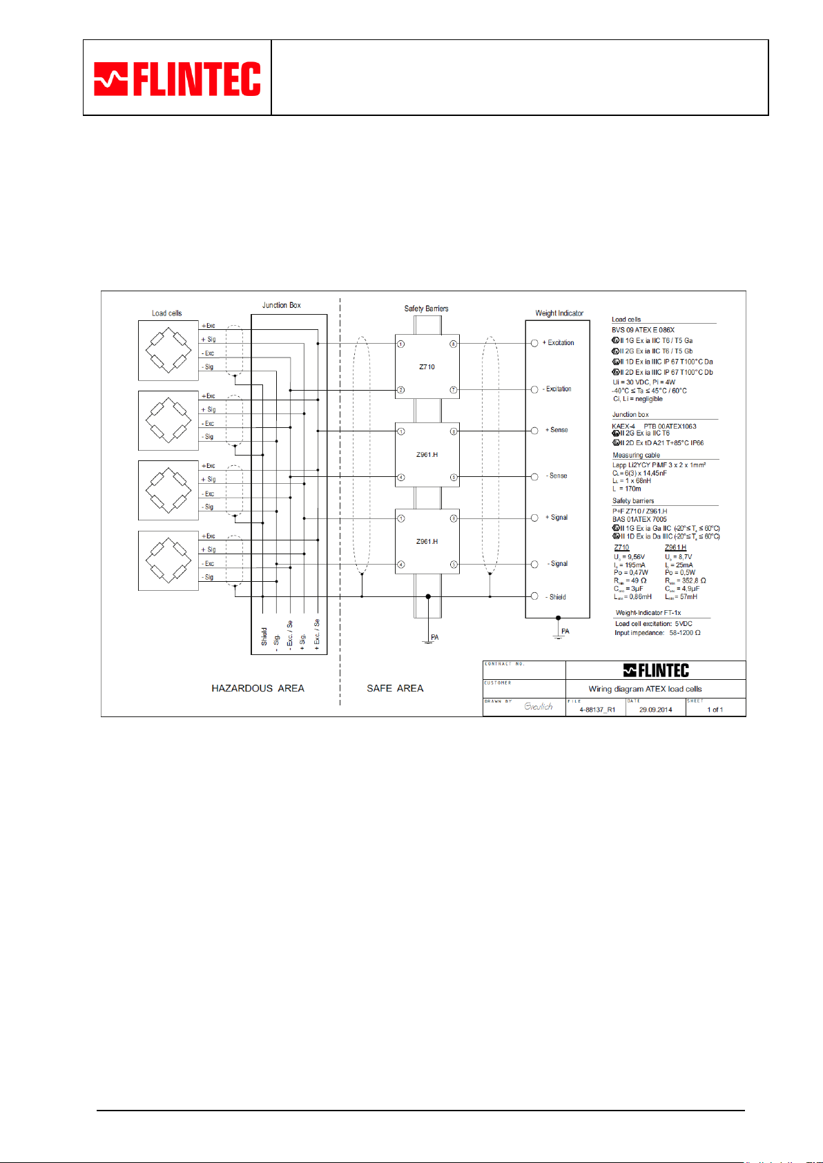
2.2.1 Examples of suitable circuits with approved safety barriers :
Warning: The displayed examples are verified for ignition protection.
The specialist who installs the equipment must take responsibility
for proper operation in combination with various measuring equipment .
Example : With safety barriers for single-ended supply
Wiring diagrams of different circuit examples are available on request
2.3 Connections of the 6-wire Version
The intrinsically safe circuit including the load cells must be built up with approved safety barriers or switch
amplifiers, matching the connected weighing indicator.
Supply circuit: green (+) and black (-)
Signal circuit: white (+) and red (-)
Sense circuit: blue (+) and brown (-)
Shield: yellow and / or metallic

Instruction and Operation Manual
for ATEX Approved Load Cells
Last revision: 24.10.2014
Revision: 9.5
Page 4 / 12
Date of 1st issue: 03.06.2002
Used in:
Max. free projected surface
IIA
IIB
IIC
Zone 0
50 cm²
25 cm²
4 cm²
Zone 1 / 2
100 cm²
100 cm²
20 cm²
Zone 20
No limitation of size,
but exclusion of propagating brush discharges
Zone 21 / 22
2.4 Advice for Interconnections
a) Follow and respect the formation-regulations of the application-country.
E.g. in Germany follow the regulations EN 60079-14 and EN 61241-14.
b) It is ONLY permitted to use approved safety barriers or switch amplifiers for explosive-areas. In
Europe, it is a requirement to have an EC-Type Examination Certificate from a nominated certifying
body for the Zones 0 / 1 / 20 / 21.
c) The rated power, Po ,of all excitation devices must be equal to or less than the power, Pi, of one load cell.
d) The excitation voltage Uo must be equal to or less than the voltage Ui of one load cell.
e) The current, Io ,of all excitation devices must be equal to or less than the current, Ii ,of one load cell.
f) To ensure a potential equalisation with -6w versions, a ground connection between the load cell
housing and the safety barrier’s ground connector is required. In these installations, the shield of the
connection cable is connected to ground potential at both ends.
g) On usual deliveries up to 10 meters, the inductance and capacitance per unit length of the connection
cables is negligible.
2.5 Coding of the Load Cells
The load cells have to be marked according to the following scheme:
AAA-BBB-CCC-DDEF-ZZ, e.g. SB8-100kg-C3-6wsc-12
AAA = Load cell type
BBB = Load cell maximum capacity
CCC = Accuracy class
DD = without marking = 4-wire; 6w = 6-wire
E = without marking = screen of cable not connected to load cell body,
s = screen of cable connected to load cell body
F = without marking = not coated, c = coated
ZZ = Cable length in plain text (in meter) if the load cell cable at delivery is longer than 10m
2.6 Reference notes concerning electrostatics
The load cells can be covered with a non-conductive protective coating as corrosion prevention. In the type
designation code the load cells are marked as "c" in the last position (F).
The free projected surface must not be larger than indicated in the following table after mounting the load
cells (types ***-*** ***-** *c) and propagating brush discharges must be avoided.
If the limiting values of the at maximum tolerable free projected surface cannot be maintained, then
mounting can be done by the user (if propagating brush discharges can be eliminated) and he can point to
this risk on an ESD- warning label (Clean wet only !) on site and in his explosion protection document. In
Zone 2 the installation contractor may permit larger free surfaces on his own responsibility, in accordance
with the EX regulations
 Loading...