

Notes for mounting type SB4, SB5, SB14 and SLB load
cells with type 52-08 rocker pin
Please consider when mounting the load cells:
1. Prepare a flat and horizontal contact surface (support structure), the max. deviation is 0.2°
(3.5 mm/m). The use of a base plate assures a stiff and flat contact surface.
2. The recommended torque for the load cell mounting screws is stated in the data sheet of the
load cell.
3. Prepare a flat and horizontal contact surface for the load carrier, the maximum deviation is
0,5° (8 mm/m).
4. Mount the modules as strainless as possible. Please consider sufficient clearance for the
bumpers (1 mm...3 mm gap).
5. Please pay attention to uniform load distribution.
Mounting
The base plate with screwed on load cells has to be put on the foundation. Mark the locations.
Check the horizontal level with a water level and adjust / underlay something until the tolerances
are kept. The base plate can be bolted or welded to the support structure.
Attention!
Please ground next to the welding point. Under no circumstances it is allowed that
the welding current runs through the load cell. It is recommended to remove the
load cell from the base plate before you start welding.
Load cell installation:
• Grease the thread and the bottom of the screw head of the load cell mounting screws
• Tighten the screws with the specified torque (use a torque wrench).
• Grease the o-Ring and the contact surface of the rocker pin (the recommended standard
grease is Shell Retinax A or BP LSE P2).
• Insert the installation guide pin between the load cell and the loading cup, it centers the
loading cup to the load cell loading hole.
• Insert the loading cup into the load plate and align the load plate.
• Tighten the screws and put on the load carrier.
• Remove the installation guide pin and insert the rocker pin.
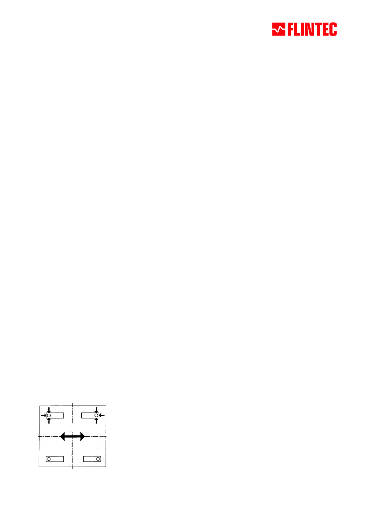
Orientation of the modules:
3 bumpers
Main direction of side forces
February 2008 Page 1 of 1
 Loading...