

Fisher & Paykel OR60 Series Installation Instructions And User Manual

Freestanding cooker
Installation instructions
and User guide
NZ AU
OR60 models


1
Contents
Safety and warnings 2
Installation instructions 6
Using your oven for the rst time 14
Clock and timer 15
Using your oven 16
Cooking functions 17
Automatic cooking 19
Using your gas cooktop 20
Cooktop troubleshooting 24
Care and cleaning 25
Warranty and service 38
Important!
SAVE THESE INSTRUCTIONS
The models shown in this User Guide may not be available in all markets and are
subject to change at any time. For current details about model and speci cation
availability in your country, please go to our website www. sherpaykel.com or
contact your local Fisher & Paykel dealer.
2
Safety and warnings
Important safety precautions
General
To avoid hazard, follow these instructions carefully before installing or using this product.
Please make this information available to the person installing the product as it could
reduce your installation costs.
Installation must comply with your local building and electricity regulations.
Failure to install the cooker correctly could invalidate any warranty or liability claims.
Some appliances have a protective lm. Remove this lm before using the cooker.
Electrical
This cooker is to be installed and connected to the electricity supply only by an authorised
person.
If the installation requires alterations to the domestic electrical system, call a qualified
electrician. The electrician should also check that the electrical system is suitable for the
electricity drawn by the cooker.
The appliance must be connected to the mains, checking that the voltage corresponds to the
value given in the rating plate and that the electrical cable sections can withstand the load
specified on the plate.
WARNING!
Electrical Shock Hazard
Always disconnect the cooker from the mains electricity supply before
carrying out any maintenance operations or repairs.
Failure to do so may result in death or electrical shock.
Installation
WARNING!
Cut Hazard
Take care - panel edges are sharp.
Failure to use caution could result in injury or cuts.

3
Safety and warnings
A suitable disconnection switch must be incorporated in the permanent wiring, mounted
and positioned to comply with the local wiring rules and regulations. The switch must
be of an approved type installed in the fixed wiring and provide a 3 mm air gap contact
separation in all poles in accordance with the local wiring rules.
In Australia and New Zealand, a switch of the approved type with a 3 mm air gap must be
installed in the active (phase) conductor of the fixed wiring.
The switch must always be accessible.
The power supply cable must not touch any hot parts and must be positioned so that it does
not exceed 75 °C at any point.
To connect the cooker to the mains, do not use adapters, reducers or branching devices as
they can cause overheating and burning.
This cooker must be connected to a suitable double pole control unit adjacent to the cooker.
No diversity can be applied to this control unit.
If the electrical supply cord is damaged, it must only be replaced by an authorised person.
This cooker must be connected to electrical supply using V105 insulated cable.
The cooker must be earthed.
Voltage and power consumption
220-240 V~ 50 Hz 3100 W
4
Safety and warnings
Operation
Your freestanding cooker has been carefully designed to operate safely during normal
cooking procedures. Please keep the following guidelines in mind when you are using it:
WARNING!
Explosion Hazard
Do not store ammable materials such as gasoline near the cooktop.
Do not store ammable material in the oven or drawer.
Do not spray aerosols near the cooktop during use.
Failure to do so may result in death or serious injury.
WARNING!
Electrical Shock Hazard
Switch the cooker o at the wall before replacing fuses or the oven lamp.
Failure to do so may result in death or electrical shock.
WARNING!
Hot Surface Hazard
Accessible parts may become hot when this cooker is in use.
To avoid burns and scalds keep children away.
Do not touch hot surfaces inside the oven.
Use oven mitts or other protection when handling hot surfaces such as oven
shelves or dishes.
Take care when opening the oven door.
Let hot air or steam escape before removing or replacing food.
Do not touch the cooktop components, burners, trivets/pan supports or the
base when hot.
Before cleaning, turn the cooker o and make sure it is cool.
Failure to do so could result in burns and scalds.

5
Important safety precautions
Isolating switch: make sure this cooker is connected to a circuit which incorporates an
isolating switch providing full disconnection from the power supply.
Household appliances are not intended to be played with by children.
Children, or persons with a disability which limits their ability to use the appliance, should
have a responsible person to instruct them in its use. The instructor should be satisfied that
they can use the appliance without danger to themselves or their surroundings.
Safe food handling: leave food in the oven for as short a time as possible before and after
cooking. This is to avoid contamination by organisms which may cause food poisoning. Take
particular care during warmer weather.
Do not place aluminium foil, dishes, trays, water or ice on the oven floor during cooking as
this will irreversibly damage the enamel.
Do not line the walls with aluminium foil.
Do not stand on the door, or place heavy objects on it.
Do not use harsh abrasive cleaners or sharp metal scrapers to clean the oven door glass
since they scratch the surface, which may result in shattering of the glass.
Do not use a steam cleaner to clean any part of the cooker.
Do not use an asbestos mat or decorative covers between the flame and the saucepan as
this may cause serious damage to your cooktop.
Do not place aluminium foil or plastic dishes on the cooktop burners.
Do not let large saucepans or frying pans overlap the bench as this can deflect heat onto
your benchtop and damage the surface.
Do not let large saucepans, frying pans or woks push any other pans aside. This could make
them unstable or deflect heat onto your benchtop and damage the surface.
Saucepan handles may be hot to touch. Ensure saucepan handles do not overhang other
gas burners that are on. Keep handles out of reach of children.
If the electrical supply cord is damaged, it must only be replaced by an authorised person.
This cooker is not to be used as a space heater, especially if it is installed in marine craft or
in a caravan.
The use of a gas cooking appliance results in the production of heat and moisture in the
room in which it is installed. Ensure the kitchen is well ventilated. Keep natural ventilation
holes open or install a mechanical ventilation device (mechanical extractor hood).
Prolonged intensive use of the appliance may call for additional ventilation, for example
opening of a window, or more effective ventilation, for example increasing the level of
mechanical ventilation where present.
Safety and warnings
6
Installation instructions
Clearances
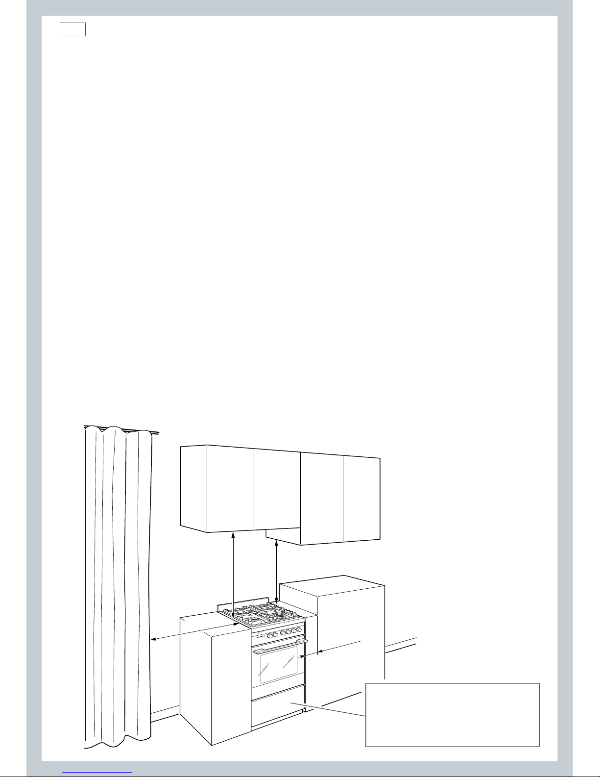
Installation clearances and protection of combustible surfaces shall comply with the current
local regulations eg. AG 601 (AS 5601) Gas Installations code. Installation shall comply with
the dimension in Fig. 1 bearing in mind that:
Overhead Clearances
In no case shall the clearances above the highest part of the cooker be less than 600
mm or, for an overhead exhaust fan, 750 mm. AII other downward facing combustible
surfaces less than 600 mm above the cooker surface shall be protected for the full width
of the cooking surface in accordance with the standards noted above. In no case shall the
clearance be less than 450 mm.
Rear and Side Clearances
Where the distance from the periphery of the nearest burner to any vertical combustible
surface is less than 200 mm, the surface shall be protected in accordance with the
standards to a height of not less than 150 mm above the cooking surface for the full
width or depth of the cooking surface. Where the distance from the periphery of the
nearest burner to any horizontal combustible surface is less than 200 mm, the horizontal
surface shall be more than 10 mm below the surface of the hob, or the horizontal surface
requirement above.
Protection of combustible surfaces
The standards above specify that, where required, protection shall ensure that the surface
temperature of the combustible surface does not exceed 65°C above room temperature. Do
not install the cooker near flammable materials (eg curtains). If you stand the cooker on a
pedestal, make sure you provide safety measures to keep it in place.
Fig. 1 Dimensions and correct
distances from cooker
105 mm
500 mm
450 mm
750 mm
Cooker overall dimensions [mm]
• height: min 900 - max 915
• width: 600
• depth: 600
7
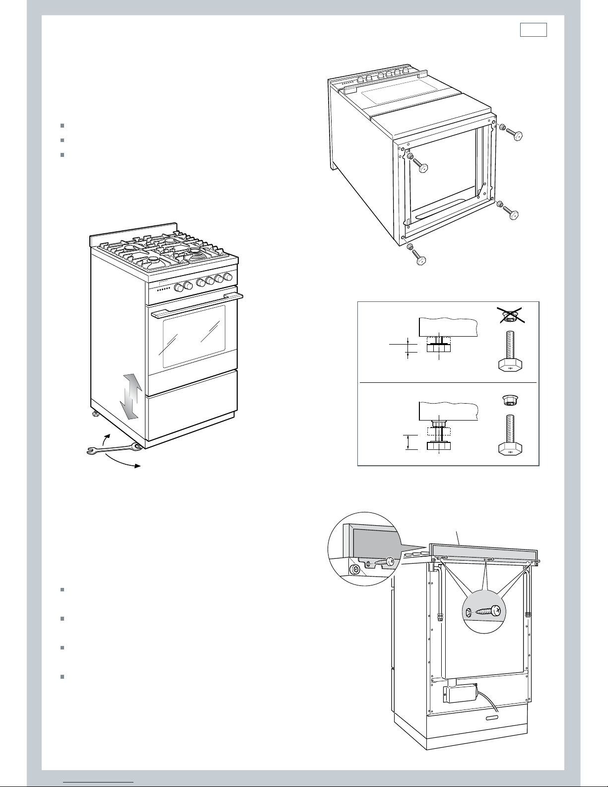
Fig. 2b Fitting the optional spacer
(supplied with the cooker
in a separate kit)
Levelling the cooker
To fit the adjustable feet:
Place the cooker on its back, as shown.
Screw the four feet to the cooker.
Stand the cooker and level it by
screwing or unscrewing the feet with a
spanner.
Installation instructions
Backguard
Before installing the cooker, assemble the
backguard “B” .
The backguard “B” can be found packed at the
rear of the cooker.
Before assembling, remove any protective film/
adhesive tape.
Remove the three screws “A” from the rear of
the cooktop.
Assemble the backguard as shown and fix it by
screwing the three screws “A”.
Fig. 3 Assembling the backguard
AA
B
Fig. 2a Fitting the
adjustable feet
(supplied with the cooker
in a separate kit)
+ 8 mm
+ 15 mm
0
+ 8 mm
Fig. 2c Levelling the cooker
8
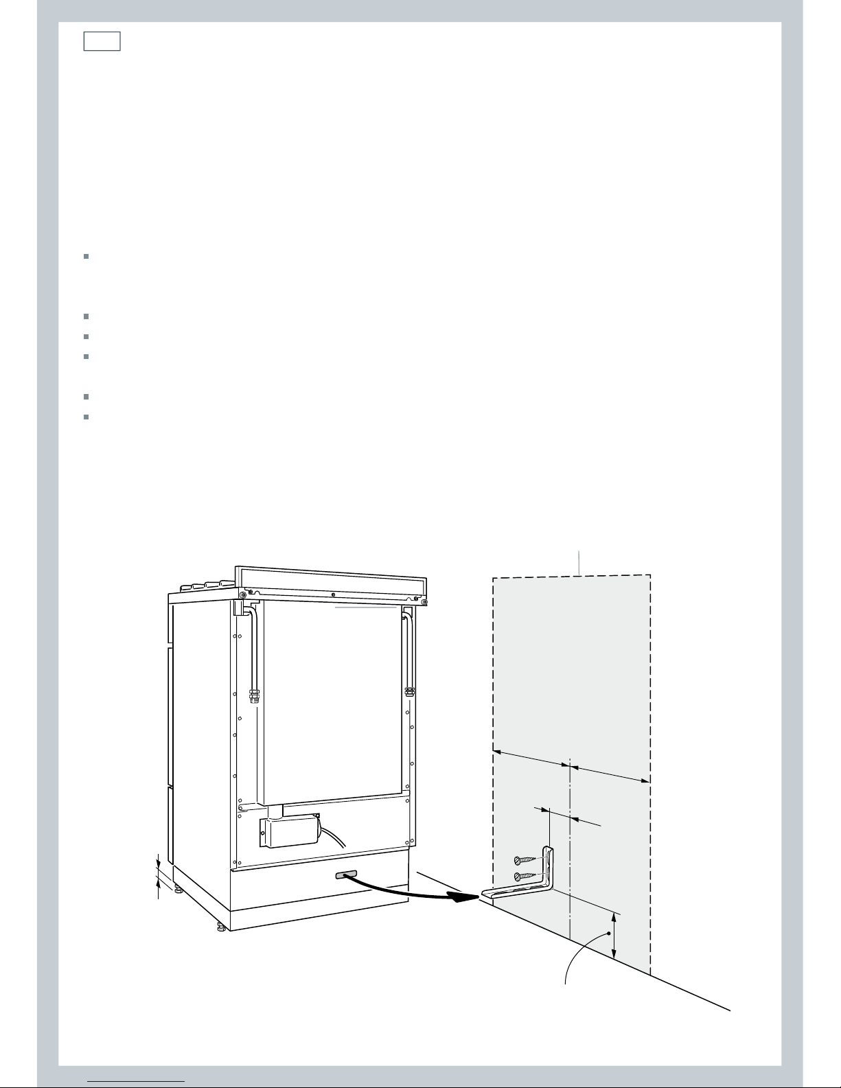
Anti-tilt bracket
To fit the anti-tilt bracket:
After you have located where the cooker is to be positioned, mark on the wall the place
where the two screws of the anti-tilt bracket have to be fitted. Please follow the indications
given in the drawing below.
Make two 8 mm diameter holes in the wall and insert the plastic plugs.
Loosely attach the anti-tilt bracket with two screws.
Move the cooker to the wall and adjust the height of the anti-tilt bracket so that it can
engage in the slot on the cooker’s back.
Tightly attach the anti-tilt bracket.
Push the cooker against the wall so that the anti-tilt bracket is fully inserted into the slot
on the cooker’s back.
Important!
To restrain the appliance and prevent it tipping accidentally, fit a bracket to its rear to fix it
securely to the wall.
Installation instructions
Dotted line showing the position
of the cooker when installed
min 95 - max 110
(depending on feet regulation)
75
=
=
0
+15
Fig. 4 Fitting the anti-tilt bracket
9
Gas supply
The gas connection must be carried out by an authorised person according to the relevant
standards.
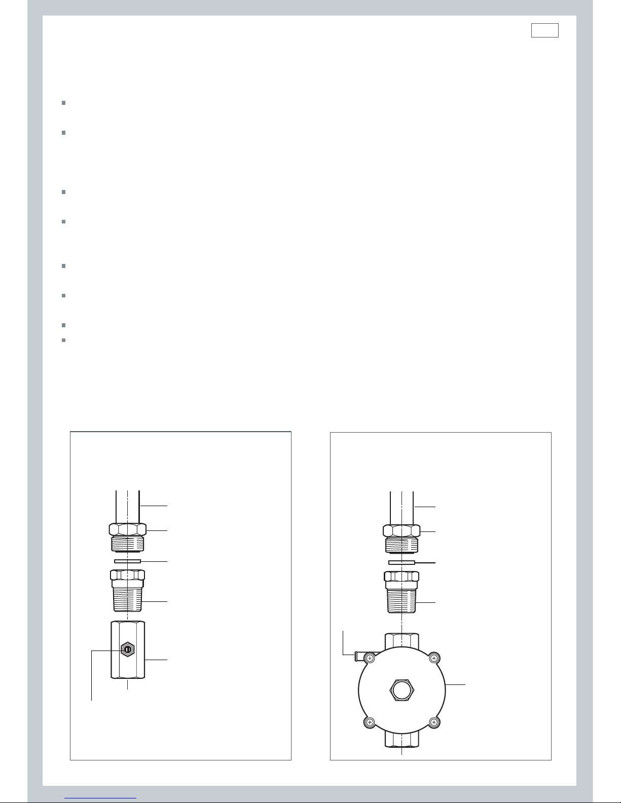
Before connecting the appliance to the gas main, mount the brass conical adaptor onto the
gas inlet pipe, upon which the gasket has been placed (see Fig.s following).
Conical adaptor and gasket are supplied with the appliance (packed with conversion kit for
use with Natural gas or Propane gas).
This appliance is suitable for use with Natural gas or Propane gas. (Check the “gas type”
sticker attached to the appliance).
For Natural gas models, the gas supply is connected to the pressure regulator which is
supplied with the appliance. Adjust the regulator to obtain a test point pressure of 1 kPa
with the two semi-rapid burners operating at the maximum.
For Propane gas models, the gas supply is connected to the test point adaptor which is
supplied with the appliance. Ensure that the supply pressure is regulated to 2.75 kPa.
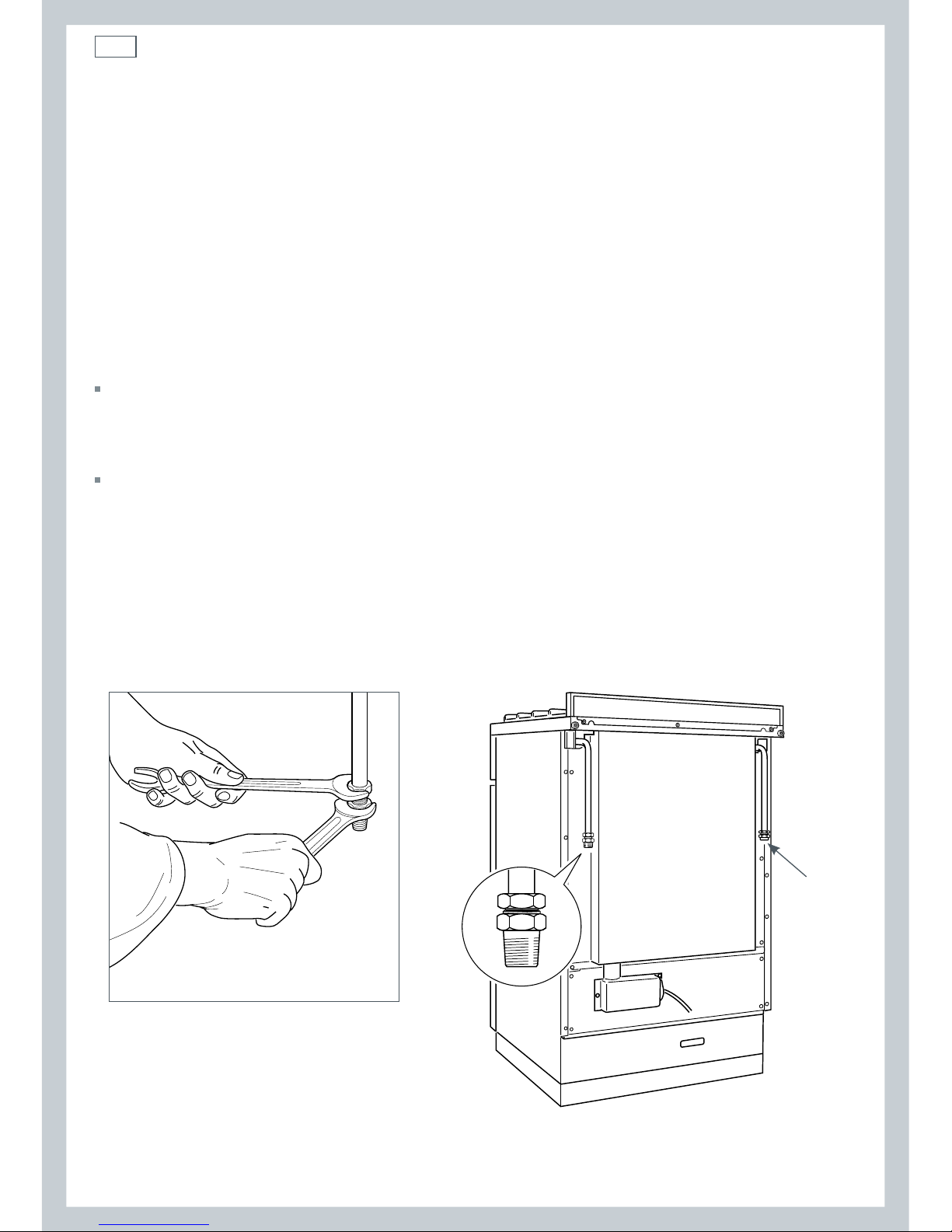
The connection must be made at the rear of appliance (left or right); the pipe is not to
cross the cooker.
Close off the unused inlet with the cap and sealing gasket supplied (Fig. 8).
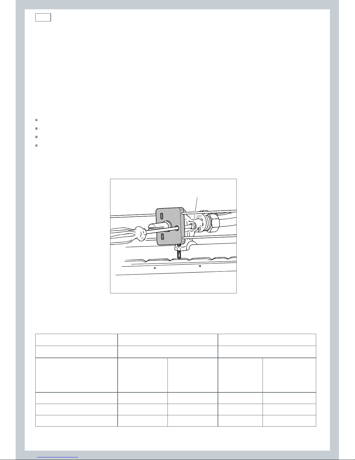
IMPORTANT: Use two spanners to tighten or loosen the connecting pipe, as shown
following.
Installation instructions
Fig. 5 Propane gas connection Fig. 6 Natural gas connection
Gas connection for
PROPANE GAS
Gas connection for
NATURAL GAS
Gas inlet pipe
Nipple
Gasket
Brass conical adaptor
(Thread tight: use
suitable seal)
Gas inlet pipe
Nipple
Gasket
Brass conical adaptor
(Thread tight: use
suitable seal)
Gas regulator
Test point adaptor
Test
point
Test point
10
Installation instructions
After installing the freestanding cooker and connecting the gas supply:
1 Using a suitable leak detection fluid solution (eg Rocol), check each gas connection one at
a time by brushing the solution over the connection.
The presence of bubbles will indicate a leak. If there is a leak, tighten the fitting and then
recheck for leaks.
Important!
Do not use a naked flame to test for leaks.
2 Adjust the test point pressure or supply pressure to the value that is appropriate for the
gas type.
3 Test the operation of the appliance:
Turn on the appliance gas controls and light each burner individually and in combination.
Check for a well-defined blue flame without any yellow tipping. If any abnormality is
evident, then check that the burner cap is located properly and the injector nipple is
aligned correctly.
Check the minimum burner setting by quickly rotating the gas control knob from the
maximum to the minimum position. The flame must not go out. If you need to adjust the
setting, see ‘Adjusting the minimum burner setting’ following.
Important!
This appliance IS NOT SUITABLE for installation with a hose assembly.
Fig. 7 Adjusting the connection pipe
Fig. 8 Gas supply inlets
Plug
11
Installation instructions
Converting to a different gas type
This appliance is suitable for use with Natural gas or Propane gas (check the “gas type”
sticker attached to the appliance). To convert from one gas type to another, you need to
replace the injectors, and then adjust the minimum burning setting.
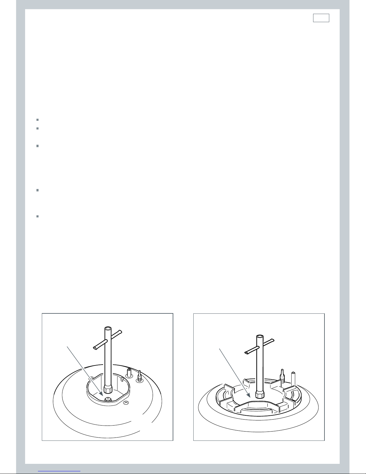
To replace the injectors
Remove pan supports and burners from the cooktop.
Using a spanner, remove the injector (shown in Fig.s following) and replace it with one
according to the gas type (see the ‘Table for the choice of injectors’).
Fix the warning label (supplied with the conversion kit) at the back of the cooker, near the
gas inlet connections. This label states that the gas cooktop has been converted for use
with Propane gas / Natural gas.
Important!
If the cooker is suitable for use with Natural gas and must be converted for use with
Propane gas, before connecting to gas main remove the appliance gas regulator and replace
with test point adaptor.
If the cooker is suitable for use with Propane gas and must be converted for use with
Natural gas, before connecting to the gas main remove the appliance test point adaptor and
replace with gas regulator.
Notes:
- Gas regulator and test point adaptor are supplied with the appliance (packed with the
conversion kit).
- The burners are designed so that regulation of primary air is not required.
Fig. 9 Auxiliary and semi-rapid burners
Fig. 10 Triple ring wok burner
Injector
Injector
12
Regulation screw
Installation instructions
Adjusting the minimum burner setting
Check whether the flame spreads to all burner ports when the burner is lit with the gas
tap set to the minimum position. If some ports do not light, increase the minimum gas rate
setting.
Check whether the burner remains lit even when the gas tap is turned quickly from
the maximum to the minimum position. If the burner does not remain lit, increase the
minimum gas rate setting.
To adjust the minimum gas rate setting:
Turn on the burner.
Turn the tap to the MINIMUM position.
Take off the knob.
Using a small flat screwdriver, turn the screw to the correct regulation.
Note: for Propane gas, the regulation screw is normally tightened up.
Fig.11 Adjusting the minimum burner setting
Table for the choice of injectors
Natural gas Propane gas
Test Point Pressure [kPa]
1.0 2.75
BURNER
Injector
Ori ce Dia.
[mm]
Gas
Consumption
[MJ/h]
Injector
Ori ce Dia.
[mm]
Gas
Consumption
[MJ/h]
Auxiliary 0.85 3.60 0.53 3.60
Semi-rapid 1.12 6.30 0.70 6.30
Triple-ring wok 1.65 13.30 0.95 11.90
 Loading...