


© SANYO Electric Co., Ltd. 2007
• DLP is a registered trademark of Texas Instruments. BrilliantColor and DynamicBlack are trademarks of Texas Instruments.
• IBM is a trademark or registered trademark of International Business Machines Corporation.
• Macintosh, Mac OS X and PowerBook are trademarks of Apple, Inc., registered in the U.S. and other countries.
• Windows, Windows 98, Windows Me, Windows XP or Windows 2000 are trademarks or registered trademarks of Mi-
crosoft Corporation.
• Trademark PJLink is a trademark applied for trademark rights
in Japan, the United States of America and other coun-
tries and areas.
• Other
product and company names mentioned in this user's manual may be the trademarks or registered trademarks of
their respective holders.
Notes
(1) The contents of this user’s manual may not be reprinted in part or whole without permission.
(2) The contents of this user’s manual are subject to change without notice.
(3) The On-Screen Menu and figures in this manual may differ slightly from the product.
(4) Great care has been taken in the preparation of this use
r’s manual; however, should you notice any questionable
points, errors or omissions, please contact us.
(5) Notwithstanding article (3), SANYO will not be responsible for any claims on loss of profit or other matters deemed to
result from using the Projector.
To the Owner
Before installing and operating the projector, read this
manual thoroughly.
The projector provides many convenient features and
functions. Operating the projector properly enables you
to manage those features and maintains it in good condition for many years to come.
Improper operation may result in not only shortening the
product life, but also malfunctions, fire hazard, or other
accidents.
If your projector seems to operate improperly, read this
manual again, check operations and cable connections
and try the solutions in the “Troubleshooting” section in
the back of this booklet. If the problem still persists, contact the dealer where you purchased the projector or the
service center.
CAUTION: TO REDUCE THE RISK OF ELECTRIC
SHOCK, DO NOT REMOVE COVER (OR
BACK). NO USER-SERVICEABLE PARTS
INSIDE EXCEPT LAMP REPLACEMENT.
REFER SERVICING TO QUALIFIED
SERVICE PERSONNEL.
THIS SYMBOL INDICATES THAT
DANGEROUS VOLTAGE CONSTITUTING A
RISK OF ELECTRIC SHOCK IS PRESENT
WITHIN THIS UNIT.
Safety Precaution
WARNING:
TO REDUCE THE RISK OF FIRE OR ELECTRIC
SHOCK, DO NOT EXPOSE THIS APPLIANCE TO
RAIN OR MOISTURE.
− This projector produces intense light from the projection lens. Do not stare directly into the lens as much
as possible, otherwise eye damage could result. Be
especially careful that children do not stare directly
into the beam.
− Install the projector in a proper position. Otherwise it
may result in fire hazard.
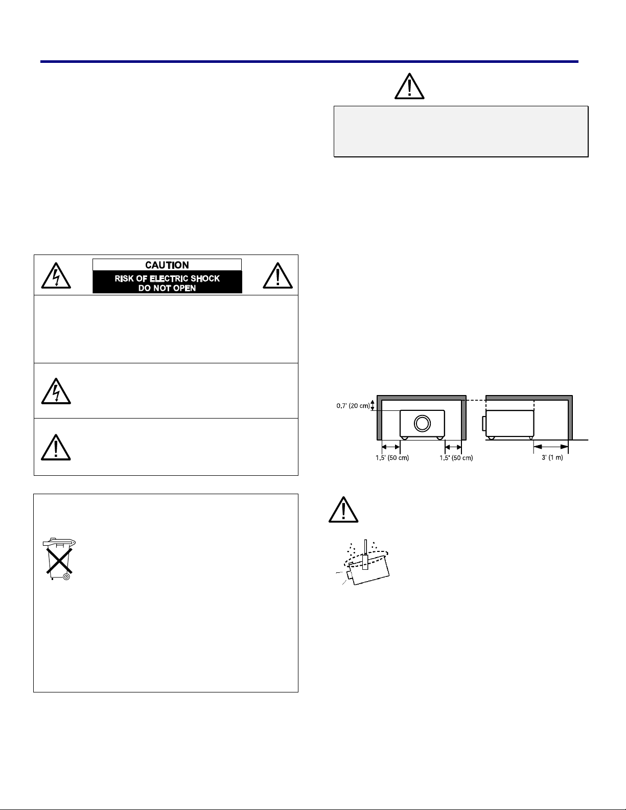
− Allowing the proper amount of space on the top,
sides, and rear of the projector cabinet is critical for
proper air circulation and cooling of the unit. The dimension shown here indicates the minimum space
required.
If the projector is to be built into a compartment or
similarly enclosed, these minimum distances must be
maintained.
− Do not cover the ventilation slot on the projector.
Heat build-up can reduce the service life of your
projector, and can also be dangerous.
SIDE and TOP REAR
THIS SYMBOL INDICATES THAT THERE
ARE IMPORTANT OPERATING AND
MAINTENANCE INSTRUCTIONS IN THE
USER’S MANUAL WITH THIS UNIT.
NOTE: This symbol and recycle system are applied
only to EU countries and not applied to the
countries in the other area of the world.
Your SANYO product is designed and manufactured with high quality materials and
components which can be recycled and
reused.
This symbol means that electrical and electronic equipment, at their end-of-life, should
be disposed of separately from your house-
hold waste.
Please dispose of this equipment at your local community waste collection/recycling center.
In the European Union there are separate collection
systems for used electrical and electronic products.
Please help us to conserve the environment we live in!
READ AND KEEP THIS USER’S MANUAL FOR LATER
USE.
− If the projector is unused for an extended time,
unplug the projector from the power outlet.
CAUTION ON HANGING FROM THE CEILING
When hanging the projector from the ceiling, clean air intake vents, filters, or top of
the projector periodically with a vacuum
cleaner. If you leave the projector unclean
for a long time, the cooling fans can be
clogged with dust, and it may cause a
breakdown.
DO NOT SET THE PROJECTOR IN GREASY, WET, OR
CONDITIONS SUCH AS IN A KITCHEN TO PREVENT
A BREAKDOWN. IF THE PROJECTOR COMES IN
CONTACT WITH OIL OR CHEMICALS, IT MAY
BECOME DETERIORATED.
WARNING:
Not for use in a computer room as defined in the Standard for the Protection of Electronic Computer/Data
Processing Equipment, ANSI/NFPA 75.
Ne peut être utilisé dans une salle d’ordinateurs telle que
définie dans la norme ANSI/NFPA 75 Standard for Protection of Electronic Computer/Data Processing
Equipment.
i
Safety Instructions
All the safety and operating instructions should be read
before the product is operated.
Read all of the instructions given here and retain them for
later use. Unplug this projector from AC power supply
before cleaning. Do not use liquid or aerosol cleaners.
Use a damp cloth for cleaning.
Follow all warnings and instructions marked on the projector.
For added protection to the projector during a lightning
storm, or when it is left unattended and unused for long
periods of time, unplug it from the wall outlet. This will
prevent damage due to lightning and power line surges.
Do not expose this unit to rain or use near water... for
example, in a wet basement, near a swimming pool,
etc...
Do not use attachments not recommended by the manufacturer as they may cause hazards.
Do not place this projector on an unstable cart, stand, or
table. The projector may fall, causing serious injury to a
child or adult, and serious damage to the projector. Use
only with a cart or stand recommended by the manufacturer, or sold with the projector. Wall or shelf mounting
should follow the manufacturer’s instructions, and should
use a mounting kit approved by the manufacturers.
An appliance and cart combination
should be moved with care. Quick
stops, excessive force, and uneven surfaces may cause the appliance and cart
combination to overturn.
Do not install the projector near the ventilation duct of airconditioning equipment.
This projector should be operated only from the type of
power source indicated on the marking label. If you are
not sure of the type of power supplied, consult your authorized dealer or local power company.
Do not overload wall outlets and extension cords as this
can result in fire or electric shock. Do not allow anything to
rest on the power cord. Do not locate this projector where
the cord may be damaged by persons walking on it.
Do not attempt to service this projector yourself as opening or removing covers may expose you to dangerous
voltage or other hazards. Refer all servicing to qualified
service personnel.
Unplug this projector from wall outlet and refer servicing
to qualified service personnel under the following conditions:
a. When the power cord or plug is damaged or frayed.
b. If liquid has been spilled into the projector.
c. If the projector has been exposed to rain or water.
d. If the projector does not operate normally by follow-
ing the operating instructions. Adjust only those
controls that are covered by the operating instructions as improper adjustment of other controls may
result in damage and will often require extensive
work by a qualified technician to restore the projector
to normal operation.
e. If the projector has been dropped or the cabinet has
been damaged.
f. When the projector exhibits a distinct change in per-
formance-this indicates a need for service.
Slots and openings in the back and bottom of the cabinet
are provided for ventilation, to ensure reliable operation
of the equipment and to protect it from overheating.
The openings should never be covered with cloth or
other materials, and the bottom opening should not be
blocked by placing the projector on a bed, sofa, rug, or
other similar surface. This projector should never be
placed near or over a radiator or heat register.
This projector should not be placed in a built-in installation such as a bookcase unless proper ventilation is
provided.
Never push objects of any kind into this projector through
cabinet slots as they may touch dangerous voltage points
or short out parts that could result in a fire or electric
shock. Never spill liquid of any kind on the projector.
When replacement parts are required, be sure the service technician has used replacement parts specified by
the manufacturer that have the same characteristics as
the original part. Unauthorized substitutions may result in
fire, electric shock, or injury to persons.
Upon completion of any service or repairs to this projector, ask the service technician to perform routine safety
checks to determine that the projector is in safe operating
condition.
V
ii
oor de
Bij dit produkt zijn batt e rijen geleverd.
Wanneer dezeleeg zijn, moet u ze
niet weggooien maar inleveren als
KCA.
klant
en in
Neder
land
Important Information
Air Circulation
Openings in the cabinet are provided for ventilation. To
ensure reliable operation of the product and to protect it
from overheating, these openings must not be blocked or
covered.
CAUTION
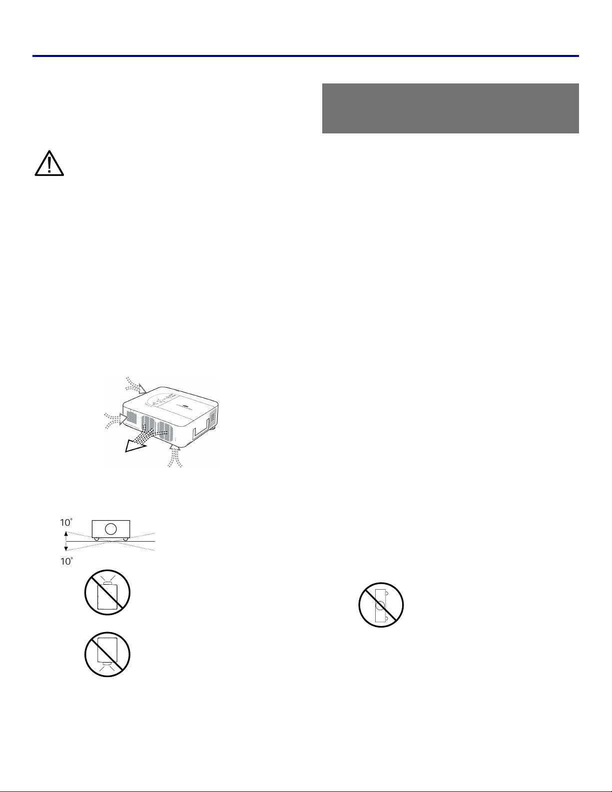
Hot air is from the exhaust vent. When using or installing
the projector, the following precautions should be taken.
− Do not put any flammable objects or spray cans near
the projector, hot air is exhausted from the air vents.
− Keep the exhaust vent at least 3 feet (1 m) away from
any objects.
− Do not touch peripheral parts in the exhaust vents,
especially screws and metallic parts. These areas will
become hot while the projector is used.
− Do not put anything on the cabinet. Objects put on
the cabinet will not only get damaged but may also
cause a fire hazard.
Cooling fans are provided to cool down the projector. The
fans’ running speed is changed according to the temperature inside the projector.
IMPORTANT!
Clean the Filter Regularly!!
The projector uses a lamp which generates significant
heat. The cooling fans and air vents are provided to dissipate the heat by drawing air into the housing and the
filter is located in the intake vents to prevent dust from
getting inside of the projector.
In order to care for the projector appropriately, regular
cleaning is required. Remove any dirt or dust that has
accumulated on the projector and on or in the filter.
When the “Please clean filter” message is displayed, stop
using the projector immediately and clean or replace the
filter.
Blocking the air vents and leaving the projector uncleaned for a long time may not only damage the projector and may require costly repairs but may also cause
accidents or fire.
For maintenance of the filter, refer to “Option” on page 83
and “Replacing the Filters” on pages 97 – 98.
Damages to the projector caused by using an
un-cleaned filter or improper maintenance will void
the warranty on the projector.
Installing the Projector in Proper Position
Install the projector properly. Improper installation may reduce the lamp lifetime and cause a fire hazard.
Do not tilt the projector
more than 10 degrees
above and below.
Do not point the projector
NO UPWARD
up to project an image.
NO SIDEWAYS
Do not point the projector
down to project an image.
NO DOWNWARD
Do not put the projector
on either side to project
an image.
iii
Compliance
F
ederal Communications
This equipment has been tested and found to comply with the limits for a Class B digital device, pursuant to Part 15 of the
FCC Rules. These limits are designed to provide reasonable protection against harmful interference in a residential installation. This equipment generates, uses, and can radiate radio frequency energy and, if not installed and used in
accordance with the instructions, may cause harmful interference to radio communications. However, there is no guarantee
that interference will not occur in a particular installation. If this equipment does cause harmful interference to radio or television reception, which can be determined by turning the equipment off and on, the user is encouraged to try to correct the
interference by one or more of the following measures:
− Reorient or relocate the receiving antenna. Increase the separation between the equipment and receiver.
− Connect the equipment into an outlet on a circuit different from that to which the receiver is connected.
− Consult the dealer or an experienced radio/TV technician for help.
Use of shielded cable is required to comply with class B limits in Subpart B of Part 15 of FCC Rules.
Do not make any changes or modifications to the equipment unless otherwise specified in the instructions. If such changes
or modifications should be made, you could be required to stop operation of the equipment.
Model Number(s) : PDG-DWT50L
Trade Name : Sanyo
Responsible party : SANYO FISHER COMPANY
Address : 21605 Plummer Street, Chatsworth, California 91311 U.S.A.
Telephone No. : (818)998-7322
Commission Notice
AC Power Cord Requirement
The AC Power Cord supplied with this projector meets the requirement for use in the country you purchased it.
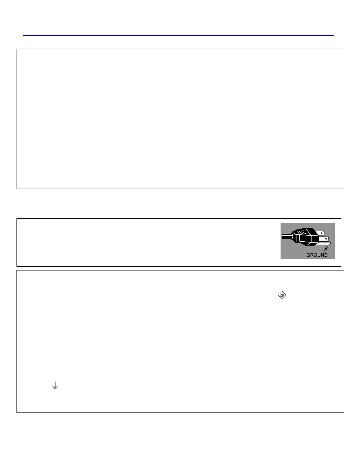
AC Power Cord for the United States and Canada:
AC Power Cord used in the United States and Canada is listed by the Underwriters Laboratories
(UL) and certified by the Canadian Standard Association (CSA).
AC Power Cord has a grounding-type AC line plug. This is a safety feature to be sure that the
plug will fit into the power outlet. Do not try to defeat this safety feature. Should you be unable to
insert the plug into the outlet, contact your electrician.
AC Power Cord for the United Kingdom:
This cord is already fitted with a modulized plug incorporating a fuse, the value of which is indicated on the pin face of the plug. Should
the fuse need to be replaced, an ASTA approved BS 1362 fuse must be used of the same rating, marked thus . If the fuse cover is
detachable, never use the plug with the cover omitted. If a replacement fuse cover is required, ensure it is of the same color as that visible on the pin face of the plug (i.e. red or orange). Fuse covers are available from the Parts Department indicated in your User
Instructions. If the plug supplied is not suitable for your socket outlet, it should be cut off and destroyed. The end of the flexible cord
should be suitably prepared and the correct plug fitted.
WARNING: A PLUG WITH BARED FLEXIBLE CORD IS HAZARDOUS IF ENGAGED IN A LIVE SOCKET OUTLET.
The Wires in this mains lead are colored in accordance with the following code:
Green-and-yellow ············ Earth
Blue ································· Neutral
Brown ······························ Live
As the colors of the wires in the mains lead of this apparatus may not correspond with the colored markings identifying the terminals in
your plug proceed as follows:
The wire which is colored green-and-yellow must be connected to the terminal in the plug which is marked by the letter E or by the safety
earth symbol or colored green or green-and-yellow.
The wire which is colored blue must be connected to the terminal which is marked with the letter N or colored black. The wire which is
colored brown must be connected to the terminal which is marked with the letter L or colored red.
WARNING: THIS APPARATUS MUST BE EARTHED.
THE SOCKET-OUTLET SHOULD BE INSTALLED NEAR THE EQUIPMENT AND EASILY ACCESSIBLE.
iv

Table of Contents
1. INTRODUCTION ..................................................................................................................................................................................1
WHAT’S IN THE BOX?.......................................................................................................................................................................... 1
INTRODUCTION TO THE PROJECTOR...................................................................................................................................................2
Features you’ll enjoy:........................................................................................................................................................................2
PART NAMES OF THE PROJECTOR .....................................................................................................................................................3
Front-right view..................................................................................................................................................................................3
Top view .............................................................................................................................................................................................4
Bottom view .......................................................................................................................................................................................5
TOP FEATURES ...................................................................................................................................................................................6
Lens Controls.....................................................................................................................................................................................6
OSD Controls and Status LEDs......................................................................................................................................................7
TERMINAL PANEL FEATURES .............................................................................................................................................................. 9
PART NAMES OF THE REMOTE CONTROL ........................................................................................................................................11
Battery Installation ..........................................................................................................................................................................13
Operating Range for Wireless Remote Control..........................................................................................................................14
Remote Control Precautions .........................................................................................................................................................14
Remote Control Codes...................................................................................................................................................................14
Using the Remote Control in Wired Operation ...........................................................................................................................15
Carrying the Projector ....................................................................................................................................................................16
2. INSTALLATION AND CONNECTIONS .........................................................................................................................................17
SETTING UP THE SCREEN AND THE PROJECTOR............................................................................................................................. 17
SELECTING A LOCATION....................................................................................................................................................................18
INSTALLING OR REMOVING THE OPTIONAL LENS .............................................................................................................................19
Removing the Existing Lens From the Projector........................................................................................................................19
Installing the New Lens..................................................................................................................................................................20
Installing the New Lens Using the anti-theft screw ....................................................................................................................21
THROW DISTANCE AND SCREEN SIZE .............................................................................................................................................. 22
INSTALLING THE OPTIONAL COLOR WHEEL ..................................................................................................................................... 24
MAKING CONNECTIONS.....................................................................................................................................................................26
Connecting Your PC or Macintosh Computer.............................................................................................................................26
Connecting an External Monitor....................................................................................................................................................28
Connecting Your DVD Player with Component Output.............................................................................................................29
Connecting Your VCR or Laser Disc Player ...............................................................................................................................30
CONNECTING THE SUPPLIED POWER CABLE ...................................................................................................................................31
NOTE ON THE POWER CORD...................................................................................................................................................31
3. PROJECTING AN IMAGE (BASIC OPERATION) ....................................................................................................................... 32
TURNING ON THE PROJECTOR.......................................................................................................................................................... 32
Note on Startup Screen (Menu Language Select screen)........................................................................................................33
SELECTING AN INPUT SOURCE .........................................................................................................................................................34
ADJUSTING THE PICTURE POSITION AND PICTURE SIZE.................................................................................................................. 35
Adjusting Picture Position Manually .............................................................................................................................................35
Lens Shift Adjustable Range.........................................................................................................................................................36
From the Remote Control Unit ......................................................................................................................................................37
Adjusting the Projector Level.........................................................................................................................................................38
OPTIMIZING AN RGB IMAGE AUTOMATICALLY .................................................................................................................................39
Adjusting the Image Using AUTO PC ADJ. ................................................................................................................................39
ADJUSTING VOLUME UP AND DOWN ................................................................................................................................................40
TURNING OFF THE PROJECTOR ........................................................................................................................................................41
About Direct Power Off...................................................................................................................................................................42
After Use...........................................................................................................................................................................................42
4. CONVENIENT FEATURES .............................................................................................................................................................. 43
TURNING OFF THE IMAGE AND SOUND.............................................................................................................................................43
FREEZING A PICTURE........................................................................................................................................................................43
ADJUSTING THE FOCUS/ZOOM MANUALLY....................................................................................................................................... 44
v

Table of Contents
Adjusting by Using the OSD Control Panel.................................................................................................................................44
CHANGING LAMP MODE .................................................................................................................................................................... 45
Changing Lamp Mode by Using the Projector's OSD Control Panel ......................................................................................45
Changing Lamp Mode by Using the Remote Control................................................................................................................46
GETTING INFORMATION..................................................................................................................................................................... 47
ADJUSTING POSITION/TOTAL DOTS/FINE SYNC ..............................................................................................................................48
Adjusting Position/Total Dots/Fine Sync by using the OSD Control Panel ............................................................................48
Correcting Keystone by Using the Remote Control...................................................................................................................49
PREVENTING THE UNAUTHORIZED USE OF THE PROJECTOR .......................................................................................................... 51
Locking the Projector...................................................................................................................................................................... 51
Unlocking the Projector ..................................................................................................................................................................53
USING THE PHYSICAL LOCK.............................................................................................................................................................. 54
Using the Kensington Lock............................................................................................................................................................54
Using the Security Chain Lock......................................................................................................................................................54
5. USING ON-SCREEN DISPLAY....................................................................................................................................................... 55
USING THE MENUS............................................................................................................................................................................55
Navigating the OSD........................................................................................................................................................................55
MENU TREE.......................................................................................................................................................................................57
MENU ELEMENTS ..............................................................................................................................................................................59
SOURCE MENU DESCRIPTIONS AND FUNCTIONS ............................................................................................................................. 60
ADJUST MENU DESCRIPTIONS AND FUNCTIONS ..............................................................................................................................61
Image menu .....................................................................................................................................................................................61
Image options menu .......................................................................................................................................................................62
Video menu......................................................................................................................................................................................64
DETAIL SETTINGS MENU DESCRIPTIONS AND FUNCTIONS .............................................................................................................. 67
Basic .................................................................................................................................................................................................67
White balance..................................................................................................................................................................................69
Color correction ...............................................................................................................................................................................70
SETTING MENU DESCRIPTIONS AND FUNCTIONS............................................................................................................................. 71
Basic .................................................................................................................................................................................................71
Installation ........................................................................................................................................................................................ 75
Network setting................................................................................................................................................................................82
Option ...............................................................................................................................................................................................83
INFORMATION MENU DESCRIPTIONS AND FUNCTIONS..................................................................................................................... 89
Usage time .......................................................................................................................................................................................89
Input ..................................................................................................................................................................................................90
Network.............................................................................................................................................................................................91
Version..............................................................................................................................................................................................92
RESET MENU DESCRIPTIONS AND FUNCTIONS................................................................................................................................93
6. MAINTENANCE .................................................................................................................................................................................94
CLEANING THE PROJECTOR ..............................................................................................................................................................94
Cleaning the Cabinet......................................................................................................................................................................94
Cleaning the Lens ...........................................................................................................................................................................94
Cleaning the Filters.........................................................................................................................................................................95
REPLACING CONSUMABLE PARTS .................................................................................................................................................... 97
Replacing the Filters.......................................................................................................................................................................97
Replacing the Lamps......................................................................................................................................................................99
Resetting the Lamp Time Counter..............................................................................................................................................101
Ordering a Replacement Lamp................................................................................................................................................... 101
7. APPENDIX ........................................................................................................................................................................................102
TROUBLESHOOTING ........................................................................................................................................................................102
Indicator Messages.......................................................................................................................................................................102
Common Problems and Solutions..............................................................................................................................................104
Tips for Troubleshooting ..............................................................................................................................................................104
IMAGE PROBLEMS ........................................................................................................................................................................... 105
vi

Table of Contents
Lamp Problems .............................................................................................................................................................................105
Remote Control Problems ...........................................................................................................................................................106
Audio Problems .............................................................................................................................................................................106
HAVING THE PROJECTOR SERVICED .............................................................................................................................................. 106
8. SPECIFICATIONS ........................................................................................................................................................................... 107
PROJECTOR SPECIFICATIONS......................................................................................................................................................... 107
Optical Specifications ...................................................................................................................................................................107
Electrical Specifications ...............................................................................................................................................................108
Mechanical Specifications ...........................................................................................................................................................109
Environmental Considerations .................................................................................................................................................... 109
Regulations .................................................................................................................................................................................... 109
Optional Parts................................................................................................................................................................................110
CABINET DIMENSIONS..................................................................................................................................................................... 111
PIN ASSIGNMENTS OF MINI D-SUB 15 PIN INPUT CONNECTOR .................................................................................................... 112
COMPATIBLE INPUT SIGNAL LIST.................................................................................................................................................... 113
PC CONTROL CODES AND CABLE CONNECTIONS......................................................................................................................... 115
Functional Execution Command Table......................................................................................................................................115
Status Read Command Table.....................................................................................................................................................116
SCREEN TRIGGER ........................................................................................................................................................................... 117
OPERATION USING HTTP BROWSER.............................................................................................................................................118
Overview.........................................................................................................................................................................................118
Preparation Before Use................................................................................................................................................................118
Handling of the Address for Operation by Using a Browser...................................................................................................118
Configuring Network Settings......................................................................................................................................................119
Structure of the HTTP Server......................................................................................................................................................121
15 PIN GPIO CONTROL .................................................................................................................................................................123
9. TROUBLESHOOTING CHECK LIST ...........................................................................................................................................124
vii
1. Introduction
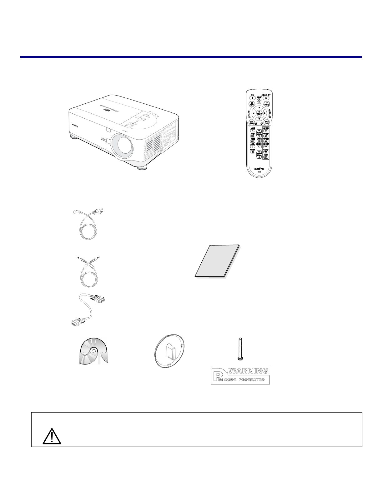
What’s in the Box?
Carefully unpack the projector and check that the following items are included:
PDG-DWT50L Projector Remote Control
(with Two AA alkaline batteries)
Power Cable
(3.6m/11.8 ft.)
→ For North
America,
Europe and
the UK
Remote Cable
(10m/33ft)
VGA Cable
Quick Start Guide
Anti-Theft
CD-ROM
(This User’s manual)
Lens Hole Cap
(Installed)
Screw for lens
x 1
Security
Sticker
Contact your dealer immediately if any items are missing, appear damaged, or if the unit does not work.
CAUTION
Avoid using the projector in dusty environments.
1

1. Introduction
Introduction to the Projector
Features you’ll enjoy:
DLP projector with high resolution
The combination of BrilliantColor™ and a six-segment color wheel (optional) offer a more true color reproduction.
Installation Flexibility
This projector has many useful functions such as powered lens shifting, ceiling and rear projection, variety of extensive optional powered lens with bayonet mount with release button, etc.
Multiple Interface Terminals
The projector has several interface terminals that can support various types of equipment and signals.
Dual Lamp Control System
The two-lamp control system offers high brightness, maintained lamp life and energy savings along with redundancy. The
lamp control function offers brightness of the lamp can be selected. The power management function also reduces power
consumption and maintains lamp life.
Simple Computer System Setting
The projector has the Multi-scan system to conform to almost all computer output signals quickly. Up to UXGA resolution
can be accepted.
Security Function
The Security function helps you to ensure security of the projector. With the Key lock function, you can lock the operation on
the top control. PIN code lock functions prevent unauthorized use of the projector.
Multilanguage Menu Display
Operation menu is available in 8 languages: English, German, French, Italian, Spanish, Swedish, Chinese, and Japanese.
Multi-use Remote Control
Use the remote control as wired or wireless. Eight remote control codes are available.
3W + 3W Stereo Speaker
Built in 3W x 2 speakers are provided.
Helpful Maintenance Functions
The lamp and filter maintenance functions provide for better and proper maintenance of the projector. Easy maintenance
cover is provided for lamp and color wheel replacement.
Direct Power Off and On Start
The Direct Power Off function allows the projector to be turned off (even when projecting an image) using a power strip
equipped with a switch and a breaker. The On Start function allows the projector to be turned on by supplied AC power.
Note:
Before using Direct Power Off, be sure to allow at least 20 minutes immediately after turning on the projector
and starting to display an image. Also, the power cord can be removed immediately after turning off the projector. On Start manual may differ slightly from the product.
On Start eliminates the need to always use the POWER (ON/STANDBY) button on the remote control or
projector cabinet.
2
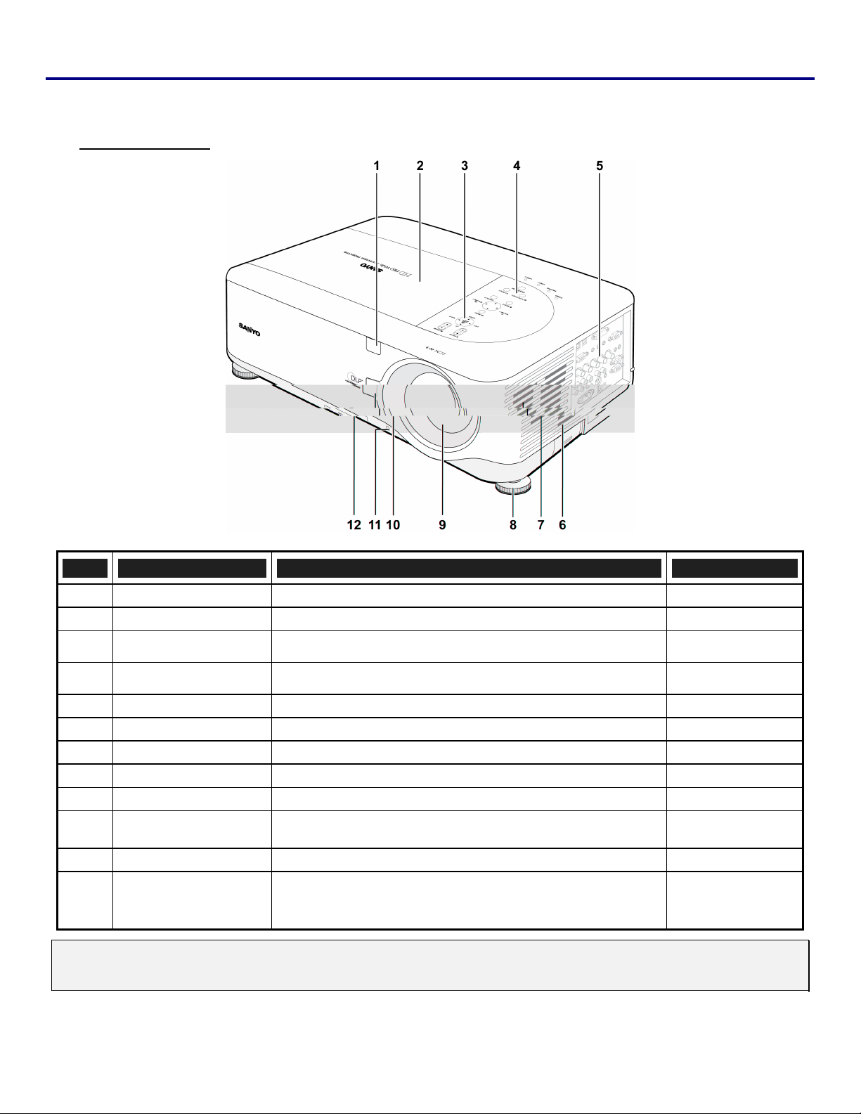
Part Names of the Projector
1. Introduction
Front-right view
ITEM LABEL DESCRIPTION SEE PAGE:
1.
2.
3.
4.
5.
6.
7.
8.
9.
10.
11.
12.
Important:
Grill openings on the projector allow for good air circulation, which keeps the projector lamp cool. Do not obstruct any of the grill
openings.
IR receiver Receiver for IR signal from remote control
Lamp cover Remove cover to replace lamp or color wheel
Lens control panel See Lens Controls
OSD control panel See OSD Controls and Status LEDS
I/O connector panel Connect various input devices
Intake vent Lamp cooling vent – do not obstruct
Speakers Built-in stereo speakers
Height adjuster Adjusts level of projector
Lens Remove lens cap before use
Lens release button Press the release button before removing the lens
Anti-Theft screw Prevent theft of the lens
Intake vent and front
filter
Keeps the front fan free of dust
– clean regularly for optimum performance
– do not obstruct
11
99
6
7
9
—
—
5
—
—
—
95
3
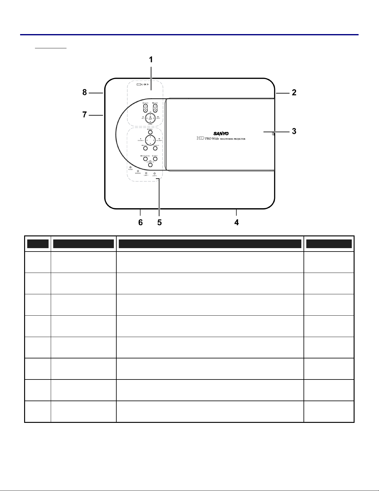
1. Introduction
Top view
ITEM LABEL DESCRIPTION SEE PAGE:
1.
2.
3.
4.
5.
6.
7.
Lens control panel See Lens Controls
Right-hand speaker Right-hand speaker
Lamp cover Remove cover to replace lamp or color wheel
Exhaust vent Exhaust vent – do not obstruct
OSD control panel See OSD Controls and Status LEDS
Rear intake vent Rear cooling intake – do not obstruct
Left intake vent Left-hand cooling intake – do not obstruct
6
—
99
—
7
—
—
8.
Left-hand speaker Left-hand speaker
—
4
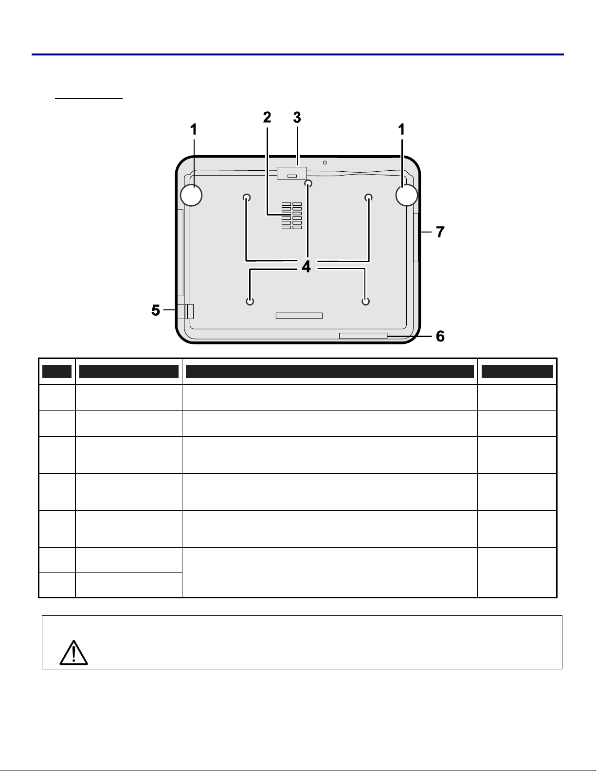
Bottom view
1. Introduction
ITEM LABEL DESCRIPTION SEE PAGES:
1.
2.
3.
4.
5.
6.
7.
Height adjusters Adjust projection height
Intake vent Color wheel cooling vent – do not obstruct
Front filter
Ceiling support holes
Security chain
opening
Rear filter
Side filter
Keep the fan free of dust – clean regularly for optimum perform-
ance
Contact your dealer for information on mounting the projector on
a ceiling
Attach anti-theft device – see Using the Physical Lock
Keep the fans free of dust – clean regularly for optimum per-
formance
38
—
95
—
54
95
CAUTION
With ceiling installation, use approved mounting hardware & M4 screws; maximum depth of screw: 12 mm; distance from ceiling/ wall: 20 cm (0.7 feet) for proper ventilation; distance from
feet) front and back of the projector
. For permanent installations, follow local codes.
5
fluorescent lamps: at least 1 m (3
1. Introduction
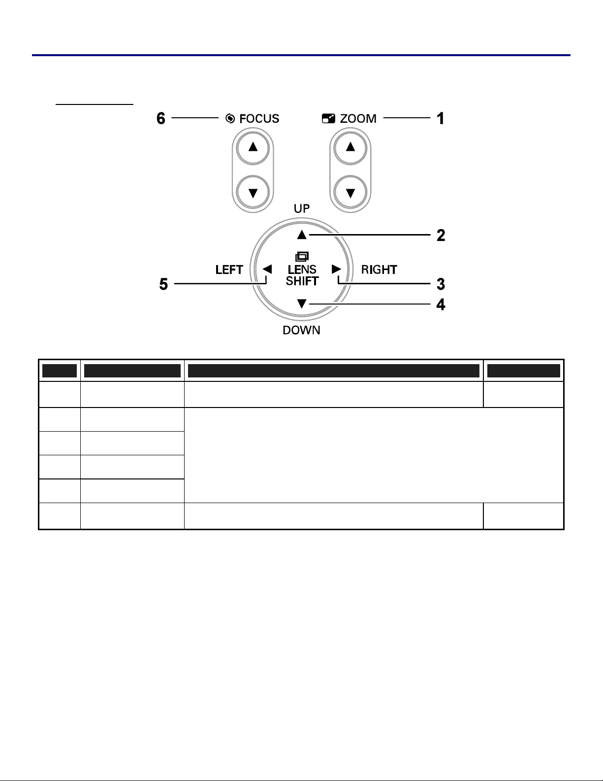
Top Features
Lens Controls
ITEM LABEL DESCRIPTION SEE PAGE:
1.
2.
3.
4.
5.
6.
ZOOM Increase/decrease projected image size
UP CURSOR
RIGHT CURSOR
Move image left, right, up, or down
DOWN CURSOR
LEFT CURSOR
FOCUS Focus the projected image
44
44
6
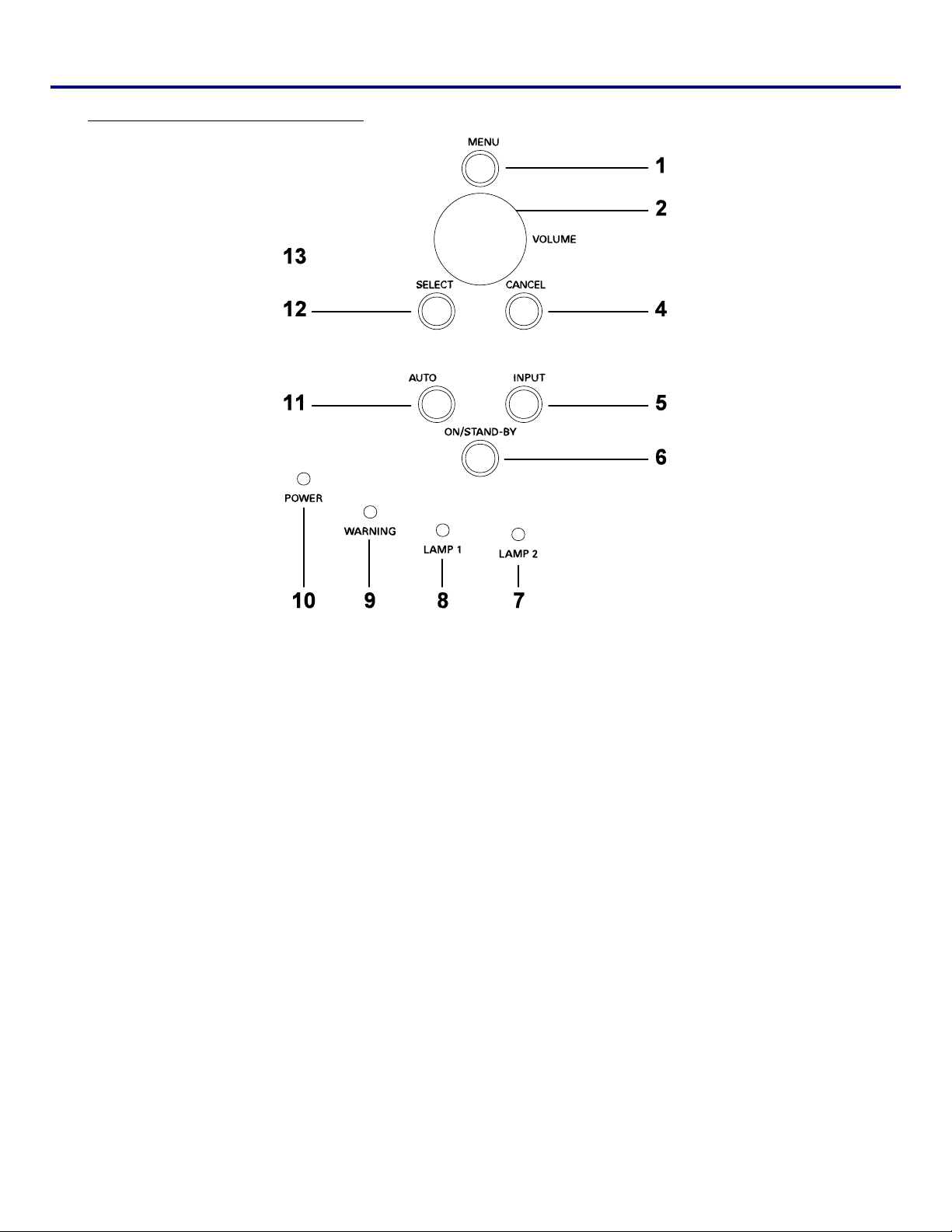
OSD Controls and Status LEDs
1. Introduction
7
1. Introduction
ITEM LABEL DESCRIPTION SEE PAGE:
8.
9.
10.
11.
12.
13.
LAMP 1 (LED) See Indicator Messages
WARNING (LED) See Indicator Messages
POWER (LED) See Indicator Messages
AUTO PC ADJ. Optimize image size, position, and resolution
SELECT Select or change settings in the OSD
LEFT
CURSOR/VOLUME
DECREASE
Decrease volume
102
102
102
39
55
40
8
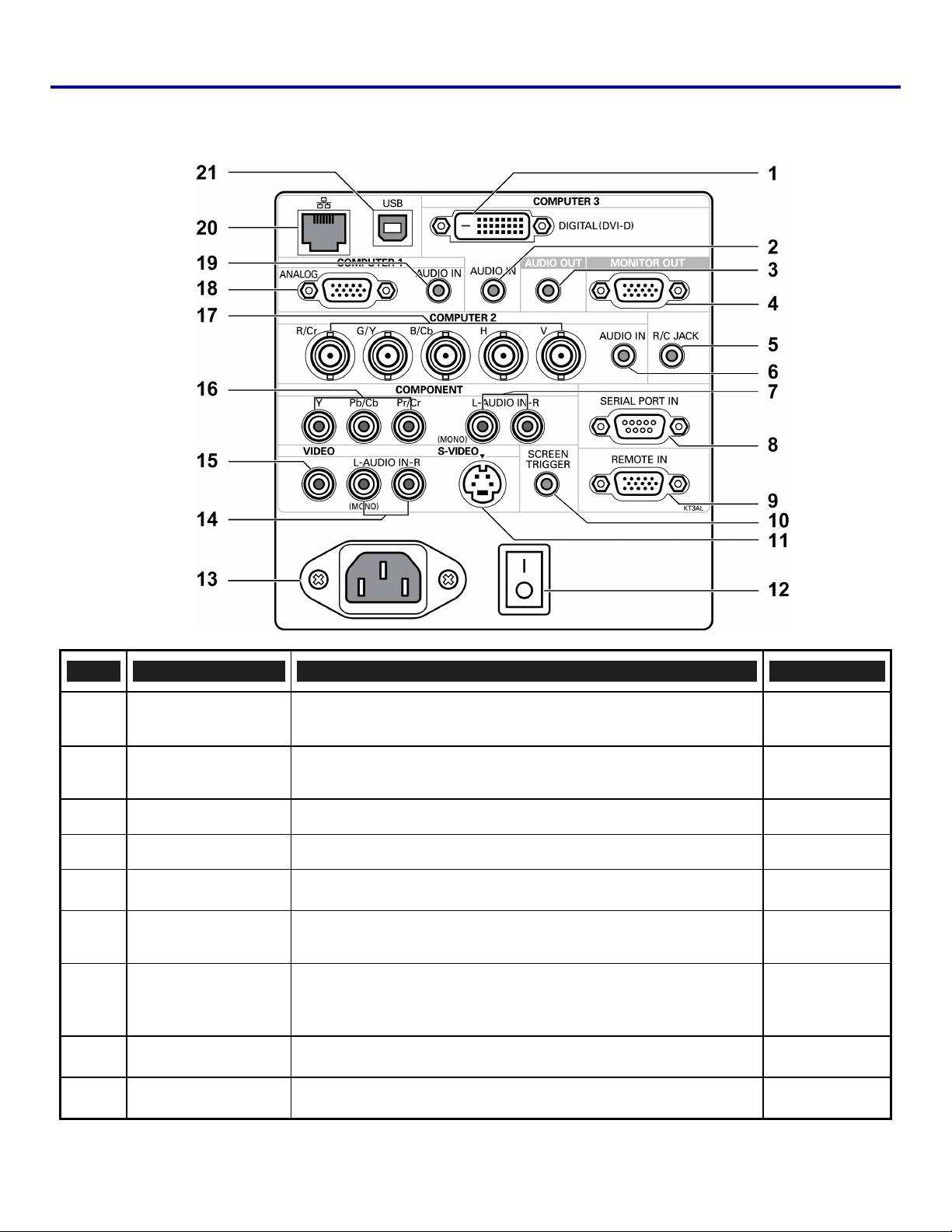
r Terminal Panel Features
1. Introduction
ITEM LABEL DESCRIPTION SEE PAGE:
1.
2.
3.
4.
5.
6.
7.
8.
COMPUTER 3 IN Connect the DVI-D cable (not supplied) from a computer
AUDIO IN
(COMPUTER 3)
AUDIO OUT Audio loop-thru
MONITOR OUT Connect to a monitor
R/C JACK Connect the remote to the projector
AUDIO IN
(COMPUTER 2)
AUDIO IN
[L(MONO)/R]
(COMPONENT)
SERIAL PORT IN Installation control
Connect the audio cable (not supplied) from the input device
Connect the audio cable (not supplied) from the input device
Connect an RCA audio cables (not supplied) from the input de-
vice right and left channels
26
—
—
—
15
—
—
115
9.
REMOTE IN For external control
123
9
1. Introduction
ITEM LABEL DESCRIPTION SEE PAGE:
10.
11.
12.
13.
14.
15.
16.
17.
When connected to the screen through
SCREEN
TRIGGER
S-VIDEO
POWER SWITCH Turn on/off the projector
AC IN Connect the supplied power cable
AUDIO IN
[L(MONO)/R]
(VIDEO)
VIDEO IN
COMPONENT IN
(Y, Cb/Pb, Cr/Pr)
COMPUTER 2 IN
(R/Cr, G/Y, B/Cb,
H, V)
cable, the screen deploy
tor. The screen retracts when the projector is powered off
(see notes below)
Connect a commercially available S-video cable from a video
device
Connect RCA audio cables (not supplied) from the input device
right and left channels. This audio jack is shared with S-Video
input.
Connect a composite video cable (not supplied) from a video de-
vice to the yellow RCA jack
Connect a component video enabled device
Connect RGBHV or Component signal from computer or com-
ponent video enabled device
s automatically on start up of the projec-
a commercially available
117
30
32,41
31
—
30
29
26
18.
19.
20.
21.
Note:
To use this feature, you must turn on the Screen Trigger function on the OSD.
Screen controllers are supplied and supported by screen manufacturers.
Do not use this jack for anything other than intended use. Connecting the wired remote control to the
Trigger mini jack causes damage to the remote control.
COMPUTER 1 IN Connect a VGA cable (supplied) from a computer
AUDIO IN
(COMPUTER 1)
LAN Connect a LAN cable (not supplied) from a computer
SERVICE
Connect the audio cable (not supplied) from the input device
Connect the USB cable (not supplied) from a computer. For ser-
vice personnel only.
26
—
—
10
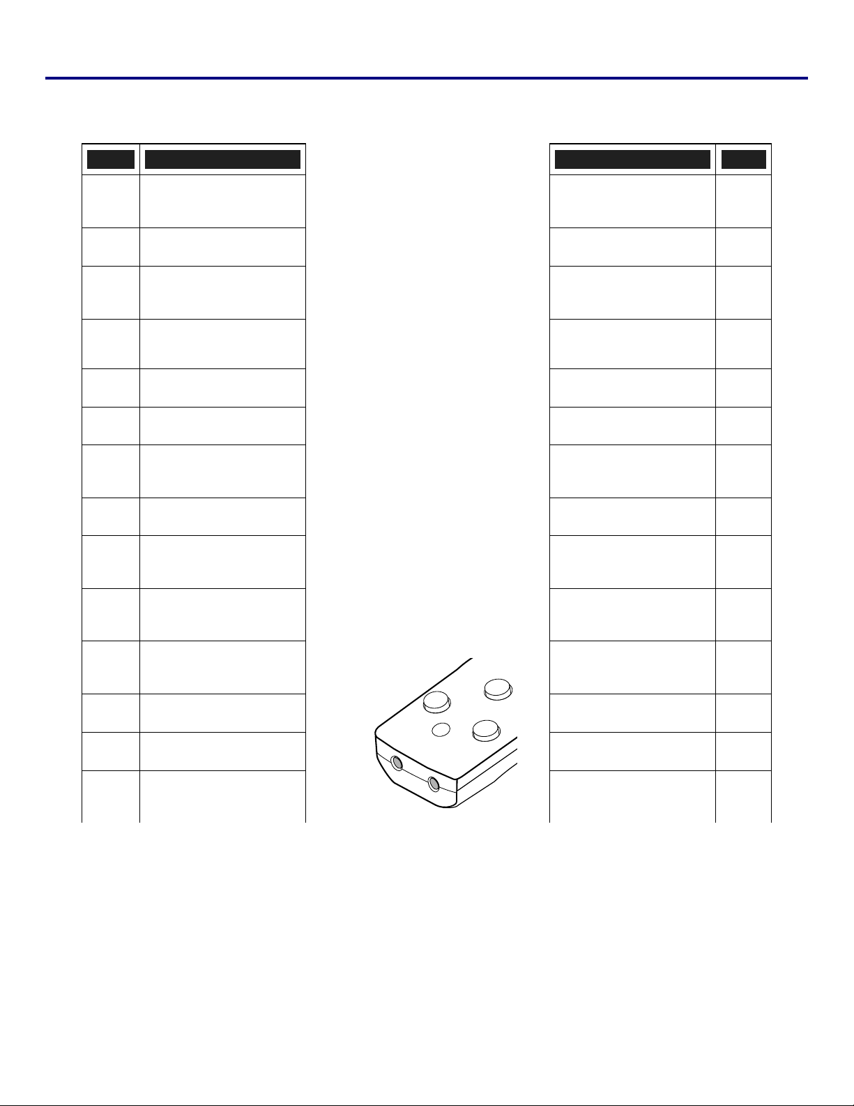
Part Names of the Remote Control
ITEM LABEL LABEL ITEM
1.
2.
3.
4.
ON
STAND-BY
LIGHT
Illuminate the remote panel.
MENU
Open or close the on-Screen
menu.
1. Introduction
NO SHOW
Temporarily turns off screen
image.
D. ZOOM -/+
Zoom in/out function.
AUTO PC
Automatically adjust the
computer image.
KEYSTONE
Correct keystone distortion.
15.
16.
17.
18.
5.
6.
7.
8.
9.
10.
11.
12.
13.
14.
CANCEL VOLUME -/+
VOLUME - COMPUTER 1
19.
20.
SELECT
Executes a selected menu
item
COMPUTER 2
VOLUME + COMPUTER 3
LENS SHIFT
Shift the lens up, down, right
and left.
FOCUS/ZOOM
Correct image distortion.
IMAGE
Select image mode
SCREEN
Select the screen size.
FREEZE
Freeze the picture.
LAMP CONTROL
Select a lamp mode.
COMPONENT
Select the component input
source.
S-VIDEO
Select the S-video input
source.
VIDEO
Select the video input
source.
IR TRANSMITTER
IR TRANSMITTER
REMOTE JACK
Connect a wired remote con-
trol.
21.
22.
23.
24.
25.
26.
27.
28.
11

1. Introduction
Important:
Avoid using the projector with bright fluorescent lighting turned on. Certain high-frequency fluorescent lights
can disrupt remote control operation.
1. Be sure nothing obstructs the path between the remote control and the projector. If the path between remote and projector is obstructed, you can bounce the remote signal off certain reflective surfaces such as
projector screens.
2. The buttons and keys on the projector have the same functions as the corresponding buttons on the remote control. This user’s manual describes the functions based on the remote control.
Note:
* To turn off the projector, press the STAND-BY button twice.
12
1. Introduction
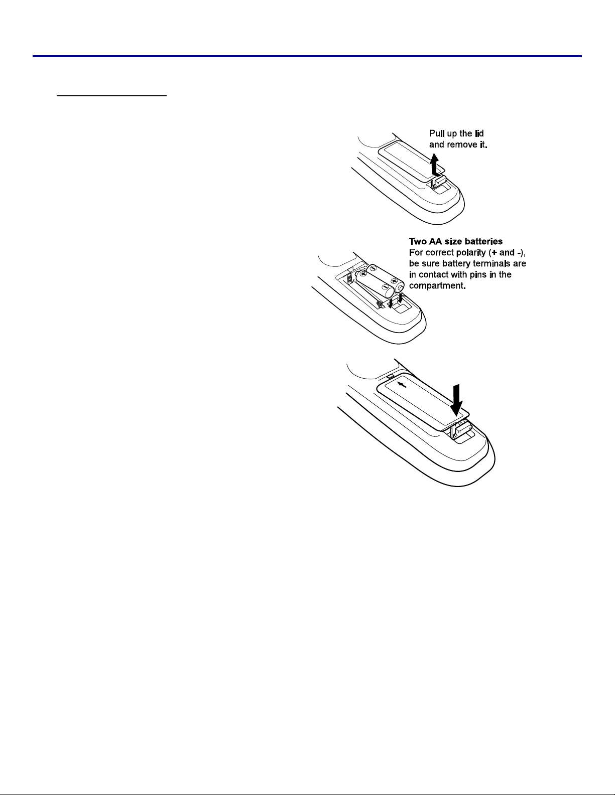
Battery Installation
The Remote Control unit included with the projector does not contain batteries, though batteries are supplied as part of the
complete package. To insert (or replace) the batteries, refer to the following guide.
1.
2.
3.
Remove the battery compartment cover
by squeezing the locking catch and slid-
ing the cover in the direction of the
arrow.
Insert the supplied batteries taking note
of the polarity (+/-) as shown.
Replace the cover locator, and then
click locking catch into place as shown.
13
1. Introduction
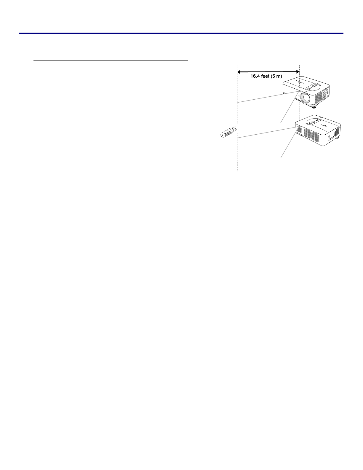
Operating Range for Wireless Remote Control
Point the remote control toward the projector (to Infrared Remote Receivers) when pressing the buttons. Maximum operating range for the
remote control is about 16.4 feet (5 m) and 60 degrees in front and rear
of the projector.
Infrared remote receivers are provided both in front and back of the projector. You can conveniently use both of the receivers.
Remote Control Precautions
The following precautions ensure that the remote operates correctly and
safely.
• Use two (2) AA or LR6 type alkaline batteries.
• Always replace batteries in sets.
• Do not use a new battery with a used one.
• Avoid contact with water or liquid.
• Do not expose the remote control to moisture or heat.
• Do not drop the remote control.
• If the battery has leaked on the remote control, carefully wipe the
case clean and install new batteries.
• Risk of an explosion if battery is replaced by an incorrect type.
• Dispose of used batteries according to the instructions.
14
1. Introduction
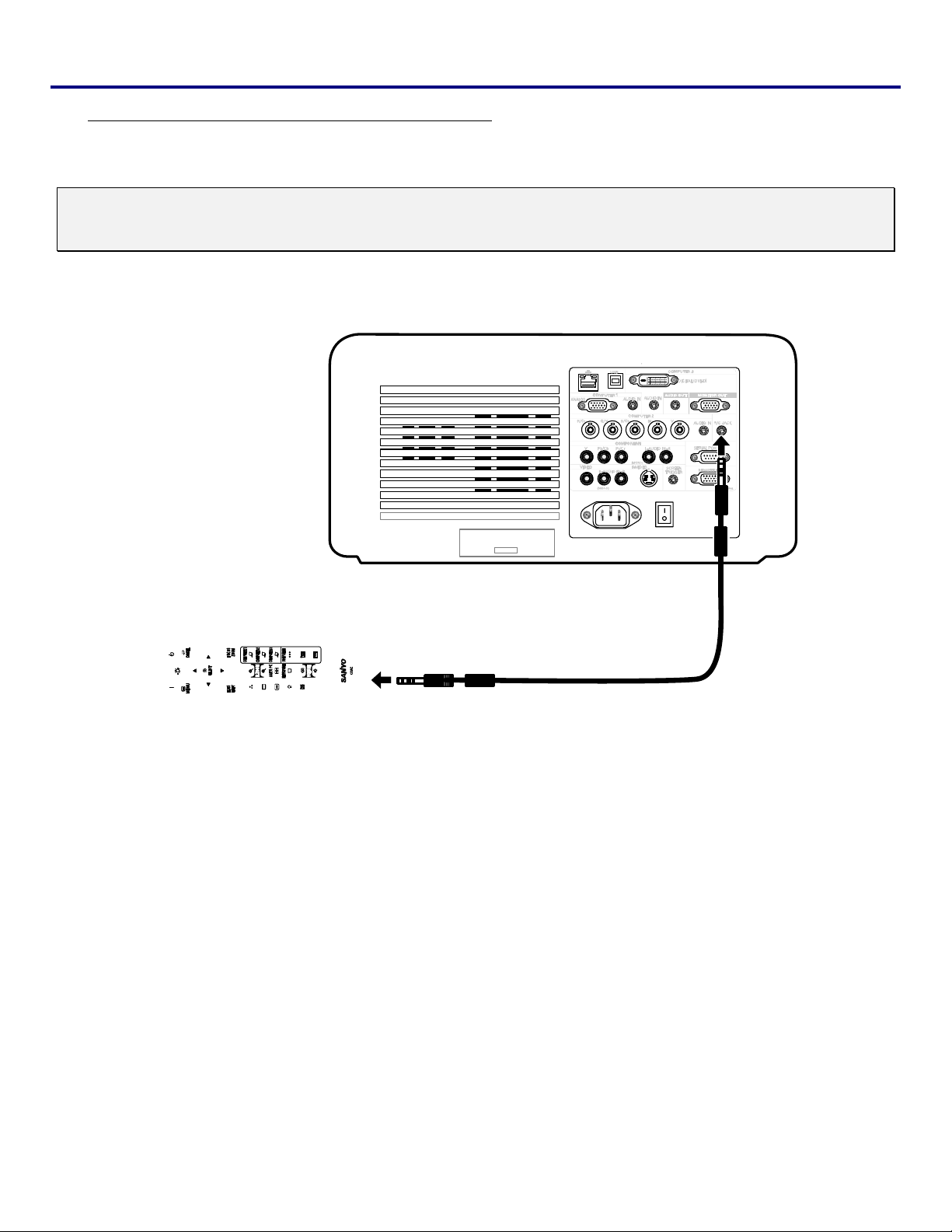
Using the Remote Control in Wired Operation
Connect the supplied remote cable to the R/C jack on the projector (see Terminal Panel Features on page 9) and the
other end to the remote jack on the remote control (see item 1, Part Names of the Remote Control on page 11).
Note:
Connecting the remote cable to the R/C jack on the terminal panel will make the wireless operation unavailable.
15
1. Introduction
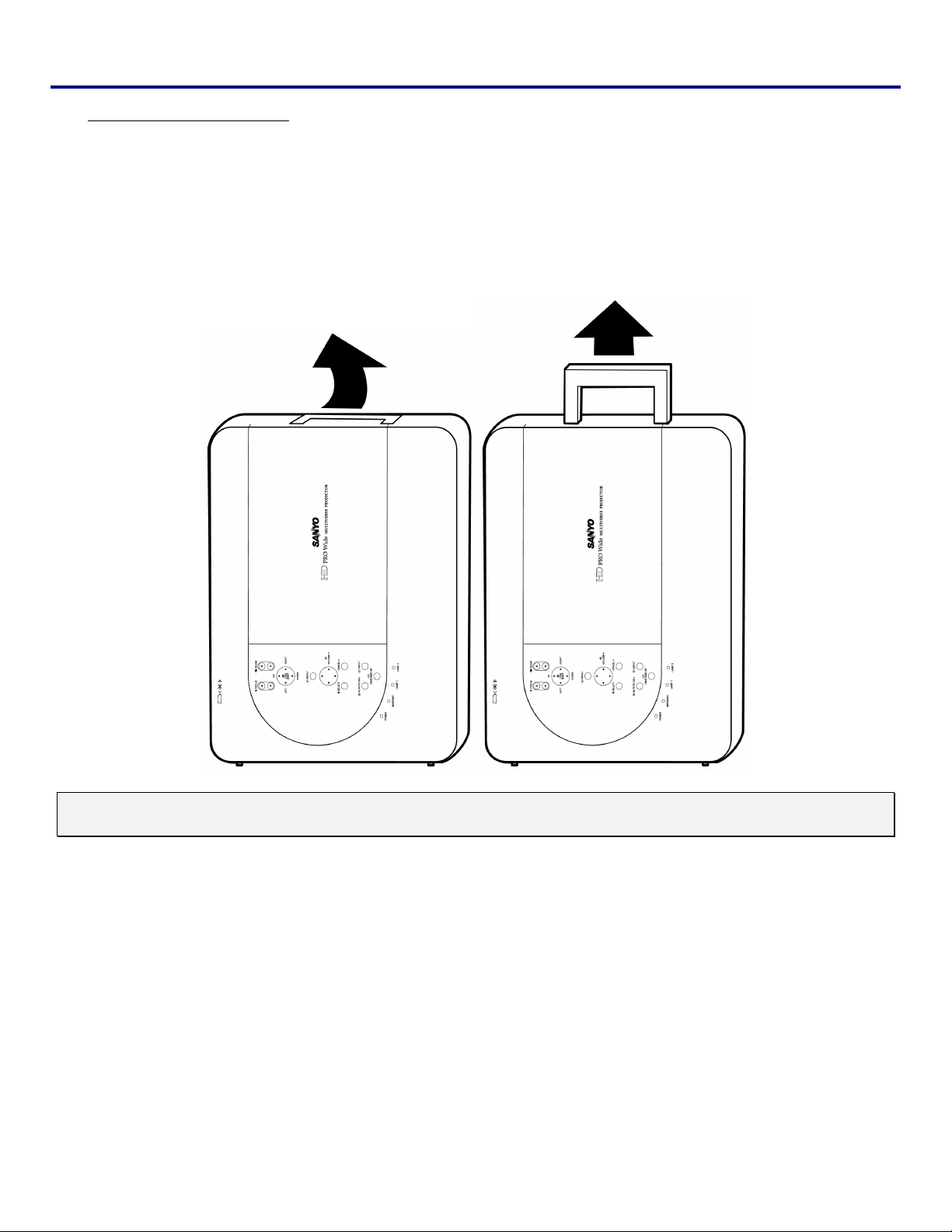
Carrying the Projector
Always carry your projector by the handle.
Before moving or carrying the projector, disconnect the power cable and any other cables that may be attached to it.
When moving the projector or when the projector is not in use, cover the lens with the lens cap.
To extend the projector handle, refer to the following guide.
1. Stand the projector on its end with the control panels at the bottom.
2. Lift the handle in the direction shown until it is fully extended.
Note:
Stand the projector on its end by lifting the cabinet. Do not use the handle to place the projector upright.
16
2. Installation and Connections
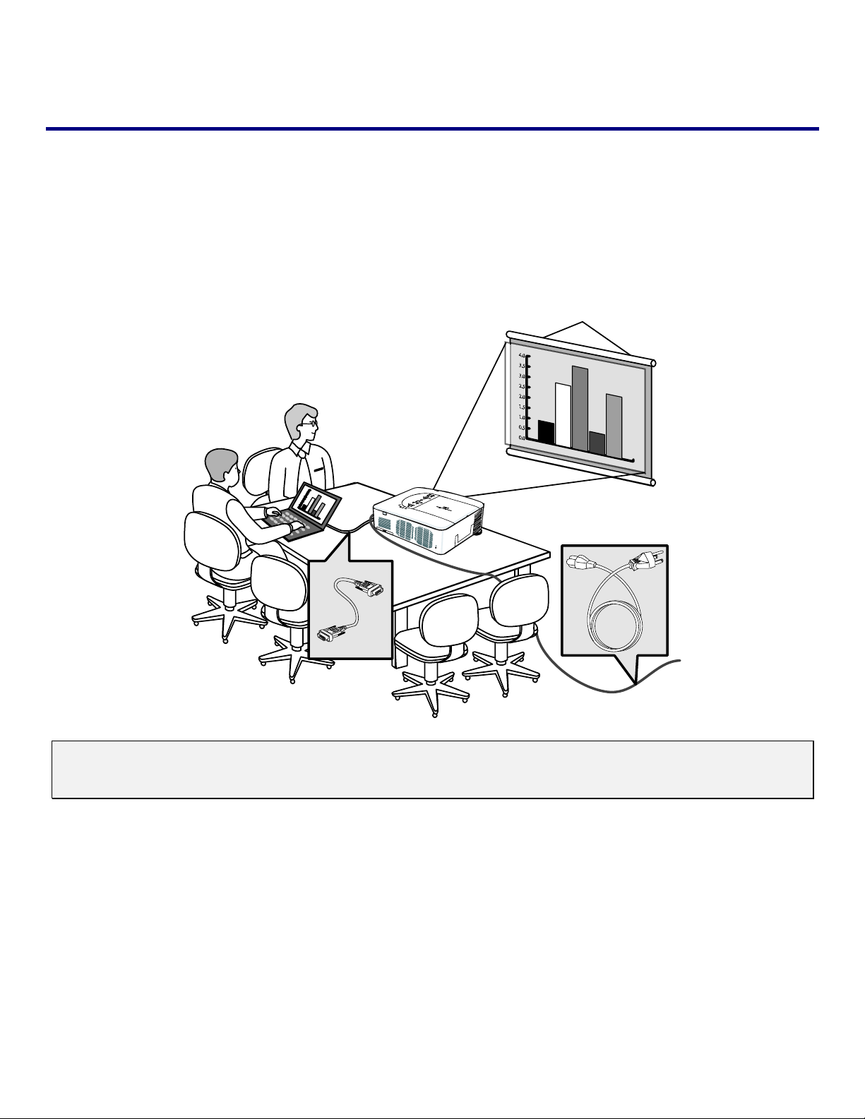
Setting Up the Screen and the Projector
This section briefly describes how to set up your projector and how to connect video and
audio sources.
Your projector is simple to set up and use. But before you get started, you must first:
• Set up a screen and the projector.
• Connect your computer or video equipment to the projector. See Making Connections on page 26.
• Connect the supplied power cable. See Connecting the Supplied Power Cable on page 31.
Note:
Ensure that the power cable and any other cables are disconnected before moving the projector. When
moving the projector or when it is not in use, cover the lens with the lens cap.
17
2. Installation and Connections
o Selecting a Location
Locating the projector correctly ensures optimum performance and a longer parts life.
Take note of the following when setting up the projector:
• The projector table or stand should be level and sturdy.
• Position the projector so that it is perpendicular to the screen.
• Ensure cables do not cause a trip hazard.
18
Installing or Removing the Optional Lens
• Do not shake or place excessive pressure on the projector or the lens components as the projector and
lens components contain precision parts.
• When shipping the projector with the optional lens, remove the optional lens before shipping the projector. The lens and the lens shift mechanism may encounter damage caused by improper handling during
CAUTION
transportation.
• Before removing or installing the lens, be sure to turn off the projector, wait until the cooling fans stop,
and turn off the main power switch.
• Do not touch the lens surface when removing or installing the lens.
• Keep fingerprints, dust or oil off the lens surface. Do not scratch the lens surface.
• Work on a level surface with a soft cloth under it to avoid scratching.
• If you remove and store the lens, attach the lens cap to the projector to keep off dust and dirt.
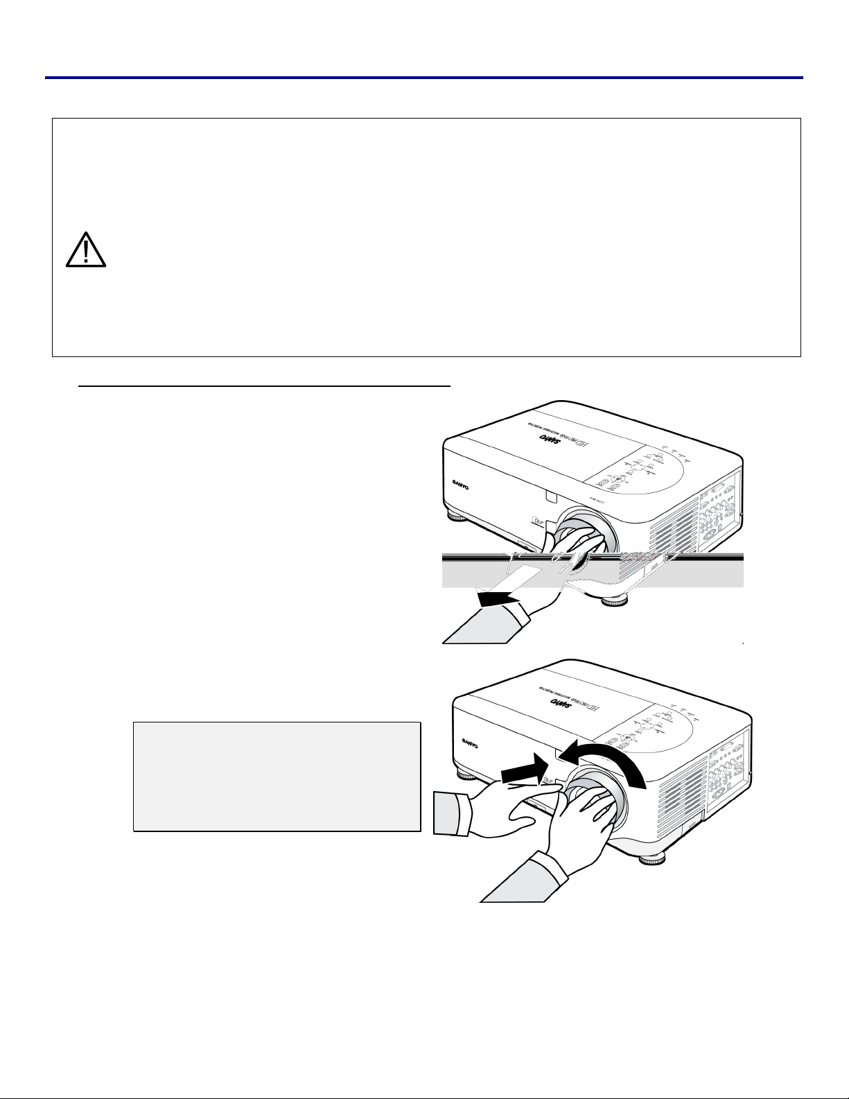
Removing the Existing Lens From the Projector
2. Installation and Connections
1.
2.
Pull out the lens cap.
Push the LENS RELEASE button all the way
in and rotate the lens counterclockwise.
The existing lens will be disengaged.
Note:
If the lens cannot be removed even by
using the LENS RELEASE button, the
anti-theft screw for lens may be in use
to secure the lens. If that is the case,
remove the anti-theft screw first.
19
2. Installation and Connections
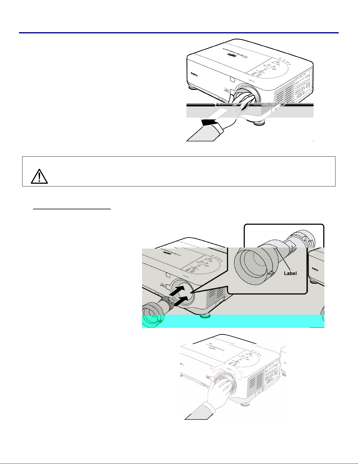
3.
CAUTION
Pull out the existing lens slowly.
When Installing the lens into the projector, be sure to remove the lens cap from the back of the optional
lens before installing the optional lens into the projector. Failure to do so will cause damage to the projector.
Installing the New Lens
Insert the lens label side up.
1.
Rotate the lens clockwise until it
2.
clicks into place.
20
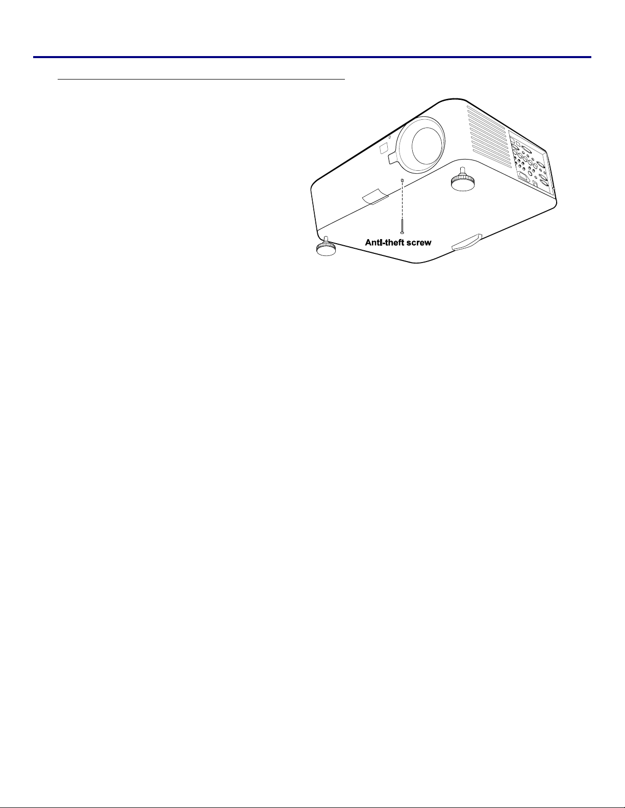
Installing the New Lens Using the anti-theft screw
Using the anti-theft screw to prevent theft of
the lens.
Tighten the supplied anti-theft screw on the
front bottom.
2. Installation and Connections
21

2. Installation and Connections
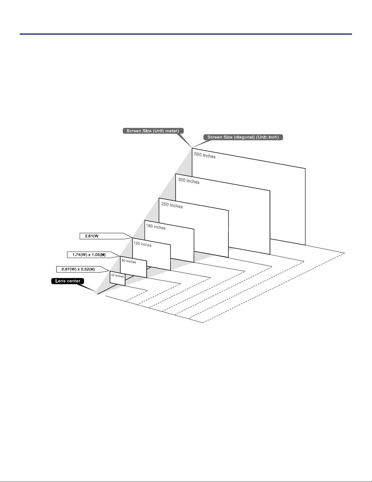
q Throw Distance and Screen Size
Example of LNS-S40:
The further your projector is from the screen or wall, the larger the image. The minimum size the image can be is approximately 40 inches (1 m) measured diagonally when the projector is roughly 71 inches (1.8 m) from the wall or screen. The
largest the image can be is 500 inches (12.7 m) when the projector is about 915 inches (23.2 m) from the wall or screen.
Screen Size LNS-W41 LNS-W40 LNS-S40
Diagonal Width Height
0.77 1.33 - 1.79 1.78 - 2.35
Distance
[inches] [m] [inches] [m] [inches] [m] [inches] [m] [inches] [m] [inches] [m]
40 1.02 34.3 0.87 20.5 0.52 45.4 - 61.8 1.15 - 1.57 60.9 - 81.0 1.55 - 2.06
50 1.27 42.9 1.09 25.6 0.65 33.5 0.85 57.2 - 77.7 1.45 - 1.97 76.7 - 101.9 1.95 - 2.59
60 1.52 51.6 1.31 30.7 0.78 40.5 1.03 69.0 - 93.6 1.75 - 2.38 92.5 - 122.8 2.35 - 3.12
67 1.70 57.6 1.47 34.3 0.87 45.4 1.15 77.3 - 104.7 1.96 - 2.66 103.6 - 137.4 2.63 - 3.49
72 1.83 61.9 1.58 36.8 0.94 48.9 1.24 83.2 - 112.7 2.11 - 2.86 111.5 - 147.9 2.83 - 3.76
80 2.03 68.5 1.74 41.3 1.05 54.5 1.38 92.7 - 125.4 2.35 - 3.19 124.2 - 164.6 3.15 - 4.18
84 2.13 71.9 1.83 43.4 1.10 57.3 1.46 97.4 - 131.8 2.47 - 3.35 130.5 - 172.9 3.31 - 4.39
90 2.29 77.1 1.96 46.5 1.18 61.5 1.56 104.5 - 141.3 2.65 - 3.59 140.0 - 185.4 3.56 - 4.71
100 2.54 85.8 2.18 51.6 1.31 68.5 1.74 116.3 - 157.2 2.95 - 3.99 155.8 - 206.3 3.96 - 5.24
120 3.05 102.8 2.61 61.8 1.57 82.5 2.10 140.0 - 189.0 3.56 - 4.80 187.4 - 248.1 4.76 - 6.30
150 3.81 128.7 3.27 77.2 1.96 103.5 2.63 175.5 - 236.7 4.46 - 6.01 234.9 - 310.7 5.97 - 7.89
180 4.57 154.3 3.92 92.5 2.35 124.5 3.16 211.0 - 284.4 5.36 - 7.22 282.3 - 373.3 7.17 - 9.48
200 5.08 171.7 4.36 102.8 2.61 138.5 3.52 234.6 - 316.2 5.96 - 8.03 313.9 - 415.1 7.97 - 10.54
210 5.33 180.3 4.57 107.9 2.74 246.4 - 332.1 6.26 - 8.44 329.7 - 436.0 8.38 - 11.07
240 6.10 206.0 5.24 123.4 3.13 281.9 - 379.8 7.16 - 9.65 377.2 - 498.6 9.58 - 12.66
261 6.63 224.1 5.69 134.2 3.41 306.8 - 413.2 7.79 - 10.50 410.4 - 542.4 10.42 - 13.78
270 6.86 231.8 5.89 138.8 3.52 317.4 - 427.5 8.06 - 10.86 424.6 - 561.2 10.79 - 14.25
300 7.62 257.1 6.53 154.3 3.92 352.9 - 475.2 8.96 - 12.07 472.1 - 623.8 11.99 - 15.85
350 8.89 300.0 7.62 180.0 4.57 412.0 - 554.8 10.47 - 14.09 551.2 - 728.2 14.00 - 18.50
400 10.16 342.9 8.71 205.9 5.23 471.2 - 634.3 11.97 - 16.11 630.2 - 832.6 16.01 - 21.15
450 11.43 385.8 9.80 231.6 5.88 530.3 - 713.8 13.47 - 18.13 709.3 - 937.0 18.02 - 23.80
500 12.70 428.7 10.89 257.1 6.53 589.5 - 793.3 14.97 - 20.15 788.4 -
1041.4
20.02 - 26.45
22

Screen Size LNS-T40 LNS-T41
Diagonal Width Height
[inches] [m] [inches] [m] [inches] [m] [inches] [m] [inches] [m]
40 1.02 34.3 0.87 20.5 0.52 75.7 - 155.0 1.92 - 3.94 151.7 - 289.8 3.85 - 7.36
50 1.27 42.9 1.09 25.6 0.65 95.7 - 194.7 2.43 - 4.95 190.9 - 363.5 4.85 - 9.23
60 1.52 51.6 1.31 30.7 0.78 115.6 - 234.5 2.94 - 5.96 230.2 - 437.3 5.85 - 11.11
67 1.70 57.6 1.47 34.3 0.87 129.6 - 262.4 3.29 - 6.66 257.7 - 488.9 6.55 - 12.42
72 1.83 61.9 1.58 36.8 0.94 139.6 - 282.3 3.55 - 7.17 277.3 - 525.8 7.04 - 13.36
80 2.03 68.5 1.74 41.3 1.05 155.6 - 314.1 3.95 - 7.98 308.8 - 584.9 7.84 - 14.86
84 2.13 71.9 1.83 43.4 1.10 163.6 - 330.0 4.15 - 8.38 324.5 - 614.4 8.24 - 15.60
90 2.29 77.1 1.96 46.5 1.18 175.5 - 353.9 4.46 - 8.99 348.0 - 658.6 8.84 - 16.73
100 2.54 85.8 2.18 51.6 1.31 195.5 - 393.6 4.97 - 10.00 387.3 - 732.4 9.84 - 18.60
120 3.05 102.8 2.61 61.8 1.57 235.4 - 473.2 5.98 - 12.02 465.9 - 880.0 11.83 - 22.35
150 3.81 128.7 3.27 77.2 1.96 295.3 - 592.6 7.50 - 15.05 583.7 180 4.57 154.3 3.92 92.5 2.35 355.2 - 711.9 9.02 - 18.08 701.5 200 5.08 171.7 4.36 102.8 2.61 395.2 - 791.5 10.04 - 20.10 780.0 210 5.33 180.3 4.57 107.9 2.74 415.1 - 831.3 10.54 - 21.11 819.3 240 6.10 206.0 5.24 123.4 3.13 475.0 - 950.6 12.07 - 24.15 937.1 261 6.63 224.1 5.69 134.2 3.41 517.0 270 6.86 231.8 5.89 138.8 3.52 534.9 300 7.62 257.1 6.53 154.3 3.92 594.8 350 8.89 300.0 7.62 180.0 4.57 694.7 400 10.16 342.9 8.71 205.9 5.23 794.5 450 11.43 385.8 9.80 231.6 5.88 894.3 500 12.70 428.7 10.89 257.1 6.53 994.1 -
2.22 - 4.43 4.43 - 8.3
Distance
1101.3
14.83 - 27.97
1322.6
17.82 - 33.59
1470.2
19.81 - 37.34
1543.9
20.81 - 39.22
1765.3
23.80 - 44.84
1034.1
1069.9
1189.3
1388.2
1587.1
1786.0
1984.9
13.13 - 26.27
13.59 - 27.18
15.11 - 30.21
17.64 - 35.26
20.18 - 40.31
22.72 - 45.37
25.25 - 50.42
1019.6 -1920.2
1054.9 -1986.6
1172.8-2207.9
1369.1 -2576.8
1565.5 - 2945.7
1761.9 - 3314.6
1958.2 - 3683.4
25.90 - 48.77
26.80 - 50.46
29.79 - 56.08
34.78 - 65.45
39.76 - 74.82
44.75 - 84.19
49.74 - 93.56
2. Installation and Connections
CAUTION
Ceiling installation must be done by a qualified professional. Contact your SANYO dealer for more
information.
It is not recommended you install the projector yourself.
Only use the projector on a solid, level surface. Serious injury and damage can occur if the projector
is dropped.
Do not use the projector in an environment where extreme temperature occurs. The projector must
be used at temperatures between 41 degrees Fahrenheit (5 degrees Celsius) and 104 degrees Fahrenheit (40 degrees Celsius).
Screen damage will occur if the projector is exposed to moisture, dust or smoke.
Do not cover the vents on the projector. Proper ventilation is required to dissipate heat. Damage to
the projector will occur if the vents are covered.
23

2. Installation and Connections
Installing the Optional Color Wheel
The PDG-DWT50L projector comes with a four-segment color wheel installed. An additional six-segment color wheel is optional. To replace the color wheel (located under the lamp cover adjacent to lamp 1) refer to the following guide.
Note:
Wait until the lamp house and the color wheel cool off.
1.
2.
3.
Loosen the captive screw (A)
on the lamp cover.
Remove the lamp cover by
sliding it in the direction of
the arrow (B).
Unscrew the retaining screws
(x 4) on the four-segment
color wheel.
24

2. Installation and Connections
4.
Lift the color wheel in the di-
rection shown.
25

2. Installation and Connections
7.
Align the lamp cover (A) with
the arrow mark on the cabinet
and slide it into place.
26

2. Installation and Connections
2. Turn on the projector and select the chosen method of connection from the source menu before turning on the
PC (see Selecting an Input Source on page 34).
3. Turn on the PC.
Note:
Failure to follow the above steps may not activate the digital output of the graphics card resulting in no picture being displayed. Should this happen, restart your PC.
27

2. Installation and Connections
Connecting an External Monitor
Connect an external monitor to the projector through RGB out connections as shown below
(see item 4, Terminal Panel Features on page 9)
28

2. Installation and Connections
Connecting Your DVD Player with Component Output
To connect a DVD Player to the projector, refer to the following guide.
1. Connect the DVD Player to the projector as shown below before turning on the Player or the projector.
2. Turn on the projector and select Component from the source menu before turning on the DVD Player
(see Selecting an Input Source on page 34).
3. Turn on the DVD Player.
Note:
Refer to your DVD player's user's manual for more information about your DVD player's video output requirements.
29

2. Installation and Connections
Connecting Your VCR or Laser Disc Player
To connect your VCR or Laser Disc Player, refer to the following diagram.
30

2. Installation and Connections
Connecting the Supplied Power Cable
This projector uses nominal input voltages of 100–120V or 200–240V AC and it automatically selects the correct input voltage. It is designed to work with single-phase power systems having a grounded neutral conductor. To reduce the risk of
electrical shock, do not plug into any other type of power system. If you are not sure of the type of power being supplied,
consult your authorized dealer or service station. Connect the projector with all peripheral equipment before turning the
projector on.
CAUTION
For safety, unplug the AC power cord when the projector is not in use. When the projector is connected to an outlet with the AC power cord, it is in stand-by mode and consumes a small amount of
electrical power.
NOTE ON THE POWER CORD
The AC power cord must meet the requirements of the country where you are utilizing the projector. Confirm the AC plug
type with the chart below. The proper AC power cord must be used. If the supplied AC power cord does not match your AC
outlet, contact your sales dealer.
Note:
Make sure that the prongs are fully inserted into both the AC IN and the wall outlet.
CAUTION
Ensure that the cables do not create a trip hazard.
31

3. Projecting an Image (Basic Operation)
Turning on the Projector
Once the projector is correctly located and the power cable and other connections are in place, it is important that the projector is powered on correctly in order to avoid damage to components and unnecessary wear and tear. Refer to the
following guide to power on the projector.
Connect the power cable (A). Press the
1.
main power switch to the on ( I ) posi-
tion as shown (B). The power LED
lights orange and warning LED lights
green.
B
Press the On/Standby button once (see
2.
OSD Controls and Status LEDS on
page 7). The power LED lights green
and the internal cooling fan starts.
After approximately 10 seconds, the
3.
power LED flashes intermittently green.
The Lamp1 and Lamp2 LEDs light
4.
green and the Power LED flashes more
rapidly.
A
Once the power LED is lit a solid green,
5.
the projector is ready for use.
Note:
If any of the LEDs remain flashing or blink there may be a problem with the startup. Please refer to the
Troubleshooting section on page 102.
32

3. Projecting an Image (Basic Operation)
Note on Startup Screen (Menu Language Select screen)
In the first instance of powering on the projector, the language menu is displayed to select the default language.
Select the required default language using the ▲ or ▼ buttons on the OSD menu panel or the remote control unit and
press Select.
Note:
The language select screen only appears on the first instance of power on. All subsequent operations assume the selected default language. To change the default see page 74.
33

3. Projecting an Image (Basic Operation)
Selecting an Input Source
The Input Source can be selected from the projector's control panel or from the remote control unit. Refer to the following
guide to select the Input Source.
1.
2.
Note:
If an XGA signal is not correctly recognized, set “WXGA Mode” to off (see page 63).
Press Menu on the OSD control panel or on the remote
control unit to display the Main Menu. Scroll to the
Input menu using ▲or▼ and press Select.
Note:
Return to the projected image by pressing Cancel
twice.
Select the required source using ▲or▼ and press
Select.
To check if the signal is recognized, go to “Input” under “Information” menu (see page 90).
34

3. Projecting an Image (Basic Operation)
Adjusting the Picture Position and Picture Size
The Picture Position and Picture Size can be adjusted manually from the lens control panel or from the remote control unit.
Refer to the following guides to adjust Picture Position manually.
Adjusting Picture Position Manually
1.
2.
Press the Select keypad in any direction to
bring up the Lens Shift window.
Press the directional key as required to
shift the image. Releasing the
directional arrow will
re-center the cursor.
3.
To alter the picture size, press Menu and
select the Adjust menu using ▲or▼. Press
Select to open the Adjust menu. Press
◄or► to select Image Options followed
by ▲or▼ to select Screen. Press
Select.
35

3. Projecting an Image (Basic Operation)
4.
5.
The Screen window is displayed. Select
the desired picture size using ▲or▼ and
press Select.
When finished, press Cancel to return to
the projected image.
Lens Shift Adjustable Range
The adjustable range for lens shift is tabulated below and subject to the conditions listed.
Note:
The drawings below apply to the standard lens (LNS-S40) only.
36

From the Remote Control Unit
Press the Lens Shift button to bring up the
1.
Lens Shift window.
Press the directional keys as required to
2.
shift the image. Releasing the directional
arrow will re-center the cursor.
3. Projecting an Image (Basic Operation)
To alter the picture size, press the Screen
3.
button to display the Screen window.
Select the desired picture size using ▲or▼
4.
and press Select.
When finished, press Cancel to return to
5.
the projected image.
37

3. Projecting an Image (Basic Operation)
Adjusting the Projector Level
1.
2.
To raise the level of the projector, twist the adjust-
ers clockwise.
To lower the level of the projector, lift the projector
and twist the adjusters counter clockwise.
38

Optimizing an RGB Image Automatically
3. Projecting an Image (Basic Operation)
Adjusting the Image Using AUTO PC ADJ.
To optimize an RGB image automatically refer to the following guide.
Press the AUTO PC button on the remote control (see item 17, Part Names of the Remote Control on page 11) or the
AUTO PC ADJ. button on the OSD control panel to optimize an RGB image automatically.
This adjustment may be necessary when you connect your computer for the first time.
39

3. Projecting an Image (Basic Operation)
Adjusting Volume Up and Down
The volume can be adjusted from the OSD Control Panel or with the Remote Control unit. Refer to the following as a guide.
Press the Volume +/- buttons on the remote
1.
control or the ◄ ► buttons on the OSD con-
trol panel. The volume level is displayed on
screen.
Use the Volume +/- buttons or the ◄ ► but-
2.
tons on the OSD control panel to adjust the
level.
40

3. Projecting an Image (Basic Operation)
Turning off the Projector
Once the projector is no longer required, it is important to shut it down correctly to avoid damage or unnecessary wear and
tear to the projector.
• Do not unplug the power cable from the wall outlet or projector when the projector is powered on.
CAUTION
Refer to the following guide to shut down the projector.
Doing so can cause damage to the AC IN connector of the projector and (or) the prong plug of the
power cable. To turn off the AC power supply when the projector is powered on, use a power strip
equipped with a switch and a breaker.
• Do not turn off the AC power supply within 10 seconds of making adjustment or setting changes
and closing the menu. Doing so can cause loss of adjustments and settings and return to default.
1.
2.
3.
4.
Press the On/Standby button once. The Power Off
window displays.
Press the On/Standby button or Select again on the
OSD control panel or remote control to verify
power off.
The cooling fans continue to operate (cooling-off
time).
The cooling fans stop operating when the projector
turns off.
The projector enters Standby mode and the power
LED lights orange.
Press the Main Power switch to the off position (O)
to turn off the projector.
41

3. Projecting an Image (Basic Operation)
About Direct Power Off
The projector has a feature called "Direct Power Off". This feature allows the projector to be turned off (even when projecting an image)
using a power strip equipped with a switch and a breaker.
Note:
Before using Direct Power Off, be sure to allow at least 20 minutes immediately after turning on the projector
and starting to display an image.
After Use
Preparation: Make sure that the projector is turned off.
1. Unplug the power cable.
2. Disconnect any other cables.
3. Return the height adjusters to their original, minimum position.
4. Cover the lens with the lens cap.
42

43

4. Convenient Features
Adjusting the Focus/Zoom Manually
The focus and zoom can be adjusted manually from the projector focus/zoom panel or from the remote control unit. Refer
to the following guides to adjust the focus and zoom manually.
Adjusting by Using the OSD Control Panel
1.
2.
3.
Press the Focus or Zoom button
on the projector panel to display
the appropriate window.
Adjust the Focus/Zoom using the
increase and decrease buttons as
required.
Press Cancel to return to the pro-
jected image.
44

4. Convenient Features
Changing Lamp Mode
The projector has two lamp modes available, Normal and Eco. The Normal mode is used for everyday standard projection, whereas the Eco mode is used for saving power and lamp life. To change the Lamp Mode, refer to the following
guides.
Changing Lamp Mode by Using the Projector's OSD Control Panel
Press Menu on the projector's OSD control panel to dis-
1.
play the Main Menu. Scroll to the
Setting menu using ▲or▼ and press Select.
Select the Basic tab using ◄or► and select Lamp con-
2.
trol using ▲or▼. Press Select.
3.
From the Lamp control window, select Normal or Eco
using ▲or▼. Select OK and press Select.
45

4. Convenient Features
Changing Lamp Mode by Using the Remote Control
Press the Lamp control button on the remote control to ac-
1.
cess the Lamp control menu.
From the Lamp control window, select Normal or Eco us-
2.
ing ▲or▼. Move the cursor to OK and press Select.
Note:
When the projector is in Eco mode, brightness may be affected.
Normal Mode: 100% Brightness
Eco Mode: approx. 85% Brightness
46

4. Convenient Features
Getting Information
The Information screen provides details on the life of consumable items within the projector as well as other information
such as software version. To access the Information screen, refer to the following guide.
1.
2.
3.
Press Menu on the projector's OSD control
panel or remote control to display the Main
Menu. Scroll to the Information menu using
▲or▼ and press Select.
The Usage time menu is displayed as the de-
fault view. The menu items in this screen are
for display and cannot be modified.
Press Cancel to return to the projected image.
47

4. Convenient Features
Adjusting Position/Total Dots/Fine Sync
The Position/Total dots/Fine sync and Keystone Correction can be adjusted manually from the projector's control panel or
from the remote control unit. Refer to the following guides to adjust the Keystone Distortion manually.
Adjusting Position/Total Dots/Fine Sync by using the OSD Control Panel
Press the Menu button to display the Main
1.
menu. Select the Adjust menu using ▲or▼
and press Select to display the
Adjust menu.
From the Adjust menu, press ◄or► to select
2.
Image Options and scroll using ▲or▼ to
Horizontal, Vertical, Total dots, or Fine
sync.
Adjust the Horizontal, Vertical, Total dots,
3.
or Fine sync sliding bars using the select
▲▼◄► buttons.
Press Cancel to return to the projected image.
4.
48

Correcting Keystone by Using the Remote Control
Press the Keystone but-
1.
ton to display the
Keystone window.
4. Convenient Features
Adjust the Horizontal
2.
and Vertical sliding bars
using the select ▲▼◄►
buttons.
Adjust the slide bars until
3.
the screen trapezoid is a
regular shape (see dia-
gram).
Press Cancel to return to
4.
the projected image.
Note:
Holding down the Keystone button for 2 seconds resets the default keystone values.
49

4. Convenient Features
ADJUSTMENT HORIZONTAL VERTICAL
Keystone Max. +/– 35° approx. Max. +/– 40° approx.
The following are conditions under which the maximum angle is achieved:
When the standard lens (LNS-S40) is used
When the lens shift is set to H for center and V for 0.5 shift.
When the lens shift is used and yet you do not get the above-mentioned condition (H for center and V for 0.5 shift),
you cannot adjust the keystone correctly.
Image is projected in Wide mode
Resolution is WXGA
Note:
Higher resolution than WXGA narrows the adjustable range.
Menu items should be set as follows:
pect Ratio ........... 15:9
As
Horizontal and Vertical are adjusted separately.
A combination of both adjustments narrows the adjustable range.
50

4. Convenient Features
Preventing the Unauthorized Use of the Projector
The projector has a built-in security feature to lock the OSD control panels and deny remote control operation. The security
feature has no default keyword; in the first instance of enabling the security feature, the user must define a keyword.
Locking the Projector
To setup the security keyword, refer to the following guide.
1.
51

4. Convenient Features
4.
5.
CAUTION
The PIN code window is displayed. Enter a
PIN code between 4 and 10 characters using
▲▼◄►. The PIN code characters change
to “
Once a successful PIN code is entered, a
confirmation screen is displayed. Enter the
same password as the previous step and
write it down for later reference. Press
Select. A security activation message is displayed. Select Cancel to return to the
Setting menu or select OK to enable secu-
rity.
”. Press Select.
*
When you have set or changed the PIN code, take a memo and keep it securely. If you forget your
PIN code, the projector can no longer be started. Contact your dealer or the service center.
While the projector is locked with the PIN code...
Put on the label below (supplied) in a prominent place of the projector's body while it is locked with a PIN code.
52

Unlocking the Projector
To unlock the projector, refer to the following guide.
When the projector is locked, either by re-
1.
quest during operation or at start up, the
locked message is displayed.
To unlock the projector, press Menu on the
2.
control panel or remote control. The PIN
code window is displayed. Enter the previ-
ously defined PIN code to activate the
projector.
4. Convenient Features
53

4. Convenient Features
Using the Physical Lock
For security and authorized usage, the projector comes with two types of security features, the Kensington Lock and the
Security Chain Lock.
Using the Kensington Lock
If you are concerned about security, attach the projector to a permanent object with the
Kensington slot and a security cable.
Using the Security Chain Lock
In addition to the password protection function and the Kensington lock, the security chain opening helps protect the
projector from unauthorized use.
See the following illustration.
54

5. Using On-Screen Display
Using the Menus
The projector has an On-Screen Display (OSD) that lets you make image adjustments and change various settings.
Navigating the OSD
You can use the remote control or the buttons on the top of the projector to navigate and make changes to the OSD. The
following illustration shows the corresponding buttons on the remote control and on the projector.
To open the OSD, press the Menu but-
1.
ton on the OSD control panel or remote
control. There are six initial menus.
Press the cursor ▲or▼ buttons to
move through the initial menus and
Select to enter the desired menu.
55

5. Using On-Screen Display
Press the cursor ◄ or ► button to
2.
move through secondary menus.
Press ▲or▼ to select menu items and
3.
◄or► to change values for settings.
Press Select to confirm the new setting.
Press Cancel to close the OSD or leave
4.
a submenu.
56

Menu Tree
The gray shaded areas indicate factory default settings.
5. Using On-Screen Display
MENU
Input Computer 1, Computer 2, Computer 3, Component, Video, S-Video
Test pattern
Adjust Image Image select High-bright/Presentation/Video/Movie/Graphic/sRGB
Detail setting Basic Reference
Gamma Dynamic/Natural/Black detail
Brilliant color 1 to 3
White balance Red 1 to 100
Green 1 to 100
Blue 1 to 100
Contrast R 1 to 100
Contrast G 1 to 100
Contrast B 1 to 100
Color correction
Contrast 0 to 100
Brightness 0 to 100
Sharpness 0 to 31
Color 0 to 100
Tint 0 to 100
Reset
Overscan 0%/5%/10%/15%
PC Adj.
Horizontal ±50
Vertical ±25
Total dots ±50
Fine sync 0 to 63
WXGA Mode Off/On
Video Noise reduction Off/Low/Mid/High
3D Y/C separation Off/On
Progressive Off/Still/Normal/Movie
Color matrix Auto/RGB/SDTV/HDTV
Motion adaptive mode Motion adaptor/Field Jam/Scaled Field/Mixed Mode
Film Off/2-2/2-3 Auto/2-2 On/2-3 On
Volume 0~61
Setting Basic Keystone
Lamp control Normal/Eco
Lamp mode Dual/Lamp1/Lamp2
Lamp Interval Off/1 week/4 week/2000H
Simple menu On/Off
Language
Image
options
ITEM
CrossHatch, Raster(0%), Raster(25%), Raster(50%), Raster(100%), Raster Red, Raster
Green, Raster Blue, Raster Blue 60, Gray
Red Ramp H
Color
temp.
Red, Green, Blue,
Y
ellow, Magenta, Cyan
Screen 4:3/16:9/15:9/Letterbox/True/Normal
Horizontal
Vertical
English/Deutsch/Français/Italiano/Español/Svenska/日本語
Raster 10, Gray Raster 30, Ramp H, Ramp V,
High-Bright/Presentation/
Video/Movie/Graphic/sRGB
5000K/6500K/7800K/
8500K/9300K/10500K
–60 to 60
/中文
57

5. Using On-Screen Display
MENU
Installation Ceiling & Rear Desktop Front/Ceiling Rear/Desktop Rear/Ceiling Front
Communication speed 4800bps/9600bps/19200bps/38400bps
Menu color select Color/Monochrome
Display time Manual/Auto 5sec/Auto 15sec/Auto 45sec
Background Blue/Black/Logo
PIN code lock Off/On
Key lock Off/On
Dynamic black Off/On
RC sensor Both, Front, Back
Network setting DHCP Enable/Disable
IP address
Subnet
Gateway
DNS
Network PIN code (0000 to 9999)
Apply settings
Standby mode Normal/Power-saving
PC control PC control/Network
Option On start Off/On
Power management Off/00:05/00:10/00:20/00:30
Screen trigger Off/On
Fan control Normal/Max
Default input select
Color system
Video Auto/NTSC/PAL/SECAM
S-Video Auto/NTSC/PAL/SECAM
Remote control Code1/Code2/Code3/Code4/Code5/Code6/Code7/Code8
Message Off/On
Filter warning Off/100[H]/200[H]/500[H]/1000[H]
Search mode Normal/Fine
Information Usage time Lamp1 life remaining, Lamp2 life remaining
Lamp1 time, Lamp2 time
PJ time
Filter time
Input Input name
Signal
H-sync freq.
V-sync freq.
Video type
Sync type
Sync polarity
Scan type
Network IP address, Subnet, Gateway, MAC address
Version Model name, Serial number, Firmware, Data, Remote control
Reset Current signal, All data, Clear lamp1 time, Clear lamp2 time, Clear filter time
ITEM
Last/Auto/Computer1/Computer2/Computer3/
Component/Video/S-Video
58

5. Using On-Screen Display
Menu Elements
Some menus and windows contain large amounts of information in a small area. Refer to the following guide to navigate
through options more easily.
59

5. Using On-Screen Display
Source Menu Descriptions and Functions
The Source menu displays all supported image sources.
Select the required source from the menu using ▲ or ▼ and press Select to confirm.
ITEM DESCRIPTION
Computer 1
Computer 2
Computer 3
Component
Video
S-Video
Test Pattern
Select the source connected to the Computer 1 input
(see Connecting Your PC or Macintosh Computer on page 26).
Select the source connected to the Computer 2 input
(see Connecting Your PC or Macintosh Computer on page 26).
Select the source connected to the Computer 3 input
(see Connecting Your PC or Macintosh Computer on page 26).
Select the source connected to the Component input
(see Connecting Your DVD Player with Component Output on page 29).
Select the source connected to the Video input
(see Connecting Your VCR or Laser Disc Player on page 30).
Select the source connected to the S-Video input
(see Connecting Your VCR or Laser Disc Player on page 30).
Displays information about the type of test pattern (Range: CrossHatch, Raster (0%), Raster (25%),
Raster (50%), Raster (100%), Raster Red, Raster Green, Raster Blue, Raster Blue 60, Gray Raster
10, Gray Raster 30, Ramp H, Ramp V, Red Ramp H).
60

5. Using On-Screen Display
Adjust Menu Descriptions and Functions
The Adjust menu contains overall projector settings for image output such as sharpness, overscan and color matrix.
Three tabs are accessible through the Adjust menu, Picture, Image Options and Video.
Image menu
The image menu is used to alter picture settings and can be accessed from the Adjust menu.
The following table lists all functions with a description and the default setting.
ITEM DESCRIPTION
Image select
Detail Setting See Detail Settings Menu Descriptions and Functions on page 67.
Contrast
Brightness Adjust the Brightness value using ◄or► to lighten or darken the picture.
Sharpness
Color Adjust the Color value using ◄or► to increase or decrease color input to the picture.
Tint Adjust the Tint value using ◄or► to increase or decrease the color Hue of the picture.
Reset The settings and adjustments are set to initial factory settings.
Select a set of preset values using ◄ or ► from the list. Notice that the below values will
change depending on the preset selection.
Adjust the Contrast value using ◄or► to highlight the differences between light and dark
areas of the picture.
Adjust the Sharpness value using ◄or► to sharpen or blur the borders between colors and
objects.
61

5. Using On-Screen Display
Image options menu
The Image Options menu is used to configure image options such as screen positioning and aspect ratio. Access the image options menu in the Adjust menu.
The following table lists all functions with a description and the default setting.
ITEM DESCRIPTION
Screen Select Screen using ◄or► from the list (see page 63).
Overscan Set the Overscan value using ◄or► (see page 63).
Adjust the position values using the slides.
Horizontal: Adjusts the image location horizontally using ◄or►.
Vertical: Adjusts the image location vertically using ◄or►.
PC adj.
WXGA Mode
Total dots: Fine tune a computer image or remove any vertical banding that might appear.
Fine sync: Adjust the clock phase or reduce video noise, dot or cross talk.
Note:
Only use the Phase settings after the total dots settings have been modified.
Select WXGA Mode (see page 63).
62

5. Using On-Screen Display
Screen
The screen option allows for the adjustment of the aspect ratio to alter the appearance or ratio of the projected image.
4:3 – Standard TV screen (4:3), proportionally four units wide for every three units high, no matter the size of the screen.
16:9 – A wide-screen aspect ratio for video.
15:9 – Uses the full display.
Letterbox – Reduce image to display the true aspect with black borders on top and bottom.
True – Displays the current image in its true resolution.
Normal – Displays the current image in its aspect ratio.
Overscan
Video images normally exceed the size of the display screen. The edge of the picture may or may not be displayed correctly. The border area that is cropped can be adjusted by using the Overscan menu.
Set the overscan percentage between 0 – 15% to compensate for different screen sizes.
WXGA Mode
Selecting On gives priority to a WXGA (1280 x 768) signal when recognizing an input signal.
When WXGA Mode is set to On, an XGA (1024 x 768) signal may not be recognized. Set WXGA Mode to Off if this occurs.
To check if the signal is recognized, go to “Input” under “Information” menu (see page 90).
63

5. Using On-Screen Display
Video menu
The Video menu is used to configure image options such as film. Access the Video menu in the Adjust menu.
The following table lists all functions with a description and the default setting. A detailed description follows the table.
ITEM DESCRIPTION
Noise reduction Select Noise reduction mode (see page 65).
3D Y/C separation Select 3D Y/C separation mode (see page 65).
Progressive
Color matrix Select Color matrix mode (see page 65).
Film Select Film mode (see on page 65).
Select Progressive mode (see page 65).
64

5. Using On-Screen Display
Noise reduction
Select the level of noise reduction required.
Range: Off, Low, Mid, High.
3D Y/C separation
3D Y/C Separation separates composite signal to Y (brightness) signal and C (color) signal, and can help to produce
clearer and sharper images without overlapping colors (rainbow effect).
Set 3D Y/C Separation On or Off.
Progressive
Progressive converts an interlaced image to a progressive scan image.
Select the form of Deinterlacing required from:
Still – Select for stills such as slide projections or screen shots.
Normal – Select Normal for non-specialized projection.
Movie – Select for movie projection.
65

5. Using On-Screen Display
Color matrix
Color Matrices define the amount of the three-color components R (red), G (green), and B (blue) in a single point in color
space.
Select from the following:
Auto – Auto selects the color matrix.
RGB – Sets the color matrix to RGB, use for PC monitor or camera imaging.
SDTV – Sets the color matrix to SDTV, use for Standard Definition imaging.
HDTV – Sets the color matrix to HDTV, use for High Definition imaging.
Film
Film aids in converting motion picture film images into video. The process adds additional frames to the picture in order to
increase the frame rate.
Note:
This feature is only available when Progressive is turned on and SDTV
signal is selected.
Select from the following:
Off – Film mode is turned off.
2-2/2-3 Auto – Detects pull-down correction method.
2-2 On – Uses 2-2 pull-down correction method.
2-3 On - Uses 2-3 pull-down correction method.
66

5. Using On-Screen Display
Detail Settings Menu Descriptions and Functions
The Detail settings menu contains basic and advanced color adjustment options such as gamma correction, color contrast
and color correction.
Basic
The Basic tab contains general Detail Settings such as gamma correction and color temperature. Access to the General
tab is through the Detail Settings menu.
The following table lists all functions with a brief description.
ITEM DESCRIPTION
Reference Set Reference mode (see page 68).
Gamma Select Gamma Correction mode (see page 68).
Color temp.
BrilliantColor
Move the slider bar left or right to set the color temperature value in Kelvin (K). Compensate
for the amount of light available. Daylight is approximately 5500K.
Move the slider bar left or right to set the BrilliantColor
exposure range and sharpens detail for grain free images.
TM
value. BrilliantColor extends the
67

5. Using On-Screen Display
Reference
The Reference mode allows the projector to differentiate between source materials for example movies, PC images or
video stills.
Select from the following:
High-bright – Select for use in a brightly lit room.
Presentation – Select if the projector is to be used for presentation purposes.
Video – Select for video projection.
Movie – Select for Movie projection.
Graphic – Select Graphic for still images.
sRGB – Select for projecting PC or web page images.
Gamma
Gamma enables adjustment to the light intensity (brightness) of an image in order to match the source more closely.
Select from the following:
Dynamic – Allows the projector to alter the gamma correction automatically.
Natural – Attempts to emulate the original source as closely as possible.
Black detail – Black detail highlights boundaries between light and dark areas of the image more clearly.
68

5. Using On-Screen Display
White balance
White Balance allows the projector to compensate for different colors of light being emitted by different light sources.
The following table lists all functions with a brief description.
ITEM DESCRIPTION
69

5. Using On-Screen Display
Color correction
The Color correction tab enables the adjustment of color values in an image to remove unwanted effects, improve color,
characteristics or add more of a particular color.
The following table lists all functions with a brief description.
ITEM DESCRIPTION
Red Increase or decrease the amount of red in the projected output using ◄ and ►.
Green Increase or decrease the amount of green in the projected output using ◄ and ►.
Blue Increase or decrease the amount of blue in the projected output using ◄ and ►.
Yellow Increase or decrease the amount of yellow in the projected output using ◄ and ►.
Magenta Increase or decrease the amount of magenta in the projected output using ◄ and ►.
Cyan Increase or decrease the amount of cyan in the projected output using ◄ and ►.
70

5. Using On-Screen Display
Setting Menu Descriptions and Functions
The Setup menus contain the most often used settings during installation and options to customize the general output of
the projector. Three tabs are accessible through the Setup menu, general, installation and option.
Basic
The Basic tab contains general setup options such as lamp mode and OSD language settings and can be accessed with
the projector control panel or with the remote control unit.
The following table lists all functions with a brief description.
ITEM DESCRIPTION
Keystone
Adjust the Keystone trapezoid
Lamp control Select Lamp control. Range: Normal or Eco.
Lamp mode
Select Lamp configuration. Range: Dual, Lamp1 or Lamp2.
Lamp interval Select Lamp interval. Range: Off, 1 week, 4 weeks or 2000 hours.
Simple menu Displays menus with minimum essential options. This setting is best suited to novices.
Language Select the OSD language (see Language on page 74).
(see Keystone page 72).
71

5. Using On-Screen Display
Keystone
The keystone trapezoid can be adjusted by selecting this option.
Select Horizontal or Vertical using ▲or▼ then, use ◄or► to adjust the projected image appearance as required.
Lamp control
Select Normal or Eco from the lamp mode window. The lamp life can be extended by using the Eco mode and the fan
noise can be reduced.
Lamp mode
Select the lamps to be used for projection.
Select from the following:
Dual – Uses both lamps simultaneously.
Lamp1 – Uses Lamp1 only.
Lamp2 – Uses Lamp2 only.
72

Lamp interval
The period of time for regulating lamp usage when not in dual lamp mode.
Select from the following:
Off, 1 week, 4 weeks and 2000H
Simple menu
Select the Simple menu to display.
5. Using On-Screen Display
Set Simple menu On or Off.
73

5. Using On-Screen Display
Language
Select the OSD language to be used.
Select from the following:
English
German
French
Italian
Spanish
Swedish
Japanese
Simplified Chinese
74

5. Using On-Screen Display
Installation
The Installation tab contains menu options for various setup conditions such as orientation and remote sensor mode and is
accessed through the Setup menu.
The following table lists all functions with a brief description.
ITEM DESCRIPTION
Ceiling & Rear
Communication speed
Menu color select
Display time
Background
PIN code lock Set PIN code lock On/Off (see PIN Code Lock on page 79).
Select from four projection methods depending on projection site
(see Ceiling & Rear page 76).
Select Communication speed.
Range: 4800bps, 9600bps, 19200bps, 38400bps
Select the menu color from the list.
Range: color or monochrome.
Select Display time.
Range: Manual, Auto 5s, Auto 15s, Auto 45s
Select Background appearance when there is no signal.
Range: blue, black or logo
75

5. Using On-Screen Display
ITEM DESCRIPTION
Set Control panel lock On/Off.
Key lock
Note:
This Control Panel Lock does not affect the remote control functions.
When the control panel is locked, pressing and holding the Cancel button
on the projector cabinet for about 10 seconds. The setting will change to Off.
TM
improves the black level of the projector. Black level is the darkest
DynamicBlack
DynamicBlack
part of a picture and varies between viewing devices and environments.
Set DynamicBlack on/off.
RC sensor
Set RC sensor fields.
Range: Both, Front, Back
Network setting Opens Network preferences tab (see Network setting on page 82).
Standby mode
PC control
Select Standby mode.
Range: Normal and Power-saving
Enables the path selection for PC control.
Range: PC control or Network.
Ceiling & Rear
Ceiling & Rear enables you to set how the projected image is displayed.
Select from the following:
Desktop Front – Standard forward facing projection (Default setting).
Desktop Rear – Standard rear projection. Enables the projector to produce the image from behind the screen by reversing
the image.
Ceiling Front – Forward facing ceiling mounted projection. Enables ceiling mounted projection by inverting the image.
Ceiling Rear – Rear ceiling mounted projection. Enables ceiling mounted projection from behind the screen by inverting
and reversing the image.
Desktop front Ceiling rear
Ceiling frontDesktop rear
76

Communication speed
Select communication speed to set the baud rate of the connection.
Note:
Longer cable connections may require lower settings.
Select from the following options:
4800bps
5. Using On-Screen Display
9600bps
19200bps
38400bps
Note:
In the Network mode, Communication Speed function is not available.
Menu color select
Select color mode to set the menu color.
Select from the following options:
Color
77

5. Using On-Screen Display
Monochrome
Display time
Sets the amount of time a menu is displayed.
Select from the following:
Manual – Menus stay on screen until the Menu button is pressed again.
Auto 5 secs—Menu is displayed for 5 seconds.
Auto 15 secs – Menu is displayed for 15 seconds.
Auto 45 secs – Menu is displayed for 45 seconds.
Background
Background enables you to display a blue/black screen when there is no signal. The default background is blue.
Select from the following:
Blue
Black
Logo
78

5. Using On-Screen Display
PIN Code Lock
See Preventing the Unauthorized Use of the Projector on page 51 – 53.
Key lock
Turn On/Off the Key Lock function for cabinet buttons.
Note:
This Control Panel Lock does not affect the remote control functions.
When the control panel is locked, pressing and holding the Cancel button on the projector cabinet for
about 10 seconds. The setting will change to Off.
DynamicBlack
DynamicBlackTM enables you to improve the black level of the projector.
RC sensor
Set the operating range for the wireless remote control.
Select from the following:
Both
Front
Back
79

5. Using On-Screen Display
Network Setting
See Network setting on page 82.
Standby mode
There are two standby modes available: Normal and Power-saving. Power-saving mode allows you to put the projector in
the standby condition to consume less power than Normal.
Note:
Be sure to connect the projector and computer while the projector is in standby mode and before turning on
the computer.
Select from the following:
Normal
Power-saving
Note:
The HTTP server functions are not available during Power-saving mode.
The MONITOR OUT function is not available during Power-saving mode.
Control through the PC Control connector and Network mode is not available during Power-saving mode.
For PC control and Network mode of the projector it is recommended to leave the projector in the Normal
mode.
Normal mode: POWER indicator: Orange light
WARNING indicator: Green light
Power-saving mode: POWER indicator: Orange light
WARNING indicator: Off
80

5. Using On-Screen Display
PC control
This function enables you to select the path for PC control (see PC Control Codes and Cable Connections
on page 115).
Note:
In the Network mode, Communication Speed function is not available.
Select from the following:
PC control
Network
81

5. Using On-Screen Display
Network setting
The Network setting tab is accessed by using the Setup/Installation tab and contains the general LAN settings.
The following table lists all functions with a description and the default setting.
ITEM DESCRIPTION
DHCP Select either a static IP or DHCP IP setting by selecting the appropriate radio button.
IP address Displays the IP address.
Subnet
Gateway Enable or disable the network gateway setting. Click on the radio button to change the setting.
DNS Enable or disable the DNS server settings. Click on the radio button to change the setting.
Network PIN code
Apply settings Apply and save settings.
Displays the subnet mask.
A password can be set to restrict access to the setting pages of the projector using the web
browser. The default password is "0000".
Range: 0000 ~ 9999
82

5. Using On-Screen Display
Option
The Option tab contains miscellaneous setup menu settings such as Power Management and Default Input Select and can
be accessed by using the Setting Menu.
The following table lists all functions with a description and the default setting.
ITEM DESCRIPTION
On start
Power management
Screen trigger
Fan control
Default input select
Set this item on to enable the projector to power up when AC plug in.
Range: On or Off
Select the amount of time the projector remains idle before powering down.
Range: Off, 0:05, 0:10, 0:20, 0:30
Set this item to On to enable the projector to automatically lower the projection screen when
powering on.
Range: On or Off
Select Fan control.
Range: Normal or Max (see Fan control page 85)
Select the default input for projection.
Range: Last, Auto, Computer1, Computer2, Computer3, Component, Video, S-Video
83

5. Using On-Screen Display
ITEM DESCRIPTION
Remote control
Message
Filter warning
Search mode
This option switches remote control codes.
Range: Code 1, Code 2, Code 3, Code 4, Code 5, Code 6, Code 7, Code 8
This option turns on or off messages.
Range: Off or On
Set this item to on to have the projector display a message when the air filter needs servicing.
Range: Off, 100[H], 200[H], 500[H], 1000[H]
This feature sets the Auto Adjust mode.
Range: Normal, Fine
On start
On start enables the projector to start automatically when the power cable is connected to an active power outlet and the
main power switch is on. This eliminates the need to always use the POWER (On) button on the remote control or projector cabinet. To use the On start function, you must first press the main power switch to On before connecting the power
cable.
Note:
When the projector is off by using the POWER button (or put in the standby mode) and the power cable is
disconnected, On start will not activate after power (AC) is applied.
When the projector is off by using the Direct Power Off function or after the power (AC) is removed (no
standby mode), On start will be activated after power (AC) is applied.
The Direct Power Off function means you can turn off the power (AC) to the projector by using a power
strip equipped with a switch and a breaker.
Power management
Power management enables the projector to automatically turn off if there is no signal received by any input.
84

5. Using On-Screen Display
Select from the following:
Off
5 minutes
10 minutes
20 minutes
30 minutes
Screen trigger
Set Screen trigger to On to enable the projector to automatically lower the projection screen when powering on. When
powering off, Screen trigger stops sending a low voltage trigger to the screen controller and the screen goes up.
Fan control
Fan control is used to set the speed of the internal cooling fan. Set Fan Speed to Max in altitudes over 1500 meters (5000
feet).
The Fan control option default is Normal, which enables the projector to automatically detect fan requirements. For higher
temperature locations or prolonged use, the Max option is available to provide greater cooling capacity.
85

5. Using On-Screen Display
Default input select
The Default input is the image source that the projector will search for automatically on startup.
Last – Uses the most recently used image source.
Auto – Auto detects the default image source.
Computer1/2/3 – Uses Computer1, 2 or 3 as the default image source.
Component – Uses last component as the default image source.
Video – Uses last video input as default image source.
S-Video – Uses last S-video input as default image source.
86

5. Using On-Screen Display
Remote control
This projector has eight different remote control codes; the factory set normal mode (Code 1) and the other seven codes
(Code 2 to Code 8). This switching function prevents remote control operation mixture (jam) when operating several projectors or video equipment together.
To change the code of Projector:
To change the Remote control code of the projector used in ON SCREEN MENU is selectable from Code 1 to Code 8.
Message
This option turns on or off messages. Even though selecting [Off], the following message will appear. “Projector is locked”
when the projector security is unlocked, the message will disappear.
87

5. Using On-Screen Display
Filter warning
Set Filter warning to have the projector display a message when the air filter needs servicing.
The message below shows when this function is activated.
Search mode
This feature sets the Auto Adjust mode so that the RGB image can be automatically or manually adjusted for noise and
stability. You can automatically make adjustments in two ways: [Normal] and [Fine].
Normal: The RGB image will be automatically adjusted. Normally select this option (Default).
Fine: Select this option if fine adjustment is needed. It takes more time to switch to the source than the Normal settings.
88

5. Using On-Screen Display
Information Menu Descriptions and Functions
The information menu provides only screens for the quick access of menus. The Information menu contains four distinct
tabs.
Usage time
The Usage Time tab displays information about lamp usage and remaining lamp life.
The following table lists all items with a description.
ITEM DESCRIPTION
Lamp1 Life remaining Displays the Lamp1 life remaining as a percentage.
Lamp2 Life remaining Displays the Lamp2 life remaining as a percentage.
Lamp1 time
Lamp2 time
PJ time
Filter time
Displays the Lamp1 total usage in hours.
Displays the Lamp2 total usage in hours.
Displays the projector total usage in hours.
Displays how many hours the filter has been used.
89

5. Using On-Screen Display
Input
The Input tab displays various source and frequency values at a glance.
The following table lists all items with a description.
ITEM DESCRIPTION
Input name
Signal
H-sync. freq.
V-sync. freq.
Video type
Sync type
Sync polarity
Scan type
Displays the Input Terminal that is presently being used
(see Default input select on page 86).
Displays the Source name of the signal presently being used
(see Option on page 83).
Displays Horizontal frequency in KHz.
Displays Vertical frequency in Hz.
Displays Video type.
Displays Sync type.
Displays Sync polarity.
Displays Scan type.
90

5. Using On-Screen Display
Network
The Network tab displays LAN settings as previously defined (see Network setting on page 82).
91
 Loading...