

Page 1

*
FANUC TURN MATE
OPERATOR’S MANUAL
B-64254EN/06
Page 2

• No part of this manual may be reproduced in any form.
• All specifications and designs are subject to change without notice.
The products in this manual are controlled based on Japan’s “Foreign Exchange and
Foreign Trade Law”. The export from Japan may be subject to an export license by the
government of Japan.
Further, re-export to another country may be subject to the license of the government of
the country from where the product is re-exported. Furthermore, the product may also be
controlled by re-export regulations of the United States government.
Should you wish to export or re-export these products, please contact FANUC for advice.
In this manual we have tried as much as possible to describe all the various matters.
However, we cannot describe all the matters which must not be done, or which cannot be
done, because there are so many possibilities.
Therefore, matters which are not especially described as possible in this manual should be
regarded as ”impossible”.
Page 3

B-64254EN/06 SAFETY PRECAUTIONS
SAFETY PRECAUTIONS
When using a machine equipped with the FANUC TURN MATE i, be
sure to observe the following safety precautions.
s-1
Page 4

SAFETY PRECAUTIONS B-64254EN/06
DEFINITION OF WARNING, CAUTION, AND NOTE
This manual includes safety precautions protecting the user and
preventing damage to the machine. Precautions are classified into
Warning and Caution according to the degree of the risk or the
severity of damage.
Also, supplementary information is described as Note.
Read the Warning, Caution, and Note thoroughly before attempting to
use the machine.
WARNING
Applied when there is a danger to the user being
injured or when there is a risk to the user, being
injured, and the equipment, being damaged, if the
warning statement is not followed up.
CAUTION
Applied when there is a danger to the equipment
being damaged, if the caution statement is not
followed up.
NOTE
The Note is used to indicate supplementary
information other than Warning and Caution.
∗ Read this manual carefully, and store it in a safe place.
s-2
Page 5

B-64254EN/06 SAFETY PRECAUTIONS
GENERAL WARNINGS AND CAUTIONS
To ensure safety while using a machine featuring the TURN MATE i
function, observe the following precautions:
WARNING
1 Confirm, on the screen, that the data has been
entered correctly before proceeding to the next
operation. Attempting operation with incorrect data
may cause the tool to strike the workpiece or
machine, possibly breaking the tool and/or machine
and/or injuring the operator.
2 When using constant surface speed control, set the
maximum rotating speed of the spindle to a value
that is allowed for the workpiece and workpiece
holding unit. Otherwise, the workpiece or holding
unit may be removed by centrifugal force damaging
the machine or injuring the operator.
3 Set all necessary parameters and data items before
starting TURN MATE i operations. Note that if the
cutting conditions are not suitable for the workpiece,
the tool may be damaged and/or the operator may
be injured.
4 After creating a machining program using TURN
MATE i functions, do no run the machining program
immediately on the machine . Before starting
production machining, run the machine with no
workpiece attached to the machine to make sure
that the tool will not strike a workpiece or the
machine. If the tool strikes the machine and/or
workpiece, the tool and/or machine may be
damaged, with possibility to injure the operator.
5 Switching between inch and metric inputs does not
convert the measurement units of data such as the
workpiece origin offset, parameter, and current
position. Before starting the machine, therefore,
determine which measurement units are being
used. Attempting to perform an operation with
invalid data specified may damage the tool, the
machine itself, the workpiece, or cause injury to the
user.
CAUTION
After pressing the power-on button, do not touch
any keys on the keyboard until the initial screen
appears. Some keys are used for maintenance or
special operations such that pressing such a key
may cause an unexpected operation.
s-3
Page 6

SAFETY PRECAUTIONS B-64254EN/06
OVERVIEW OF THIS MANUAL
This manual describes the functions of "TURN MATE i" for the
Series 0 i -TC/Mate-TC or Series 0 i -TD/Mate-TD.
For other functions, other than TURN MATE i, refer to the operator’s
manual for the Series 0 i-TC/Mate-TC or Series 0 i -TD/Mate-TD.
The specifications and features of TURN MATE i may differ from the
specifications of the operator’s manual supplied by the machine tool
builder. Be sure to read the manual provided by the machine tool
builder.
The functions of the CNC machine tool system are determined not
only by the CNC, but by the combination of the machine tool, the
power magnetic circuit of the machine tool, the servo system, the
CNC, and the operator’s panel.
It is impossible to cover all possible combinations of all functions,
programming methods, and operations in a single manual.
This manual explains only the TURN MATE i operations provided for
the CNC. For individual CNC machine tools, refer to applicable
manuals supplied by the machine tool builders.
This manual explains as many detailed functions as possible.
However, it is not possible to describe all the items which cannot be
done or which the operator must not do. Therefore, please assume
that functions not described in this manual cannot be performed.
Detailed information and special conditions are explained in notes.
The readers may encounter new technical terms in the notes not
previously defined or described. In this case, read this manual
through first, and then review the details.
s-4
Page 7

B-64254EN/06 TABLE OF CONTENTS
TABLE OF CONTENTS
SAFETY PRECAUTIONS............................................................................s-1
DEFINITION OF WARNING, CAUTION, AND NOTE .............................................s-2
GENERAL WARNINGS AND CAUTIONS............................................................... s-3
OVERVIEW OF THIS MANUAL .............................................................................. s-4
I. WHAT’S TURN MATE i ?
1 WHAT’S TURN MATE i ? ...................................................................... 3
II. BASIC SCREEN AND OPERATIONS
1 BASE SCREEN....................................................................................... 7
2 BASIC SCREEN OPERATIONS ...........................................................11
2.1 BUTTON OPERATION................................................................................ 12
2.2 CURSOR OPERATION ............................................................................... 13
2.3 TAB OPERATION........................................................................................ 13
2.4 CALCULATOR OPERATION....................................................................... 14
3 SETTING OF COORDINATE SYSTEM ................................................17
4 SETTING OF SPINDLE INFORMATION ..............................................20
4.1 SETTING OF SPINDLE SPEED..................................................................21
4.2 SETTING OF SURFACE SPEED ................................................................22
4.3 SETTING OF GEAR NUMBER.................................................................... 23
4.4 SETTING OF SPINDLE SPEED USING BUTTON ON MACHINE
OPERATOR'S PANEL................................................................................. 24
5 SETTING OF TOOL INFORMATION ....................................................25
5.1 TOOL SELECTION...................................................................................... 26
5.2 INPUT OF TOOL OFFSET .......................................................................... 27
5.2.1 Direct Input of Tool Offset.....................................................................................27
5.2.2 Measurement of Tool Offset ..................................................................................30
6 ALARM CHECK .................................................................................... 33
III. MANUAL CUTTING
1 MANUAL CUTTING .............................................................................. 37
2 MANUAL CUTTING IN LIMITED AREA ...............................................40
c-1
Page 8

TABLE OF CONTENTS B-64254EN/06
IV. CUTTING CYCLE
1 OUTLINE ...............................................................................................47
1.1 WHAT’S CUTTING CYCLE ? ...................................................................... 48
1.2 CUTTING METHODS.................................................................................. 49
2 OPERATION .........................................................................................51
2.1 WORKFLOW ............................................................................................... 52
2.2 SETTING THE FEEDRATE......................................................................... 54
2.3 CREATING A NEW CUTTING CYCLE........................................................ 55
2.4 EDITING A CUTTING CYCLE..................................................................... 58
2.5 SELECTING A CUTTING CYCLE ............................................................... 59
2.6 DELETING A CUTTING CYCLE.................................................................. 61
2.7 NOTES ........................................................................................................ 63
2.7.1 Inhibition of Operation...........................................................................................63
2.7.2 Manual Intervention during Cutting Cycles ...........................................................63
2.7.3 Tool Nose Radius Compensation ...........................................................................63
3 FACE CYCLE........................................................................................ 64
3.1 OUTLINE ..................................................................................................... 65
3.2 TOOL CUTTING MOTIONS ........................................................................ 66
3.3 INPUT DATA ...............................................................................................69
4 CHAMFER CYCLE................................................................................ 71
4.1 OUTLINE ..................................................................................................... 72
4.2 TOOL CUTTING MOTIONS ........................................................................ 74
4.3 INPUT DATA ...............................................................................................81
5 RECTANGULAR CYCLE...................................................................... 82
5.1 OUTLINE ..................................................................................................... 83
5.2 TOOL CUTTING MOTIONS ........................................................................ 85
5.2.1 Rough Cutting Motions..........................................................................................85
5.2.2 Finish Cutting Motions...........................................................................................93
5.3 INPUT DATA ...............................................................................................98
6 TAPER CYCLE ...................................................................................100
6.1 OUTLINE ................................................................................................... 101
6.2 TOOL CUTTING MOTIONS ...................................................................... 103
6.2.1 Rough Cutting Motions........................................................................................103
6.2.2 Finish Cutting Motions.........................................................................................111
6.3 INPUT DATA .............................................................................................116
c-2
Page 9

B-64254EN/06 TABLE OF CONTENTS
7 RADIUS CYCLE.................................................................................. 118
7.1 OUTLINE ................................................................................................... 119
7.2 TOOL CUTTING MOTIONS ...................................................................... 121
7.2.1 Rough Cutting Motions........................................................................................121
7.2.2 Finish Cutting Motions.........................................................................................121
7.3 INPUT DATA .............................................................................................122
8 FREE FIGURE CYCLE........................................................................124
8.1 OUTLINE ................................................................................................... 125
8.2 TOOL CUTTING MOTIONS ...................................................................... 126
8.2.1 Rough Cutting Motions........................................................................................126
8.2.2 Finish Cutting Motions.........................................................................................126
8.3 INPUT DATA .............................................................................................127
8.3.1 Details of Input Data ............................................................................................127
8.3.2 Free Figure Input Data Screen..............................................................................129
8.3.3 Creating New Free Figure ....................................................................................134
8.4 NOTES ...................................................................................................... 137
8.4.1 Creation of Figure ................................................................................................137
8.4.2 Cutting Cycle with Manual In-Feeding................................................................138
8.4.3 Pocket Figure Operation.......................................................................................139
9 DRILL CYCLE ..................................................................................... 140
9.1 OUTLINE ................................................................................................... 141
9.2 TOOL CUTTING MOTIONS ...................................................................... 142
9.3 INPUT DATA .............................................................................................148
10 TAP CYCLE ........................................................................................150
10.1 OUTLINE ................................................................................................... 151
10.2 TOOL CUTTING MOTIONS ...................................................................... 152
10.3 INPUT DATA .............................................................................................156
11 GROOVE CYCLE................................................................................ 157
11.1 OUTLINE ................................................................................................... 158
11.2 TOOL CUTTING MOTIONS ...................................................................... 160
11.2.1 Rough Cutting Motions........................................................................................160
11.2.2 Finish Cutting Motions.........................................................................................163
11.3 INPUT DATA .............................................................................................167
12 THREAD CYCLE................................................................................. 169
12.1 OUTLINE ................................................................................................... 170
12.2 TOOL CUTTING MOTIONS ...................................................................... 171
12.2.1 Outer Thread Cycle ..............................................................................................171
12.2.2 Inner Thread Cycle...............................................................................................173
12.2.3 Cutting Methods...................................................................................................175
12.3 INPUT DATA .............................................................................................180
c-3
Page 10

TABLE OF CONTENTS B-64254EN/06
13 THREAD REPAIR CYCLE .................................................................. 182
13.1 OUTLINE ................................................................................................... 183
13.2 TOOL CUTTING MOTIONS ...................................................................... 184
13.3 INPUT DATA .............................................................................................185
V. SEQUENTIAL EXECUTION OF CUTTING CYCLES
1 OVERVIEW .........................................................................................191
2 CUTTING MOTIONS ........................................................................... 192
3 OPERATIONS ..................................................................................... 194
3.1 OPERATION PROCEDURE...................................................................... 195
3.2 PROCESS CREATION.............................................................................. 202
3.3 PROCESS ALTERATION.......................................................................... 204
3.4 PROCESS DELETION .............................................................................. 205
VI. CONVERSION OF CUTTING CYCLE TO NC STATEMENT
(OPTION)
1 OVERVIEW .........................................................................................209
2 OPERATIONS ..................................................................................... 210
2.1 OPERATIONS ON SINGLE EXECUTION SCREEN ................................. 211
2.2 OPERATIONS ON SEQUENTIAL EXECUTION SCREEN........................ 214
3 NOTES ................................................................................................217
VII. DATA INPUT/OUTPUT USING MEMORY CARD
1 OVERVIEW .........................................................................................221
2 CUTTING CYCLE DATA INPUT/OUTPUT ......................................... 222
2.1 CUTTING CYCLE DATA INPUT................................................................ 223
2.2 CUTTING CYCLE DATA OUTPUT............................................................ 227
3 PROGRAM INPUT/OUTPUT...............................................................231
3.1 PROGRAM INPUT ....................................................................................232
3.2 PROGRAM OUTPUT ................................................................................ 236
4 MEMORY CARD FORMATTING ........................................................238
VIII. DATA SETTING
1 OVERVIEW .........................................................................................241
2 LANGUAGE SETTING........................................................................242
3 INCH/METRIC SETTING.....................................................................243
4 FINISHING AMOUNT SETTING .........................................................244
c-4
Page 11

B-64254EN/06 TABLE OF CONTENTS
IX. MDI KEY OPERATION FUNCTION (OPTION)
1 OVERVIEW .........................................................................................247
2 SINGLE EXECUTION SCREEN (BASE SCREEN) ............................ 248
3 CUTTING CYCLE SELECTION SCREEN .......................................... 249
4 CYCLE INPUT DATA SCREEN ..........................................................250
5 FREE FIGURE INPUT DATA SCREEN .............................................. 251
6 SEQUENTIAL EXECUTION SCREEN................................................ 253
APPENDIX
A WARNINGS......................................................................................... 257
B ALARMS .............................................................................................260
B.1 ALARMS COMMON TO ALL CYCLES...................................................... 261
B.2 RECTANGULAR, TAPER, RADIUS, FREE FIGURE AND FACE CYCLES
................................................................................................................... 261
B.3 THREAD CYCLE ....................................................................................... 261
B.4 GROOVE CYCLE ...................................................................................... 262
B.5 HOLE CYCLE............................................................................................ 262
B.6 SEQUENTIAL EXECUTION ...................................................................... 262
C PARAMETERS.................................................................................... 263
C.1 PARAMETERS RELATED TO BASIC OPERATIONS .............................. 264
C.2 PARAMETERS RELATED TO COLOR PALETTES.................................. 268
C.2.1 Setting Related to Color Palettes for Screen Display ...........................................268
C.2.2 Setting Related to Color Palettes for Icon Display...............................................271
C.2.3 Setting Related to Color Palettes for Guidance Display.......................................273
C.3 PARAMETERS RELATED TO CUTTING CYCLES .................................. 275
C.3.1 Parameters Common to All Cycles ......................................................................275
C.3.2 Turning Cycle.......................................................................................................277
C.3.3 Thread Cycle ........................................................................................................278
C.3.4 Groove Cycle........................................................................................................279
C.3.5 Hole Cycle............................................................................................................280
APPENDIX (FOR MACHINE TOOL BUILDER)
A LADDER PROGRAM CREATION ......................................................283
A.1 TURN MATE i SCREEN SWITCH SIGNAL.............................................. 284
A.2 MODE CHANGE........................................................................................ 285
A.3 CYCLE START .......................................................................................... 286
A.4 REVERSE TAP CYCLE............................................................................. 288
A.5 SPINDLE SPEED ...................................................................................... 291
c-5
Page 12

TABLE OF CONTENTS B-64254EN/06
B LINKING MACRO CREATED BY MACHINE TOOL BUILDER WITH
TURN MATE i MACRO...................................................................... 293
B.1 LINKING MACRO PROGRAM................................................................... 294
B.1.1 In Case of 0i-TC/Mate-TC ...................................................................................294
B.1.2 In Case of 0i-TD/Mate-TD...................................................................................295
B.2 NOTES ...................................................................................................... 295
C PARAMETER SETTING......................................................................296
C.1 PARAMETERS NEEDED ON NC SIDE .................................................... 297
C.2 PARAMETERS NEEDED ON TURN MATE i SIDE.................................. 299
c-6
Page 13

I. WHAT’S TURN MATE i ?
Page 14

Page 15
1.OVERVIEW OF
B-64254EN/06 OVERVIEW OF TURN MATE i
TURN MATE i
1 WHAT’S TURN MATE i ?
TURN MATE i provides integrated operation guidance functions for
CNC lathes that are designed to enable the operator to perform turning
without the need to create an NC program.
TURN MATE i screen
It has the following main features:
(1) Integrated display of all information necessary for operation on a
single screen
All information necessary for operation is integrated on a single
screen, so that the operator need not switch between screens.
(2) Simple screen operation using the touch panel or cursor keys
By touching an item displayed on the screen or selecting it using
cursor keys, the operator can jump to a related operation screen.
This allows intuitive operation.
(3) Easily operable even by operators inexperienced in CNCs
It is not necessary to create machining programs in ISO code
format. By entering data in accordance with the guidance
drawing displayed on the screen, it is possible to perform turning
with ease.
(4) Support of cutting methods for general-purpose lathes
It supports two types of cutting methods, manual cutting and
cutting cycles, often used with general-purpose lathes.
- 3 -
Page 16
1. OVERVIEW OF
TURN MATE i
OVERVIEW OF TURN MATE i B-64254EN/06
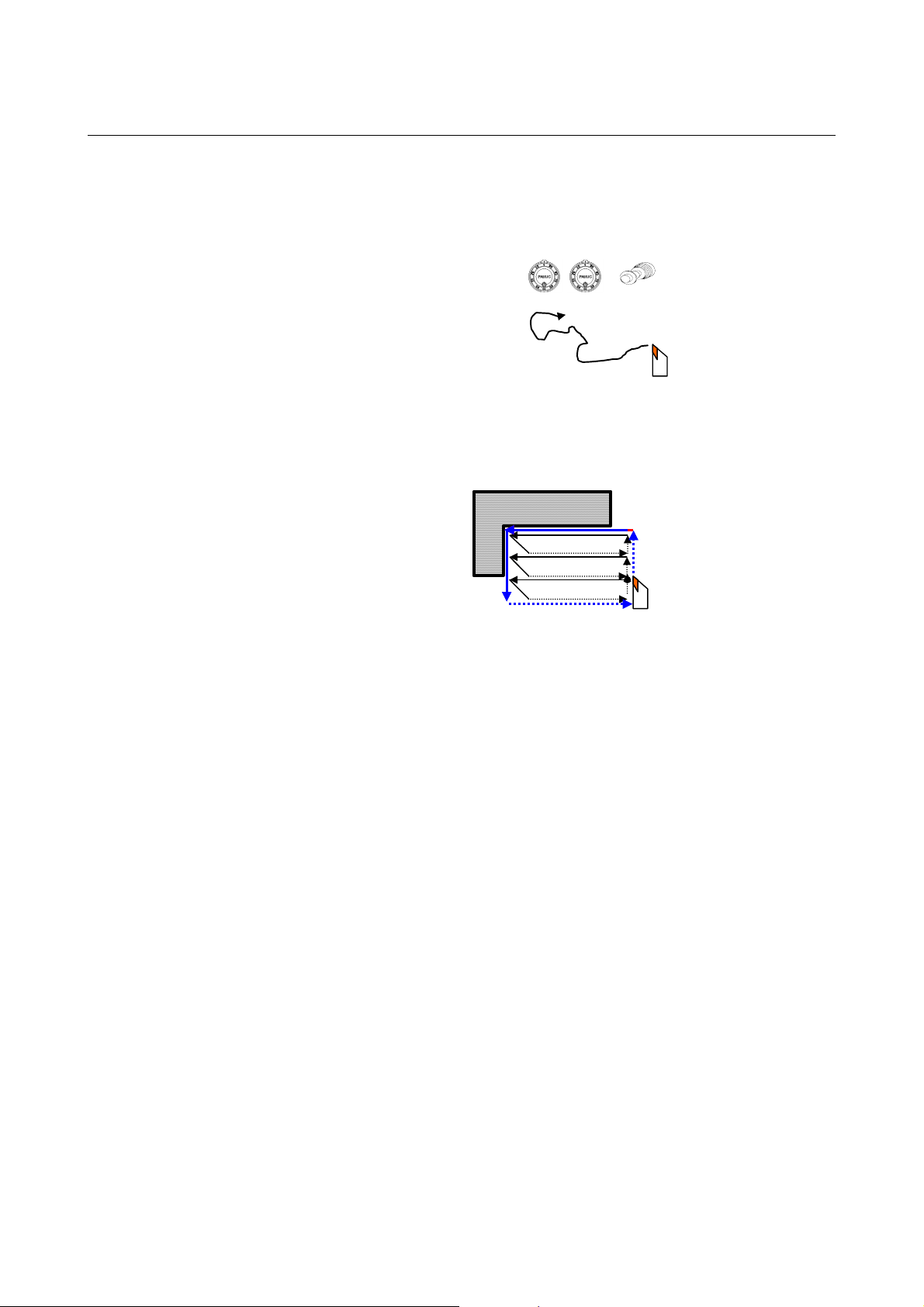
(a) Manual cutting
It is possible to move the tool freely to perform cutting,
using the handle or the JOG switch. It is also possible to
move the tool in a limited area.
(b) Cutting cycles
A cutting cycle is a series of prescribed cutting motions
collected together. By starting the start button, the series
of cutting motions is automatically executed.
Execution
(5) Various cutting cycles containing free figures are available.
It provides all cutting cycles necessary for lathes.
The following cutting cycles are available:
(a) Rough cutting cycle (pattern figure, free figure)
(b) Finish cutting cycle (pattern figure, free figure)
(c) Groove cycle (pattern figure, free figure)
(d) Thread cycle (general-purpose screw)
(e) Re-thread cycle (general-purpose screw)
(f) Hole cycle (drill, tap)
- 4 -
Page 17

II. BASIC SCREEN AND OPERATIONS
Page 18

Page 19
B-64254EN/06 BASIC SCREEN AND OPERATIONS 1.BASE SCREEN
A
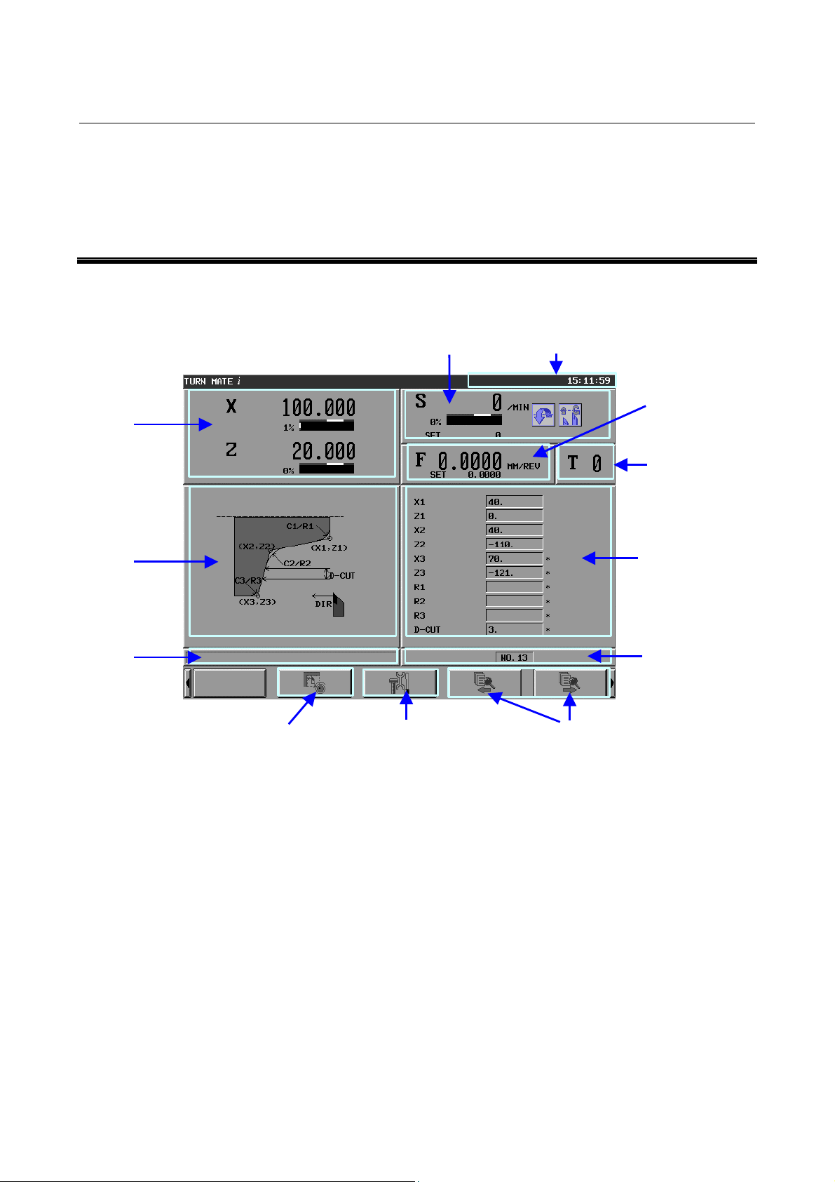
1 BASE SCREEN
TURN MATE i has integrated all information necessary for operation
on a single screen. This integrated screen is called the Base Screen.
(1)
Present
position
(2) Spindle speed
(5) Machine status
(3)
Feedrate
(4)
Tool number
(6)
Guidance
drawing for
cutting cycle
(8)
larm
message
(10) Manual cutting screen
The Base Screen consists of nine sections and four soft keys.
In each section, information display and operation functions are
integrated together. Either by touching a section on the tough panel
or by moving the focus to a section using cursor keys as appropriate
and pressing the [INPUT] key, the operator can jump to the related
operation screen.
(11) Setting screen
Base Screen
(12) Cutting cycle call
(7)
Cutting
cycle data
(9)
Cutting cycle
call number
- 7 -
Page 20

1.BASE SCREEN BASIC SCREEN AND OPERATIONS B-64254EN/06
Each of the sections and soft keys is described below.
(1) Present position section
In this section, the present position (absolute coordinates) and the
load ratio (load meter) of the servo axis are displayed.
Touching this section causes a jump to the workpiece coordinate
system setting screen.
"Workpiece coordinate system setting screen": Screen for
setting the workpiece coordinate system.
(2) Spindle speed section
In this section, the actual spindle rotation speed (rpm (min-1)),
the commanded spindle speed (S_set), and the spindle load ratio
(load meter) are displayed. In addition, the following states are
represented by icons:
(a) Spindle direction (CW or CCW)
(b) Constant surface speed control (enabled or disabled)
Touching this section causes a jump to the spindle speed setting
screen.
"Spindle speed setting screen":
Screen for setting a spindle speed, turning constant surface
speed control ON/FF, and setting a gear number.
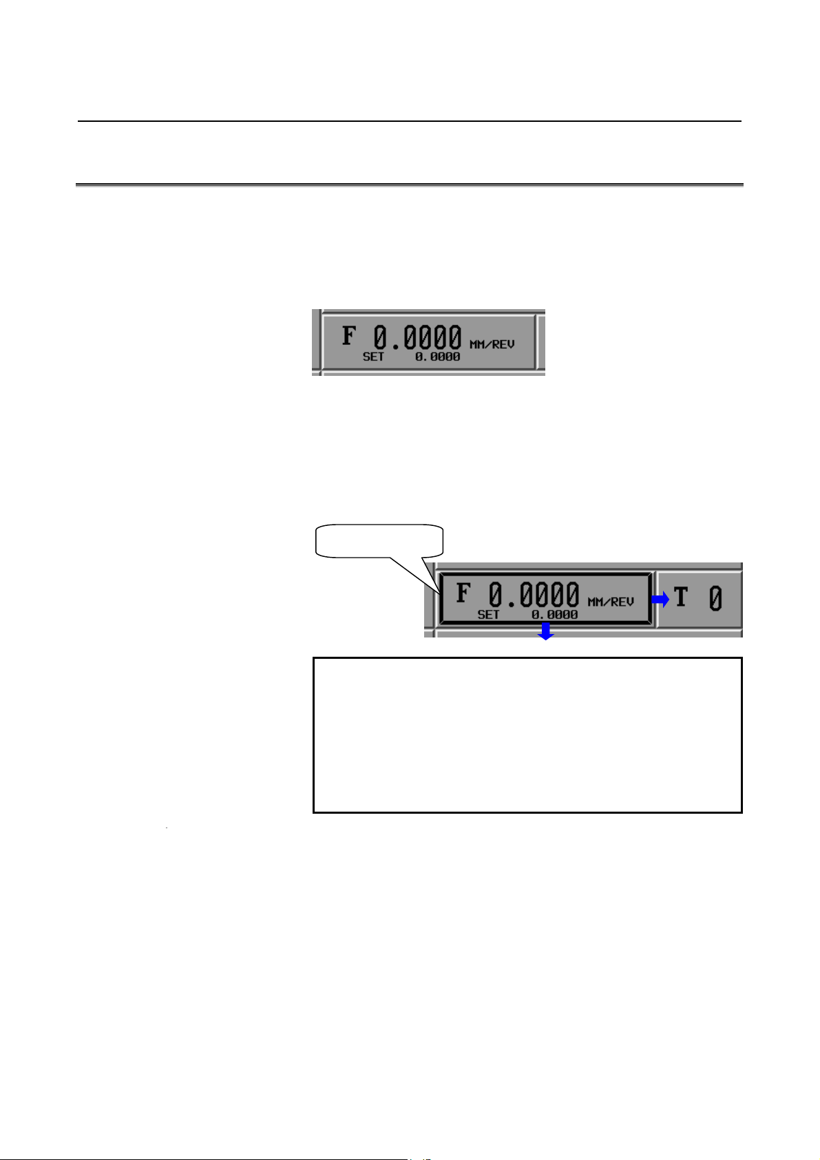
(3) Feedrate section
In this section, the actual feedrate and the commanded feedrate
(F_set) are displayed. Touching this section causes a jump to
the feedrate setting screen.
"Feedrate setting screen":
Screen for setting the feedrate used in a cutting cycle.
(4) Tool number section
In this section, the currently selected tool number is displayed.
Touching this section causes a jump to the tool selection screen.
"Tool selection screen": Screen for selecting the tool to use and
setting tool data (offset value, radius of the tool
nose, and virtual tool tip)
(5) Machine status section
In this section, the machine status is displayed.
MTN : The tool is moving along at least one axis.
(The CNC is in MEM mode.)
ALM : A CNC or machine alarm has been generated.
EMG : Emergency stop state
RESET : Reset state
HOLD : Automatic operation suspend
STOP : Automatic operation stop
FIN : Miscellaneous function under execution
MSG : An operator message has been generated.
- 8 -
Page 21
B-64254EN/06 BASIC SCREEN AND OPERATIONS 1.BASE SCREEN
(6) Guidance drawing for cutting cycle section
In this section, the guidance drawing for the currently selected
cutting cycle is displayed. Touching this section causes a jump
to the cutting cycle selection screen.
"Cutting cycle selection screen":
Screen for selecting the cutting cycle to create.
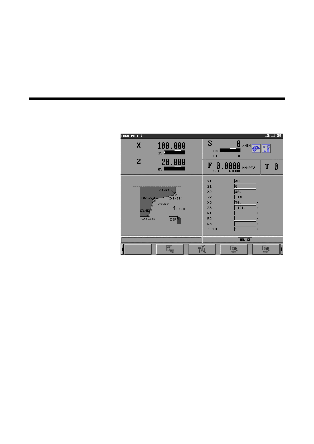
(7) Cutting cycle data section
In this section, the currently selected cutting cycle data (NOTE)
is displayed. Touching this section causes a jump to the cutting
cycle input screen.
"Cutting cycle input screen":
Screen for editing the input data for the currently selected
cutting cycle
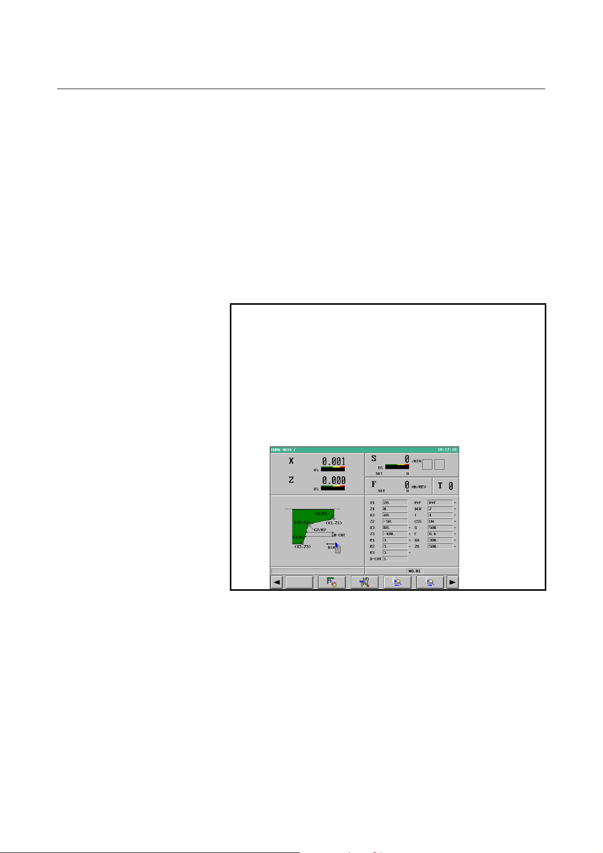
NOTE
By enabling the optional function and parameter
below, it is possible to display cutting methods
(R+F, DIR, and XA/ZA) and cutting conditions (T,
CSS, S, and T) as additional cutting cycle data.
• Optional function: Expansion of Machining
Cycle
• Parameter: Bit 4 (DID) of parameter No. 9103
= 1
Screen example)
(8) Alarm section
In this section, a P/S alarm (38 characters in length) is displayed.
Touching this section causes a jump to the alarm screen.
"Alarm screen":
Screen for displaying all NC alarm messages and operator
messages.
- 9 -
Page 22

1.BASE SCREEN BASIC SCREEN AND OPERATIONS B-64254EN/06
(9) Cutting cycle call number section
TURN MATE i provides 40 areas for storing cutting cycle data.
The serial numbers for these storage areas are used as cutting
cycle call numbers. In this section, the currently selected
cutting cycle call number is displayed. Touching this section
causes a jump to the cutting cycle call selection screen.
"Cutting cycle call selection screen":
Screen for selecting and deleting cutting cycles.
(10) Manual cutting screen switching soft key: [HANDLE]
This soft key causes a switch to the manual cutting screen.
"Manual cutting screen": Screen for performing manual
cutting.
(11) Setting screen switching soft key: [SETTING]
This soft key causes a switch to the setting screen.
"Setting screen":
Screen for selecting a language, switching between inch and
metric systems, and setting a default finishing amount.
(12) Cutting cycle call soft keys: [←][→]
Touching the [←] soft key causes selection of the cutting cycle
call number equal to the currently selected cutting cycle call
number minus 1.
Touching the [→] soft key causes selection of the cutting cycle
call number equal to the currently selected cutting cycle call
number plus 1.
- 10 -
Page 23

2.BASIC SCREEN
B-64254EN/06 BASIC SCREEN AND OPERATIONS
OPERATIONS
2 BASIC SCREEN OPERATIONS
This chapter consists of the sections below.
2.1 BUTTON OPERATION ............................................................12
2.2 CURSOR OPERATION.............................................................13
2.3 TAB OPERATION.....................................................................13
2.4 CALCULATOR OPERATION..................................................14
- 11 -
Page 24
2. BASIC SCREEN
OPERATIONS
BASIC SCREEN AND OPERATIONS B-64254EN/06
2.1 BUTTON OPERATION
A section in which information display and operation functions are
integrated together appear raised as shown below
that does not appear raised provides information display functions
only.)
Such a raised section is called a button.
There are two methods to button operation:
(1) Touch the desired section on the touch panel.
(2) Move the focus (button cursor) to the desired section using the
cursor keys (↑, ↓, ←, and →) as appropriate and press the
[INPUT] key
Either of the above methods causes a jump to the related operation
screen.
Button cursor
(NOTE 2)
.
NOTE
1 To make a button appear more pronouncedly
raised, change the color settings on the color
palette, using parameters Nos. 9156 and 9162.
2 The method of moving the focus to a section using
cursor keys requires the MDI key operation
function (option). For details, see Part IX, "MDI
Key Operation Function".
(NOTE 1)
. (A section
- 12 -
Page 25
2.BASIC SCREEN
B-64254EN/06 BASIC SCREEN AND OPERATIONS
OPERATIONS
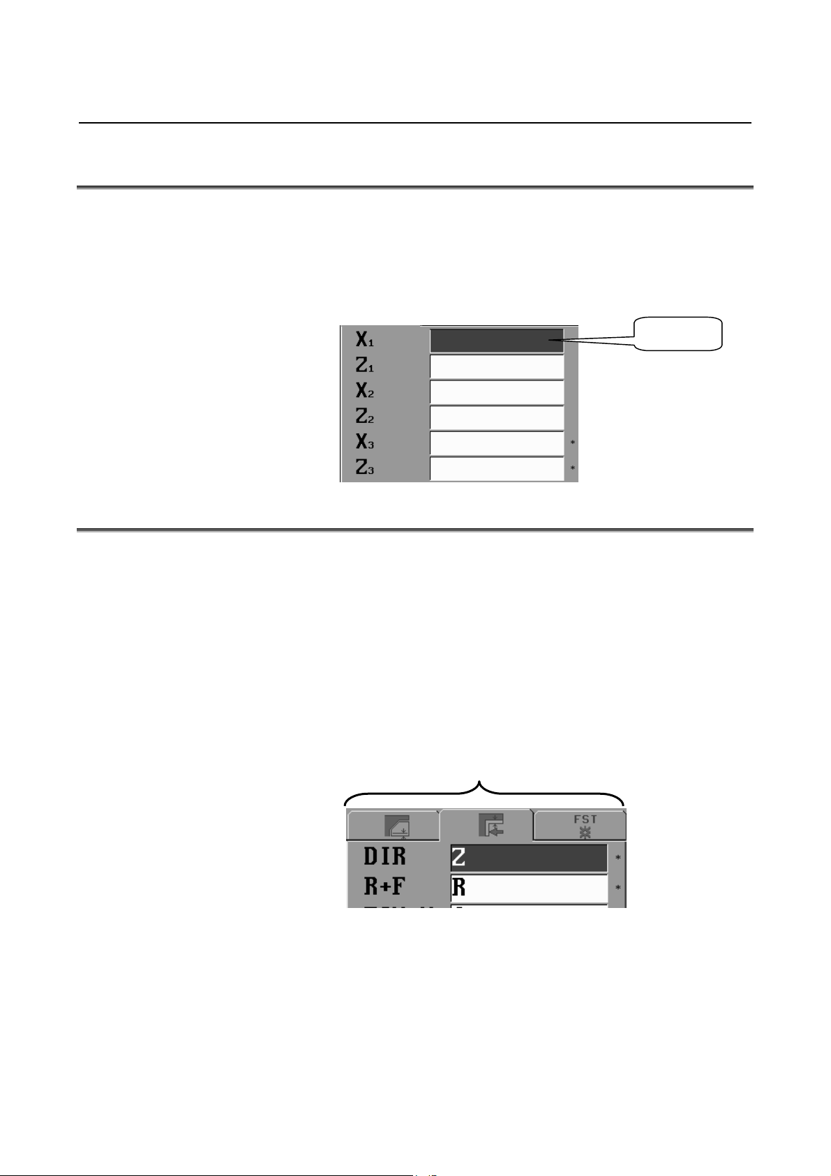
2.2 CURSOR OPERATION
The cursor can be moved between edit boxes, using the cursor key (↑
and ↓). The edit box on which the cursor is positioned is displayed
gray (blue on a color LCD).
By entering data in one edit box, the cursor is automatically moved to
the next edit box.
Cursor
2.3 TAB OPERATION
On a setting screen such as the cutting cycle input screen, multiple
tabs are displayed on top of the data in an edit box.
By selecting one of these tabs, it is possible to switch to the
corresponding one of the multiple edit boxes hidden behind.
There are two methods to tab selection:
(1) Touch a tab on the touch panel.
(2) Press the cursor key (← and →) as appropriate.
Either of the methods above causes the edit box of the selected tab to
appear.
Tabs
- 13 -
Page 26
2. BASIC SCREEN
OPERATIONS
BASIC SCREEN AND OPERATIONS B-64254EN/06
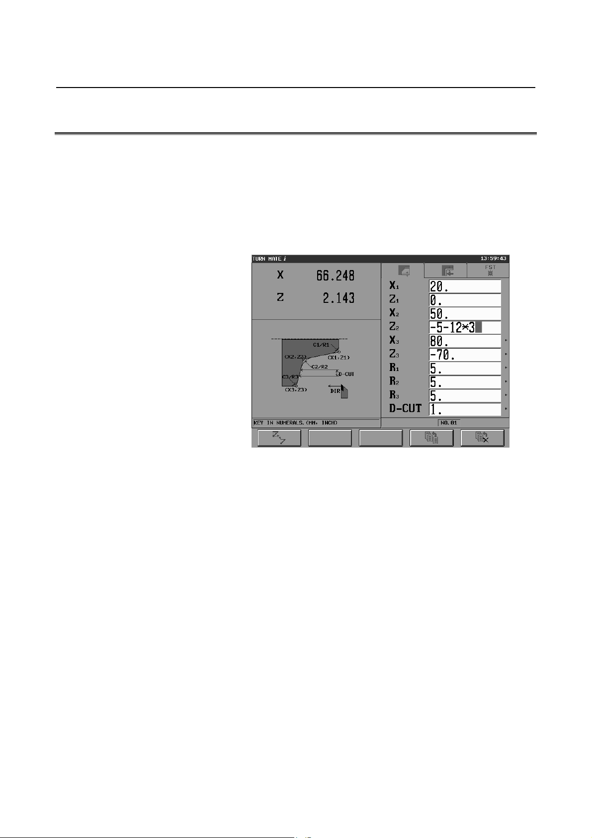
2.4 CALCULATOR OPERATION
Functions are provided whereby when numeric data is input,
expressions for arithmetic operations, trigonometric functions, square
root calculations, and so forth can be input for calculation.
These functions can be used in the input of cycle data, input of free
figure data, and setting of various data (such as workpiece coordinate
system data).
Input example)
Cutting cycle input screen example
The following describes each calculation operation.
• Arithmetic operations
(addition, subtraction, multiplication, and division)
Arithmetic operations are performed by using the key operations
described below. The result of a calculation is displayed at the
cursor position of input data.
(1) Addition : 100.+200. [INPUT]
(2) Subtraction : 100.-200. [INPUT]
(3) Multiplication : 100.*200. [INPUT]
(4) Division : 100./200. [INPUT]
- 14 -
Page 27

2.BASIC SCREEN
B-64254EN/06 BASIC SCREEN AND OPERATIONS
• Trigonometric functions
(sine, cosine, tangent, arcsine, arccosine, arctangent)
Trigonometric function calculations are performed by using the
key operations described below. The result of a calculation is
displayed at the cursor position of input data.
(1) Sine : SIN[45] [INPUT]
(2) Cosine : COS[45] [INPUT]
(3) Tangent : TAN[45] [INPUT]
(4) Arcsine : ASIN[0.5] [INPUT]
(5) Arccosine : ACOS[0.5] [INPUT]
(6) Arctangent : ATAN[20,2] [INPUT]
(Note that for an arctangent calculation, a special format using
two arguments is required. Enter data according to the format
ATAN[a,b]. arctan(a/b) is calculated.)
For a calculation, brackets ( [ ] ) are required at all times.
• Square root
A square root calculation is performed by using the key
operations described below. The result of a calculation is
displayed at the cursor position of input data.
(1) Square root : SQRT[45] [INPUT]
For a calculation, brackets ( [ ] ) are required at all times.
• Exponential functions
Exponential function calculations are performed by using the key
operations described below. The result of a calculation is
displayed at the cursor position of input data.
(1) Exponential function 1 (An exponential function of e =
2.718... can be calculated.) :
EXP[4] [INPUT]
(2) Exponential function 2 ("a" raised to the power of "b" can
be calculated.) :
PWR[4,3] [INPUT]
(Note that for a calculation of exponential function 2, a special
format using two arguments is required. Enter data according to
the format PWR[a,b]. "a" raised to the power of "b" is
calculated.)
For a calculation, brackets ( [ ] ) are required at all times.
• Logarithmic functions
(common logarithm, natural logarithm)
Logarithmic function calculations are performed by using the key
operations described below. The result of a calculation is
displayed at the cursor position of input data.
(1) Common logarithm : LOG[45] [INPUT]
(2) Natural logarithm : LN[45] [INPUT]
For a calculation, brackets ( [ ] ) are required at all times.
OPERATIONS
- 15 -
Page 28

2. BASIC SCREEN
OPERATIONS
BASIC SCREEN AND OPERATIONS B-64254EN/06
• Absolute value
An absolute value calculation is performed by using the key
operations described below. The result of a calculation is
displayed at the cursor position of input data.
(1) Absolute value : ABS[-45] [INPUT]
For a calculation, brackets ( [ ] ) are required at all times.
• Rounding
Rounding operations are performed by using the key operations
described below. The result of a calculation is displayed at the
cursor position of input data.
(1) Rounding 1 (rounding off to an integer) :
RND[1.234] [INPUT]
(2) Rounding 2 (rounding off "a" to the decimal places
RND2[1.267,0.01] [INPUT]
(Note that for a calculation of rounding 2, a special format using
two arguments is required. Enter data according to the format
RND[a,b]. The value of "a" is rounded off to the decimal places
specified by "b". As "b", do not specify a value other than 1,
0.1, 0.01, and so forth.)
For a calculation, brackets ( [ ] ) are required at all times.
• Discarding
This operation discards all decimal places. A discarding
operation is performed by using the key operations described
below. The result of a calculation is displayed at the cursor
position of input data.
(1) Discarding : FIX[1.234] [INPUT]
For a calculation, brackets ( [ ] ) are required at all times.
• Circle ratio
A circle ratio calculation is performed by using the key
operations described below. The circle ratio 3.14... is indicated.
(1) Circle ratio : PAI [INPUT]
specified by "b") :
- 16 -
Page 29
3.SETTING OF
B-64254EN/06 BASIC SCREEN AND OPERATIONS
COORDINATE SYSTEM
3 SETTING OF COORDINATE SYSTEM
TURN MATE i assumes the coordinate system shown below.
It is necessary to set the workpiece coordinate system before operating
the machine.
-X
+Z
-Z
+X
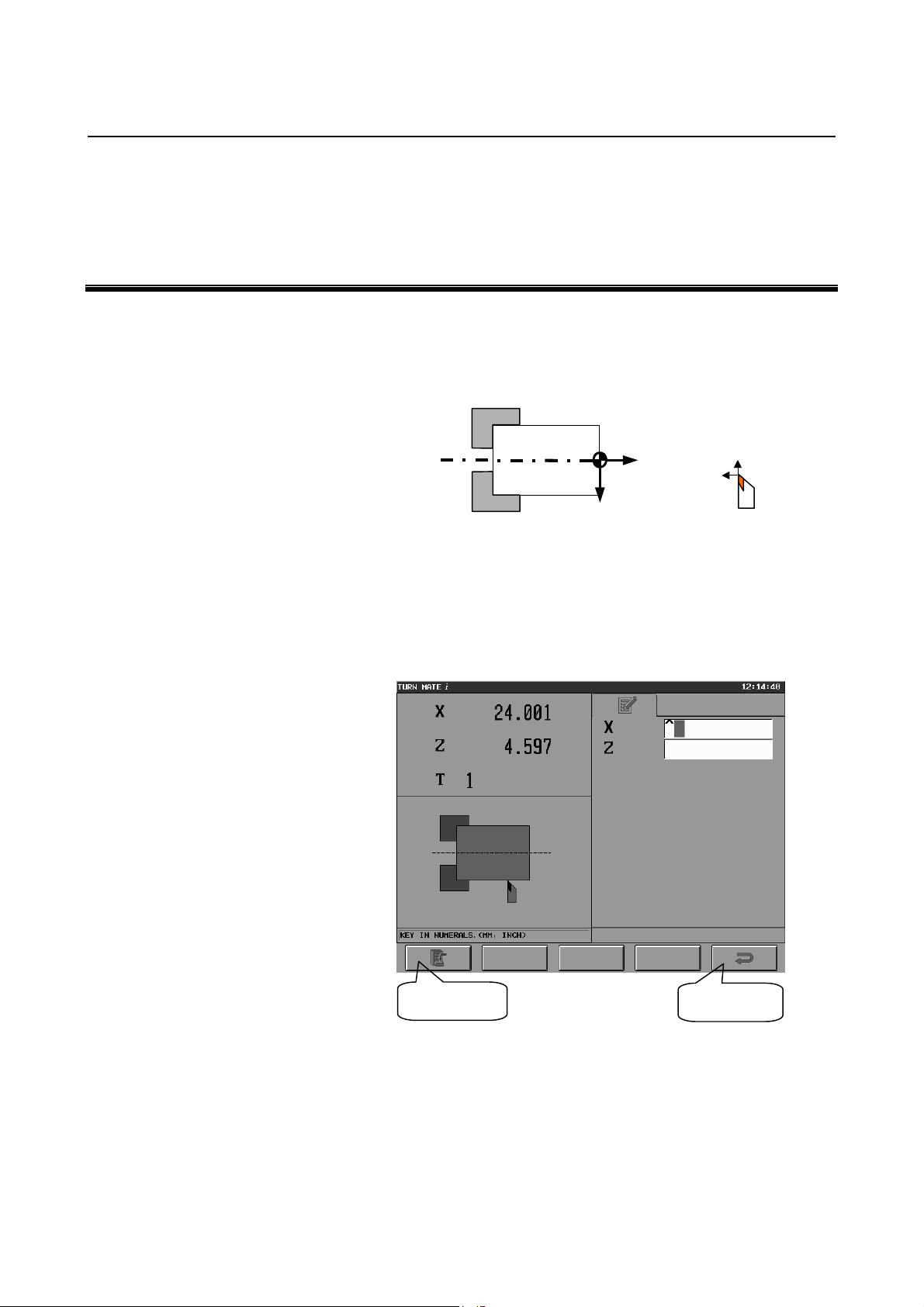
Push the present position screen area on the Base Screen to display the
workpiece coordinate system setting screen, shown below. The
present position and the active tool number are displayed on the upper
left side of the screen. On the right side of the screen, a data input
area is displayed, and on the bottom left side of the screen, the
guidance drawing for input items is displayed.
[SET] key
Workpiece coordinate system setting screen (X coordinate)
[RET] key
- 17 -
Page 30
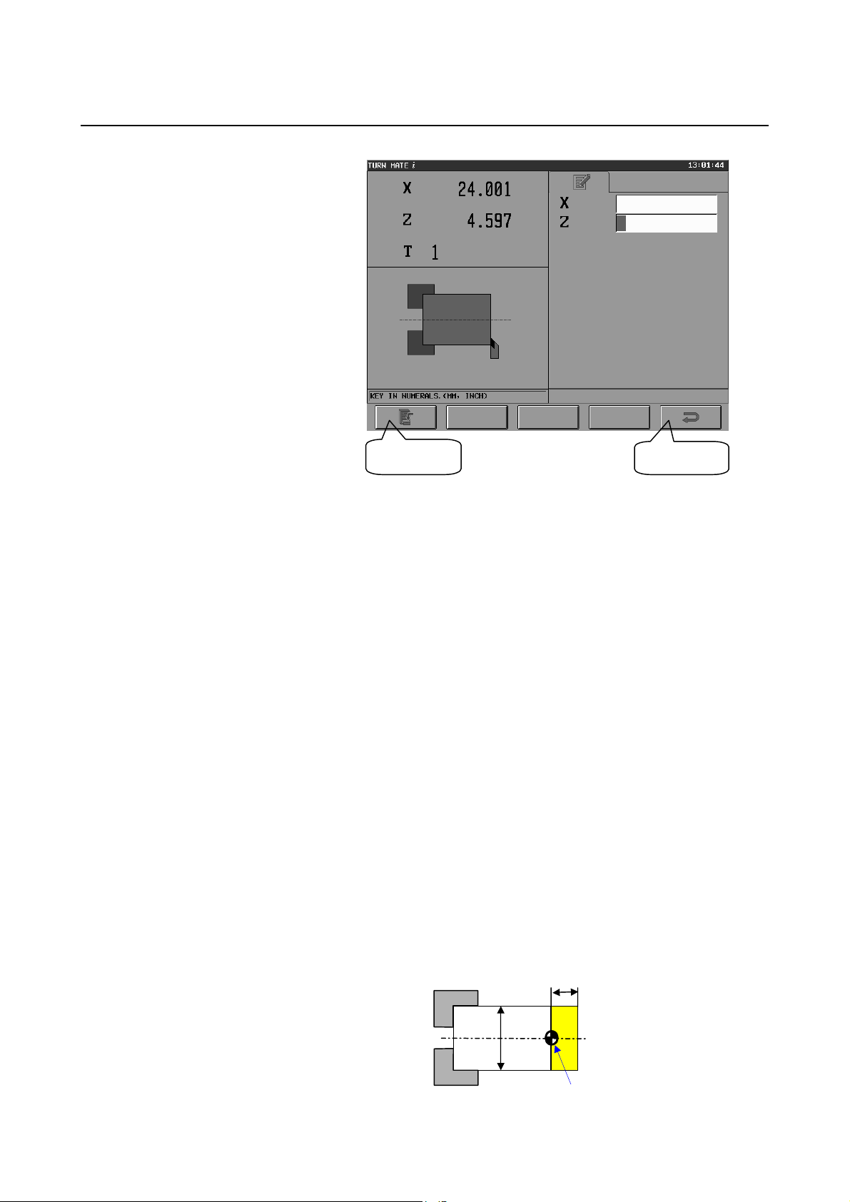
3. SETTING OF
φ
COORDINATE SYSTEM
BASIC SCREEN AND OPERATIONS B-64254EN/06
[SET] key
Workpiece coordinate system setting screen (Z coordinate)
It is possible to decide on the origin of the workpiece coordinate
system by following the procedure described below.
<Measurement of X coordinate>
(1) To determine a standard plane, cut the side at a low feedrate,
using the handle.
(2) Retract the tool along the Z-axis only, not moving it along the
X-axis, then stop the spindle.
(3) Measure the diameter of the workpiece, assume this value as the
input value for X, and set it for the input item X.
(4) Push the [SET] key.
(5) The X coordinate of the present position shown on the upper left
side of the screen is replaced with the value entered in <3>.
<Measurement of Z coordinate>
(1) Bring the tool in contact with the workpiece face side, and
measure the Z coordinate.
(2) Set the desired value for the input item Z.
(3) Push the [SET] key.
(4) The Z coordinate of the present position shown on the upper left
side of the screen is replaced with the value entered in <2>.
Example)
If deciding on the origin of the workpiece coordinate system as
shown in the figure below
[RET] key
10
40
Workpiece origin
- 18 -
Page 31
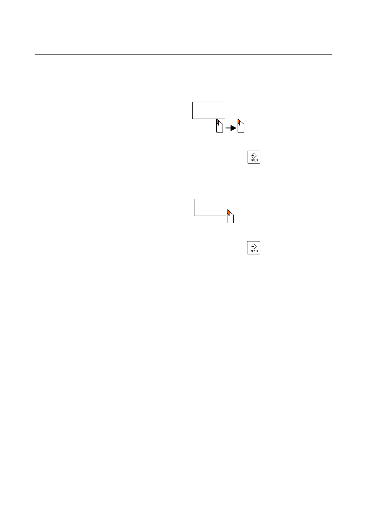
3.SETTING OF
B-64254EN/06 BASIC SCREEN AND OPERATIONS
(1) First cut the side and then retract the tool along the Z-axis.
Stop the spindle and measure the diameter of the workpiece.
(2) Enter the measured value (40.0) in the X coordinate data
COORDINATE SYSTEM
area, and push the [INPUT] (
) key.
(3) Push the [SET] key. (The X coordinate of the present
position is replaced with 40.0.)
(4) Bring the tool in contact with the workpiece side face.
(5) Enter the measured value (10.0) in the Z coordinate data
area, and push the [INPUT] (
) key.
(6) Push the [SET] key. (The Z coordinate of the present
position is replaced with 10.0.)
- 19 -
Page 32

4. SETTING OF SPINDLE
INFORMATION
BASIC SCREEN AND OPERATIONS B-64254EN/06
4 SETTING OF SPINDLE INFORMATION
It is necessary to set a spindle speed before operating the machine.
Pushing the spindle speed screen area on the Base Screen causes the
spindle speed setting screen to be displayed.
There are three operations related to the spindle:
(1) Setting a spindle speed (/MIN).
(2) Setting a surface speed (M/MIN or FEET/MIN) and a maximum
spindle speed (/MIN).
(3) Setting a gear number.
Each operation is described below.
(Switch to the screen for each operation, with an appropriate tab
operation.)
NOTE
If specifying a spindle speed on each cutting cycle
input screen, these operations are not required.
- 20 -
Page 33
4.SETTING OF SPINDLE
B-64254EN/06 BASIC SCREEN AND OPERATIONS
INFORMATION
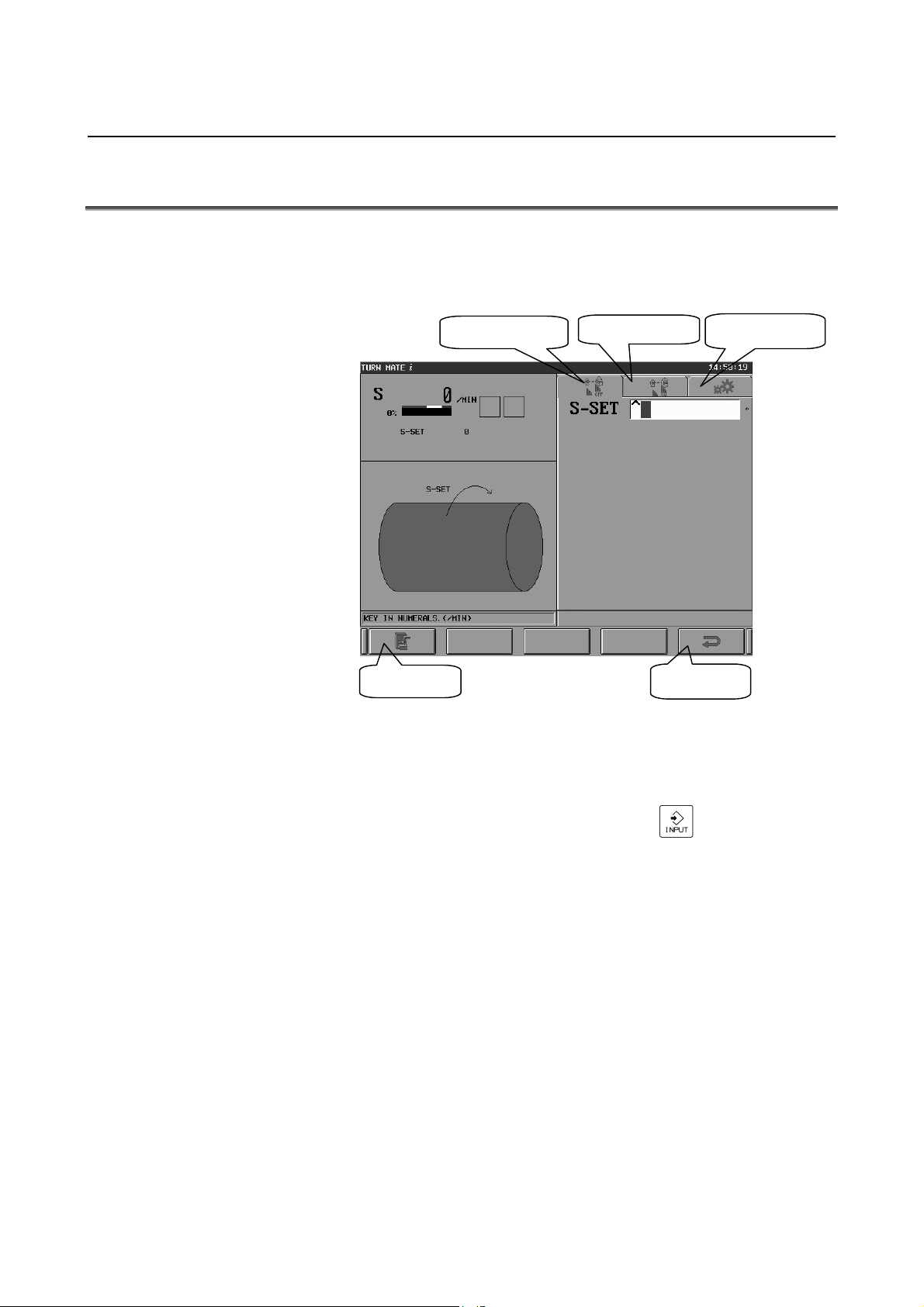
4.1 SETTING OF SPINDLE SPEED
Selecting the tab [CSS OFF] causes the screen shown below to appear.
This screen is used to set a spindle speed (RPM(MIN
constant surface speed control.
Tab [CSS OFF]
Tab [CSS ON]
-1
)) and disable
Tab [G-NO]
[SET] key
Spindle speed setting screen (tab [CSS OFF])
[RET] key
The procedure is as described below.
(1) In the S-SET data area, enter the desired spindle speed
-1
(RPM(MIN
)), and push the [INPUT] ( ) key.
(The message “KEY IN NUMERALS. (/MIN)” is displayed in
the message space on the bottom left side of the screen).
(2) Push the [SET] key.
Pushing the [SET] key disables constant surface speed control,
enabling the input spindle speed. (In the S area, the actual spindle
speed in the CNC is displayed.)
- 21 -
Page 34

4. SETTING OF SPINDLE
INFORMATION
BASIC SCREEN AND OPERATIONS B-64254EN/06
4.2 SETTING OF SURFACE SPEED
Selecting the tab [CSS ON] causes the screen below to appear. This
screen is used to set a surface speed (m/min) and enable constant
surface speed control.
Spindle speed setting screen (tab [CSS ON])
The procedure is as described below.
(1) In the S-CSS data area, enter the desired surface speed (m/min),
Tab [CSS ON]
and push the [INPUT] (
) key. (The message "KEY IN
NUMERALS. M/MIN, FEET/MIN)" is displayed in the
message space on the bottom left side of the screen.)
(2) In the S-MAX data area, enter a maximum spindle speed
(RPM(MIN
-1
)), and push the [INPUT] ( ) key.
(The message "KEY IN NUMERALS. M/MIN, FEET/MIN)"
is displayed in the message space on the bottom left side of the
screen.)
(3) Push the [SET] key.
Pushing the [SET] key enables constant surface speed control,
enabling the input surface speed and maximum spindle speed. (In the
S area, the actual spindle speed in the CNC is displayed.)
NOTE
Change the surface speed unit to (feet/min), using
inch/metric switching.
- 22 -
Page 35
4.SETTING OF SPINDLE
B-64254EN/06 BASIC SCREEN AND OPERATIONS
INFORMATION
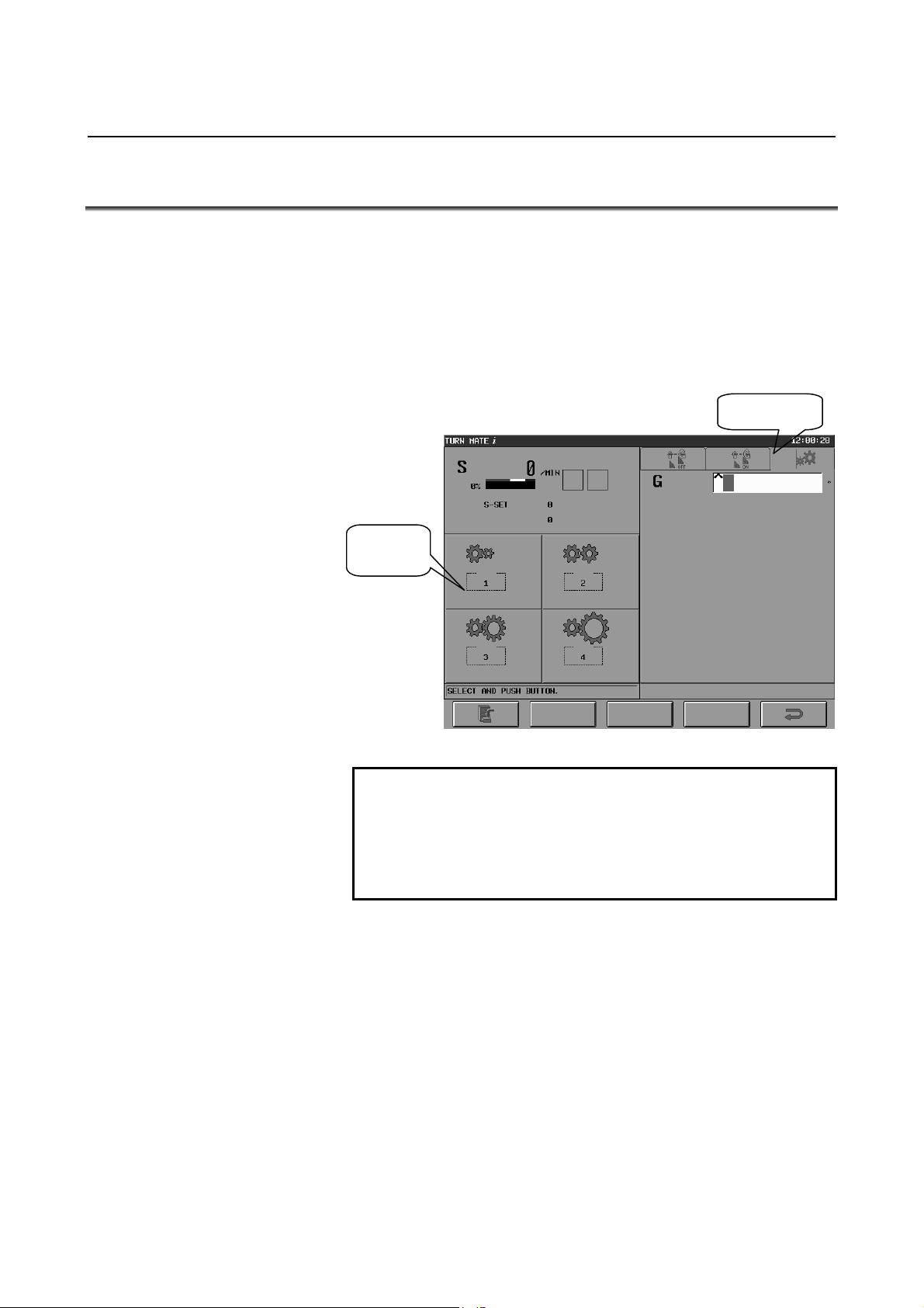
4.3 SETTING OF GEAR NUMBER
Selecting the tab [G-NO] causes the screen shown below to appear.
This screen is used to specify a gear number (1 to 4).
Buttons are displayed on the bottom left side of the screen, and by
pushing a button (or selecting it with the button cursor), the
corresponding gear number is set.
Alternatively, a number can be set by entering it from the MDI
keyboard.
Tab [G-NO]
Push one
of them.
Spindle speed setting screen (tab [G-NO])
NOTE
1 Switch between display and non-display, using bit
6 of parameter No. 9102.
2 When setting a gear number, be sure to set
parameters Nos. 9115 to 9118 (M code to select a
gear number).
- 23 -
Page 36

4. SETTING OF SPINDLE
INFORMATION
BASIC SCREEN AND OPERATIONS B-64254EN/06
4.4 SETTING OF SPINDLE SPEED USING BUTTON ON
MACHINE OPERATOR'S PANEL
By setting bit 5 of parameter No. 9103 to 1, it is possible to specify
the value specified on the spindle speed setting screen to the CNC
when pushing the spindle rotation button on the machine operator's
panel. The procedure is as described below.
(1) On the spindle setting screen, enter a value and push the [SET]
key, and the entered value will be stored in memory. This value
will be retained even after the power is turned OFF. (At this
point, the value is not specified to the CNC.)
(2) Upon pushing the spindle rotation button on the machine
operator's panel, the value retained in (1) is specified to the CNC.
NOTE
This feature requires that the ladder program be
modified. For details, see A.5, "SPINDLE
SPEED", in the Appendix (for machine tool
builders).
- 24 -
Page 37

5.SETTING OF TOOL
B-64254EN/06 BASIC SCREEN AND OPERATIONS
INFORMATION
5 SETTING OF TOOL INFORMATION
Pushing the tool number display area on the Base Screen causes the
tool selection screen to appear. On the upper side of the screen, the
currently selected tool number and tool offset data are displayed.
- 25 -
Page 38

5. SETTING OF TOOL
INFORMATION
BASIC SCREEN AND OPERATIONS B-64254EN/06
5.1 TOOL SELECTION
To enable tool offset, first push the button for the tool number to use
and then push the [SET] key at the bottom of the screen.
To set tool offset data, first push the button for the tool for which to
set tool offset data and then push the [EDIT] key at the bottom of the
screen to display the tool offset setting screen. On this screen, set
and change tool offset data.
To disable tool offset, push the [CAN] key at the bottom of the screen.
This causes 0 to be displayed at the tool number on the upper side of
the screen, disabling tool offset. To return to the Base Screen, push
the [RET] key at the bottom of the screen.
Pushing the [EDIT] key causes the tool offset setting screen for setting
tool offset values to appear.
Cursor for selection
[SET] key [EDIT] key [CAN] key
Tool selection screen
NOTE
1 Up to 16 tools can be registered.
2 If the [SET] key is pushed, tool offset is
compensated for differently depending on the
setting of NC parameter No. 5002.
3 On this screen, tool-nose radius compensation
cannot be applied.
4 This screen can be switched between display and
non-display, using bit 7 of parameter No. 9102.
[RET] key
- 26 -
Page 39
5.SETTING OF TOOL
B-64254EN/06 BASIC SCREEN AND OPERATIONS
INFORMATION
5.2 INPUT OF TOOL OFFSET
Pushing the [EDIT] key on the tool selection screen causes the tool
offset setting screen to appear.
There are three tool offset setting operations:
(1) Direct input of tool offset (absolute command).
(2) Direct input of tool offset (incremental command).
(3) Measurement and input of tool offset.
Each operation is described below.
(Switch to the screen for each operation, with an appropriate tab
operation.)
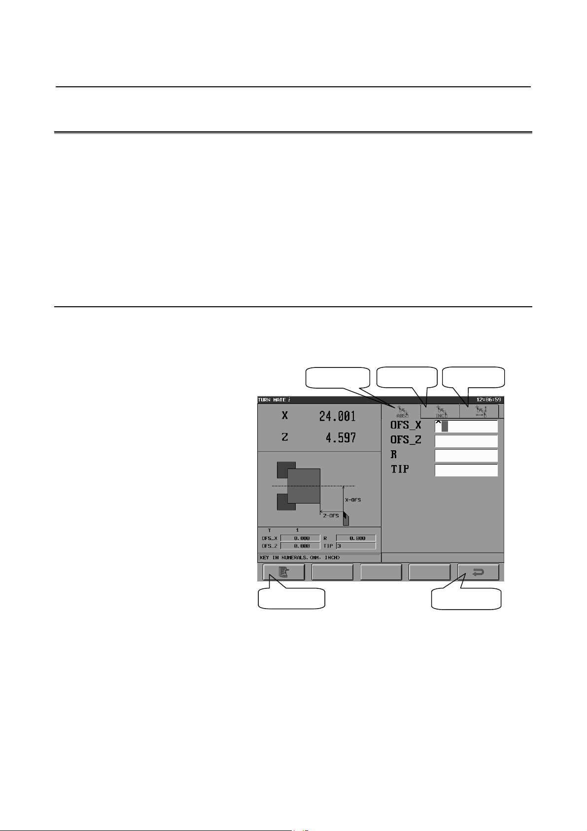
5.2.1 Direct Input of Tool Offset
On this screen, the tabs [ABS] and [INC] enable direct input and
editing of tool offset (radius of the tool nose, virtual tool tip, and
offset).
Tab [ABS]
[SET] key
Tool offset setting screen (tab [ABS])
Tab [INC]
Tab [MES]
[RET] key
- 27 -
Page 40
5. SETTING OF TOOL
INFORMATION
BASIC SCREEN AND OPERATIONS B-64254EN/06
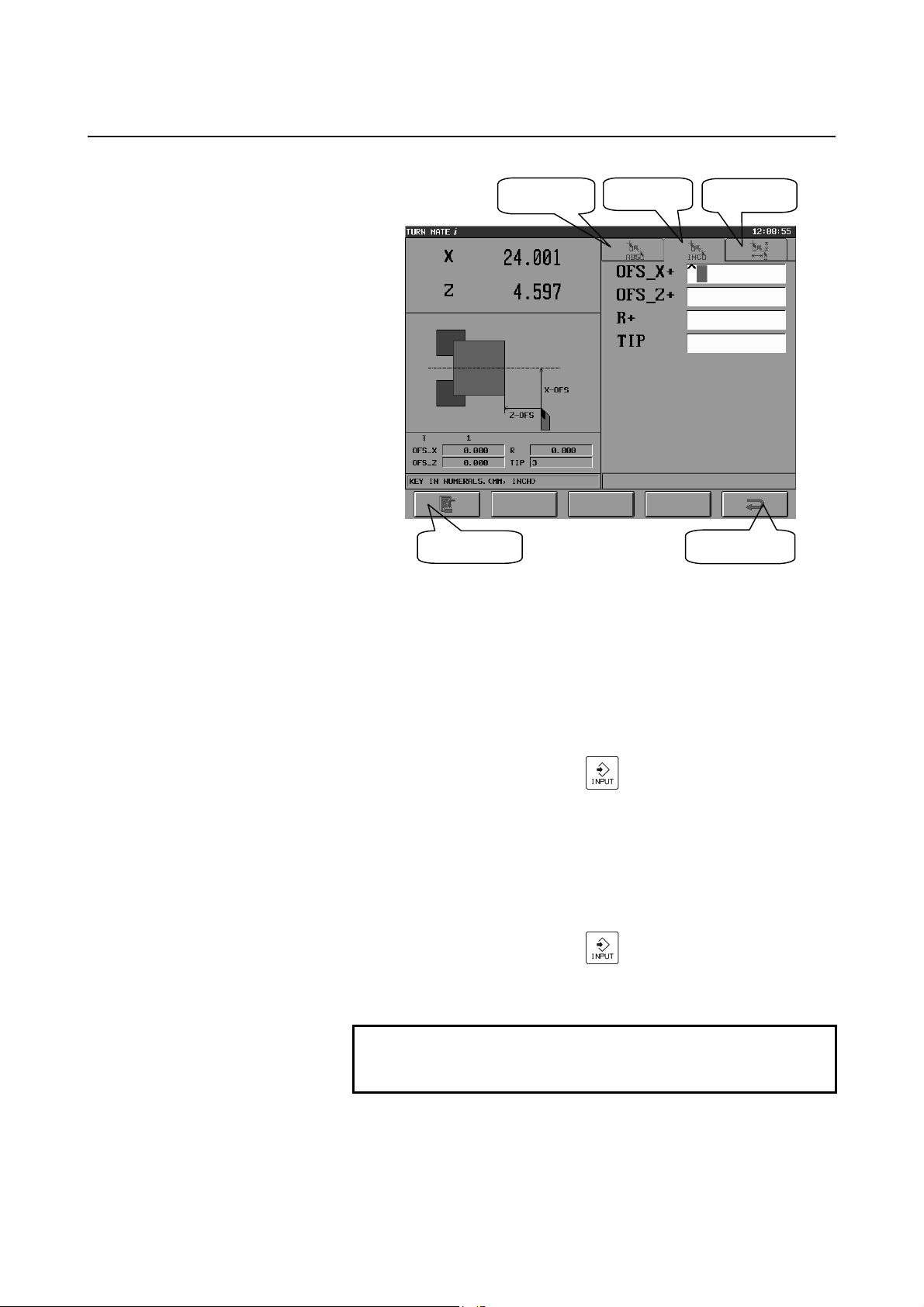
Tab [ABS]
[SET] key
Tool offset setting screen (tab [INC])
The procedure is as described below.
<Setting offset values>
• For input with an absolute command
(1) To enter tool offset data with an absolute command, select
the tab [ABS].
(2) In the OFS_X and OFS_Z data areas, enter offset values,
Tab [INC]
Tab [MES]
[RET] key
and push the [INPUT] (
) key.
(3) Finally, push the [SET] key, and the values will be reflected
in the offset values.
• For input with an incremental command
(1) To enter tool offset data with an incremental command,
select the tab [INC].
(2) In the OFS_X+ and OFS_Z+ data areas, enter offset values,
and push the [INPUT] (
) key.
(3) Finally, push the [SET] key, and the values will be reflected
in the offset values.
NOTE
Offset values are reflected in tool geometry
compensation values.
- 28 -
Page 41
5.SETTING OF TOOL
B-64254EN/06 BASIC SCREEN AND OPERATIONS
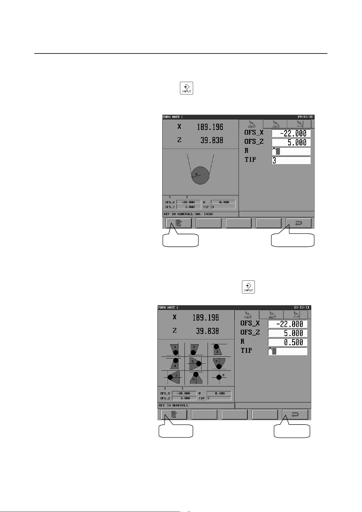
<Setting the radius of the tool nose>
In the R data area, enter the desired radius value, and push the
INFORMATION
[INPUT] (
) key.
Finally, push the [SET] key, and the value is reflected in the
offset values.
[SET] key
Tool offset setting screen (itme "R")
[RET] key
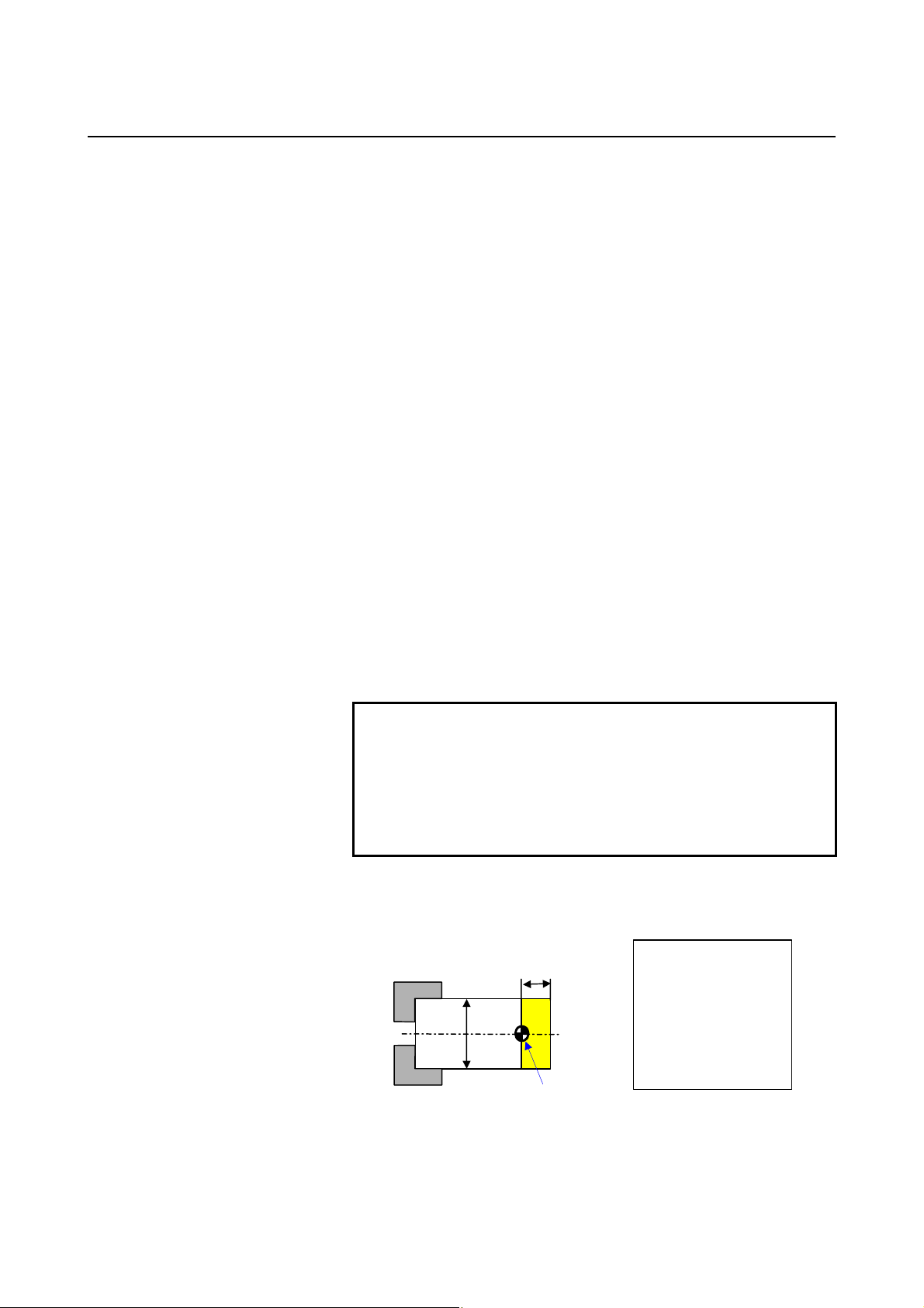
<Setting a virtual toop tip position>
In the TIP data area, enter the desired virtual toop tip position (1
to 9), and push the [INPUT] (
) key. Finally, push the
[SET] key, and the position will be reflected in the offset values.
[SET] key
Tool offset setting screen (item "TIP")
[RET] key
- 29 -
Page 42

5. SETTING OF TOOL
INFORMATION
BASIC SCREEN AND OPERATIONS B-64254EN/06
5.2.2 Measurement of Tool Offset
On this screen, the tab [MES] enables the tool offset values, X and Z
coordinates, to be measured with the procedure described below.
[SET] key
Tool offset setting screen (X coordinate in the tab [MES])
[SET] key
Tool offset setting screen (Z coordinate in the tab [MES])
Tab [MES]
[RET] key
[RET] key
- 30 -
Page 43
5.SETTING OF TOOL
φ
B-64254EN/06 BASIC SCREEN AND OPERATIONS
The tool offset values, X and Z coordinates, can be measured with the
procedure described below.
<Measuring the X coordinate>
(1) Bring the tool in contact with the workpiece side face.
(2) Measure the diameter of the workpiece, and set this value for the
input item X.
(3) Push the [SET] key.
(4) The X coordinate of tool offset on the bottom left side of the
screen will be updated with the value calculated as described
below.
(Present value of the X coordinate in the absolute coordinate
system) - (Value entered in (2))
+ (Present offset value) = (Calculated value)
<Measuring the Z coordinate>
(1) Bring the tool in contact with the workpiece side face and
measure the Z coordinate.
(2) Set the measured value for the input item Z.
(3) Push the [SET] key.
(4) The Z coordinate of tool offset on the bottom left side of the
screen will be updated with the value calculated as described
below.
(Present value of the Z coordinate in the absolute coordinate
system) - (Value entered in (2))
+ (Present offset value) = (Calculated value)
INFORMATION
NOTE
If any of the offset values, the radius of the tool
nose, and the virtual toop tip position of the
currently selected tool is changed on the tool offset
setting screen, the tool is automatically re-selected.
The operator need not, therefore, select the tool
again after editing tool data.
Example)
If setting tool offset as shown in the figure below
10
40
Workpiece origin
Present values :
X=45.0
Z=15.0
Offset values :
X=30.0
Z=5.0
- 31 -
Page 44

5. SETTING OF TOOL
INFORMATION
BASIC SCREEN AND OPERATIONS B-64254EN/06
(1) Bring the tool in contact with the workpiece side face, and
measure the diameter of the workpiece.
(2) Enter the measured value (40.0) in the X coordinate data
area, and push the [INPUT] (
) key.
(3) Push the [SET] key.
Result: (Present value X 45.0) - (Entered value X 40.0) +
(Offset value X 30.0)
= (Calculated value X 35.0)
(4) Then, bring the tool in contact with the workpiece side face.
(5) Enter the measured value (10.0) in the Z coordinate data
area, and push the [INPUT] (
) key.
Result: (Present value Z 15.0) - (Entered value Z 10.0) +
(Offset value X 5.0)
= (Calculated value Z 10.0)
(6) Push the [SET] key.
- 32 -
Page 45

B-64254EN/06 BASIC SCREEN AND OPERATIONS 6.ALARM CHECK
]
6 ALARM CHECK
On the Base Screen, pushing the alarm display area causes the alarm
screen to appear.
Tab [ALARM]
Selecting the tab [ALARM] causes P/S alarms and external alarm
messages to be displayed on the screen.
Selecting the tab [MSG] causes operator messages to be displayed on
the screen.
Alarm screen
Tab [MSG
[RET] key
- 33 -
Page 46

Page 47

III. MANUAL CUTTING
Page 48

Page 49

B-64254EN/06 MANUAL CUTTING 1.MANUAL CUTTING
1 MANUAL CUTTING
It is possible to move the tool freely to perform cutting, using the
handle or the JOG switch.
The operation procedure is as described below.
Set the workpiece coordinate
system
Set a spindle speed
Select a tool
(Set an offset value)
Switch to the manual cutting
screen
Set a JOG feedrate (NOTE)
Operate with handle/JOG
switch
NOTE
1 By setting bits 2 and 1 of parameter No. 9103 to 1,
it is possible to set a JOG feedrate.
2 For cutting with the handle, it is not necessary to
set a JOG feedrate.
- 37 -
Page 50
1.MANUAL CUTTING MANUAL CUTTING B-64254EN/06
Each operation is described below.
(1) Set the workpiece coordinate system
For details, see Chapter 3, "SETTING OF COORDINATE
SYSTEM", in Part II.
(2) Set a spindle speed
For details, see Chapter 4, "SETTING OF SPINDLE
INFORMATION", in Part II.
(3) Set a tool
Set a tool if required.
For details, see Chapter 5, "SETTING OF TOOL
INFORMATION", in Part II.
(4) Switch to the manual cutting screen
On the Base Screen, push the soft key [HANDLE] to switch to
the manual cutting screen, shown below.
[RET] key
Manual cutting screen
- 38 -
Page 51

B-64254EN/06 MANUAL CUTTING 1.MANUAL CUTTING
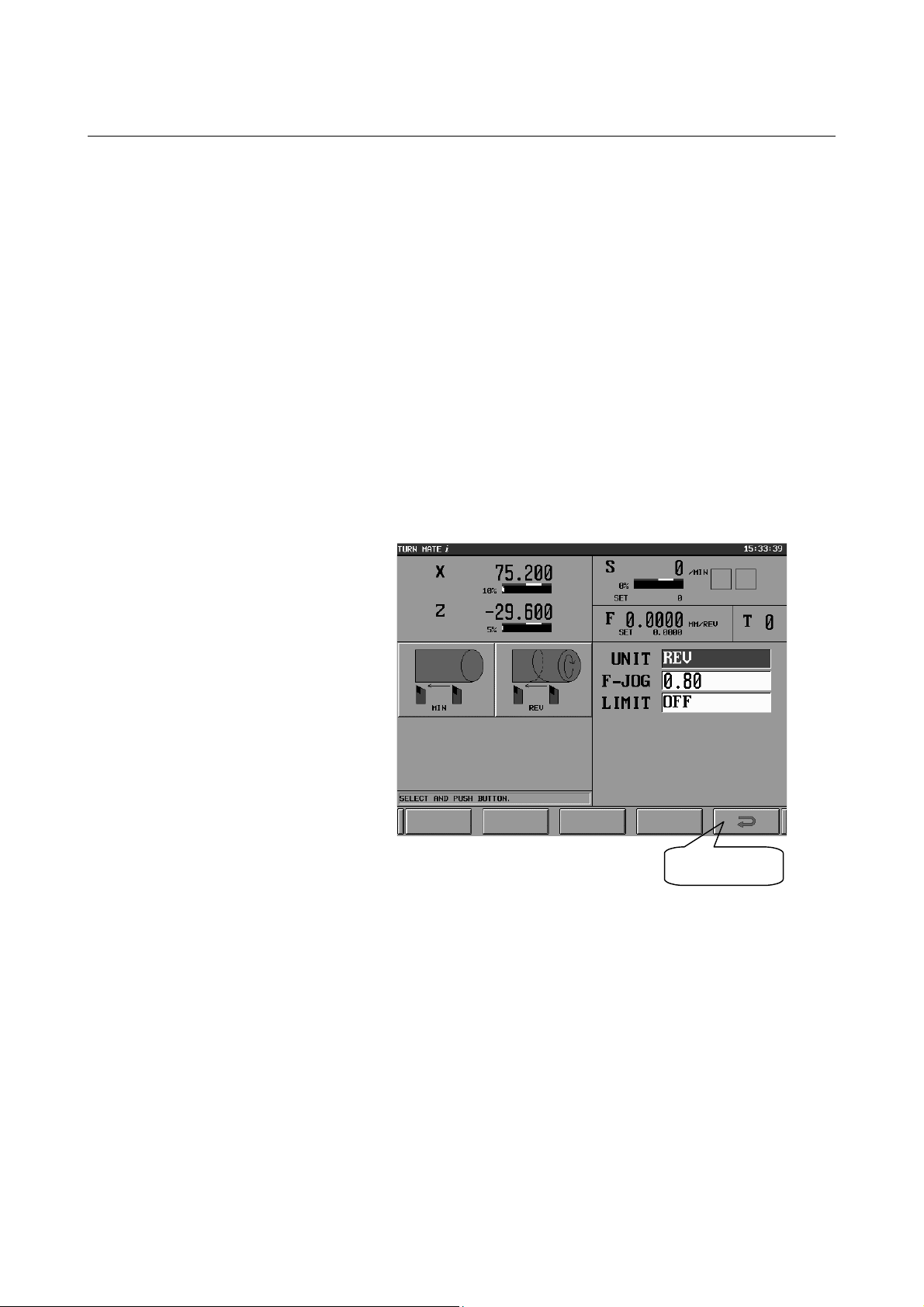
(5) Set a JOG feedrate
On the manual cutting screen, perform the following operation to
set a JOG feedrate:
(1) Move the cursor to the input item "UNIT", and the buttons
[MIN (feed per minute)] and [REV (feed per revolution)]
will be displayed and JOG feed mode will become
selectable.
(2) If selecting [MIN (feed per minute)], enter the desired JOG
feedrate (mm/min or inch/min) in the "F-JOG" data area,
and push the [INPUT] (
be effective.
(3) Similarly, if selecting [REV (feed per revolution)], enter the
desired JOG feedrate (mm/rev or inch/rev) in the "F-JOG"
data area, and push the [INPUT] (
data will be effective.
Note that the data last entered is effective. If it is to be used, it
need not be set again.
) key. The entered data will
) key. The entered
CAUTION
To set a JOG feedrate, bit 4 of JOG feedrate
parameter No. 1402 and parameter No. 1423 are
used. Thus, any previously specified value will be
invalid on this screen. Screens other than this
screen return to the original value, so that the
existing JOG feedrate can be used.
(6) Cutting with the handle/JOG switch
On the manual cutting screen, move the tool to perform cutting,
using the handle or the JOG switch.
- 39 -
Page 52

2. MANUAL CUTTING IN A
LIMITED AREA
MANUAL CUTTING B-64254EN/06
2 MANUAL CUTTING IN LIMITED AREA
It is possible to move the tool in a limited area, using the handle or the
JOG switch.
Prohibited area
Z
The operation procedure is as described below.
Set the workpiece coordinate
system
Setting a spindle speed
Switch to the manual cutting
screen
Set a JOG feedrate (NOTE)
Set a limit area
X
(Set an offset value)
Select a tool
Operate with the handle/JOG
switch
NOTE
1 By setting bits 2 and 1 of parameter No. 9103 to 1,
it is possible to set a JOG feedrate.
2 For cutting with the handle, it is not necessary to
set a JOG feedrate.
- 40 -
Page 53

2.MANUAL CUTTING IN
A
A
B-64254EN/06 MANUAL CUTTING
Each operation is described below.
(1) Set the workpiece coordinate system
For details, see Chapter 3, "SETTING OF COORDINATE
SYSTEM", in Part II.
(2) Set a spindle speed
For details, see Chapter 4, "SETTING OF SPINDLE
INFORMATION", in Part II.
(3) Set a tool
Set a tool if required.
For details, see Chapter 5, "SETTING OF TOOL
INFORMATION", in Part II.
(4) Switch to the manual cutting screen
On the Base Screen, push the soft key [HANDLE] to switch to
the manual cutting screen, shown below.
(5) Set a JOG feedrate
Same as "Set a JOG feedrate" in the preceding chapter, Chapter 1,
"MANUAL CUTTING".
(6) Set a limit area
On the manual cutting screen, a tool movement range (rectangle)
can be set using the handle or the JOG switch. Depending on
the settings of bits 2 and 1 of parameter No. 9103, either of the
two operation procedures on the subsequent pages is possible.
LIMITED ARE
- 41 -
Page 54

2. MANUAL CUTTING IN A
LIMITED AREA
MANUAL CUTTING B-64254EN/06
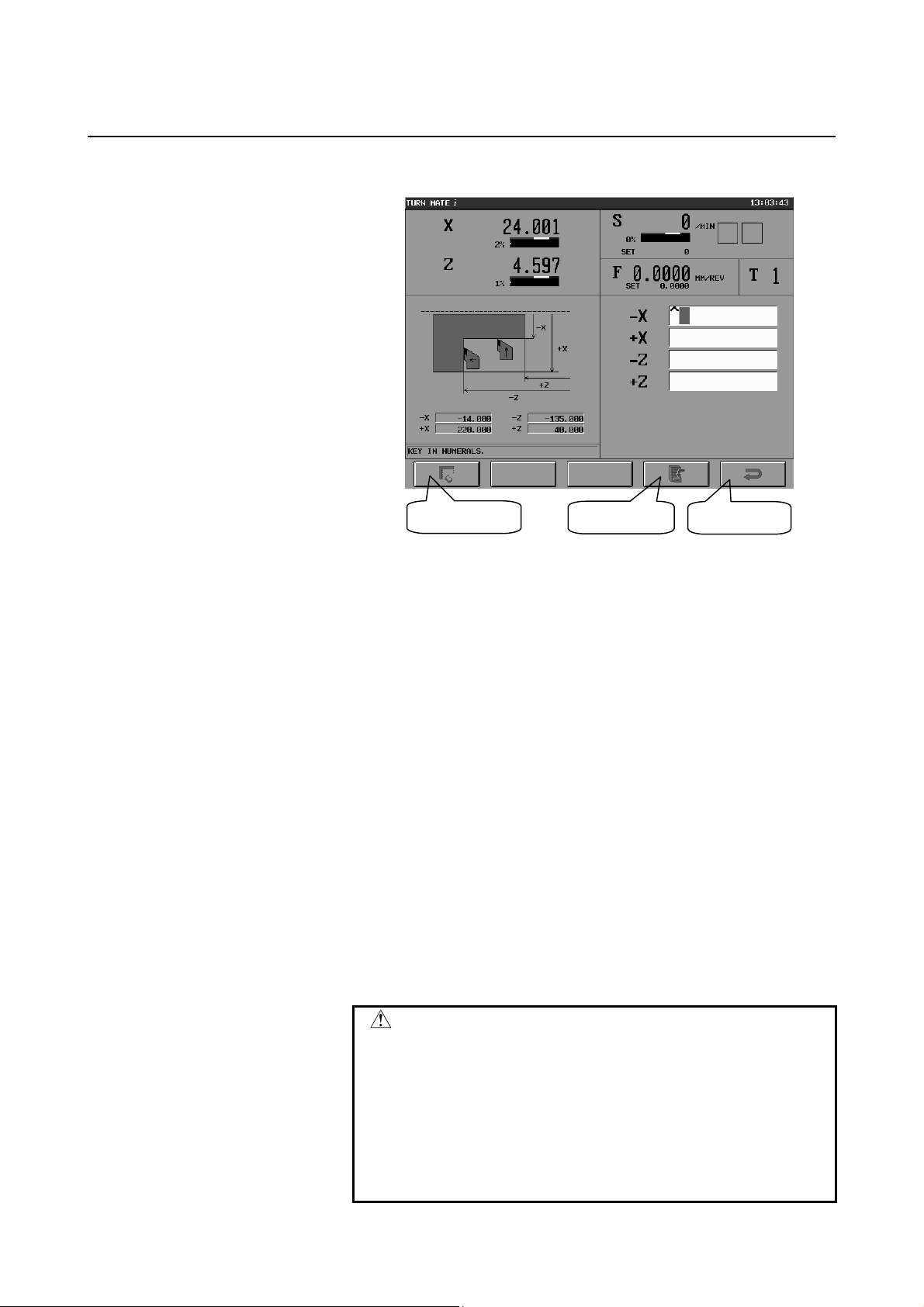
<If bits 2 and 1 of parameter No. 9103 are 1>
Manual cutting screen (1)
It is possible to set a tool movement range with the procedure below.
(1) Move the cursor to the input item "LIMT", and the buttons [ON
(enable)] and [OFF (disable)] will be displayed on the left side of
the screen, so that a prohibited area can be enabled or disabled.
(2) Enter the tool movement range on the X-axis (X coordinate) in
[RET] key
the input item [-X] or [+X] and push the [INPUT] (
) key,
and the input data will be reflected in the prohibited area. If the
tool attempts to move into the prohibited area, an alarm will be
displayed and a deceleration stop is made. If the tool enters the
prohibited area, causing an alarm, the tool can move only in the
direction opposite to the direction in which it has been moved.
(3) Similarly, enter the tool movement range on the Z-axis (Z
coordinate) in the input item [-Z] or [+Z] and push the [INPUT]
) key, and the input data will be reflected in the prohibited
(
area.
(4) Pressing the [RET] key returns the system to the Base Screen,
canceling the prohibited area.
Note that on this screen, the data last entered is effective. If it is to
be used, it need not be set again.
- 42 -
Page 55
2.MANUAL CUTTING IN
A
A
B-64254EN/06 MANUAL CUTTING
<If bits 2 and 1 of parameter No. 9103 are 0>
[CLR] key
Manual cutting screen (2)
[SET] key
It is possible to set a tool movement range with the procedure below.
(1) Enter the tool movement range on the X-axis (X coordinates) in
the input items [-X] and [+X] and the tool movement range on
the Z-axis (Z coordinates) in the input items [-Z] and [+Z].
(2) Push the [SET] key, and the entered data will be set on the
bottom left side of the screen and the prohibited area will be
enabled.
If the tool attempts to move into the prohibited area, an alarm
will be displayed and a deceleration stop is made. If the tool
enters the prohibited area, causing an alarm, the tool can move
only in the direction opposite to the direction in which it has
been moved.
(3) Pushing the [CLR] key causes the entered data, shown on the
bottom left side of the screen to be cleared (replaced with blanks),
disabling the prohibited area.
(4) Pushing the [RET] key causes the entered data to be initialized,
returning the system to the Base Screen and canceling the
prohibited area.
LIMITED ARE
[RET] key
CAUTION
To set a limited area, stored stroke limit 2 (bit 0 of
parameter No. 1300, bit 0 of parameter No. 1310,
parameter No. 1322, and parameter No. 1323) is
used. Thus, any previously specified value will be
invalid on the manual cutting screen. Screens
other than the manual cutting screen return to the
original value, so that existing stored stroke limit 2
can be used.
- 43 -
Page 56

2. MANUAL CUTTING IN A
LIMITED AREA
MANUAL CUTTING B-64254EN/06
(7) Cutting with the handle/JOG switch
On the manual cutting screen, move the tool to perform cutting,
using the handle or a JOG switch.
- 44 -
Page 57

IV. CUTTING CYCLE
Page 58

Page 59

B-64254EN/06 CUTTING CYCLE 1.OUTLINE
1 OUTLINE
This chapter consists of the following sections.
1.1 WHAT’S CUTTING CYCLE ? .................................................47
1.2 CUTTING METHODS ..............................................................49
- 47 -
Page 60

1.OUTLINE CUTTING CYCLE B-64254EN/06
1.1 WHAT’S CUTTING CYCLE ?
A "cutting cycle" is a predefined group of tool cutting motions for
workpiece machining. By pressing the start button, you can have
TURN MATE i execute a series of tool cutting motions.
TURN MATE i uses patterns of machining profiles that frequently
appear in drawings in order to reduce the workload involved in figure
input. The following cutting cycles are available.
(1) Rectangular cycle
(2) Chamfer cycle
(3) Taper cycle
(4) Radius cycle
(5) Face cycle
(6) Free figure cycle
(7) Thread cycle (thread/thread repair)
(8) Groove cycle
(9) Hole cycle (drill/tap)
(4)
(1)
(2)
(3)
(5)
Cutting cycle selection screen
(6)
(7)
(8)
(9)
- 48 -
Page 61

B-64254EN/06 CUTTING CYCLE 1.OUTLINE
1.2 CUTTING METHODS
The following two types of cutting cycles are available - cutting cycle
with automatic in-feeding and cutting cycle with manual in-feeding one of which may be chosen depending on the cutting depth "D-CUT"
value.
(1) Cutting cycle with automatic in-feeding (D-CUT > 0)
This method enables automatic execution of a cutting cycle
(rough cutting/finish cutting) from the cutting start position. In
rough cutting, the area to be cut differs depending on the position
of the tool.
(a) Entire area cutting cycle with automatic in-feeding (rough
cutting)
The entire area of the workpiece is cut.
(b) Partial area cutting cycle with automatic in-feeding (rough
cutting)
If the tool is positioned halfway through the cutting area,
the cutting starts at the current tool position.
(c) Cutting cycle with automatic in-feeding (finish cutting)
The cutting is executed once along the figure.
Cutting start point
Execution
Cutting start point
Execution
Cutting start point
Execution
- 49 -
Page 62

1.OUTLINE CUTTING CYCLE B-64254EN/06
(2) Cutting cycle with manual in-feeding (D-CUT=0)
A single in-feed cutting can be executed. This methos allows the
operator to control the cutting depth manually for each cutting
motion.
Cutting start point
Execution
- 50 -
Page 63

B-64254EN/06 CUTTING CYCLE 2.OPERATION
2 OPERATION
This chapter consists of the following sections.
2.1 WORKFLOW.............................................................................52
2.2 SETTING THE FEEDRATE .....................................................54
2.3 CREATING NEW CUTTING CYCLE .....................................55
2.4 EDITING CUTTING CYCLE ...................................................58
2.5 SELECTING CUTTING CYCLE..............................................59
2.6 DELETING CUTTING CYCLE................................................61
2.7 NOTES .......................................................................................63
2.7.1 Inhibition of Operation........................................................63
2.7.2 Manual Intervention during Cutting Cycles........................63
2.7.3 Tool Nose Radius Compensation ........................................63
- 51 -
Page 64
2.OPERATION CUTTING CYCLE B-64254EN/06
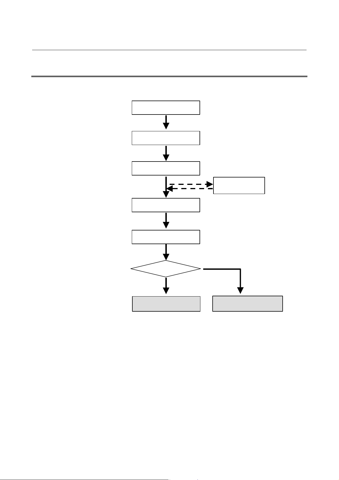
2.1 WORKFLOW
The workflow of a cutting cycle is as follows.
Setting of workpiece
coordinate system
Setting of spindle speed
Setting of feedrate
Selection of tool
(Setting of offset)
Input of cutting cycle data
Pressing of cycle start
button
D-CUT>0
Yes
Cutting cycle with
automatic in-feeding
No
Cutting cycle with manual
in-feeding
- 52 -
Page 65

B-64254EN/06 CUTTING CYCLE 2.OPERATION
Each step of the workflow is described below.
(1) Setting of workpiece coordinate system
For details, see Part II, Chapter 3, "SETTING OF
COORDINATE SYSTEM".
(2) Setting of spindle speed
For details, see Part II, Chapter 4, " SETTING OF SPINDLE
INFORMATION".
(3) Setting of feedrate
For details, see Section 2.2, "SETTING THE FEEDRATE".
(4) Selection of tool
If necessary, set the tool.
For details, see Part II, Chapter 5, " SETTING OF TOOL
INFORMATION".
(5) Input of cutting cycle data
For details, see Sections 2.3 to 2.6.
(6) Pressing of cycle start
Press the cycle start button on the machine operator's panel.
The created cutting cycle is executed to cut the workpiece.
- 53 -
Page 66
2.OPERATION CUTTING CYCLE B-64254EN/06
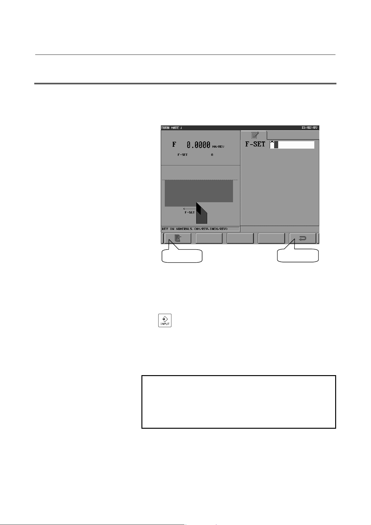
2.2 SETTING THE FEEDRATE
It is necessary to set the feedrate before executing any cutting cycle.
If you push the feedrate display area on the base screen, the feedrate
setting screen is displayed.
[SET] key
Feedrate setting screen
The operation method is as follows.
(1) Input the desired federate of the cutting cycle (mm/rev or
inch/rev) into the data area of F-SET, then push the [INPUT]
[RET] key
) key.
(
(2) Push the [SET] key.
(3) When the setting is done, the specified value of the feedrate
appears in the display area in the upper left side of the screen.
(The value displayed next to F in the upper left side represents
the CNC-specified feedrate modal data.)
NOTE
1 The unit of the federate can be in mm/rev or
inch/rev.
2 If the feedrate is specified in the input data screen
of each cutting cycle, then it is not necessary to set
the feedrate on the feedrate setting screen.
- 54 -
Page 67
B-64254EN/06 CUTTING CYCLE 2.OPERATION
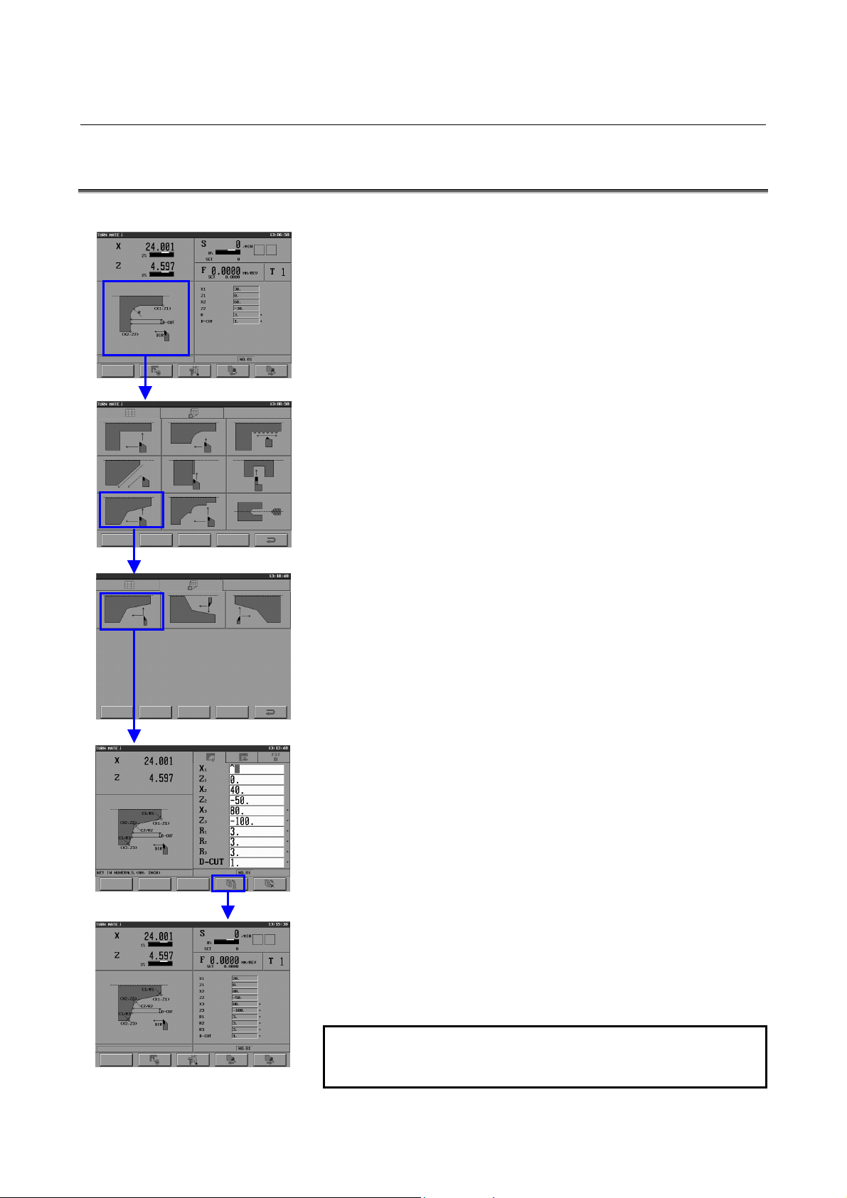
2.3 CREATING A NEW CUTTING CYCLE
The workflow to create a new cutting cycle is described below.
(1) Push the guidance drawing on the base screen to display the
cutting cycle selection screen.
(2) To select the desired cycle menu, push the corresponding
drawing on the cutting cycle selection screen (CYCLE tab).
(3) To select the desired cycle, push the corresponding drawing on
the cutting cycle selection screen (DETAIL tab).
(4) When the cycle input data screen (NOTE) is displayed, fill in the
necessary data.
(5) Push the [SAVE] key to save the data and to return to the base
screen.
NOTE
The layout of the cycle input data screen is as
follows.
- 55 -
Page 68

2.OPERATION CUTTING CYCLE B-64254EN/06
(1) Current
position
(2) Guidance
drawing
(7) [CLEAR] key for data
initialization
(3) [FIG.] tab
(5) [SAVE] key for data
saving
Cycle input data screen
[METH.] tab
[COND.] tab
(4) Cycle data
(6) [CAN] key for data
cancellation
(1) Current position
The current position is indicated in the same way as in the base
screen.
(2) Guidance drawing
In this area of the screen, the guidance drawing of the selected
cutting cycle is displayed. A selection button may be presented
depending on the input data item. When a button is displayed,
press the button on the touch panel or select it with the button
cursor, and then input data.
(3) Tabs
The following 3 tabs - [FIG.], [METH.], and [COND.] - are
provided. Each tab has its own input data items for the cutting
cycle.
[FIG.] : Input data items related to geometry (positions,
dimenstions, etc.)
[METH.] : Input data items related to the cutting method
(cutting direction, finishing amount, etc.)
[COND.] : Input data items related to the cutting conditions
(spindle speed, feedrate, etc.)
(4) Cycle data
This area of the screen displays the data items you need to input
to execute the cutting cycle and the fields for inputting the data.
An unnecessary item has an asterisk (*) to the right of its data
input field.
- 56 -
Page 69

B-64254EN/06 CUTTING CYCLE 2.OPERATION
(5) Soft key for data saving [SAVE]
If you enter necessary data in the data input field and push the
[INPUT] (
) key, the input of the data is confirmed. After
that, push the [SAVE] key to save the input data to memory and
to return to the base screen.
(6) Soft key for data cancellation [CAN]
Push the [CAN] key to cancel the input of the data and to return
to the base screen.
(7) Soft key for data initialization [CLEAR]
Push the [CLEAR] key to clear the input data and to return to the
base screen.
- 57 -
Page 70
2.OPERATION CUTTING CYCLE B-64254EN/06
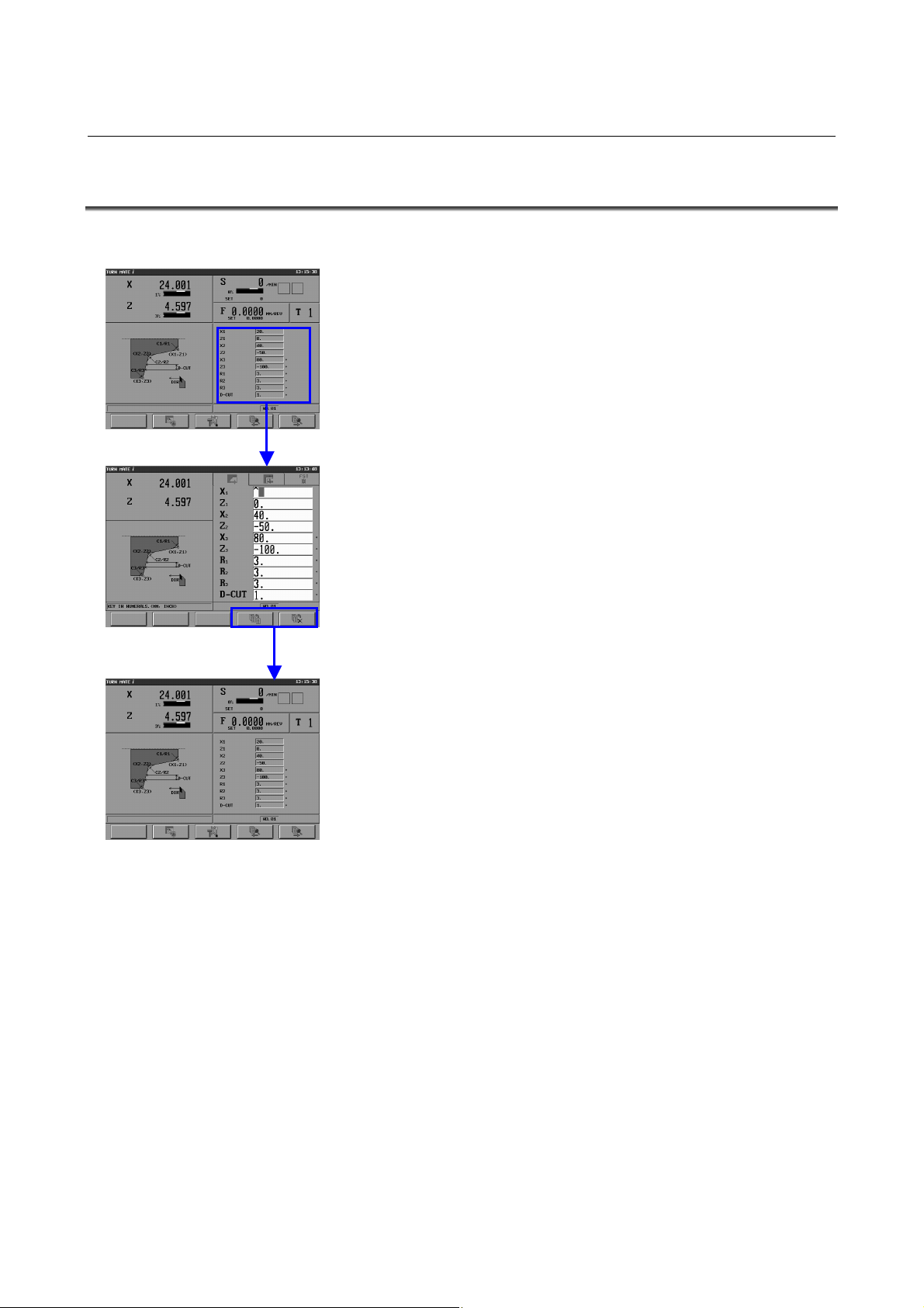
2.4 EDITING A CUTTING CYCLE
The workflow to edit a cutting cycle is described below.
(1) Push the cycle data area on the base screen to display the input
data screen for the cutting cycle.
(2) In the cycle input data screen, edit the data as necessary.
(3) Push the [SAVE] key to save the data and to return to the base
screen.
- 58 -
Page 71

B-64254EN/06 CUTTING CYCLE 2.OPERATION
2.5 SELECTING A CUTTING CYCLE
The workflow to select a cutting cycle is described below.
(1) Push the cycle memory position number display area on the base
screen to display the cycle memory position screen (NOTE).
(2) Select a cycle memory position number by pushing the cycle
memory position button or moving the cursor with the
[↑][↓][←][→] keys.
(In the example at the left, cycle memory position number 9,
thread cutting, is selected.)
The content of the selected cutting cycle is displayed at the
bottom of the screen.
(3) Push the [SELECT] key to return to the base screen, where the
cutting cycle you select in (2) will be selected.
Remark)
You can also select a cutting cycle by using the cycle memory
position soft keys [←] and [→] on the base screen.
NOTE
The layout of the cycle memory position screen is
as shown on the next page.
- 59 -
Page 72

2.OPERATION CUTTING CYCLE B-64254EN/06
(1) Cycle memory
position button
(2) Cycle name
and cutting
condition
(3) Input buffer
(4) [SELECT] key for
cycle selection
Cycle memory position screen
(1) Cycle memory position button
There are 40 buttons. If you push a desired button, the specified
(2) Cycle name and cutting condition display
This area displays the cycle name and cutting condition of the
The cycle name and cutting condition are not displayed if there is
(3) Input buffer
This area displays the numerical values that are input with the
(4) Cycle selection soft key
Push the [SELECT] key to select the specified cutting cycle and
(5) Cycle deletion soft key
Push the [DEL] key to delete the specified cutting cycle and to
(6) Return soft key
Push the [RET] key to return to the base screen.
(5) [DEL] key for cycle
deletion
(6) [RET] key for
returning
cutting cycle is called and the base screen is displayed. The icon
which represents the type of the stored cycle is displayed on the
button. The icon is not displayed on the button if there is no
cycle.
cycle highlighted by the cursor.
no cycle.
MDI key. This area is used to delete multiple cutting cycles.
to return to the base screen.
clear the icon from the cycle memory position button.
- 60 -
Page 73

B-64254EN/06 CUTTING CYCLE 2.OPERATION
2.6 DELETING A CUTTING CYCLE
The workflow to delete a cutting cycle is described below.
(1) Push the cycle memory position number display area on the base
screen to display the cycle memory position screen.
(2) Specify the cutting cycle you want to delete. There are two
methods to specify a cutting cycle, as described below. (The
example at the left uses the method of (b).)
(a) Pressing the cycle memory position button of the cycle to
be deleted
The cutting cycle corresponding to the pressed button is
specified. No more than one cycle can be specified.
(b) Inputting the cycle memory position number of the cycle to
be deleted, by using the MDI keys (NOTE)
One or more cutting cycles can be specified. Using the MDI
keys, input the cycle memory position number of each cycle
to be deleted in the input buffer field.
(3) Pushing the [DEL] soft key displays the deletion confirmation
window. In addition, the buttons of the specified cycle memory
position numbers are displayed in dark gray.
(4) If the [YES] soft key is pressed, the deletion confirmation
window closes and the data of the specified cycles are deleted,
clearing the icons from the cycle memory position buttons.
(Pushing the [NO] soft key closes the deletion confirmation
window without deleting any cutting cycle data.)
- 61 -
Page 74

2.OPERATION CUTTING CYCLE B-64254EN/06
NOTE
When you input cycle numbers in the input buffer
field using the MDI keys, the input format is as
follows.
(1) No input
If nothing is input in the input buffer, then the cycle on
which the cursor is currently positioned is selected.
(2) Specification of one cycle number
Format : X
If a number (X) is input, the cycle at position "X" is
selected.
(3) Specification of multiple cycles
Format : X1, X2, ...
If two or more numbers (X1, X2, ...) are input, each
delimited by a comma, the cycles at positions "X1", "X2",
etc. are selected.
(4) Range specification
Format : XS-XE
If two numbers are input, concatenated with a hyphen, the
cycles from positions "XS" to "XE" are selected.
(5) Combination of multiple specification and range
specification
Format : X1, X2, XS-XE
It is also possible to combine the selection of multiple
cycles with the selection of a range of cycles.
(6) Input other than the above mentioned
If any invalid characters, such as non-alphabetic letters,
numbers outside the 1-40 range, and signs other than
commas and hyphens, are input, the message "INPUT
VALUE IS NOT CORRECT" is displayed.
- 62 -
Page 75

B-64254EN/06 CUTTING CYCLE 2.OPERATION
2.7 NOTES
Before operating TURN MATE i, carefully read the following notes
on cutting cycles.
2.7.1 Inhibition of Operation
If a program is running on the NC side when you switch to the TURN
MATE i screen, you cannot set data for TURN MATE i or execute a
cutting cycle. For safety reasons, the operation of TURN MATE i is
prohibited in any of the following conditions:
(1) PMC signal OP is on.
(2) PMC signal SPL is on.
(3) PMC signal AL is on.
(4) An operator message is displayed.
2.7.2 Manual Intervention during Cutting Cycles
You cannot stop an ongoing cutting cycle and execute manual
intervention.
WARNING
Executing manual intervention during a cutting
cycle can lead to unexpected behavior of the
system. That may cause the tool to collide with the
workpiece or machine, potentially injuring the user
and/or damaging the equipment.
2.7.3 Tool Nose Radius Compensation
The tool path of TURN MATE i is generated based on a compensated
value (tool nose radius) that takes into account the roundness of the
tool nose. Therefore, the tool nose radius compensation command
(G41 or G42) cannot be executed during a cutting cycle.
WARNING
If the tool nose radius compensation command
(G41 or G42) is specified before a cutting cycle,
TURN MATE i cancels it automatically (G40) when
the cycle begins.
- 63 -
Page 76

3.FACE CYCLE CUTTING CYCLE B-64254EN/06
3 FACE CYCLE
This chapter consists of the following sections.
3.1 OUTLINE...................................................................................65
3.2 TOOL CUTTING MOTIONS....................................................66
3.3 INPUT DATA ............................................................................69
- 64 -
Page 77
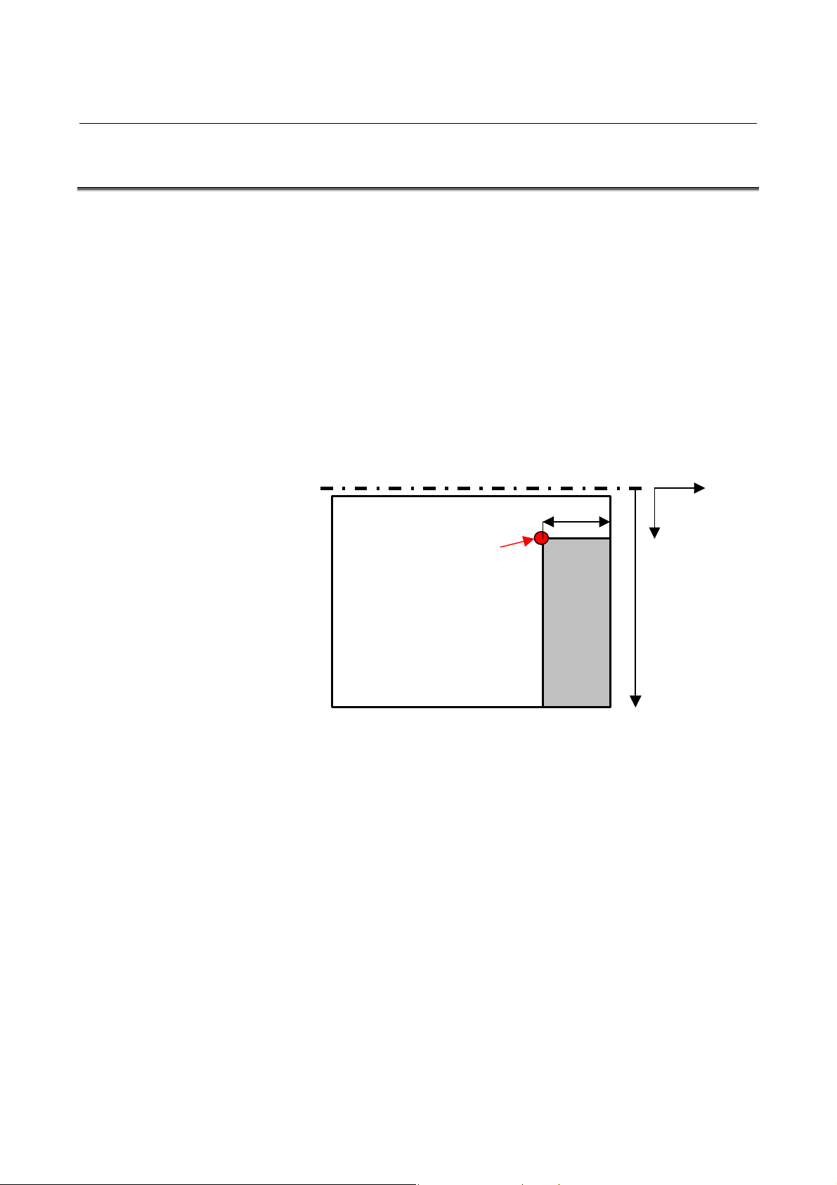
B-64254EN/06 CUTTING CYCLE 3.FACE CYCLE
3.1 OUTLINE
The face cycle is characterized by the following properties.
(1) Rough cutting where turning is done on a face figure in the -X
axis direction
(2) The face area to cut is defined by an cutting end point (X and Z),
cutting start point (X), and cutting clearance.
(3) When the input value of D-CUT is 0, it is possible to machine by
manual in-feeding (a single in-feed machining by the tool).
(4) When the input value of D-CUT is larger than 0, it is possible to
machine by automatic in-feeding (the cutting cycle begins at the
cutting start point).
(5) It is possible to change the tool number, feedrate, and spindle
speed, which are set in the spindle speed setting screen, feedrate
setting screen, and tool selection screen, respectively.
Clearance
+Z
Cutting end point
Workpiece
Cutting
area
+X
Cutting start
point X
coordinate
- 65 -
Page 78
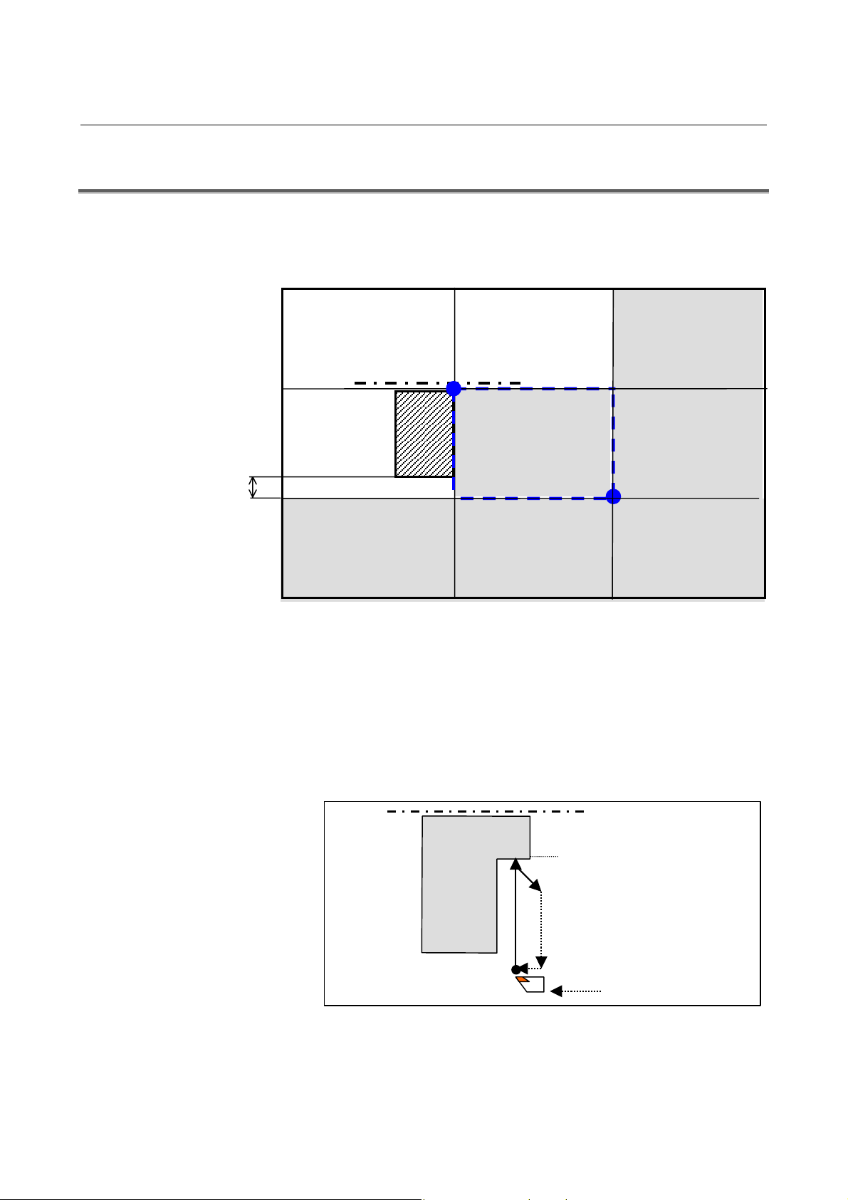
3.FACE CYCLE CUTTING CYCLE B-64254EN/06
g
3.2 TOOL CUTTING MOTIONS
1. Determining the Cutting Cycle Based on the Tool Position
Shown below is the relationship between the tool cutting motions and
the figure and the tool position at the time cycle start is pressed.
Cutting not
possible
[A]
Cutting not
possible
[D]
Clearance
Cutting
possible
[G]
2. Cutting Cycle with Manual In-Feeding (D-CUT=0)
(When the Tool Is Positioned in [H])
(1) The tool moves from the current position in cutting feedrate in
the X axis direction until the edge of the programmed figure is
reached.
(2) The tool retracts in cutting feedrate in the XZ axis direction by
the escape amount (specified in parameter No. 9212).
(3) The tool returns to the initial position in rapid traverse in the X
axis direction and then stops.
Cutting not
possible
[B]
Possible only with the
cutting cycle with
manual in-feeding
[E]
Cutting
possible
[H]
Cutting
possible
[C]
Cutting
possible
[F]
Cutting
possible
[I]
Final
fi
ure
Current tool position
- 66 -
Page 79
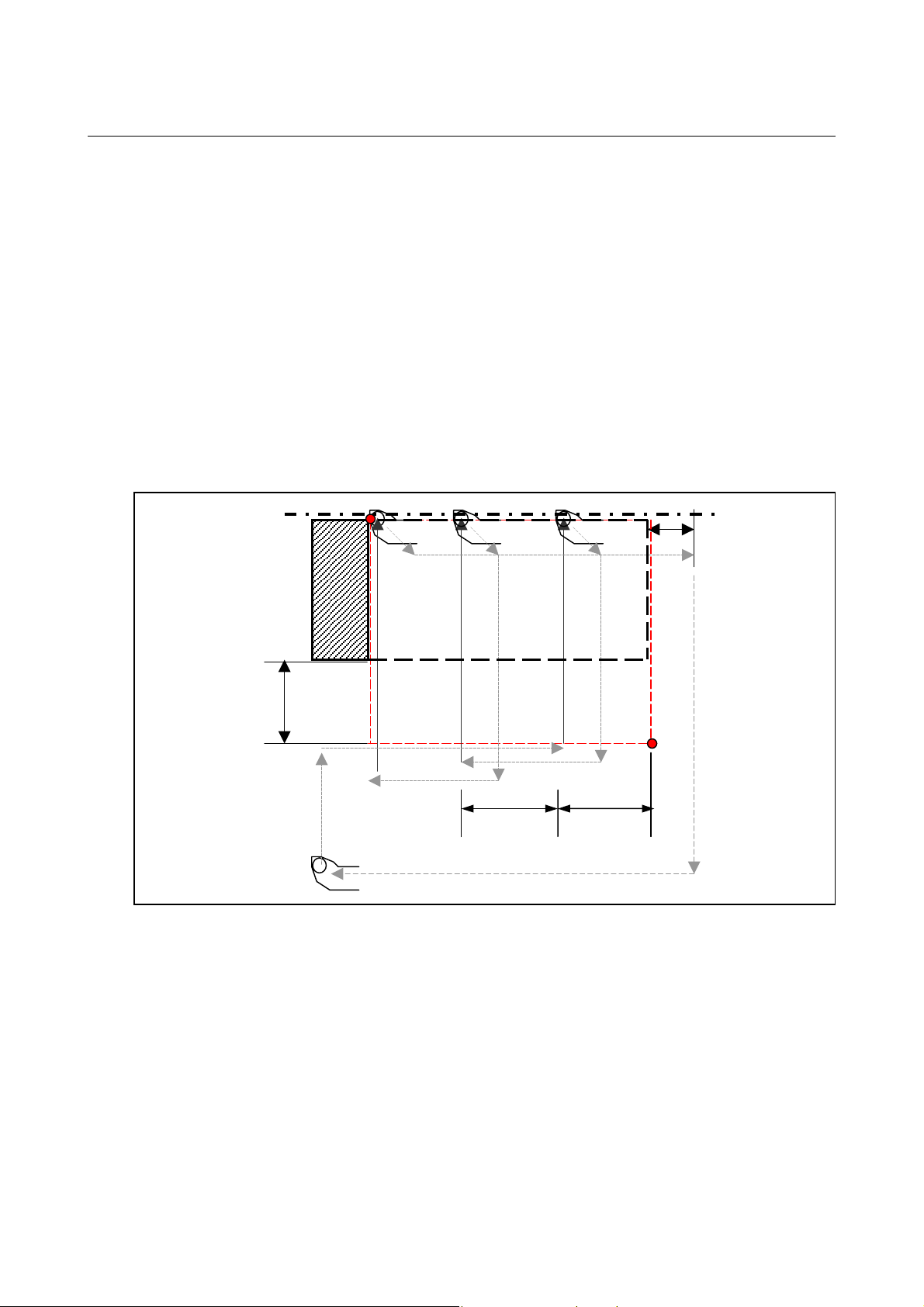
B-64254EN/06 CUTTING CYCLE 3.FACE CYCLE
3. Entire Area Cutting Cycle with Automatic In-Feeding (D-CUT>0)
(When the Tool Is Positioned in [C], [F], [G], or [I])
(1) The tool moves to the cutting start point in rapid traverse, first in
the X axis direction and then in the Z axis direction.
Steps (2) and (3) are the same as the cutting cycle with manual
in-feeding.
(4) The tool moves in the axis direction in rapid traverse by the
depth of cut (D-CUT).
(5) Steps (2) to (4) are repeated until the final cut surface is reached.
After the final in-feed machining, the tool retracts in the XZ axis
direction by the escape amount (specified in parameter No. 9212)
and then moves in rapid traverse by the Z_max+Z axis clearance.
(6) The tool returns to the initial position in rapid traverse, first in
the X axis direction and then in the Z axis direction, and then
stops.
Z axis
direction
clearance
X axis
direction
clearance
D-CUTD-CUT
- 67 -
Page 80

3.FACE CYCLE CUTTING CYCLE B-64254EN/06
4. Partial Area Cutting Cycle with Automatic In-Feeding (D-CUT>0)
(When the Tool Is Positioned in [H])
(1) The tool moves to the cutting start point in rapid traverse in the X
axis direction.
Steps (2) to (6) are the same as the cutting cycle with automatic
in-feeding.
X axis direction
clearance
Z axis
direction
clearance
D-CUT
- 68 -
Page 81
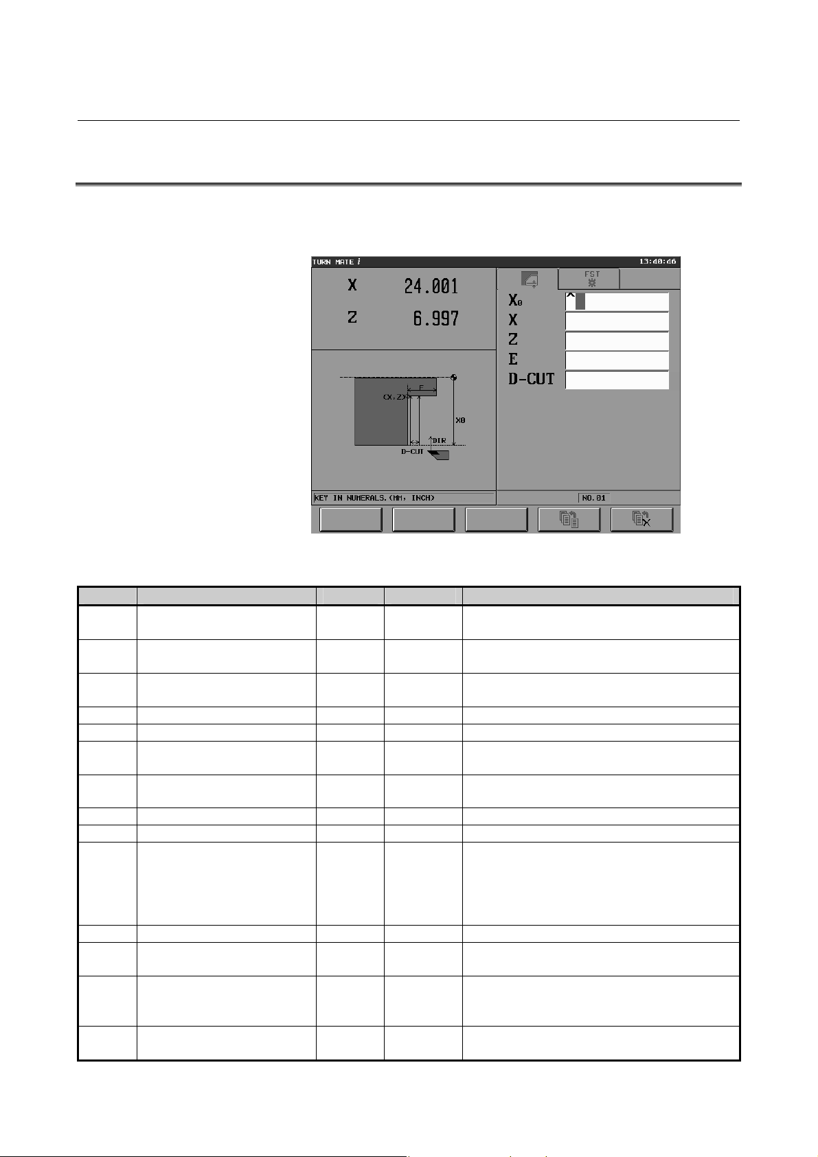
B-64254EN/06 CUTTING CYCLE 3.FACE CYCLE
3.3 INPUT DATA
If face cycle is selected in the cutting cycle selection screen, the cycle
input data screen is displayed as follows.
The items to input are listed below.
Item Meaning Tab Mandatory Note
X0 X coordinate of the cutting
start point
X X coordinate of the cutting
end point
Z Z coordinate of the cutting
end point
E Width of the area to cut FIG.
D-CUT Depth of cut FIG.
XA X coordinate of the approach
position
ZA Z coordinate of the approach
position
T Tool number COND.
F Feedrate COND.
CSS Specify constant surface
speed with the button on the
touch panel.
[ON] : Disable (1)
[OFF] : Enable (2)
S Spindle speed COND.
S-MAX Maximum spindle speed COND.
S-DIR Spindle rotation direction
[NORMAL] : Normal (1)
[REVERSE] : Reverse (2)
G Specify the gear number with
the button on the touch panel.
FIG.
FIG.
FIG.
METH.
METH.
COND.
COND.
COND.
○
○
○
○
○
×
×
×
×
×
×
×
×
×
Absolute coordinate
Absolute coordinate (NOTE)
Absolute coordinate
Displayed only when parameter No. 9202#2 = 1.
Displayed only when parameter No. 9202#2 = 1.
There is no default.
There is no default.
There is no default.
There is no default.
Displayed only when CCS = 1.
There is no default.
The default is 1 (NORMAL).
Displayed only when parameter No. 9202#1 = 1.
Refer to parameter Nos. 9213, 9214, and 9215.
The value range is 1 to 4; there is no default.
- 69 -
Page 82

3.FACE CYCLE CUTTING CYCLE B-64254EN/06
NOTE
By enabling the optional function and the
parameter shown below, you can input a negative
value for the cutting end point (X).
• Optional function: Cutting cycle extension
• Parameter: No. 9203 #1 (SFC) = 1
When the above optional function and parameter
are enabled, 0 is always assumed for the virtual
tool nose position and radius when generating the
tool path. Since the X coordinate range check is
not made, make sure that the negative value you
input is smaller than the tool nose radius.
- 70 -
Page 83

B-64254EN/06 CUTTING CYCLE 4.CHAMFER CYCLE
4 CHAMFER CYCLE
This chapter consists of the following sections.
4.1 OUTLINE...................................................................................72
4.2 TOOL CUTTING MOTIONS....................................................74
4.3 INPUT DATA ............................................................................81
- 71 -
Page 84

4.CHAMFER CYCLE CUTTING CYCLE B-64254EN/06
4.1 OUTLINE
There are three types of chamfer cycle - outer face chamfer, outer
back chamfer, and inner chamfer. The chamfer cycle is characterized
by the following properties.
(1) Cutting where the tool is turned along the outside of the figure
that can be defined by the corner coordinates and the corner
rounding (arc) or corner chamfering
(2) Either rounding (arc) or chamfering can be set for the corner.
(3) Rough cutting can be done along the final figure (corner
rounding or chamfering).
(4) When the input value of D-CUT is 0, it is possible to machine by
manual in-feeding (a single in-feed machining by the tool).
(5) When the input value of D-CUT is larger than 0, it is possible to
machine by automatic in-feeding (the cutting cycle begins at the
cutting start point).
(6) It is possible to change the tool number, feedrate, and spindle
speed, which are set in the spindle speed setting screen, feedrate
setting screen, and tool selection screen, respectively.
- 72 -
Page 85

B-64254EN/06 CUTTING CYCLE 4.CHAMFER CYCLE
Outer face chamfer R/chamfer C
Workpiece
R/C
45°
Corner
coordinates
+Z
+X
Outer back chamfer R/chamfer C
+Z
Inner chamfer R/chamfer C
R/C
Corner coordinates
Workpiece
45°
Workpiece
Corner coordinates
45°
+X
+Z
+X
R/C
- 73 -
Page 86

4.CHAMFER CYCLE CUTTING CYCLE B-64254EN/06
p
p
p
p
p
p
p
p
4.2 TOOL CUTTING MOTIONS
There are six types of chamfer cutting. However, since the tool cutting
motion of each cycle is identical except that the cutting area is
symmetrical horizontally (outer face chamfer and outer back chamfer)
or vertically (outer face chamfer and inner chamfer), this section
describes the outer chamfer C cycle as an example.
1. Determining the Cutting Cycle Based on the Tool Position
Shown below is the relationship between the tool cutting motions and
the figure and the tool position at the time cycle start is pressed. In the
case of a cutting cycle with manual in-feeding, 0 is specified for the
depth of cut and the tool moves to [C] or [F] before the cycle starts. If
the cycle starts with a value specified for the depth of cut and the tool
moved to [F], automatic cutting is performed from the current position
(halfway through the cutting area).
Cutting not
ossible
[A]
Cutting not
Cutting
ossible
[B]
Cutting
ossible
[C]
[D]
Cutting not
possible
Cutting
ossible
[G]
Cutting not
ossible
Cutting
ossible
[H]
Cutting
ossible
[F]
[E]
Cutting
ossible
[I]
- 74 -
Page 87

B-64254EN/06 CUTTING CYCLE 4.CHAMFER CYCLE
2. Cutting Cycle with Manual In-Feeding (D-CUT=0)
(When the Tool Is Positioned in [E] or [F])
(1) The tool moves from the cutting start point in cutting feedrate in
the Z axis direction until position (XS, Z) is reached.
(2) The tool moves in cutting feedrate along the input figure until
position (X, Zn) is reached.
(3) The tool moves in cutting feedrate in the X axis direction over
the distance equal to clearance.
(4) The tool returns to the initial position in rapid traverse, first in
the Z axis direction and then in the X axis direction, and then
stops.
Clearance
C
R
Clearance
(2)
(X, Zn)
(3)
(X, Zn) (X, Z)
(3)
Clearance
(X, Z)
Clearance
(2)
(1)
(4)
(1)
(4)
(XS, ZS)
(4)
(XS, ZS)
(4)
- 75 -
Page 88

4.CHAMFER CYCLE CUTTING CYCLE B-64254EN/06
3. Cutting Cycle with Manual In-Feeding (D-CUT=0)
(When the Tool Is Positioned in [C])
(1) The tool moves from the cutting start point in rapid traverse until
position (Xm, ZS) is reached.
(2) The tool moves in cutting feedrate in the Z axis direction until
position (Xm, Z) is reached.
(3) The tool moves in cutting feedrate along the input final figure
until position (X, Zm) is reached.
In the case of corner rounding, overcutting is done in the -Z axis
direction.
(4) The tool moves in cutting feedrate in the X axis direction over
the distance equal to clearance.
(5) The tool returns to the initial position in rapid traverse, first in
the Z axis direction and then in the X axis direction, and then
stops.
C
(3)
Clearance
(X, Zm)
(4)
R
(3)
Clearance
(4)
Overcut
(XS, ZS)
(1)
(Xm, Z)
(2)
(5)
(X, Z)
(5)
(XS,ZS)
(1)
(2)
(5)
(3)
(X, Z) (X, Zm)
(5)
- 76 -
Page 89

B-64254EN/06 CUTTING CYCLE 4.CHAMFER CYCLE
4. Entire Area Cutting Cycle with Automatic In-Feeding (D-CUT>0)
(When the Tool Is Positioned in [C], [G], [H], or [I])
(1) The tool moves from the cutting start point in rapid traverse, first
in the Z axis direction and then in the X axis direction, until
position (XS, ZS) is reached.
(2) The tool moves in cutting feedrate in the Z axis direction until
position (XS, Z) is reached.
(3) The tool moves in cutting feedrate along the input figure until
position (X, Zn) is reached.
(4) The tool moves in cutting feedrate in the X axis direction over
the distance equal to clearance.
(5) The tool moves in rapid traverse in the Z axis direction until
position ZS is reached and then in the X axis direction until
position XS is reached.
(6) Then, the tool moves in cutting feedrate in the X axis direction
by the depth of cut (D-CUT).
(7) Then, steps (2) to (6) are repeated until one of the following
points is reached:
In the case of corner chamfer: (X-C, Z-C)
In the case of corner rounding: (X-R, Z-R); overcut when the
final figure is cut (the depth of overcut is specified by parameter
No. 9212).
- 77 -
Page 90
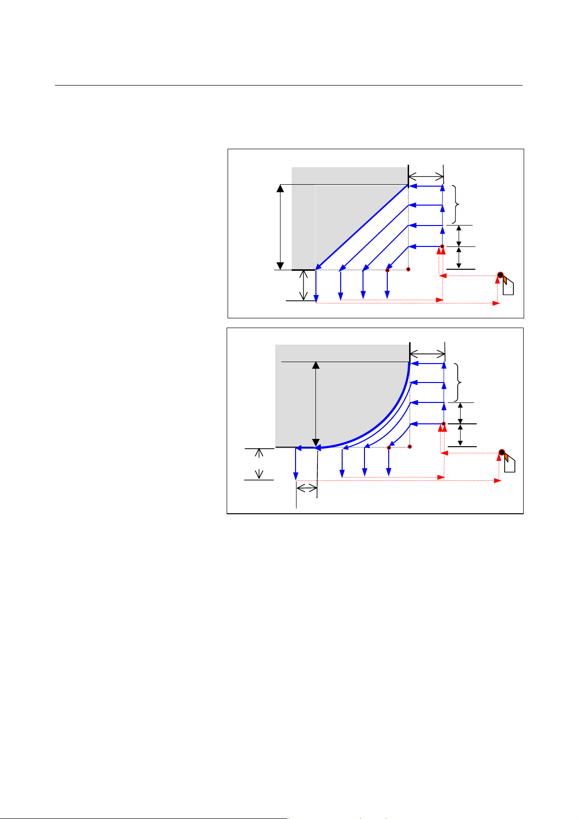
4.CHAMFER CYCLE CUTTING CYCLE B-64254EN/06
(1)
(8) The tool returns to the initial position in rapid traverse, first in
the Z axis direction and then in the X axis direction, and then
stops.
Clearance
C
(X, Zn)
Clearance
(8)
R
(X, Zn)
Clearance
(X, Z)
(4)
(5)
Clearance
(X, Z)
(4)
(5)
(6)
(XS, ZS)
(2) (3)
(1)
(5)
(6)
(XS, ZS)
(2) (3)
(5)
(7)
(1)
(7)
(1)
D-CUT
D-CUT
(8)
D-CUT
D-CUT
(8)
Overcut
(8)
- 78 -
Page 91

B-64254EN/06 CUTTING CYCLE 4.CHAMFER CYCLE
5. Partial Area Cutting Cycle with Automatic In-Feeding (D-CUT>0)
(When the Tool Is Positioned in [F])
(1) The tool moves from the cutting start point in rapid traverse in
the Z axis direction until position (XS, ZS) is reached.
(2) The tool moves in cutting feedrate in the Z axis direction until
position (XS, Z) is reached.
(3) The tool moves in cutting feedrate along the input figure until
position (X, Zn) is reached.
(4) The tool moves in cutting feedrate in the X axis direction over
the distance equal to clearance.
(5) The tool moves in rapid traverse in the Z axis direction until
position ZS is reached and then in the X axis direction until
position XS is reached.
(6) Then, the tool moves in cutting feedrate in the X axis direction
by the depth of cut (D-CUT).
(7) Then, steps (2) to (6) are repeated until one of the following
points is reached:
In the case of corner chamfer: (X-C, Z-C)
In the case of corner rounding: (X-R, Z-R); overcut when the
final figure is cut.
- 79 -
Page 92

4.CHAMFER CYCLE CUTTING CYCLE B-64254EN/06
(8) The tool returns to the initial position in rapid traverse, first in
the Z axis direction and then in the X axis direction, and then
stops.
C
Clearance
(X, Zn) (X, Z)
(4) (5)
(8)
R
Clearance
(3)
Clearance
(6)
(2)
(XS, ZS)
(5)
(6)
(2)
(XS, ZS)
(7)
D-CUT
(1)
(8)
(7)
D-CUT
(1)
Clearance
Overcut
(3)
(X, Zn) (X, Z)
(4)
(8)
(5)
(5)
(8)
- 80 -
Page 93
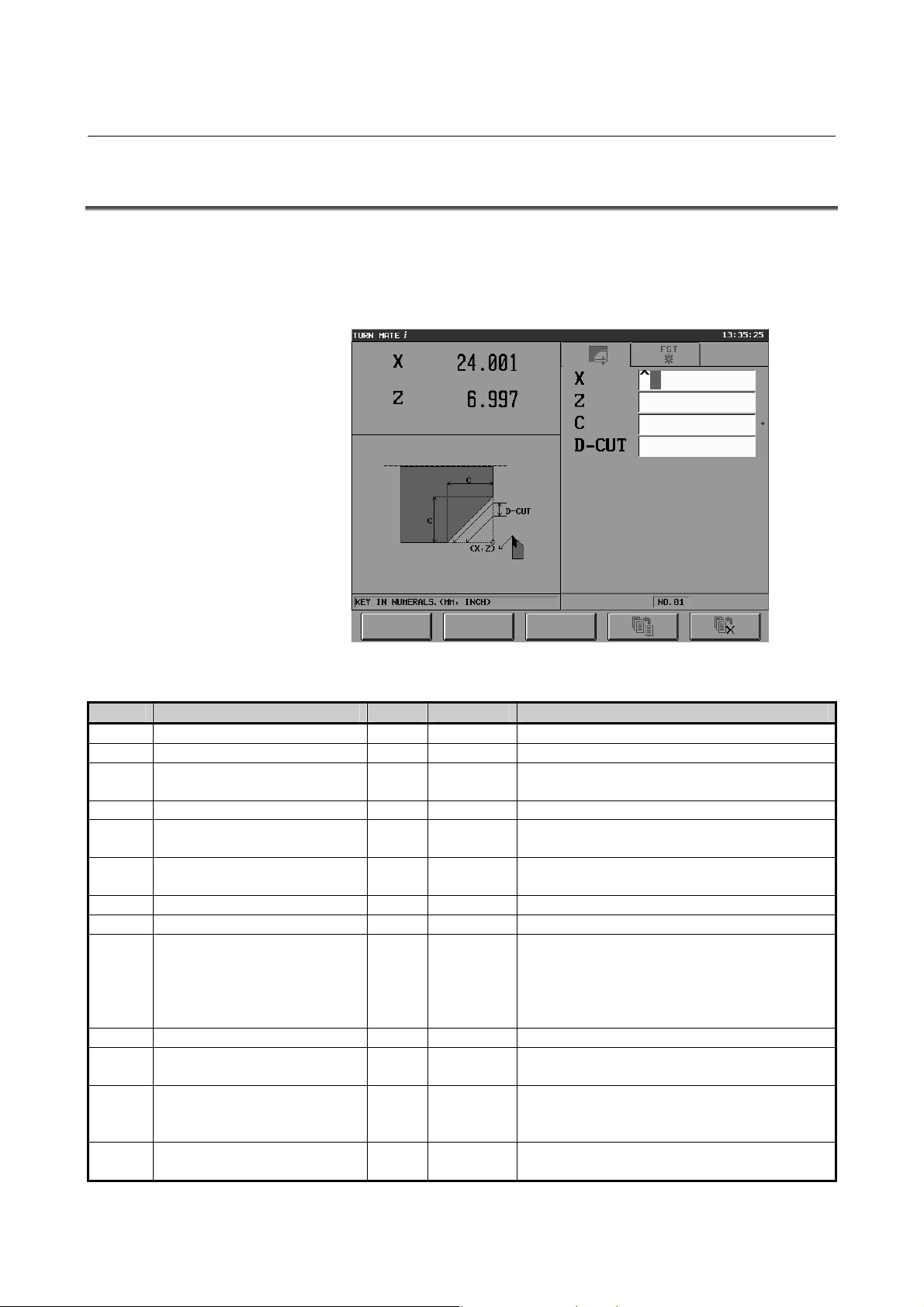
B-64254EN/06 CUTTING CYCLE 4.CHAMFER CYCLE
4.3 INPUT DATA
There are six types of chamfer cutting. However, since the input data
screen of each cycle is identical except for the guidance drawings, this
section describes the input data screen for the outer chamfer C cycle
as an example.
The items to input are listed below.
Item Meaning Tab Mandatory Note
X X coordinate of the corner FIG.
Z Z coordinate of the corner FIG.
R/C Corner rounding radius/amount
of chamfering
D-CUT Depth of cut FIG.
XA X coordinate of the approach
position
ZA Z coordinate of the approach
position
T Tool number COND.
F Feedrate COND.
CSS Specify constant surface speed
with the button on the touch
panel.
[ON]: Disable (1)
[OFF]: Enable (2)
S Spindle speed COND.
S-MAX Maximum spindle speed COND.
S-DIR Spindle rotation direction
[NORMAL] : Normal (1)
[REVERSE] : Reverse (2)
G Specify the gear number with
the button on the touch panel.
FIG.
METH.
METH.
COND.
COND.
COND.
○
○
○
○
×
×
×
×
×
×
×
×
×
Absolute coordinate
Absolute coordinate
There is no default.
Displayed only when parameter No. 9202#2 = 1.
Displayed only when parameter No. 9202#2 = 1.
There is no default.
There is no default.
There is no default.
There is no default.
Displayed only when CCS = 1.
There is no default.
The default is 1 (NORMAL).
Displayed only when parameter No. 9202#1 = 1.
Refer to parameter Nos. 9213, 9214, and 9215.
The value range is 1 to 4; there is no default.
- 81 -
Page 94

5.RECTANGULAR CYCLE CUTTING CYCLE B-64254EN/06
5 RECTANGULAR CYCLE
This chapter consists of the following sections.
5.1 OUTLINE...................................................................................83
5.2 TOOL CUTTING MOTIONS....................................................85
5.2.1 Rough Cutting Motions.......................................................85
5.2.2 Finish Cutting Motions........................................................93
5.3 INPUT DATA ............................................................................98
- 82 -
Page 95

B-64254EN/06 CUTTING CYCLE 5.RECTANGULAR CYCLE
5.1 OUTLINE
There are three types of rectangular cycle - outer, inner, and outer
back. The rectangular cycle is characterized by the following
properties.
(1) Cutting where the tool is turned along the inside of the rectangle
(specified by the coordinate values of 2 points)
(2) Either rounding (arc) or chamfering can be set for the corner.
(3) The turning direction can be selected from -Z, +Z, +X, and -X.
(4) Rough cutting is possible allowing the tool to move in parallel
with the Z axis (X axis).
(5) Finishing cutting is possible allowing the tool to move
counterclockwise along the final figure.
(6) When the input value of D-CUT is 0, it is possible to machine by
manual in-feeding (a single in-feed machining by the tool).
(7) When the input value of D-CUT is larger than 0, it is possible to
machine by automatic in-feeding (the cutting cycle including
rough or finishing cutting begins at the cutting start point).
(8) It is possible to change the tool number, feedrate, and spindle
speed, which are set in the spindle speed setting screen, feedrate
setting screen, and tool selection screen.
CAIUTION
For the outer rectangular cycle, the figure must be
increasing monotonously. For the outer back or
inner rectangular cycle, the figure must be
decreasing monotonously.
- 83 -
Page 96

5.RECTANGULAR CYCLE CUTTING CYCLE B-64254EN/06
Outer rectangular/rectangular R/rectangular C
Workpiece
+Z
C
Corner
R
2nd point
Cutting area
Outer back rectangular/rectangular R/rectangular C
Workpiece
1st point
Cutting area
C
Corner
R
2nd point
Inner rectangular/rectangular R/rectangular C
2nd point
1st point
+X
+Z
+X
+Z
Corner
Workpiece
R
C
Cutting area
1st point
+X
- 84 -
Page 97

B-64254EN/06 CUTTING CYCLE 5.RECTANGULAR CYCLE
p
p
p
5.2 TOOL CUTTING MOTIONS
There are nine types of rectangular cutting. However, since the tool
cutting motion of each cycle is identical except that the cutting area is
symmetrical horizontally (outer and outer back) or vertically (outer
and inner), this section describes the outer rectangular C cycle as an
example.
5.2.1 Rough Cutting Motions
1. Determining the Cutting Cycle Based on the Tool Position
Shown below is the relationship between the tool cutting motions and
the figure and the tool position at the time cycle start is pressed. In the
case of a cutting cycle with manual in-feeding, the tool moves to [F]
or [E] when cutting in the Z direction or to [H] or [E] when cutting in
the X direction.
NOTE
If a cutting cycle with manual in-feeding starts from
[C], [G], or [I], only the final figure is cut once.
Z direction cutting
Clearance
Cutting not
ossible
[A]
Cutting not
ossible
[D] [F]
Cutting
possible
[G]
Cutting not
ossible
[B]
Possible only with the
cutting cycle with
manual in-feeding
[E]
Cutting
possible
[H]
Cutting
possible
[C]
Cutting
possible
Cutting
possible
[I]
- 85 -
Page 98

5.RECTANGULAR CYCLE CUTTING CYCLE B-64254EN/06
p
X direction cutting
Cutting not possible
[A]
Cutting not possible
[B]
Cutting possible
[C]
Cutting possible
Clearance
Cutting not
ossible
[D] [F]
Possible only with the
cutting cycle with
manual in-feeding
[E]
Cutting possible
[I]
[G]
Cutting possible
Cutting possible
[H]
2. Cutting Cycle with Manual In-Feeding (D-CUT=0) in the Z Direction
(When the Tool Is Positioned in [E] or [F])
(1) The tool moves from the current position (cutting start point) in
cutting feedrate, with the finishing amount left, until the input
figure position is reached.
(2) Then, the tool immediately retracts in the XZ axis direction by
the escape amount (specified in parameter No. 9212) and then
moves in rapid traverse in the Z axis direction until the cutting
start point is reached.
(3) The tool returns to the initial position in rapid traverse in the X
axis direction and then stops.
Cutting start
point
- 86 -
Page 99

B-64254EN/06 CUTTING CYCLE 5.RECTANGULAR CYCLE
3. Cutting Cycle with Manual In-Feeding (D-CUT=0) in the Z Direction
(When the Tool Is Positioned in [C], [G], [H], or [I])
(1) The tool moves in rapid traverse from the initial position, first
along the Z axis and then the X axis direction, goes at the Z axis
direction clearance distance (No.9211) from the workpiece.
(2) Cutting is done along the input figure until the end.
(3) The tool moves in cutting feedrate in the X axis direction over
the distance equal to the X axis direction clearance.
(4) The tool returns to the initial position in rapid traverse, first
along the Z axis and then the X axis.
Initial tool position
- 87 -
Page 100
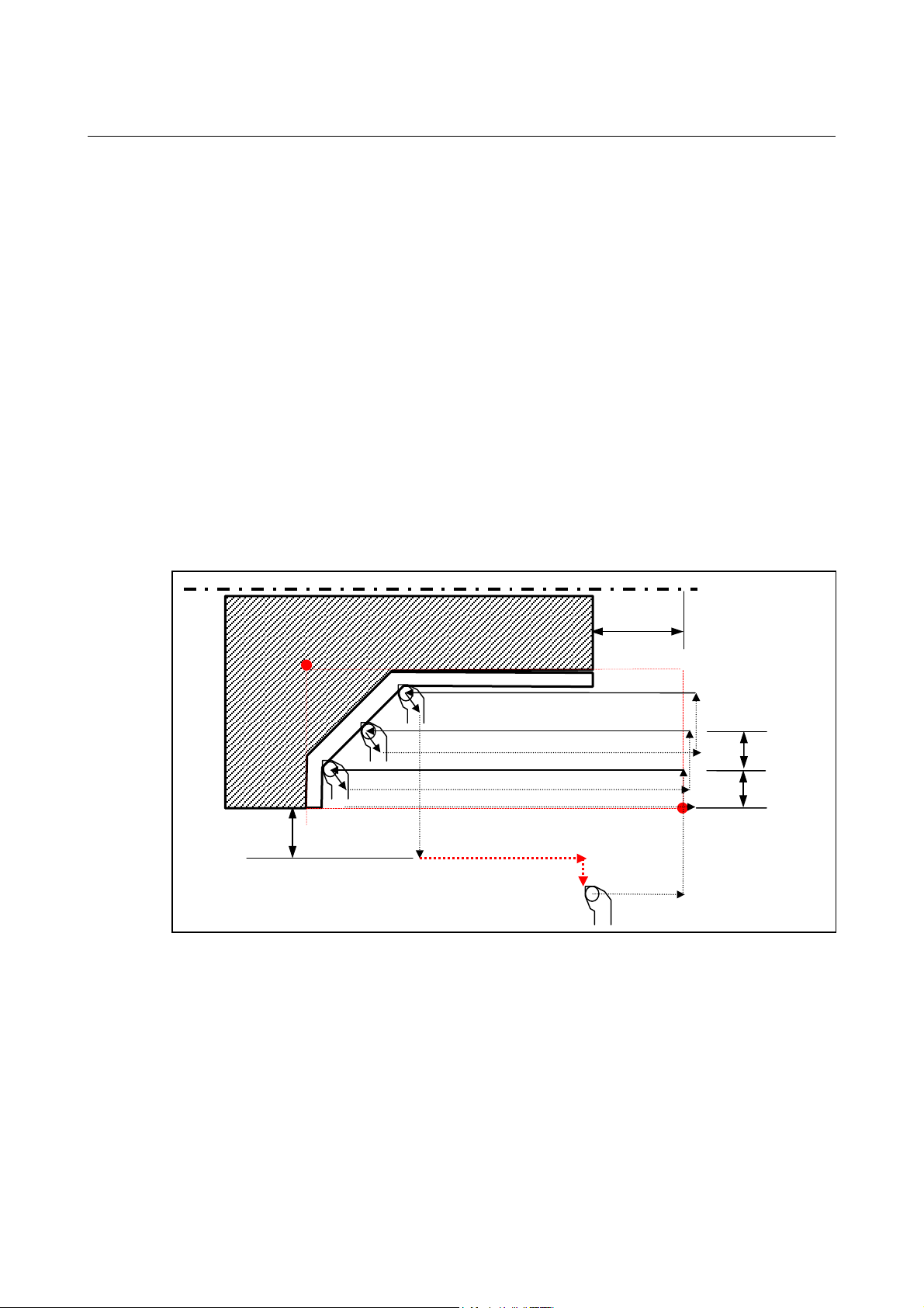
5.RECTANGULAR CYCLE CUTTING CYCLE B-64254EN/06
4. Entire Area Cutting Cycle with Automatic In-Feeding (D-CUT>0) in the Z
Direction
(When the Tool Is Positioned in [C], [G], [H], or [I])
(1) The tool moves in rapid traverse, first in the Z axis direction and
then in the X axis direction, until the cutting start point is
reached.
Steps (2) and (3) are the same as the cycle with manual in-feeding.
(4) The tool moves in rapid traverse in the X axis direction by the
depth of cut (D-CUT).
(5) Steps (2) to (4) are repeated until the bottom end of the X axis is
reached.
After the final in-feed machining, the tool retracts in the XZ axis
direction by the escape amount (specified in parameter No. 9212)
and then goes at the X axis direction clearance distance
(No.9210) from the workpiece.
(6) When performing only rough cutting, the tool returns to the
initial position in rapid traverse, first in the Z axis direction and
then in the X axis direction, and then stops. When doing both
rough and finishing cutting, the tool performs finishing cutting.
X axis direction clearance
Z axis direction
clearance
D-CUT
D-CUT
- 88 -
 Loading...