

Page 1

GE Fanuc Automation
Computer Numerical Control Products
Symbolic CAP T
Basic Module V1
Operator’s Manual
GFZ-62824EN/02 November 1998
Page 2

Warnings, Cautions, and Notes
as Used in this Publication
Warning notices are used in this publication to emphasize that hazardous voltages, currents,
temperatures, or other conditions that could cause personal injury exist in this equipment or
may be associated with its use.
In situations where inattention could cause either personal injury or damage to equipment, a
Warning notice is used.
Caution notices are used where equipment might be damaged if care is not taken.
GFL-001
Warning
Caution
Note
Notes merely call attention to information that is especially significant to understanding and
operating the equipment.
This document is based on information available at the time of its publication. While efforts
have been made to be accurate, the information contained herein does not purport to cover all
details or variations in hardware or software, nor to provide for every possible contingency in
connection with installation, operation, or maintenance. Features may be described herein
which are not present in all hardware and software systems. GE Fanuc Automation assumes
no obligation of notice to holders of this document with respect to changes subsequently made.
GE Fanuc Automation makes no representation or warranty, expressed, implied, or statutory
with respect to, and assumes no responsibility for the accuracy, completeness, sufficiency, or
usefulness of the information contained herein. No warranties of merchantability or fitness for
purpose shall apply.
©Copyright 1998 GE Fanuc Automation North America, Inc.
All Rights Reserved.
Page 3

B-62824EN/02 SAFETY PRECAUTIONS
s-1
SAFETY PRECAUTIONS
This manual includes safety precautions for protecting the user and
preventing damage to the machine. Precautions are classified into Warnings
and Cautions according to their bearing on safety. Also, supplementary
information is described as Notes. Read the Warnings, Cautions, and Notes
thoroughly before attempting to use the machine.
WARNING
Applied when there is a danger of the user being injured or when there
is a danger of both the user being injured and the equipment being
damaged if the approved procedure is not observed.
CAUTION
Applied when there is a danger of the equipment being damaged, if the
approved procedure is not observed.
NOTE
Notes is used to indicate supplementary information other than
Warnings and Cautions.
¡ Read this manual carefully, and store it in a safe place.
NOTE
In this manual, a program used to specify operations of the CNC
machine tool is referred to as "NC data." In CNC machine tool
manuals, such a program may be referred to as a "machining
program," "part program," or "program," in place of "NC data." The
above precautions must also be applied to those programs in a CNC
machine tool manual, assuming that the programs have the same
usage and purpose as those of the NC data as described in this
manual.
Page 4

SAFETY PRECAUTIONS B-62824EN/02
s-2
GENERAL WARNINGS AND CAUTIONS RELATING TO USE WITH A CNC
This chapter presents the safety precautions which must be observed when
the conversational automatic programming function, described in this
manual, is used with the CNC machine tool.
WARNING
(1) Before starting any operation related to the conversational function
(such as preparing NC data or running an NC data program),
thoroughly check the work area to ensure safety. For example, close
the door of the machine, if it is open. Failure to ensure safety may
result in death or serious injury. Operating the machine with
incorrect NC data may result in the tool colliding with the workpiece
and/or machine, possibly causing damage to the machine,
workpiece, and/or the tool itself, or injury to the user.
(2) When the tool offset function is used, before activating the machine,
check the direction and value of the offset to ensure that the tool will
not collide with the workpiece or machine. Any collision may cause
damage to the tool, machine, and/or workpiece, or injury to the user.
(3) Before starting the NC data program prepared using the
conversational function, thoroughly check the NC data to ensure that
the tool path and machining processes are set correctly, and that the
tool will not collide with the workpiece or machine (including the
chuck and tailstock). Before starting a production run, perform a dry
run to ensure that the tool will not collide with the workpiece or
machine (including the chuck and tailstock). For example, start the
NC data program without mounting a workpiece on the machine.
Any collision may cause damage to the tool, machine, and/or
workpiece, or injury to the user.
(4) Before using the conversational function to perform programming,
ensure that all the data required for the conversational function,
including tool data and cutting condition data, is set correctly. If
these data values are not set appropriately, the cutting conditions
required for machining may not be set correctly, possibly causing
damage to the tool, machine, and/or workpiece, or injury to the user.
(5) After pressing the power-on button, do not touch any keys on the
keyboard until the window is displayed. Some keys are specifically
designed for maintenance or other special operations; if any of these
keys is pressed before the window is displayed, the machine may
behave unexpectedly.
Page 5

B-62824EN/02 SAFETY PRECAUTIONS
s-3
GENERAL WARNINGS AND CAUTIONS RELATING TO USE WITH A
PERSONAL COMPUTER
This chapter presents the safety precautions which must be observed when
the software, described in this manual, is used with a personal computer,
and when the prepared NC data(Note) is used with a CNC machine tool.
WARNING
(1) Before using NC data with a CNC machine tool to perform a
production run, ensure that the machine and tool under the control of
the NC data commands will operate safely. If incorrect NC data is
used carelessly, or if correct NC data is handled improperly, the
machine or tool may behave unexpectedly, possibly causing damage
to the machine, tool, and/or workpiece, or injury to the user.
(2) In this software, once NC data has been automatically created,
whether the NC data program runs appropriately for the CNC
machine tool is not checked. When using the NC data with a CNC
machine tool to perform a production run, follow the instructions in
(1) above.
(3) In this software, whether other software for drawing or checking NC
data runs appropriately for the CNC machine tool is not checked.
When using the NC data with a CNC machine tool to perform a
production run, follow the instructions in (1) above.
(4) When even proven NC data is used repeatedly, the contents of the
NC data may have changed when it is input to the CNC machine tool,
due to degradation in the NC data storage, or changes in the
communication facilities for data transfer. When using the NC data
with a CNC machine tool to perform a production run, follow the
instructions in (1) above.
Page 6

B-62824EN/02 PREFACE
p-1
PREFACE
Thank you for purchasing FANUC Symbolic CAP T.
The FANUC Symbolic CAP T software provides total support of all lathing
phases from blank figure creation and parts figure creation through to NC
data creation. To take full advantage of the functions and features of
FANUC symbolic CAP T, users are advised to read and become familiar
with the entire contents of this manual.
FANUC Symbolic CAP T is compatible with Microsoft Windows. This
manual does not attempt to explain basic Windows operations. Those users
who are unfamiliar with Windows should first read the Windows
documentation for an explanation of Windows fundamentals.
FANUC Symbolic CAP T uses the following products, whose copyright is
owned by Microsoft of the USA.
• Microsoft Windows Software Development Kit
• Microsoft Windows Visual C++
• Microsoft Windows Visual Basic
• Microsoft Windows Visual Control Pack
NOTE
Microsoft and Windows are registered trademarks of Microsoft
Corporation of the USA. Visual C++ and Visual Basic are trademarks
of Microsoft Corporation.
Checking the contents of the package
Immediately after opening the package, check that you have received the
following items.
1) Floppy disks
• For OPEN CNC
FANUC Symbolic CAP T Basic module V1 (A08B-9110J550#EN07)
• For Personal computer
FANUC Symbolic CAP T Basic module V1 (A08B-9310J550#EN07)
TM
TM
2) Protector (Only for Personal computer)
FANUC Symbolic CAP T Basic module Protector (A08B-0080-
Page 7

PREFACE B-62824EN/02
p-2
J550#P550)
3) Operator's manual
FANUC Symbolic CAP T Basic module Operator's Manual (this
document)
About this manual
This manual consists of the sections described below.
PREFACE
Describes the use of this manual and related materials.
Also, briefly describes some of the features of FANUC Symbolic CAP
T.
1. SETUP
Describes the environment needed to run FANUC Symbolic CAP T,
and the method of setting up and enabling the use of FANUC
Symbolic CAP T.
2. BASIC OPERATION
Explains how to start and stop FANUC Symbolic CAP T, and
describes its basic operations. Also, briefly describes the functions
provided by the side menu and menu bar.
3. PROGRAMMING EXAMPLE
Provides an example of the operation of FANUC Symbolic CAP T.
4. BLANK FIGURE CREATION
Describes the types of blank figures, and explains their creation.
5. PARTS FIGURE CREATION
Describes how to create parts figure by means of symbolic figure
input.
6. PRE-MACHINING SETTING
Explains how to set the machine's home position and select tooling
data; these operations must be completed before machining definition
can be performed.
7. MACHINING DEFINITION
Describes the specification of machining types, machining area, and
machining conditions, based on the blank and part figures. Also
explains how these items can be determined automatically.
Page 8

B-62824EN/02 PREFACE
p-3
8. NC DATA PREPARATION
Describes how to prepare the NC data for a specified process. Also
explains how to confirm NC data by animated simulation, and how to
print NC data and process list.
9. TOOL PATH EDITING
Explains how to edit tool paths you prepared.
10. SAVING AND LOADING FILE
Describes how to save a newly created program under a specified
name, and how to load a program that was created and saved
previously.
11. CREATING NEW PROGRAM
Describes how to discard an existing program and create a new one.
12. FIGURE CREATION
Explains the basics of figure creation by means of CAD entry.
Also describes how figures are copied and modified.
13. CUTTING CONDITION DATA
Describes how data is registered and modified, including data on the
workpiece, tools, and machining conditions, needed to enable the
automatic setting of machining conditions.
14. CUTTING CONDITION DATA UTILITY
Explains how to input and output cutting condition data.
15. TOOL DATA AND TOOLING DATA
Describes how to select the tool data to be referenced at Machining
Definition, and how to register new tools and modify existing tool
data.
16. TOOL/TOOLING DATA UTILITY
Explains how to input and output tool/tooling data.
17. NC MACHINE SETTING
Describes how to specify the technical data for the machine and
CNC.
18. FILE TRANSFER
Describes how to transfer NC data to the CNC unit or other units.
19. PLOTTING
Describes how to output NC data from the drawing window to the
plotter.
Page 9

PREFACE B-62824EN/02
p-4
20. CAD DATA INPUT/OUTPUT
Describes the exchange of data between Symbolic CAP T and general
CAD software. Also explains the precautions to be observed when
using FANUC Symbolic CAP T to handle data prepared in another
CAD system.
21. FAPT LANGUAGE FIGURE INPUT
Describes a function that is tended to analyze and execute part
program figure definition statements written in FAPT language, and
convert them to figure entities that can to be saved to the Symbolic
CAP figure databases.
22. DIMENSION MEASUREMENT
Explains how to measure coordinates and distances from figures.
23. STANDARD SETTING
Describes the setting of the initial values displayed on each
conversational window.
Notations
24. PARAMETER SETTING
Describes the specification of parameters related to FANUC Symbolic
CAP T, such as the part figures and tool path colors to be prepared,
the sequence in which axes are moved during approach/escape, and
whether data is saved automatically at regular intervals.
25. TOOL BAR SETTING
Describes how to modify the contents of the tool bar.
26. TROUBLESHOOTING
Describes the procedure to be followed if a problem occurs.
Also lists the errors that may occur.
27. APPENDIX
Contains information that should be read as required, such as the
function codes used in NC machine files.
• Product name abbreviations
Major product names are abbreviated as stated below.
FANUC Symbolic CAP T -> Symbolic CAP T
FANUC Symbolic CAP T Basic module -> Basic module
FANUC Symbolic CAP T Basic module
Protector -> Protector
Page 10
B-62824EN/02 PREFACE
p-5
Microsoft Windows -> Windows
• Keys
When a sequence of keys are to be pressed and held down, the keys in the
sequence are indicated with an intervening dash (-), as shown below:
Example) CTRL-ALT-TAB, ALT-F4
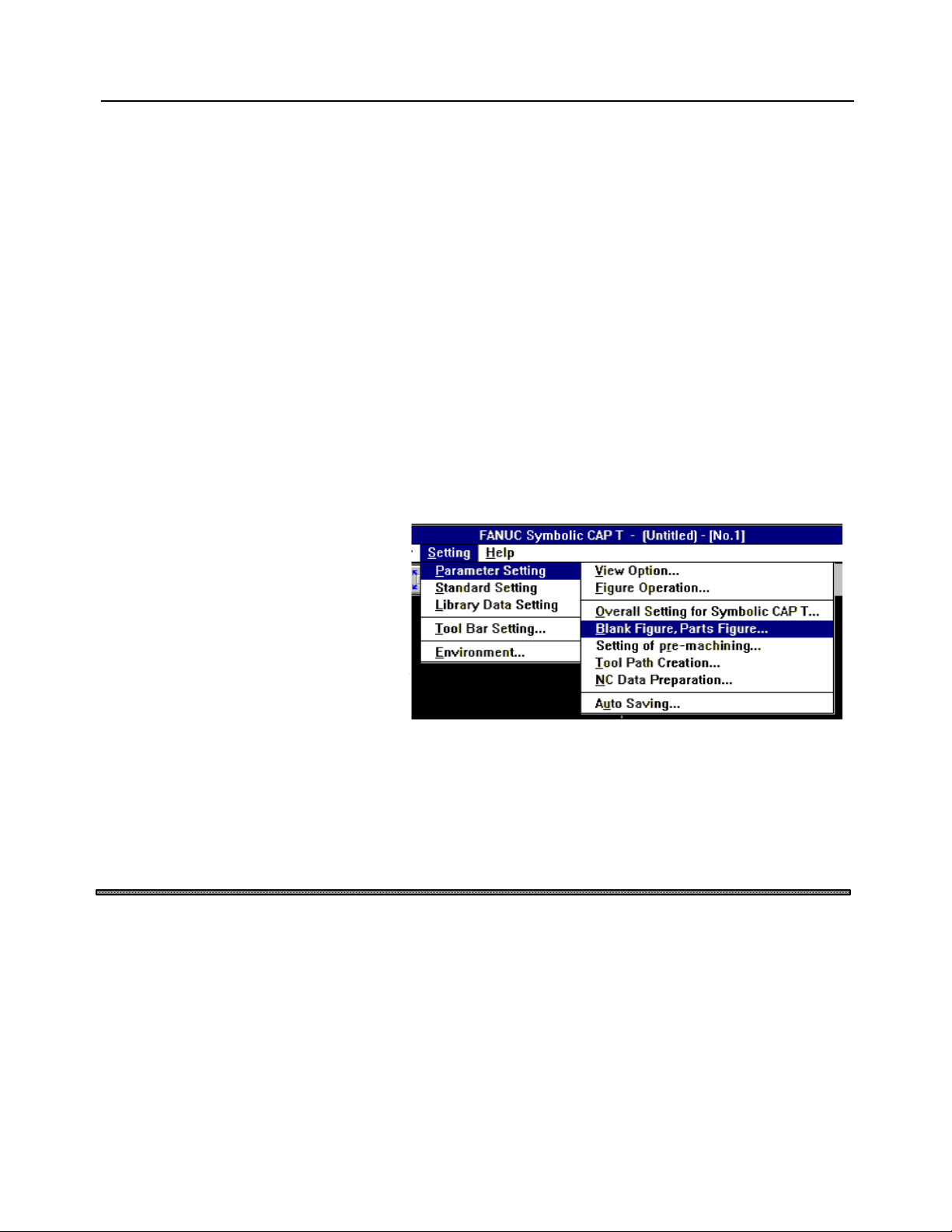
• Menus
When a command is to be selected from the menu bars, a right arrow (=>) is
used to link the menus in the sequence, as shown below:
“First menu => second menu => third menu”
Example) The menus shown below would be indicated as shown below:
“Setting => Parameter Setting => Blank Figure, Parts Figure”
Features of Symbolic CAP T
• Window examples
The windows shown in this document are merely examples. Note that the
window layout and file names used may vary depending on the equipment or
the resolution of the display unit you are using.
• Operation on Windows
Comfortable operating environment is afforded by Windows which provides
a de facto standard user interface.
Even inexperienced users can use the system by interactive operation using
graphical menus and a mouse.
• User-friendly operating procedure that is easy to use, even by
beginners
Symbolic CAP T is easy even for beginners to use, thanks to its support of
graphical menus (icons) and mouse-driven conversational processing. In
addition, it provides a wealth of help messages.
Page 11

PREFACE B-62824EN/02
p-6
• Operating procedure for experienced operators
Symbolic CAP T commands can be entered from the keyboard, enabling
experienced operators to operate the system quickly.
• Customizing functions
The user can improve the operability or add functions to suit the usage of
customers. Customizing to call frequently used functions by a simple
operation on tool bar is possible.
• One-click switching of the window
The window can be switched between that for machining definition and that
for figure creation simply by clicking a button. Therefore, even if a figure is
found to be missing during machining definition, figure input need not be
repeated from the very beginning.
• Symbolic figure input
Blank and parts figure can be entered using conventional symbolic figure
input based on arrows.
• Fully automatic process determination
An optimum machining type, a tool, a portion to be cut, and machining
conditions can be automatically selected simply by entering blank and part
figures. Even beginners can create machining programs quickly and easily.
• Machining simulation
Three-dimensional animated machining simulation and tool path drawing are
performed simultaneously.Animated machining simulation allows the
operator to actually observe the progress of machining. Tool path drawing
enables the operator to check the tool path generated by a machining
program in detail.
• Tool path editing function
The tool path editing function enables editing tool paths generated on
Symbolic CAP T as figure images, using a mouse.
It is possible to re-prepare NC data from edited tool paths.
Page 12

B-62824EN/02
c-1
Table of Contents
SAFETY PRECAUTIONS................................................................................................ s-1
GENERAL WARNINGS AND CAUTIONS RELATING TO USE WITH A CNC...............s-2
GENERAL WARNINGS AND CAUTIONS RELATING TO USE WITH A
PERSONAL COMPUTER................................................................................................s-3
PREFACE........................................................................................................................p-1
Checking the contents of the package.............................................................................................p-1
About this manual ........................................................................................................................... p-2
Notations......................................................................................................................................... p-4
Features of Symbolic CAP T...........................................................................................................p-5
1 SETUP............................................................................................................................ 1
1.1 Prior to Setting Up (Operating Environment) ................................................................................ 1
1.1.1 Prerequisites....................................................................................................................................................1
1.1.2 Other usable devices........................................................................................................................................2
1.2 Setting Up Symbolic CAP T ......................................................................................................... 3
1.2.1 About Setup .....................................................................................................................................................3
1.2.2 Setting up an optional module..........................................................................................................................6
1.2.3 Reinstalling Symbolic CAP T...........................................................................................................................8
1.2.4 About the protector (Only for use with a personal computer) ............................................................................8
2 BASIC OPERATION....................................................................................................... 9
2.1 Fundamentals .............................................................................................................................. 9
2.1.1 Starting Symbolic CAP T.................................................................................................................................9
2.1.2 Terminating Symbolic CAP T ..........................................................................................................................9
2.1.3 Reading the latest information about Symbolic CAP T .....................................................................................9
2.1.4 Other Symbolic CAP T icons............................................................................................................................9
2.2 Contents of Symbolic CAP T Window ........................................................................................ 11
2.2.1 Title bar.........................................................................................................................................................11
2.2.2 Side menu......................................................................................................................................................12
2.2.3 Menu bar.......................................................................................................................................................13
2.2.4 Tool bar.........................................................................................................................................................13
2.2.5 Drawing window............................................................................................................................................13
2.2.6 Prompt area ................................................................................................................................................... 14
2.2.7 Status window ............................................................................................................................................... 15
2.3 Basic Operation.......................................................................................................................... 16
2.3.1 Using the Help function to become familiar with the operating procedure......................................................................16
2.3.2 Confirming the version...................................................................................................................................16
2.3.3 Modifying the operation flow.........................................................................................................................17
2.4 Functions Provided by Side Menu.............................................................................................. 19
2.4.1 Programming mode........................................................................................................................................19
2.4.2 Figure creation mode .....................................................................................................................................19
2.5 Functions Provided by Menu Bar................................................................................................ 26
2.5.1 File menu ......................................................................................................................................................26
2.5.2 Modify menu ................................................................................................................................................. 27
Page 13

Table of Contents B-62824EN/02
c-2
2.5.3 Edit menu......................................................................................................................................................28
2.5.4 View menu ....................................................................................................................................................30
2.5.5 Auxiliary menu..............................................................................................................................................31
2.5.6 Setting menu..................................................................................................................................................32
2.5.7 Help menu.....................................................................................................................................................33
2.6 Functions Provided by the Tool Bar............................................................................................ 34
2.7 Flow of Operation ....................................................................................................................... 35
2.7.1 Overview of each function..............................................................................................................................35
2.7.2 Overview of data............................................................................................................................................36
2.8 Layers......................................................................................................................................... 38
2.8.1 About layers...................................................................................................................................................38
2.8.2 Major classification of layers..........................................................................................................................38
2.8.3 Figure creation layer setting...........................................................................................................................39
2.9 Drawing Format Setting.............................................................................................................. 40
3 PROGRAMMING EXAMPLE ........................................................................................ 41
3.1 Flow of Operation ....................................................................................................................... 41
3.1.1 Procedure.......................................................................................................................................................41
3.1.2 Explanation of each step ................................................................................................................................ 42
3.1.3 Example of operation.....................................................................................................................................43
4 BLANK FIGURE CREATION........................................................................................ 54
4.1 Blank Figure Creation................................................................................................................. 54
4.2 Special Figure............................................................................................................................ 56
4.3 Blank Figure Color/Line Type Modification ................................................................................. 58
5 PARTS FIGURE CREATION........................................................................................ 59
5.1 Turning Figure Creation.............................................................................................................. 59
5.2 Symbolic Input Method ............................................................................................................... 61
5.2.1 Entity selection..............................................................................................................................................61
5.2.2 Symbolic figure data input ............................................................................................................................. 62
5.2.3 Symbolic Figure data editing.......................................................................................................................... 78
5.2.4 Symbolic figure creation by figure reference................................................................................................... 80
6 PRE-MACHINING SETTING......................................................................................... 84
6.1 Selecting Tooling Data............................................................................................................... 85
6.2 Selecting an NC Machine File .................................................................................................... 86
6.3 Setting the Home Position.......................................................................................................... 87
6.4 Setting the Index Position........................................................................................................... 88
6.5 Setting the Chuck....................................................................................................................... 89
6.5.1 Setting items of the chuck..............................................................................................................................89
6.5.2 Chuck figure registration/edit window............................................................................................................91
7 MACHINING DEFINITION............................................................................................. 93
7.1 Machining Definition Window ..................................................................................................... 94
7.2 Selecting the Machining Type..................................................................................................... 95
7.3 Specifying the Cutting Area and Condition Data......................................................................... 97
7.3.1 Specifying the Cutting Area ........................................................................................................................... 97
Page 14

B-62824EN/02 Table of Contents
c-3
7.3.2 Location of the division point and the cutting area ........................................................................................101
7.3.3 Condition setting..........................................................................................................................................105
7.3.4 Specifying Another Area..............................................................................................................................107
7.4 Changing and Modifying the Machining Process........................................................................109
7.5 Defining New Machining Process ..............................................................................................111
7.6 Fully Automatic Determination ..................................................................................................112
8 NC DATA PREPARATION ......................................................................................... 115
8.1 Preparing and Displaying NC Data............................................................................................115
8.2 NC Data Preparation Window....................................................................................................116
8.3 Process Order Editing Window..................................................................................................119
8.4 NC Data Preparation Data Setting Window ...............................................................................121
8.5 Animation Window ....................................................................................................................122
8.6 Data Setting Window for Animated Simulation..........................................................................124
8.7 Writing NC Data to a Floppy Disk and Transferring NC Data to a Peripheral Device .................125
8.8 Printing NC Data and a Process Table ......................................................................................126
9 TOOL PATH EDITING................................................................................................ 127
9.1 Tool Path Editing.......................................................................................................................127
9.1.1 Tool paths subjected to editing .....................................................................................................................127
9.1.2 Unit of editing .............................................................................................................................................128
9.1.3 Coordinate system used for tool path editing ................................................................................................128
9.1.4 Editing......................................................................................................................................................... 128
9.2 Execution of Tool Path Editing ..................................................................................................129
9.3 Tool Path Editing Dialog Box.....................................................................................................130
9.3.1 Machining process list .................................................................................................................................130
9.3.2 Selecting a tool path for editing....................................................................................................................130
9.3.3 Deleting tool paths .......................................................................................................................................131
9.3.4 Terminating tool path editing.......................................................................................................................131
9.4 Editing Movement Entities.........................................................................................................132
9.4.1 Adding movement entities............................................................................................................................ 132
9.4.2 Erasing movement entities ........................................................................................................................... 133
9.4.3 Trimming/Extending movement entities .......................................................................................................133
9.4.4 Undoing/redoing editing...............................................................................................................................133
9.4.5 Specifying start entities ................................................................................................................................134
9.4.6 Checking tool paths for continuity................................................................................................................135
9.4.7 Listing entities.............................................................................................................................................136
9.4.8 Canceling movement entity editing...............................................................................................................136
9.4.9 Terminating movement entity editing...........................................................................................................137
10 SAVING AND LOADING FILE.................................................................................. 138
10.1 Saving a File...........................................................................................................................138
10.2 Loading a File..........................................................................................................................139
11 CREATING NEW PROGRAM................................................................................... 140
12 FIGURE CREATION................................................................................................. 141
12.1 Types of Figures......................................................................................................................141
12.2 Specifying a Radius, Distance, and Angle ...............................................................................142
Page 15

Table of Contents B-62824EN/02
c-4
12.3 Specifying Positions................................................................................................................143
12.4 Selecting Entities.....................................................................................................................145
12.5 Coordinate System..................................................................................................................147
12.5.1 World coordinate system............................................................................................................................147
12.5.2 Machining plane coordinate system............................................................................................................147
12.6 Modifying Figures by Extension/Trimming...............................................................................148
12.7 Copying Figures......................................................................................................................149
12.8 Creating Polygons...................................................................................................................155
12.9 Fitting Curve ...........................................................................................................................156
12.9.1 Creation method of a fitting curve .............................................................................................................. 156
12.9.2 Adjusting the creation method of a fitting curve..........................................................................................156
12.10 Offset....................................................................................................................................159
12.10.1 Outward offset for a corner....................................................................................................................... 159
12.10.2 Inward offset for a corner .........................................................................................................................160
13 CUTTING CONDITION DATA.................................................................................. 162
13.1 Overview.................................................................................................................................162
13.2 Functions ................................................................................................................................164
13.3 Starting of Editing Cutting Condition Data................................................................................165
13.4 Adding a Material Name..........................................................................................................166
13.5 Deleting a Material Name [Edit Cutting Condition Data]...........................................................168
13.6 Editing Cutting Condition Data.................................................................................................169
13.6.1 Modifying cutting condition data on a machining type basis........................................................................169
13.6.2 Adding cutting condition data..................................................................................................................... 170
13.6.3 Modifying cutting condition data................................................................................................................175
13.6.4 Deleting cutting condition data...................................................................................................................175
13.6.5 Changing the order of the tool types ........................................................................................................... 175
13.6.6 Deleting cutting condition data on a machining type basis ..........................................................................175
13.7 Calculating Method of the Machining Condition Data ...............................................................176
14 CUTTING CONDITION DATA UTILITY.................................................................... 179
14.1 Functions ................................................................................................................................179
14.2 Starting the Cutting Condition Data Utility................................................................................180
14.3 Selecting Utility Functions .......................................................................................................181
14.4 Outputting Cutting Condition Files...........................................................................................182
14.5 Inputting Cutting Condition Files..............................................................................................184
14.6 Changing Cutting Condition Files ............................................................................................186
14.7 Uniting Cutting Condition Files ................................................................................................189
15 TOOL DATA AND TOOLING DATA ........................................................................ 192
15.1 Overview.................................................................................................................................192
15.2 Functions ................................................................................................................................194
15.3 Starting of Tool Data/Tooling Data Editing...............................................................................195
15.4 Addition of Tooling Data..........................................................................................................196
15.5 Deleting a Tooling ...................................................................................................................198
15.6 Modification of the Tooling Data..............................................................................................199
15.6.1 Adding or inserting the tool data for a tool into the tooling data..................................................................199
15.6.2 Registering a new tool and adding or inserting the data into the tooling data............................................... 200
Page 16

B-62824EN/02 Table of Contents
c-5
15.6.3 Modifying tool registered in the tooling data ..............................................................................................202
15.6.4 Duplicating a tool in tooling data................................................................................................................202
15.6.5 Changing the order of the tools in the tooling data......................................................................................202
15.6.6 Deleting tooling from the tooling data ........................................................................................................203
15.6.7 Registering a new tool and adding or inserting tool data.............................................................................203
15.6.8 Modifying tool registered in the tool data ................................................................................................... 203
15.6.9 Duplicating the tool in the tool data............................................................................................................ 203
15.6.10 Changing the order of the tools in the tool data .........................................................................................204
15.6.11 Deleting tool from the tool data................................................................................................................204
15.6.12 Adding or deleting a tool material name only............................................................................................ 204
16 TOOL/TOOLING DATA UTILITY............................................................................. 205
16.1 Functions ................................................................................................................................205
16.2 Starting the Tool/Tooling Data Utility.......................................................................................206
16.3 Selecting Utility Functions .......................................................................................................207
16.4 Outputting Tool/Tooling Files...................................................................................................208
16.5 Inputting Tool/Tooling Files .....................................................................................................210
16.6 Changing Tooling Files ............................................................................................................212
17 NC MACHINE SETTING........................................................................................... 214
17.1 NC Machine File.....................................................................................................................214
17.2 Overview of NC Data Preparation Procedure ..........................................................................215
17.3 Modifying the NC Data Output Format.....................................................................................216
17.4 Machine Specifications............................................................................................................219
17.4.1 NC machine name......................................................................................................................................219
17.4.2 Home position/index position .....................................................................................................................219
17.4.3 Total number of axes/number of simultaneously controlled axes .................................................................219
17.4.4 Feedrate.....................................................................................................................................................220
17.4.5 Spindle speed.............................................................................................................................................220
17.4.6 Whether to use the ATC function ............................................................................................................... 220
17.5 CNC Specifications .................................................................................................................221
17.5.1 Address setting ..........................................................................................................................................221
17.5.2 G code ....................................................................................................................................................... 222
17.5.3 M code.......................................................................................................................................................222
17.5.4 Arbitrary character string ...........................................................................................................................223
17.5.5 Specifying required functions.....................................................................................................................223
17.6 NC Data Format......................................................................................................................225
17.6.1 Example of referencing NC data formats....................................................................................................225
17.6.2 Timing of NC data format reference...........................................................................................................226
17.7 Example of NC Data Output....................................................................................................239
17.8 NC Machine Setting Tool Operation ........................................................................................241
17.9 Customization .........................................................................................................................242
17.9.1 File configuration.......................................................................................................................................242
17.9.2 Modifying initial values ............................................................................................................................. 243
17.9.3 Modifying setting item names ....................................................................................................................244
17.9.4 Deleting setting items ................................................................................................................................245
17.9.5 Adding setting items .................................................................................................................................. 246
18 FILE TRANSFER...................................................................................................... 247
18.1 Function Outline......................................................................................................................247
Page 17

Table of Contents B-62824EN/02
c-6
18.1.1 Application software..................................................................................................................................247
18.1.2 Devices to which data can be transmitted ................................................................................................... 247
18.1.3 Data format that can be transmitted ............................................................................................................248
18.1.4 Transmission protocols...............................................................................................................................248
18.1.5 File operation functions.............................................................................................................................. 248
18.2 Activating the File Transmission Tool......................................................................................249
18.2.1 Activation using the Symbolic CAP T output function ................................................................................249
18.2.2 Activating only the File Transmission Tool ................................................................................................250
18.2.3 Activating the File Transmission Manager .................................................................................................250
18.3 File Transmission Tool Window ...............................................................................................251
18.3.1 Menus........................................................................................................................................................251
18.3.2 File specification areas...............................................................................................................................252
18.3.3 Buttons......................................................................................................................................................252
18.3.4 Operation guide .........................................................................................................................................252
18.4 Operating Procedure...............................................................................................................253
18.4.1 Selecting the device and setting the transmission conditions.......................................................................253
18.4.2 Specifying files .......................................................................................................................................... 253
18.4.3 Selecting a command .................................................................................................................................254
18.4.4 Changing the contents of the transmission operation...................................................................................254
18.4.5 Starting transmission..................................................................................................................................255
18.4.6 Checking the transmission status................................................................................................................255
18.4.7 Ending the transmission operation..............................................................................................................256
18.5 Outline of Processing for Each Function ..................................................................................257
18.5.1 Send ..........................................................................................................................................................257
18.5.2 Receive ......................................................................................................................................................257
18.5.3 Delete........................................................................................................................................................257
18.5.4 Clear.......................................................................................................................................................... 258
18.5.5 Rename......................................................................................................................................................258
18.5.6 Read-only and read/write ...........................................................................................................................258
18.5.7 Refresh......................................................................................................................................................259
18.6 Setting Transmission Conditions..............................................................................................260
18.6.1 Setting procedure.......................................................................................................................................260
18.6.2 Specifying the device and plotter ................................................................................................................263
18.6.3 Standard setting files..................................................................................................................................263
18.6.4 Setting the communication conditions ........................................................................................................264
18.6.5 Setting the transmission control conditions .................................................................................................265
18.6.6 Setting reception control conditions............................................................................................................266
18.7 Transmission Schedule Management......................................................................................268
18.7.1 Contents of the window.............................................................................................................................. 268
18.7.2 Changing the schedule ...............................................................................................................................269
18.7.3 Exiting the File Transmission Manager......................................................................................................270
18.8 Example Transmission Procedures .........................................................................................271
18.8.1 Transmission to and from the CNC ............................................................................................................271
19 PLOTTING................................................................................................................ 272
19.1 Setting Up a Plotter.................................................................................................................272
19.2 Procedures..............................................................................................................................274
20 CAD DATA INPUT/OUTPUT.................................................................................... 277
20.1 CAD Data Input/Output............................................................................................................277
Page 18

B-62824EN/02 Table of Contents
c-7
20.1.1 CAD data...................................................................................................................................................277
20.1.2 Handling of CAD data by this system.........................................................................................................278
20.2 DXF File Input/Output..............................................................................................................279
20.2.1 Overview of DXF....................................................................................................................................... 279
20.2.2 DXF file input ...........................................................................................................................................282
20.2.3 Setting the input conversion method ...........................................................................................................284
20.2.4 DXF file output.......................................................................................................................................... 289
20.2.5 Setting the output conversion method.........................................................................................................291
20.3 Handling CAD Data Efficiently .................................................................................................295
20.4 Conversion Specifications for DXF File Input/Output...............................................................296
20.4.1 DXF input conversion specifications ..........................................................................................................296
20.4.2 DXF output conversion specifications.........................................................................................................298
21 FAPT LANGUAGE FIGURE INPUT ......................................................................... 301
21.1 Overview.................................................................................................................................301
21.1.1 Figure types that can be input..................................................................................................................... 301
21.1.2 FAPT statement types that can be input......................................................................................................301
21.2 Operation................................................................................................................................302
21.2.1 Start-up...................................................................................................................................................... 302
21.2.2 Part program selection................................................................................................................................302
21.2.3 FAPT language figure input .......................................................................................................................303
21.2.4 Settings related to the FAPT language figure input function .......................................................................304
21.2.5 Displaying the progress of input processing................................................................................................305
21.2.6 Displaying input information......................................................................................................................306
21.3 Cautions and Restrictions........................................................................................................307
22 DIMENSION MEASUREMENT ................................................................................. 308
22.1 Dimension Measurement Function ..........................................................................................308
22.2 Measurable Dimensional Values..............................................................................................309
22.3 Activating Dimension Measurement ........................................................................................310
22.4 Measuring Coordinates............................................................................................................311
22.5 Distance between Two Points..................................................................................................313
22.6 Distance between Point and Entity ..........................................................................................314
22.7 Circle/Arc Radius.....................................................................................................................315
22.8 Angles Formed by Two Lines ..................................................................................................316
22.9 Displaying Measurements........................................................................................................317
22.10 Cautions................................................................................................................................318
23 STANDARD SETTING.............................................................................................. 319
23.1 Standard Setting for Blank Figure and Parts Figure.................................................................319
23.2 Standard Setting for NC Data Preparation...............................................................................320
24 PARAMETER SETTING........................................................................................... 321
24.1 Parameter Setting for View......................................................................................................321
24.2 Parameter Setting for Figure Operation...................................................................................322
24.3 Parameter Setting for Overall Setting of Symbolic CAP T.......................................................324
24.4 Parameter Setting for Blank Figure and Part Figure ................................................................324
24.5 Parameter Setting for Pre-Machining Setting...........................................................................325
Page 19

Table of Contents B-62824EN/02
c-8
24.6 Parameter Setting for Machining Definition .............................................................................325
24.7 Parameter Setting for Machining Condition Automatic Decision ..............................................326
24.8 Parameter Setting for Tool Path Creation................................................................................331
24.9 Parameter Setting for NC Data Preparation .............................................................................332
24.10 Parameter Setting for Auto Saving........................................................................................333
25 TOOL BAR SETTING............................................................................................... 334
25.1 Tool Bar Setting ......................................................................................................................334
25.1.1 Storing the tool bar definition file...............................................................................................................334
25.1.2 Creating icons............................................................................................................................................ 334
25.1.3 Displaying the Tool Bar Setting window ....................................................................................................334
25.1.4 Registering menu items..............................................................................................................................335
25.1.5 Deleting buttons/spaces.............................................................................................................................. 335
25.1.6 Inserting spaces.......................................................................................................................................... 335
25.1.7 Changing icons ..........................................................................................................................................335
25.1.8 Saving settings/returning to the normal state ..............................................................................................336
25.1.9 Discarding the settings/returning to the normal state ..................................................................................336
26 TROUBLESHOOTING.............................................................................................. 337
26.1 Before Trouble Occurs ............................................................................................................337
26.2 If Trouble Occurs.....................................................................................................................338
26.3 Error Messages.......................................................................................................................339
26.3.1 Abbreviations of functions..........................................................................................................................340
26.3.2 Messages related to blank and parts figure preparation ...............................................................................341
26.3.3 Messages related to pre-machining settings................................................................................................345
26.3.4 Messages concerning machining surface setting..........................................................................................347
26.3.5 Messages related to machining definition...................................................................................................347
26.3.6 Messages related to NC data preparation....................................................................................................351
26.3.7 Messages concerning the milling library.....................................................................................................363
26.3.8 Messages related to loading part files .........................................................................................................366
26.3.9 Messages related to cutting condition setting ..............................................................................................369
26.3.10 Messages related to tool and tooling data..................................................................................................375
26.3.11 Other messages........................................................................................................................................379
27 APPENDIX................................................................................................................ 382
27.1 Function Codes.......................................................................................................................382
27.1.1 NC data format setting function codes (special functions)........................................................................... 382
27.1.2 NC data format setting function codes (move command words) ..................................................................382
27.1.3 NC data format setting function codes (G codes).................................................................................... 385
27.1.4 NC data format setting function codes (integer words)................................................................................389
27.1.5 NC data format setting function codes (special codes) ................................................................................389
27.1.6 NC data format setting function codes (M codes)........................................................................................ 390
27.1.7 NC data format setting function codes (S codes)......................................................................................... 391
27.1.8 NC data format setting function codes (T codes).........................................................................................391
27.1.9 NC data format setting function codes (outputting arbitrary character strings).............................................391
27.1.10 NC data format setting function codes (modal clearing)............................................................................392
27.2 Pre/Postprocessor Macro Syntax.............................................................................................393
27.2.1 General ......................................................................................................................................................393
27.2.2 Components............................................................................................................................................... 393
27.2.3 Structure.................................................................................................................................................... 395
Page 20

B-62824EN/02 Table of Contents
c-9
27.2.4 Declare statement ......................................................................................................................................397
27.2.5 Expression and assignment ........................................................................................................................398
27.2.6 Control statement.......................................................................................................................................400
27.2.7 Procedure statement................................................................................................................................... 402
27.2.8 EL statement..............................................................................................................................................405
27.2.9 Preprocessor pseudo instruction .................................................................................................................405
27.2.10 Restrictions ..............................................................................................................................................406
Page 21

B-62824EN/02 1. SETUP
-1-
1 SETUP
1.1 Prior to Setting Up (Operating Environment)
1.1.1 Prerequisites
The following operating environment is needed to run Symbolic CAP T.
• Computer
FANUC open CNC (with HSSB personal computer connection), or personal
computer
CPU: i486TMDX or higher (math co-processor required)
Memory: 12 MB or more
Floppy disk: 3.5-inch, 1.44MB
Hard disk: Total capacity of 80 MB or more (20 MB or more of
dedicated area and 32 MB or more of swap file area)
• Display unit
Resolution: 640 × 480 dots or higher
Color: 256 colors
• Keyboard and mouse
(Essential for use with a personal computer)
• Parallel-interface printer cable
(Essential for use with a personal computer)
• Microsoft Windows Version 3.1 or higher, set to enhanced
mode
NOTE
For use with a personal computer, printer cable is required to
connect the protector.
Page 22

1. SETUP B-62824EN/02
-2-
1.1.2 Other usable devices
• Printer
Windows printer driver
• Plotter
Only for use with a personal computer
NOTE
The plotter having the command system of HP-GL is supported. HPGL2 or other command system is not supported.
Page 23

B-62824EN/02 1. SETUP
-3-
1.2 Setting Up Symbolic CAP T
1.2.1 About Setup
Start with the setup of the Symbolic CAP T basic module. (When the basic
module has already been set up, and only the optional module is to be set up,
no additional setup is required for the basic module.)
• Preparation
(1) First, create a directory on the hard disk to which the Symbolic CAP
T system program will be stored. (Example: C:\CAP T)
NOTE
Do not set up Symbolic CAP T in the root directory (\).
CAUTION
If other programs, such as FANUC PC FAPT, have already been set
up, do not set up Symbolic CAP T in the same directory as these
programs.
If the same directory is used, both programs may malfunction.
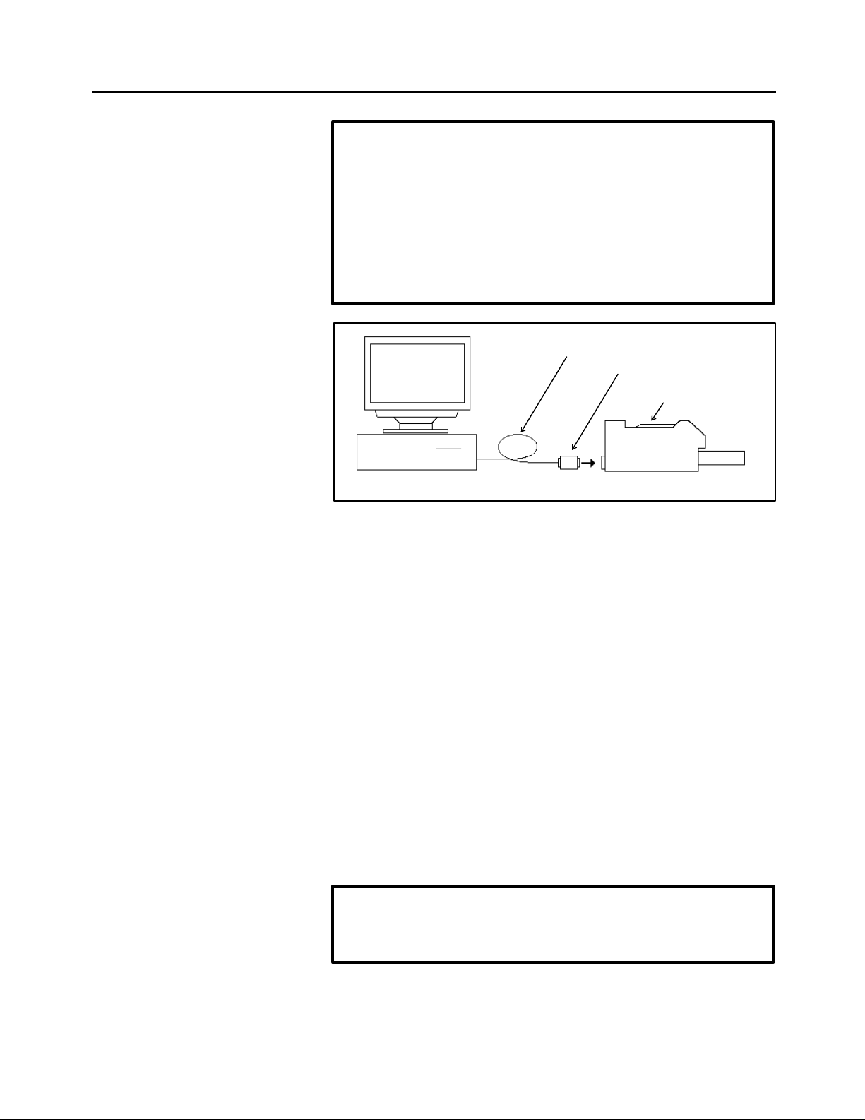
(2) After making sure that the computer and printer are switched off,
attach the protector for the Symbolic CAP T basic module.
NOTE
The open CNC architecture does not require this procedure.
CAUTION
The computer and printer must be switched off while the protector is
being attached.
If the protector is attached or detached while the computer and
printer are switched on, the computer, printer, or protector may be
damaged.
Page 24
1. SETUP B-62824EN/02
-4-
NOTE
If other programs, such as FANUC PC FAPT, have already been set
up, their protectors can be assembled into the Symbolic CAP T basic
module protector. The protectors to be assembled into the Symbolic
CAP T basic module protector must be attached before installing
Super CAP T. They can be removed after a setting has been made
such that they are assembled into the Symbolic CAP T protector.
They can be connected in any order.
Printer Cable
Protector
Printer
(3) Switch on the computer and start Windows.
• Setup procedure
(1) Insert the basic module floppy disk (labeled FANUC Symbolic CAP
T Basic module Vx Disk#1) into the floppy drive (where x in Vx is a
numeral).
(2) Select File => Run menu of Program Manager for Windows 3.1, or
select Start => Run menu of Task Bar for Windows 95.
(3) Key in drive-name:\SETUP (where drive-name is the name of the
3.5-inch floppy drive into which the floppy disk has been inserted).
Then, click OK.
(4) When the installation process prompts you to specify where Symbolic
CAP T is to be installed, key in the name of the directory where
Symbolic CAP T is to be installed, then press the Continue button.
(5) When the installation process prompts you to specify the data file to
be set up, select a data file, then click Continue.
NOTE
When setting up Symbolic CAP T for the first time, all data files must
be registered.
(6) Installing the sysytem files to the hard disk begins. As the
installation progress, you will be prompted to insert the next floppy
disk. Insert the next disk, then click OK. Repeat this until all of the
floppy disks have been processed.
Page 25

B-62824EN/02 1. SETUP
-5-
(7) When the installation process prompts you to specify the directory
into which each type of data is to be stored, change the directory
name as required, then click OK.
NOTE
When it is necessary to change a directory name, select the desired
data type from the list, then click Change. After selecting or keying in
a new drive name and directory name, click OK.
Even once setup has been completed, the data directory can be
changed by selecting “Setting => Environment” from the Symbolic
CAP T menu.
(8) A prompt is displayed to inquire whether the optional module is to be
set up. Click the Yes or No button.
NOTE
When you click the Yes button, the prompt as provided in step (4) is
displayed. Insert the optional module floppy disk labeled Disk#1,
reenter the installation destination directory name, then select the
Continue button. (The optional module must be installed in the same
directory as for the basic module.) For details, see Section 1.2.2,
“Setting up an optional module.”
(9) Finally, a prompt appears asking whether you want to assemble the
protectors of other softwares, such as FANUC PC FAPT, into the
protector of the Symbolic CAP T basic module. Click Yes or No, as
appropriate. If the protectors of other programs have not yet been
attached, click No.
NOTE
This question does not appear in the open CNC.
Clicking Yes makes it possible to use other softwares simply by
gathering their protector to the Symbolic CAP T basic module
protector. After keying in the specification number of the software
whose protector you want to gather into the Symbolic CAP T
protector, click Gather two protect keys into one protector. (The
specification number of the software appears on the floppy disk from
which the software is installed.)
When No is clicked, the protectors must be attached individually.
(10) When a message indicating the normal completion of setup appears,
click OK.
(11) Upon the completion of setup, confirm that FANUC Symbolic CAP T
Page 26
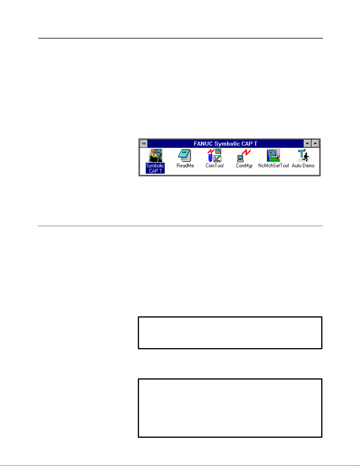
1. SETUP B-62824EN/02
-6-
group window has been added to Program Manager, together with an
icon for Symbolic CAP T.
(12) When a message indicating the normal completion of setup appears,
click OK.
(13) Upon the completion of setup, confirm that the FANUC Symbolic
CAP T group window has been added to the Program Manager,
together with an icon for Symbolic CAP T.
• Icon registered
Prompts and/or messages not described above may appear depending on the
specific installation. In such cases, proceed as indicated on the window.
1.2.2 Setting up an optional module
When using an optional module, set it up once setup of the basic module has
been completed. The procedure for setting up a typical optional module is
described below. Note that some optional modules require the application of
special procedures or precautions. Therefore, always refer to the
corresponding operator's manual.
• Preparation
(1) Check the name of the directory where the basic module has been
installed.
NOTE
Optional modules must be stored into the same directory as that
where the basic module has been installed.
(2) After making sure that the computer and printer are switched off,
attach the protectors for the basic module and optional module.
CAUTION
The computer and printer must be switched off while the protectors
are being attached.
If the protector is attached or detached while the computer and
printer are switched on, the computer, printer, or protector may be
damaged.
Page 27
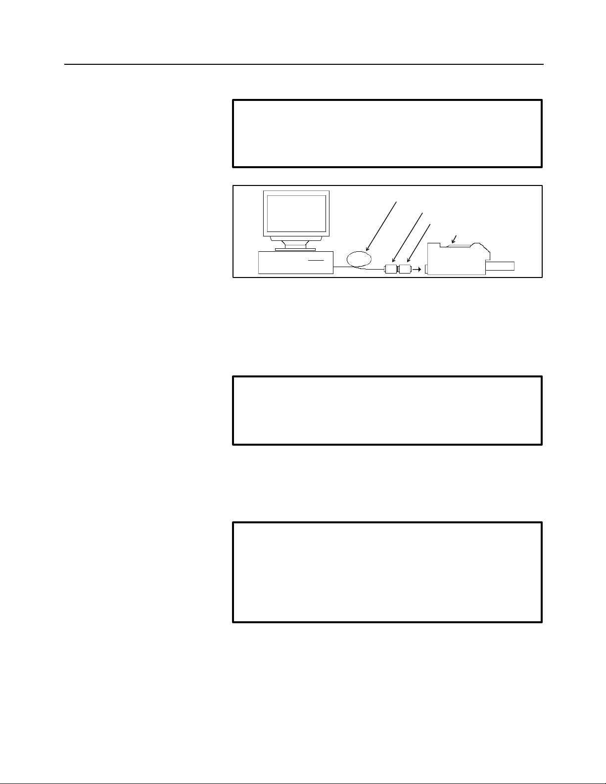
B-62824EN/02 1. SETUP
-7-
NOTE
If two or more optional modules are to be set up, the protectors for
all those modules can be attached at this time. Protectors can be
connected in series, in any order.
Printer Cable
Protector for Basic module
Protector for Option module
Printer
(3) Switch on the computer and start Windows.
• Setup procedure
(1) Perform setup in the same way as described in steps (1) to (7) for
setting up the basic module.
NOTE
Insert the floppy disk labeled Disk#1 for the module to be set up.
As the installation destination directory, specify the directory where
the basic module was installed.
(2) Upon the normal completion of setup, a prompt appears asking
whether the protectors for the basic and optional modules are to be
assembled into a single protector. Click Yes or No.
NOTE
Clicking Yes makes it possible to use Symbolic CAP T without
attaching the protectors for the optional modules.
When No is clicked, the protectors for the basic module and each of
the optional modules must be attached in series to enable the use of
Symbolic CAP T.
Prompts and/or messages other than those described above may appear
depending on the specific installation. In such cases, proceed as directed by
the prompt.
Page 28

1. SETUP B-62824EN/02
-8-
1.2.3 Reinstalling Symbolic CAP T
When reinstalling Symbolic CAP T in a directory where Symbolic CAP T has
already been set up, you can select whether to register the data files again.
When you want to use the existing data, do not register the corresponding
data when you are prompted to specify the data file to be set up.
When you want to reregister a data file, if the corresponding data file already
exists in the target directory, you will be prompted to specify whether the
previous data file is to be backed up. Click Yes or No, as required.
NOTE
When Yes is selected, the existing data is backed up to the BAK
subdirectory under the Symbolic CAP T directory. The Symbolic CAP T
directory will be rewritten with the standard data. If necessary, however,
the previous data can be restored from the BAK subdirectory.
When No is selected, the existing data is overwritten with the standard
data.
1.2.4 About the protector (Only for use with a personal computer)
The protector must be kept attached to enable the setup and use of Symbolic
CAP T. If it is detached, Symbolic CAP T will fail to run normally.
CAUTION
Both the computer and printer must be switched off before
attempting to either attach or disconnect the protector.
If the protector is attached or detached while the computer and printer are
switched on, the computer, printer, or protector may be damaged.
The protectors for other softwares can be gathered into the protector of the
Symbolic CAP T basic module. It is not possible to assemble the protector
of the Symbolic CAP T basic module into that of any other software.
If the protectors of other softwares are gathered into the Symbolic CAP T
protector, the user need no longer be concerned with the other protectors as
part of daily operation. These softwares can be made usable simply by
attaching the Symbolic CAP T protector. Note that the individual protectors
are required when the corresponding softwares are upgraded. So, they
should be kept in a safe place.
If the protectors are not gathered into the Symbolic CAP T protector, they
must be attached individually. They can be attached in any sequence.
Page 29
B-62824EN/02 2. BASIC OPERATION
-9-
2 BASIC OPERATION
2.1 Fundamentals
2.1.1 Starting Symbolic CAP T
Double-click the Symbolic CAP T icon.
2.1.2 Terminating Symbolic CAP T
Select File => Exit from the Symbolic CAP T menu.
2.1.3 Reading the latest information about Symbolic CAP T
Double-click the Read Me file icon. The Read Me file contains information
relating to Symbolic CAP T that users should be aware of, together with
information specific to the installed version. The information in the Read
Me file does not appear in the operator's manual. It is imperative, therefore,
that the user read the contents of this file.
2.1.4 Other Symbolic CAP T icons
There are several other executable icons for Symbolic CAP T. These
correspond to the File Transmission Tool, File Transmission Manager, NC
Machine Setting Tool, and Auto Demo.
Page 30

2. BASIC OPERATION B-62824EN/02
-10-
The File Transmission Tool enables NC data exchange with an external
device via a serial port. The File Transmission Manager is an application
that manages the transmission schedule and performs the actual
communication. Usually, it is not used independently.
The NC Machine Setting Tool is used to edit the contents of the
management file that governs the output format of NC data. Using these
tools together enables Symbolic CAP T to support a range of CNC units.
Auto Demo is an application that introduces the major functions of Symbolic
CAP T.
Page 31
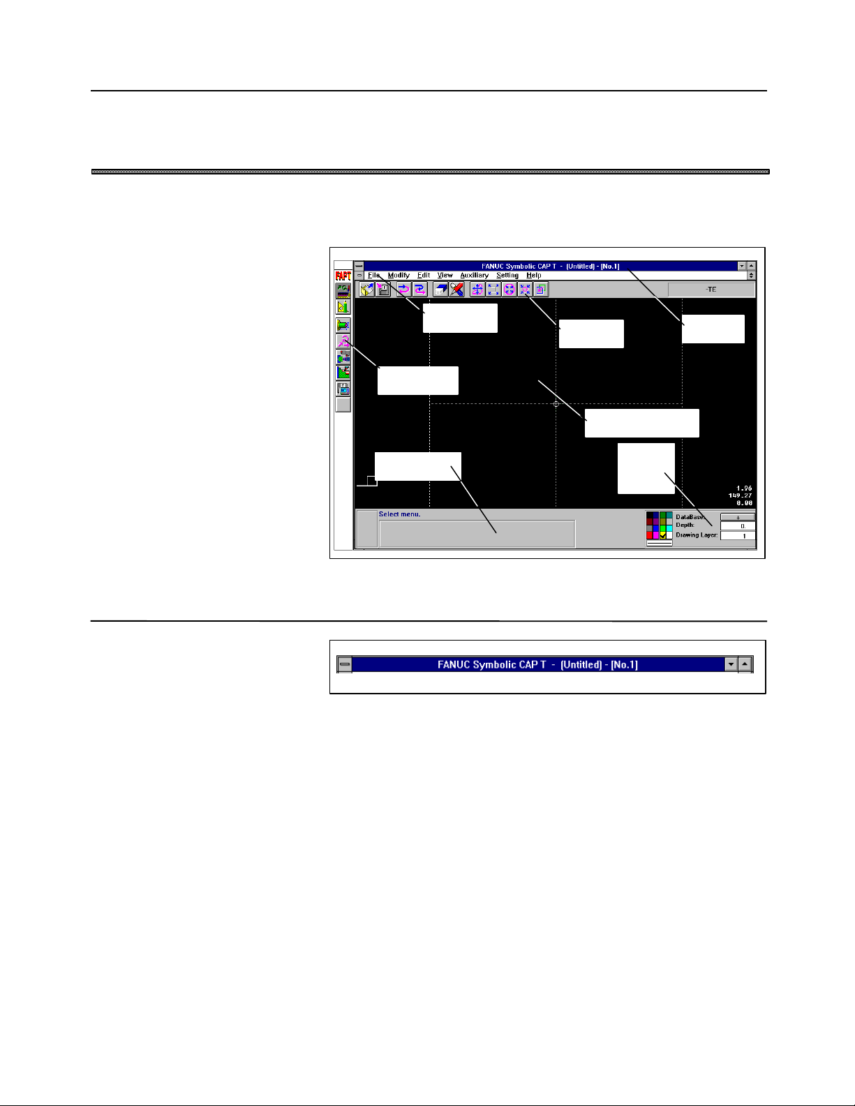
B-62824EN/02 2. BASIC OPERATION
-11-
2.2 Contents of Symbolic CAP T Window
This section describes the Symbolic CAP T windows, using, as an example,
the first window to appear after Symbolic CAP T becomes operable.
2.2.1 Title bar
Menu bar
Side menu
Prompt area
Tool bar
Drawing window
Title bar
Status
window
The title bar usually displays the name of the file being processed. If the file
has not yet been saved, Untitled is displayed.
Page 32

2. BASIC OPERATION B-62824EN/02
-12-
2.2.2 Side menu
Programming mode
Side menus contain icons corresponding to the major commands related to
programming and figure preparation.
The side menus are configured in a hierarchy.
Figure creation
mode
• Primary menu
Enables the selection of either programming or figure preparation mode.
• Secondary menu
When programming mode is selected, the main menu for programming
appears. When figure preparation mode is selected, the main menu for figure
preparation appears.
• Tertiary menu
A submenu corresponding to each figure appears only in figure preparation
mode.
Page 33

B-62824EN/02 2. BASIC OPERATION
-13-
2.2.3 Menu bar
Commands to be executed can be selected from the menu bar. Command
execution can be nested up to about 20 levels.
• File menu
Provides the functions used to manipulate files.
• Modify menu
Provides the functions used to modify individual figure entities.
• Edit menu
Provides the functions used to edit two or more figures at one time.
• View menu
Provides the functions used to display the drawing windows.
• Auxiliary menu
Provides auxiliary functions, such as those for setting drawing
formats and confirming entity information.
• Setting menu
Provides functions for setting parameters, such as machining
conditions, tool data, and standard values.
• Help menu
Provides functions that help explain the use of Symbolic CAP T.
2.2.4 Tool bar
Those functions that are used most frequently are also provided as icons, so
that processing can be simplified. Moreover, the tool bar can be customized
as necessary.
2.2.5 Drawing window
The drawing window displays information such as blank figure, parts figure,
those figures prepared in figure preparation mode, and tool paths.
When using the mouse to specify a position or select an entity in this
window, simply click the corresponding item directly.
Page 34

2. BASIC OPERATION B-62824EN/02
-14-
2.2.6 Prompt area
Key entry panel
Mode switch box
Position specification panel
Entity selection panel
Interrupt release button
In the prompt area, the user can enter responses to prompts output by the
current processing. System messages also appear in this area.
The prompt area may contain the following entities, depending on the type
of the prompt and the particular installation.
(a) Prompt back button ( button)
(b) Interrupt release button (ESC button)
(c) Mode switch box
(d) Key entry panel
(e) Position specification panel
(f) Entity selection panel
(g) Other panels as required
Prompt back button
Page 35

B-62824EN/02 2. BASIC OPERATION
-15-
2.2.7 Status window
The status window displays the current status of an entity being prepared,
such as color, line type, and layer No. The status of an entity can be
modified directly using the status window.
The status window contains the following items.
(a) Color setting button
(b) Line type setting button
(c) Figure search direction switch button
(d) Machining plane depth entry field
(e) Drawing layer No. entry field
When the Symbolic CAP T window is small, or if the display unit supports
only a low resolution, the status window may not appear. In such a case,
access the equivalent function on the menu bar (Auxiliary => Set Current
Attributes).
Page 36

2. BASIC OPERATION B-62824EN/02
-16-
2.3 Basic Operation
2.3.1 Using the Help function to become familiar with the operating procedure
Users can use the Help function to help them become familiar with the
operating procedure of Symbolic CAP T. Whenever the user is unsure of
how to proceed, accessing the Help function will provide guidance on the
correct procedure. This function provides information that does not appear
in the operator's manual.
Whenever the Help button appears in a window, double-clicking the button
will provide help relating to that window. Whenever there is no Help
button, help can be displayed by pressing the F1 key or by selecting the Help
menu from the menu bar.
The help menu contains the following submenus.
• Contents
This submenu enables the table of contents to be searched for topics
related to Symbolic CAP T.
• Search for Help on
This submenu enables a search to be made for topics related to
Symbolic CAP T according to a specified keyword. Selecting this
submenu causes a list of keywords that can be used for a search to
appear.
• How to Use Help
This submenu explains how to use the help function.
2.3.2 Confirming the version
When it is necessary to confirm the installed version of Symbolic CAP T,
such as when performing maintenance, select “Help => About Symbolic
CAP T” from the menu bar. The version of Symbolic CAP T and
information relating to the computer on which it is running will be
displayed, as shown below.
Page 37

B-62824EN/02 2. BASIC OPERATION
-17-
2.3.3 Modifying the operation flow
Symbolic CAP T commands are executed by selecting from side menus or
menu bars. Usually, a conversational window or a string of prompts appear.
Operation is performed by responding to the displayed messages or prompts.
This section explains how to abandon the execution of one command in
favor of another, as well as how to correct operator errors.
• Abandoning one command and executing another
Using the side menu, it is always possible to switch the command
being executed. Clicking an icon halts execution of the current
command and starts execution of the command corresponding to the
clicked icon.
Whenever it is not possible to click an icon in a side menu, click a
button such as OK, Cancel, Close, or Exit in the prompt area or in
any current conversational window, then try to click the desired icon
again.
• Interrupt by another command
The commands available on a menu bar or tool bar are executed like
interrupts. While a command is being executed, if another command
is selected from a menu bar or tool bar, the current command is
temporarily suspended while the newly selected command is
executed. Upon completion of the newly selected command,
execution of the original command is resumed from the point at
which processing was suspended.
Page 38

2. BASIC OPERATION B-62824EN/02
-18-
• Exiting an interrupt
Whenever a command is selected from a menu bar or tool bar, the
ESC button appears in the prompt area. The command currently
being executed can be terminated by clicking the ESC button or
pressing the ESC key.
Example) This method can be used, for example, to terminate an
edit or modify command that is repeatedly executed for two or
more figures, such as figure copy or Trim/Extend.
Command interrupts can be nested up to about 20 levels. Within this
limit, commands can be interrupted by others without terminating the
original commands.
When an icon on a side menu is clicked, all interrupting commands
are terminated automatically, and the newly selected command is
executed, even if the user does not intend to terminate those
commands.
• Returning to the previous prompt
If the current command displays more than one prompt area, clicking
the button in a prompt area or pressing the CTRL-BS keys returns
you back to the previous prompt area (if any).
Example) This function can be used with the command used to
define a straight line passing through two points. When you are
prompted to enter the second point after entering the first point,
you may decide that you want to respecify the first point. In such
a case, use this function.
Page 39

B-62824EN/02 2. BASIC OPERATION
-19-
2.4 Functions Provided by Side Menu
2.4.1 Programming mode
The programming mode side menu provides the following functions.
Icon Function
......................................Blank figure creation
......................................Parts figure creation
......................................Pre-machining setting
......................................Machining definition
......................................NC data preparation
.......................................Tool path editing
2.4.2 Figure creation mode
The figure creation mode side menu enables the generation of the following
figure entities.
Icon Function
Point and plural points creation
............................Single point
• Start or end point of an entity
• Intersection/point of
tangency between two entities
• Mid-point of an entity
• Center of a circle/arc entity
• Existing point
• Grid point
• Free point
Page 40

2. BASIC OPERATION B-62824EN/02
-20-
............................Linear plural points (with intervals specified)
............................Linear plural points (with a number of
divisions specified)
............................Circular plural points (with intervals
specified for the arc section)
............................Circular plural points (with the number of
divisions specified for the arc section)
............................Circular plural points (with the number of
divisions specified for the entire
circumference)
............................Rectangular plural points
............................Grid plural points
............................Random plural points
.................Add a point to random plural points
.................Insert a point into random plural points
.................Move a point among random plural points
.................Delete a point from random plural points
.................Determine random plural points
.................Select plural points as the target of operation
............................Plural points as nodes of a fitting curve
Page 41

B-62824EN/02 2. BASIC OPERATION
-21-
Icon Function
Straight line creation
............................Horizontal line
............................Vertical line
............................Horizontal and vertical lines
............................Straight line passing through a specified
point and having inclination of specified
degree.
............................Straight line tangential to a specified circle
and having inclination of specified degree.
............................Straight line passing through two specified
points
............................Straight line perpendicular bisector of a line
segment between two specified points
............................Straight line passing through a specified
point and parallel to a specified straight line
............................Straight line passing through a specified
point and perpendicular to a specified
straight line
............................Straight line passing through a specified
point and tangential to a specified circle
............................Straight line tangential to two specified
circles
............................Straight line having a distance d from a
specified straight line
............................Straight line bisecting an angle between two
specified straight lines
Page 42
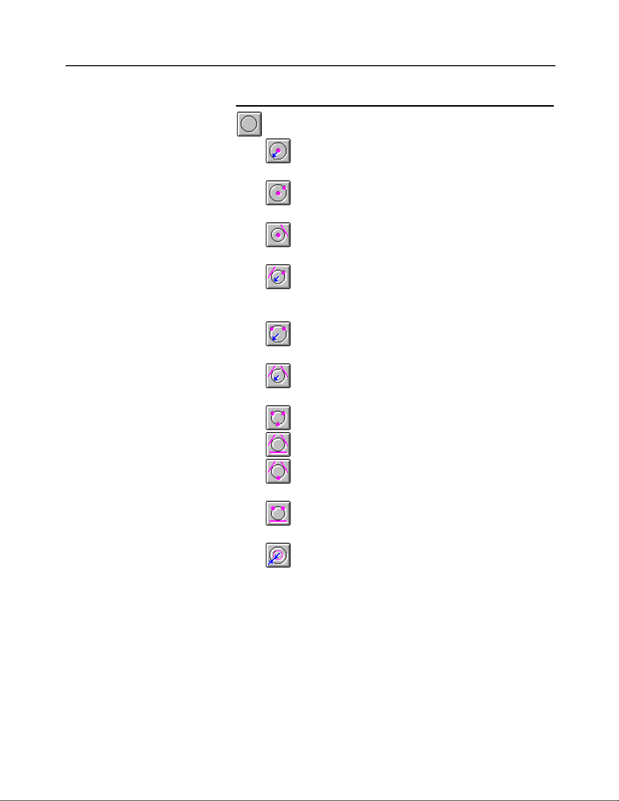
2. BASIC OPERATION B-62824EN/02
-22-
Icon Function
Circle creation
............................Circle having a specified point as its center
and radius r
............................Circle having a specified point as its center
and passing through a specified point
............................Circle having a specified point as its center
and tangential to a specified entity
............................Circle of radius r, passing through a
specified point, and tangential to a specified
entity
............................Circle of radius r and passing through two
specified points
............................Circle of radius r and tangential to two
specified entities
............................Circle passing through three specified points
............................Circle tangential to three specified entities
............................Circle passing through a specified point and
tangential to two specified entities
............................Circle passing through two specified points
and tangential to a specified entity
............................Circle for which the difference in radius
between the circle and a specified circle/arc
is specified value
Page 43
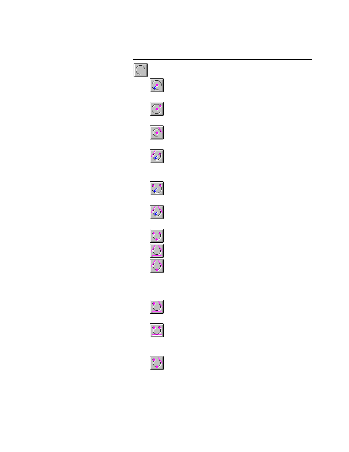
B-62824EN/02 2. BASIC OPERATION
-23-
Icon Function
Arc creation
............................Arc having a specified point as its center and
specified radius
............................Arc having a specified point as its center and
passing through a specified point
............................Arc having a specified point as its center and
tangential to a specified entity
............................Arc of specified radius, passing through a
specified point, and tangential to a specified
entity
............................Arc of specified radius and passing through
two specified points
............................Arc of specified radius and tangential to two
specified entities
............................Arc passing through three specified points
............................Arc tangential to three specified entities
............................Arc tangential to a specified entity at the
start point and another specified entity at the
end point, and passing through a specified
point
............................Arc starting at a specified point and
tangential to two specified entities
............................Arc starting at a specified point, ending at
another specified point, and tangential to a
specified entity
............................Arc starting at a specified point, passing
through another specified point, and
tangential to a specified entity
Page 44

2. BASIC OPERATION B-62824EN/02
-24-
............................Arc whose radius differs from the radius of
another arc by d
............................Arc whose radius differs from the radius of a
circle by d
Icon Function
Rectangle creation
............................Rectangle defined by diagonal two points
............................Rectangle having the specified horizontal
and vertical widths, and inclination of
specified degree
Icon Function
Polyline/polygon creation
............................Line segment starting at a specified point
and ending at another specified point
............................Arc tangential to a previous entity at the start
point
............................Arc passing through a specified point
............................Arc tangential to a specified entity
............................Arc of specified radius and drawn
counterclockwise
............................Arc of specified radius and drawn clockwise
............................Determine as a polyline
............................Determine as a polygon (by closing the start
and end points)
............................Create a polyline/polygon along other
entities (trace mode)
Page 45

B-62824EN/02 2. BASIC OPERATION
-25-
............................Cut a line segment/arc at an intersection
with another entity and determine as a
polyline
............................Cut a line segment/arc at an arbitrary point
and determine as a polyline
............................Select a polyline/polygon as a target of
operation
............................Connect a polyline/polygon to another entity
Icon Function
Fitting curve creation
............................Node addition
............................Node insertion
............................Node movement
............................Node deletion
............................Open fitting curve creation
............................Closed fitting curve creation
............................Select a fitting curve as a target of operation
Page 46

2. BASIC OPERATION B-62824EN/02
-26-
2.5 Functions Provided by Menu Bar
2.5.1 File menu
Menu item Function
• New Clears the figure and machining
specification data currently being created and
creates a new figure and machining
specification data.
When the New command is chosen, the data
of the figure and the machining definition
data made till then can be preserved.
• Open Reads a figure and machining data from a
file.
When the Open command is chosen, the data
of the figure and the machining definition
data made till then can be preserved.
• Save Saves the figure and machining data
currently being created to a file.
Former file is overwritten.
• Save As Specifies a file name and saves the figure
and machining data currently being created
to the specified file.
• Clear Machining Data Clears the machining data currently defined
and defines new machining data.
When the Clear Machining data command is
chosen, the data of the figure and the
machining definition data made till then can
be preserved.
• Exchange CAD Data Actives the CAD data conversion.
• DXF-Input The DXF file data is converted into the
figure entity of Symbolic CAP T.
• DXF-Output The figure element of Symbolic CAP T is
converted and the DXF file is output.
• FAPT-Input The figure definition statement of FAPT
language is converted into the figure entity of
Symbolic CAP T.
• Plot Out Outputs a figure and tool path a plotter.
• Plotter Setup Sets conditions for figure output to a plotter.
• Exit Terminates Symbolic CAP T.
It is possible to save current figure and
machining instructions.
Page 47

B-62824EN/02 2. BASIC OPERATION
-27-
2.5.2 Modify menu
Menu item Function
• Trim/Extend
• Intersection Extends or trims an entity up to an
intersection with a reference entity.
• Intersection - Modal Extends or trims multiple entities up to an
intersection with a reference entity in
succession.
• Nearby Point Extends or trims an entity up to a near by
point of a selected point.
• Both Entities Extends or trims both entities up to an
intersection of two entities.
• Both Ends Extends or trims both ends of an entity up to
an intersection with two reference entities.
• Both Ends - Modal Extends or trims both ends of multiple
entities up to an intersection with two
reference entities in succession.
• Erase Section
• 2 Positions Erases a section specified by two points from
an entity.
• 2 Positions - Modal Erases a section specified by two points from
multiple entities in succession.
• Break
• Intersection Divides an entity at an intersection with a
reference entity.
• Intersection - Modal Divides multiple entities at an intersection
with a reference entity in succession.
• Nearby Point Divides an entity at a near by point of a
selected point.
• Both Entities Divides both entities at an intersection of two
entities.
• 2 Positions Divides an entity by a section specified by
two points.
• 2 Positions - Modal Divides multiple entities by a section
specified by two points in succession.
• Round Rounds a corner.
• Rounds Rounds all corners of a polygon or polyline
at one time.
• Chamfer Chamfers a corner.
• Chamfers Chamfers all corners of a polygon or polyline
at one time.
• Erase Corner Entity Erases the specifications of corner round
circle and chamfering.
Page 48

2. BASIC OPERATION B-62824EN/02
-28-
• Erase Corner Entities Erases the specifications of corner round
circle and chamfering for all corners of a
polygon or polyline at one time.
2.5.3 Edit menu
Menu item Function
• Undo Restores the previously created, modified, or
edited entities to its previous state.
• Redo Reproduces entities restored by the Undo
command to its previous state.
• Erase Erases entities. Multiple entities can be
selected and erased at one time.
• Erase - Modal Erases entities one by one in succession.
• Copy
• Parallel-Positions Copies entities to specified positions in
parallel mode.
• Parallel - Distance Copies entities to multiple positions at
uniformly spaced intervals in parallel mode.
• Parallel - Division No. Copies entities in parallel mode to the
multiple positions determined by equally
dividing a specified maximum copy distance.
• Parallel - Position,
Division No. Copies entities in parallel mode to the
multiple positions determined by equaly
dividing the distance to a specified final copy
destination.
• Rotate - Distance Copies entities to each position determined
by rotating the entities repeatedly by the
same angle.
• Rotate - Division No. Rotates and copies entities to the positions
determined by equaly dividing the angle to
an end point.
• Mirror - Plane Specifies a mirror plane perpendicular to the
machining plane, then produces the mirror
image of entities. The original entities are
not erased.
• Mirror - Position Specifies a mirror plane perpendicular to the
machining plane by specifying a base
position and copy destination, and produces
the nirror image of entities. The original
entities are not erased.
Page 49

B-62824EN/02 2. BASIC OPERATION
-29-
• Arbitrary Specifies a basic axis for the source and copy
destination, and copies a entities.
• Move
• Parallel - Position Moves entities to a specified position in
parallel mode.
• Parallel - Distance Moves entities by a specified distance in
parallel mode.
• Rotate Rotates entities to a specified position.
• Mirror - Plane Produces the mirror image of entities by
specifying a mirror plane perpendicular to
the machining plane. The original entities
are erased.
• Mirror - Position Produces the mirror image of entities by
specifying a mirror plane perpendicular to
the machining plane and defining a reference
position and move destination. The original
entities are erased.
• Arbitrary Moves entities by specifying basic axes for a
source reference point and a move
destination reference point.
• Reverse
• Keep Original Reverses and copies entities.
The original entities are not erased.
• Erase Original Reverses and moves entities.
The original entities are erased.
• Assemble Polyline/Polygon
Converts the separate entities into a polyline
or polygon.
• Disassemble Polyline/Polygon
Converts a polyline or polygon into the
separate entities.
• Offset
• Keep Original Offsets the entire polyline or polygon. The
original entities are not erased.
• Erase Original Offsets the entire polyline or polygon. The
original entities are erased.
• Offset of Part
• Keep Original Offsets part of a polyline or polygon. The
original entities are not erased.
• Erase Original Offsets part of a polyline or polygon. The
original entities are erased.
• Scale - Copy
• All Axes Copies entities while changing its size. The
same scaling factor is applied to the x-, y-,
Page 50

2. BASIC OPERATION B-62824EN/02
-30-
and z-axes.
• Each Axis Copies entities while changing its size.
Different scaling factors are applied to each
of the x-, y-, and z-axes.
• Scale - Move
• All Axes Moves entities while changing its size. The
same scaling factor is applied to the x-, y-,
and z-axes.
• Each Axis Moves entities while changing its size.
Different scaling factors are applied to each
of the x-, y-, and z-axes.
2.5.4 View menu
Menu item Function
• Set View Direction Sets the direction of display or rotates the
display.
• Redraw Redraw a drawing window.
• Zoom Enlarges a specified rectangle by mouse to
fill the window.
• Auto Scale Redraws a drawing window with automatic
scaling to enable the entire entities to be
displayed.
• Double Enlarges a drawing window display by a
factor of 2.
• Half Reduces a drawing window display by a
factor of 2.
• Pan Moves a drawing window display in parallel
mode.
• Drawing Layer Turns on or off drawing layer display.
• Layer for Tool path Turns on or off tool path creation layer
Creation display.
• Layer for NC data Turns on or off NC data preparation layer
Preparation display.
Page 51

B-62824EN/02 2. BASIC OPERATION
-31-
2.5.5 Auxiliary menu
Menu item Function
• Drawing Format Sets up a coordinate system according to the
format of a drawing.
• Entity Information Displays information relating to entity (such
as entity type, pen number, and coordinates).
• Set Individual Attributes Changes the attributes (such as the color and
pen number) of a entity.
• Set Current Attributes Sets the attributes (such as the color and pen
number) of a entity to be prepared.
• Measurement
• Coordinate Values Entity start/end/middle point, intersection of
two entities, center of a circle/arc, Existing
point, and mouse pointer position are
displayed.
• Distance between Distance between two points is measured.
Two Points
• Distance of Point Shortest distance between a point and entity
and Entity is measured.
• Radius of Circle/Arc Radius of a circle/arc is displayed.
• Angle of Two Lines Angle formed by two lines is displayed.
• Display Measured When an entity for which dimension
Information measurement is finished is selected, the
information about a entity that contains the
selected entity is displayed.
• Layer
• Setting Sets the attributes (such as name, drawing,
view, and recognition) of layers.
• Move - Entities Moves specified entities between layers.
• Move - Select Layer Moves all entities between layers.
• Copy - Entities Copies specified entities between layers.
• Copy - Select Layer Copies all entities between layers.
Page 52

2. BASIC OPERATION B-62824EN/02
-32-
2.5.6 Setting menu
Menu item Function
• Parameter Setting
• View Option Sets parameters related to displays, such as
Axis Mark, Origin Mark, Grid, and Cursor
Tracking.
• Figure Operation Sets parameters related to figure preparation,
modification, and editing.
• Overall Setting for Sets general information relating to
Symbolic
Symbolic CAP T CAP T.
• Blank Figure, Sets the system behavior related to blank
Parts Figure figure preparation and parts figure
preparation.
• Setting of Sets the system behavior related to the pre-
Pre-machining machining settings.
• Machining Definition Sets the length of arrow which indicates an
area division point displayed in Machining
Definition for Lathe
• Auto Process Sets the system operations related to the
Determination automatic determination of a process, tool, or
cutting condition.
• Tool Path Creation Sets the system behavior related to tool path
creation.
• NC Data Preparation Sets the system behavior related to NC data
preparation.
• Auto Saving Sets the parameters needed to automatically
save existing figures and machining
definition data.
• Standard Setting
• Blank Figure, Sets the initial values for the conversational
Parts Figure window related to blank figure preparation
and parts figure preparation.
• NC Data Preparation Sets the initial values for the conversational
window related to NC data preparation.
Page 53

B-62824EN/02 2. BASIC OPERATION
-33-
• Library Data Setting
• Cutting Condition Registers and modifies workpiece material,
tool material, and cutting conditions.
• Tool, Tooling Registers and modifies tool data and tooling
data.
• NC Machine File Starts the NC machine setting tool.
• Tool Bar Setting Setting Customizes the tool bar.
• Environment Sets the storage location for each data file.
2.5.7 Help menu
Menu item Function
• Contents Finds an explanation from the table of
contents.
• Search for Help on Finds an explanation using keywords.
• How to Use Help Explains how to use help information.
• About Symbolic CAP T Displays Symbolic CAP T version
information.
Page 54

2. BASIC OPERATION B-62824EN/02
-34-
2.6 Functions Provided by the Tool Bar
The standard tool bar contains icons corresponding to the following
functions.
Icon Function
.........................................Reads data from a file.
.........................................Saves the data currently being processed into
a file.
.........................................Cancels the previous operation.
.........................................Recovers a canceled operation.
.........................................Erases figures.
.........................................Redraws figures.
.........................................Automatically enlarges or reduces the view
area.
.........................................Enlarges a specified range within the view
area.
.........................................Doubles the size of the view area.
.........................................Halves the size of the view area.
.........................................Repositions the view area.
.........................................Sets layers.
Page 55

B-62824EN/02 2. BASIC OPERATION
-35-
2.7 Flow of Operation
Blank figure creation
Blank figure data
Parts figure creation
Parts figure data
Pre-machining settings
Machining definition
NC data preparation
NC data
file
2.7.1 Overview of each function
• Blank figure creation
Standard blank figures (bars and tubes) can be created simply by
responding to prompts displayed by the system. Special figures can
also be created using the symbolic input method.
• Parts figure creation
Parts figures (turning figures, screws, grooves, and necking figures)
can be created easily using the symbolic input method.
• Pre-machining settings
Using this function, the user can select tooling data and NC machine
files, set a home position and index position, and set the chuck prior
to machining definition.
• Machining definition
Cutting areas and machining conditions can be automatically
determined from previously created blank figures and parts figures,
machining types (hole machining, roughing, semifinish machining,
finishing, grooving, threading, and so forth), many different cutting
Pre-machining
setting data
Process data
Tool path editing
Tool path
data
Chuck
data
Execution
list
Machining
process list
Page 56

2. BASIC OPERATION B-62824EN/02
-36-
condition libraries, and tool data. Moreover, fully automatic process
determination is possible.
• NC data preparation
From the specified processes, NC data can be prepared for each NC
machine. NC data for a single given process can also be created.
Moreover, a check can be made using animated simulation, and NC
data and machining process lists can be printed out.
• Tool path editing function
The tool path editing function enables the editing of tool paths
generated on Symbolic CAP T as graphic images, using the mouse.
It is possible to re-prepare NC data from edited tool paths.
2.7.2 Overview of data
• Blank figure data(*)
Blank figure data includes blank-related data such as blank materials
and dimensions.
Blank figure data is created using the blank figure creation function,
and is subsequently referenced by the machining definition function
and NC data preparation function.
• Parts figure data(*)
Parts figure data represents the figure of a part to be machined. Parts
figure data includes figure parameters that have been entered using
the symbolic input method, and surface roughness information.
Parts figure data is created by the parts figure creation function, and
is referenced by the machining definition function and NC data
preparation function.
If parts figure data is deleted, all process data is deleted at the same
time.
• Pre-machining setting data(*)
Pre-machining setting data includes selected tooling data, NC
machine file names, and set home position and index position data.
Pre-machining setting data is created by the pre-machining setting
function, and is subsequently referenced by the turning machining
definition function.
• Chuck data(*)
Chuck data includes data such as chuck figures.
Chuck data is created by the pre-machining setting function, and is
referenced by the NC data preparation function.
• Process data(*)
Process data includes data specified during machining definition.
Process data is referenced by the NC data preparation function.
• NC data file
The NC data file holds the NC programs that are ultimately created.
An NC data file is created by the NC data preparation function.
Page 57

B-62824EN/02 2. BASIC OPERATION
-37-
• Tool path data
Tool path data includes data related to tool operation, which is
referenced during the creation of an NC program. Tool path data is
created by the NC data preparation function, and can be edited by the
tool path editing function.
• Execution list
The execution list consists of information relating to errors that
occurred during NC data preparation, and the alarms that were
issued.
• Machining process list
A machining process list contains the tools used, feedrates, and
cutting distances of each process. A machining process list is created
with the NC data creation function.
Data marked with (*) is saved to a file by selecting File => Save or File =>
Save As from the menu, and is read by selecting File => Open from the
menu.
Page 58

2. BASIC OPERATION B-62824EN/02
-38-
2.8 Layers
2.8.1 About layers
Layers are used to make complicated machining areas and figures easy to
read, arrange, and check. Layers are not normally required for simple
figures, but are useful when handling complicated figures.
Layers can be compared to overlaid sheets of paper: one layer corresponds to
one sheet of paper. By modifying the settings for a given layer (sheet of
paper) to use for drawing creation, the layer (sheet of paper) to display, and
so forth, the entire machining figure can be understood more easily, or the
details of a desired machining area can be viewed more closely.
2.8.2 Major classification of layers
Layers can be classified into three types according to their purposes.
• Figure creation layers
For figure creation, up to 256 layers (sheets of paper) can be used.
Blank figures, part figures, and machining profiles are automatically
assigned to layer 129 and up. Figure entities (such as dots, straight
lines, circles, and arcs) created in the figure creation mode of the side
menu are created in layer 1 as standard. For each layer, display,
recognition, and layer name can be set. From the total of 256 layers,
only one layer can be set for figure creation.
• Tool path creation layer
On the tool path creation layer, tool paths are displayed for tool path
editing. This layer does not allow figures to be created. The user can
switch between display and hide.
• NC data creation layer
On the NC data creation layer, tool paths are displayed when NC data
is created. This layer does not allow figures to be created. The user
can switch between display and hide.
Page 59

B-62824EN/02 2. BASIC OPERATION
-39-
2.8.3 Figure creation layer setting
By selecting Auxiliary => Layer => Setting from the menu bar or clicking
the [Set Layer] button ( ) on the tool bar, the settings below can be made
for 256 figure creation layers.
• Figure creation
Specify a layer number for registering figure entities created in the
figure creation mode of the side menu. Only one of 256 layers can be
specified.
• Display
Specify a layer to be displayed on the window. The figures of
specified layers, overlaid over each other, are displayed on the
window. The figure entities of layers that are not displayed cannot be
selected.
• Recognition
Specify whether to select from the figure entities displayed on the
window. If non-recognition is specified, the figure entities cannot be
selected even if they are displayed.
• Layer name
An arbitrary name can be assigned.
Page 60

2. BASIC OPERATION B-62824EN/02
-40-
2.9 Drawing Format Setting
(1) Select Auxiliary => Drawing Format from the menu.
(2) Select the icon corresponding to the desired drawing format.
When using a horizontal lathe, select one of the four drawing formats above.
To facilitate dimension data input at the time of programming, select or
when the dimensions of a drawing are described with respect to the left
side; select or when the dimensions of a drawing are described with
respect to the right side.
When using a vertical lathe, select one of the four drawing formats listed
below.
Page 61

B-62824EN/02 3. PROGRAMMING EXAMPLE
-41-
3 PROGRAMMING EXAMPLE
3.1 Flow of Operation
This chapter describes the procedure for creating NC data with Symbolic
CAP T.
3.1.1 Procedure
Symbolic CAP T is used according to the following procedure:
Figure definition
Blank figure creation Part figure creation
Ÿ Bar
Ÿ Tube
Ÿ Special figure
Machining definition
Ÿ Hole
Ÿ Rough
Ÿ Semi-finish
Ÿ Finish
Pre-machining settings
Ÿ Home position
Ÿ Index position
Ÿ NC machine file selection
Ÿ Chuck/tailstock data setting
Machining definition
Ÿ Rough groove
Ÿ Finish groove
Ÿ Rough finish groove
Ÿ Threading
Ÿ Turning figure
Ÿ Threading figure
Ÿ Grooving figure
Ÿ Necking figure
NC data preparation
Machining process list
Page 62
3. PROGRAMMING EXAMPLE B-62824EN/02
-42-
The user can switch between figure definition and machining definition at
any time. So, if the user notices a missing figure during machining
definition, it is not necessary to restart from the beginning, thus improving
work efficiency.
3.1.2 Explanation of each step
...................Blank Figure Creation button
Clicking this button allows the user to specify routine blank figures simply
by responding to displayed prompts, and also enter special figures by
applying the symbolic input method. Blank figures can thus be created very
easily.
................ Part Figure Creation button
Clicking this button allows the user to create part figures quickly and easily
by means of the symbolic input method.
................ Pre-machining Setting button
Clicking this button allows the user to enter a home position, index position,
and so forth.
................ Machining Definition button
Clicking this button automatically sets a cutting area and machining
condition according to the type of machining to be performed and the
contents of the cutting condition libraries. It is possible for the entire process
to be set automatically.
................ NC Data Preparation button
Clicking this button allows the user to create NC data for each NC machine,
based on the cutting area and machining conditions determined by
machining definition.
Page 63
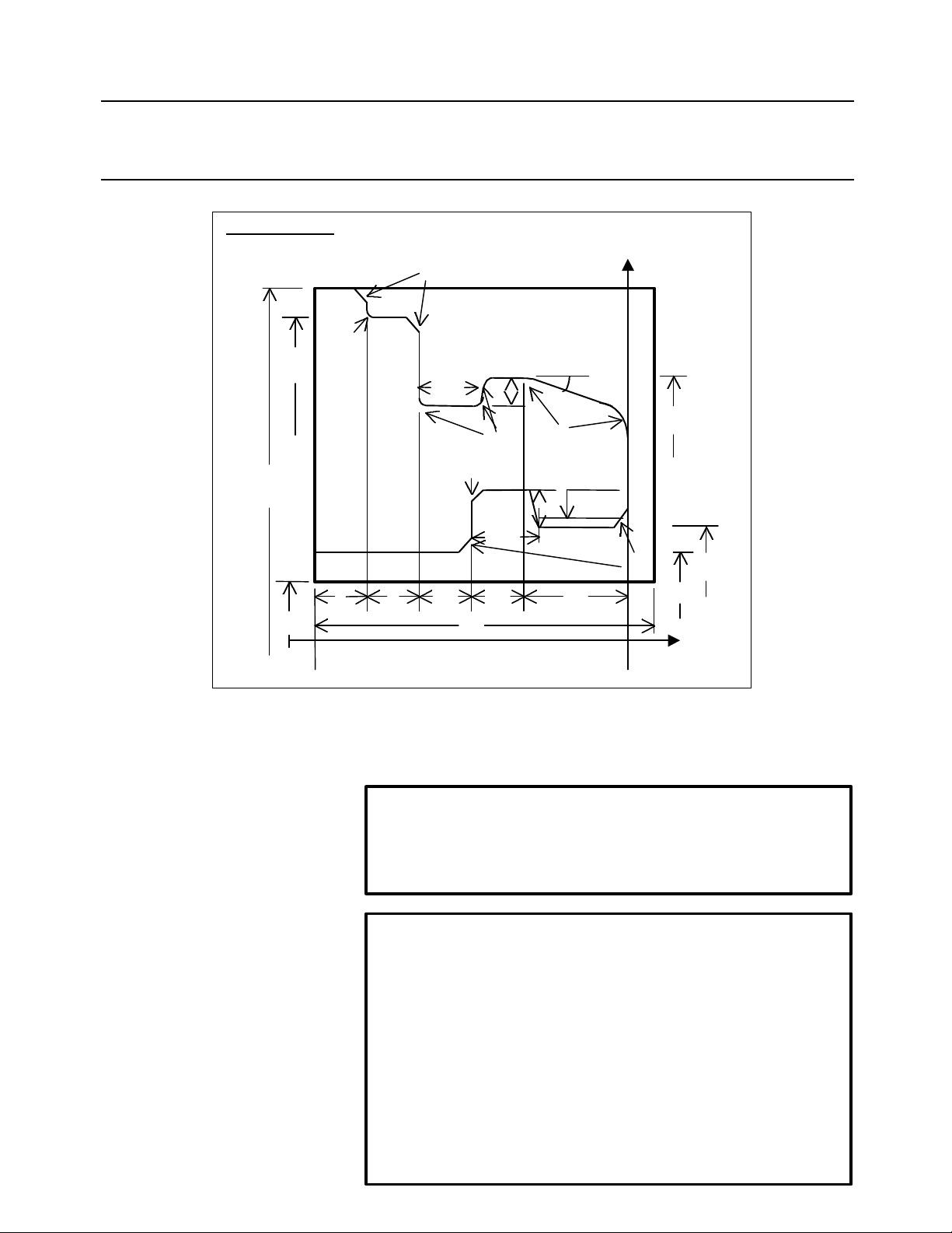
B-62824EN/02 3. PROGRAMMING EXAMPLE
-43-
3.1.3 Example of operation
Material : A L ∇∇
ø120
ø110
ø20
10
R1
C2
13
X
5
15°
ø90
R1
C1
15
10 201010
65
R5
M40×2
5
C2
ø37.402
ø30
Z
This section presents an example of the machining performed according to the
above drawing. This example does not use fully automatic process determination,
but assumes that the machining conditions need not be modified.
NOTE
This example assumes that the values of the cutting condition data,
tool/tooling data, NC machine setting, standard value setting, and
operation setting items are the initial values immediately after setup.
WARNING
Before starting machining based on NC data prepared according to
this example, thoroughly check the contents of the NC data to ensure
that the tool path and machining processes are set correctly, and that
the tool will not collide with the workpiece or machine (including the
chuck and tailstock). Before starting a production run, perform a dry
run to ensure that the tool will not collide with the workpiece or
machine (including the chuck and tailstock). For example, start the
NC data without mounting a workpiece on the machine. Any
collision can cause damage to the tool, machine, and/or workpiece,
or injury to the user.
Page 64

3. PROGRAMMING EXAMPLE B-62824EN/02
-44-
(1) Blank figure creation
Click the Blank Figure Creation button, then enter data for each item
as follows:
Material A L
Blank figure Tube
Blank size Diameter : 120.0
Inner dia. : 20.0
Length : 65.0
Base point : 5.0
Standard SR : SR-Mark 2
(2) Part figure creation
Click the Part Figure Creation button to display the symbolic input
window. Then, enter part figure data by using the symbolic figure
input buttons, as follows:
Start point Start DX : 30.0
Start Z : 60.0
Straight line End Z: 30.0
Surface: SR-Mark 2
Chamfer Chamfer: 2.0
Surface: SR-Mark 2
Straight line End DX: 37.402
Surface: SR-Mark 2
Grooving Type: Trapezoid
Surface: SR-Mark 2
Last or Next: On Next element
Direction:Up
Width: 15.0
Depth: 5.0
Bottom1: Angle
Angle: (Input not required)
Bottom2: Angle
Angle: 60.0
1st corner: None
2nd corner: Chamfer
2nd value: 1.0
3rd corner: None
4th corner: None
Straight line End Z: 0.0
Surface: SR-Mark 2
Page 65
B-62824EN/02 3. PROGRAMMING EXAMPLE
-45-
Threading Type: General thread
Last or Next: On Last
Length: 18.0
Internal
Lead: 2.0
Thread N: 1
Depth: 1.299
Angle: 60.0
Chamfer Chamfer: 2.0
Surface: SR-Mark 2
Straight line End DX: (Input not required)
Surface: SR-Mark 2
Corner R Corner R: 5.0
Surface: SR-Mark 2
Straight line End DX: 90.0
End Z: 20.0
Angle A: 15.0
Surface: SR-Mark 2
Corner R Corner R: 5.0
Surface: SR-Mark 2
Straight line End Z: 40.0
Surface: SR-Mark 2
Grooving Type: Normal
Surface: SR-Mark 2
Last or Next: On Last element
Direction:Down
Width: 13.0
Depth: 5.0
1st corner: Corner R
1st value: 1.0
2nd corner: Corner R
2nd value: 1.0
3rd corner: Corner R
3rd value: 1.0
4th corner: None
Straight line End DX: 110.0
Surface: SR-Mark 2
Chamfer Chamfer: 2.0
Surface: SR-Mark 2
Page 66

3. PROGRAMMING EXAMPLE B-62824EN/02
-46-
Straight line End Z: 50.0
Surface: SR-Mark 2
Corner R Corner R: 1.0
Surface: SR-Mark 2
Straight line End DX: 120.0
Surface: SR-Mark 2
Chamfer Chamfer: 2.0
Surface: SR-Mark 2
Straight line End Z: 55.0
Surface: SR-Mark 2
(3) Pre-machining settings
Click the Pre-machining Setting button to display the Setting of Premachining input window. Then, select the tooling and NC machine,
and specify a home position and index position as follows:
Select Tooling: Tooling 1
Select NC machine: FS16T/18T (Geometry)
Home position: DXH = 200.0, ZH = 200.0
Index position: DXI = 150.0, ZI = 150.0
(4) Machining definition
Click the Machining Definition button to display the Machining
Definition window. Then, select a machining type by clicking the
Machining Type button in the Addition group.
Page 67

B-62824EN/02 3. PROGRAMMING EXAMPLE
-47-
• Hole machining
=> Hole => Drilling
When a machining type is selected, the machining conditions and cutting
area are determined automatically. To modify the machining conditions,
click the Machining Condition button to display the Machining
Condition window. To modify the cutting area, first modify the value of
Depth, then click the Auto button.
To change the cutting area, first change the [Bottom Pos.], then click the
[Auto] button.
• Outer surface rough machining (rough end facing)
=> Rough => Outer
When a machining type is selected, the machining conditions and cutting
area are determined automatically. To modify the machining conditions,
click the Machining Condition button to display the Machining
Condition window. To modify the cutting area, select the first and second
division points, move the division points with the cursor keys, then specify
directions with the numeric keypad.
Page 68

3. PROGRAMMING EXAMPLE B-62824EN/02
-48-
• Outer surface rough machining
In the above state, click the separate area specification button . Then,
the machining conditions and cutting area are determined automatically. To
modify the machining conditions, click the Machining Condition button
to display the Machining Condition window. To modify the cutting
area, select the first and second division points, move the division points
with the cursor keys, then specify directions with the numeric keypad.
Page 69

B-62824EN/02 3. PROGRAMMING EXAMPLE
-49-
• Inner surface rough machining
⇒ Rough ⇒ Inner
When a machining type is selected, the machining conditions and cutting
area are determined automatically. To modify the machining conditions,
click the Machining Condition button to display the Machining
Condition window. To modify the cutting area, select the first and second
division points, move the with points the cursor keys, then specify directions
with the numeric keypad.
• Outer surface finish machining
⇒ Finish ⇒ Outer
The machining conditions and cutting area are determined automatically. To
modify the machining conditions, click the Machining Condition button
to display the Machining Condition window. To modify the cutting
area, select the first and second division points, move the division points
with the cursor keys, then specify directions with the numeric keypad.
Page 70

3. PROGRAMMING EXAMPLE B-62824EN/02
-50-
• Inner surface finish machining
⇒ Finish => Inner
The machining conditions and cutting area are determined automatically. To
modify the machining conditions, click the Machining Condition button
to display the Machining Condition window. To modify the cutting
area, select the first and second division points, move the division points
with the cursor keys, then specify directions with the numeric keypad.
Page 71

B-62824EN/02 3. PROGRAMMING EXAMPLE
-51-
• Outer grooving
⇒ Rough Finish Groove => Outer
The machining conditions and cutting area are determined automatically. To
modify the machining conditions, click the Machining Condition button
to display the Machining Condition window.
• Inner grooving
⇒ Rough Finish Groove => Inner
The machining conditions and cutting area are determined automatically. To
modify the machining conditions, click the Machining Condition button
to display the Machining Condition window.
Page 72

3. PROGRAMMING EXAMPLE B-62824EN/02
-52-
• Inner threading
⇒ Thread => Inner
The machining conditions and cutting area are determined automatically. To
modify the machining conditions, click the Machining Condition button
to display the Machining Condition window.
Page 73

B-62824EN/02 3. PROGRAMMING EXAMPLE
-53-
(5) NC data preparation
Click the NC Data Preparation button to display the NC Data Preparation
window. Next, click the start button . Then, the NC data is created.
After the NC data has been created, click the execution list display button
to display the NC data.
Page 74
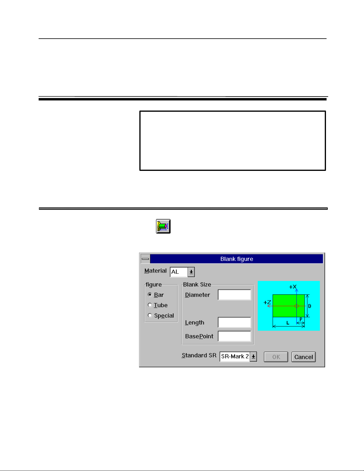
4. BLANK FIGURE CREATION B-62824EN/02
-54-
4 BLANK FIGURE CREATION
WARNING
Enter correct blank figure data. Failure to enter correct data may
result in the tool colliding with the workpiece and/or machine,
possibly causing damage to the machine, workpiece, and/or tool
itself, or injury to the user when machining is performed based on the
NC data.
4.1 Blank Figure Creation
Click on the side menu to display the following conversational
window:
Material
Select a material name from the displayed list. The material names
registered in the machining condition data are displayed.
Blank figure (Bar, Tube, Special figure)
Select a type of blank figure.
Page 75

B-62824EN/02 4. BLANK FIGURE CREATION
-55-
Standard SR
The value specified here serves as the initial surface roughness for a turning
figure.
Blank size (when Bar or Tube is selected)
Specify the diameter, inner diameter (when Tube is selected), length, and
base point of the blank.
As the base point, specify the distance from the face to the origin of the
program coordinate system.
Page 76

4. BLANK FIGURE CREATION B-62824EN/02
-56-
4.2 Special Figure
When Special figure is selected, the following conversational window
appears:
Click OK. Then, the special figure creation window appears.
A special figure can be created by means of the symbolic input method. For
details of the symbolic input method, see Chapter 5.
Page 77
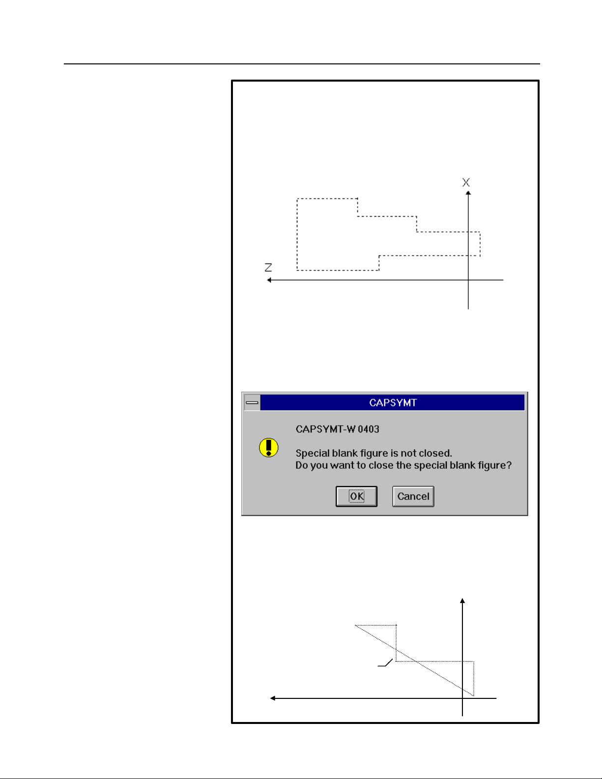
B-62824EN/02 4. BLANK FIGURE CREATION
-57-
NOTES
• When Special figure is selected, a threading figure, grooving figure,
nor necking figure cannot be specified.
• In special figure creation, use the positive area (including 0) along
the X-axis. If a negative X coordinate is specified, machining
definition and animated simulation may not be performed normally.
• For special figure creation, the start point must be the same as the
end point. Otherwise, the warning message shown below is output
when the End button is clicked. If OK is clicked in response to this
message, a connection is automatically established between the start
and end points.
• Create a special figure with a single stroke. Crossing points, like
those shown below, are not allowed.
X
Cross point
Z
Page 78
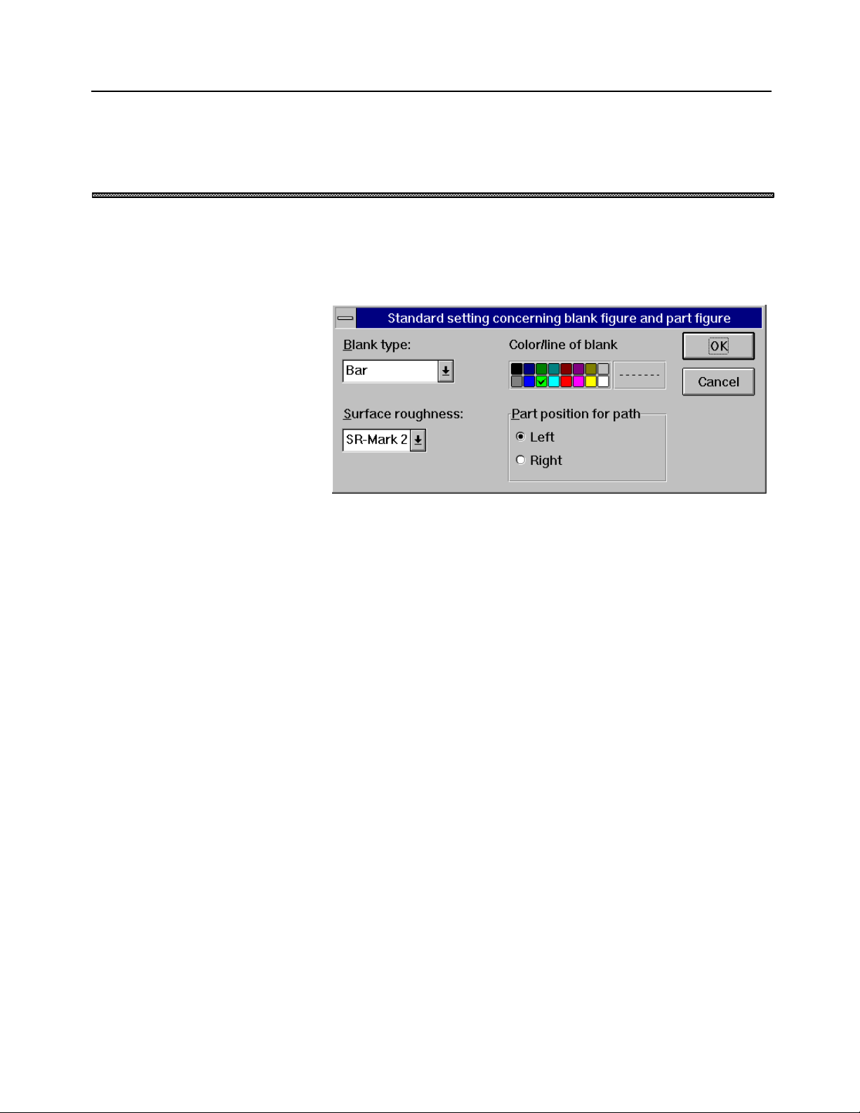
4. BLANK FIGURE CREATION B-62824EN/02
-58-
4.3 Blank Figure Color/Line Type Modification
When “Setting => Standard Setting => Blank Figure, Parts Figure” is
selected from the menu bar, the following conversational window appears to
enable blank figure color/line type modification:
The results of a modification made using this conversational window are
reflected when a blank figure is next modified, or a new blank figure is
created. A light green, thin dotted line is initially set.
Page 79
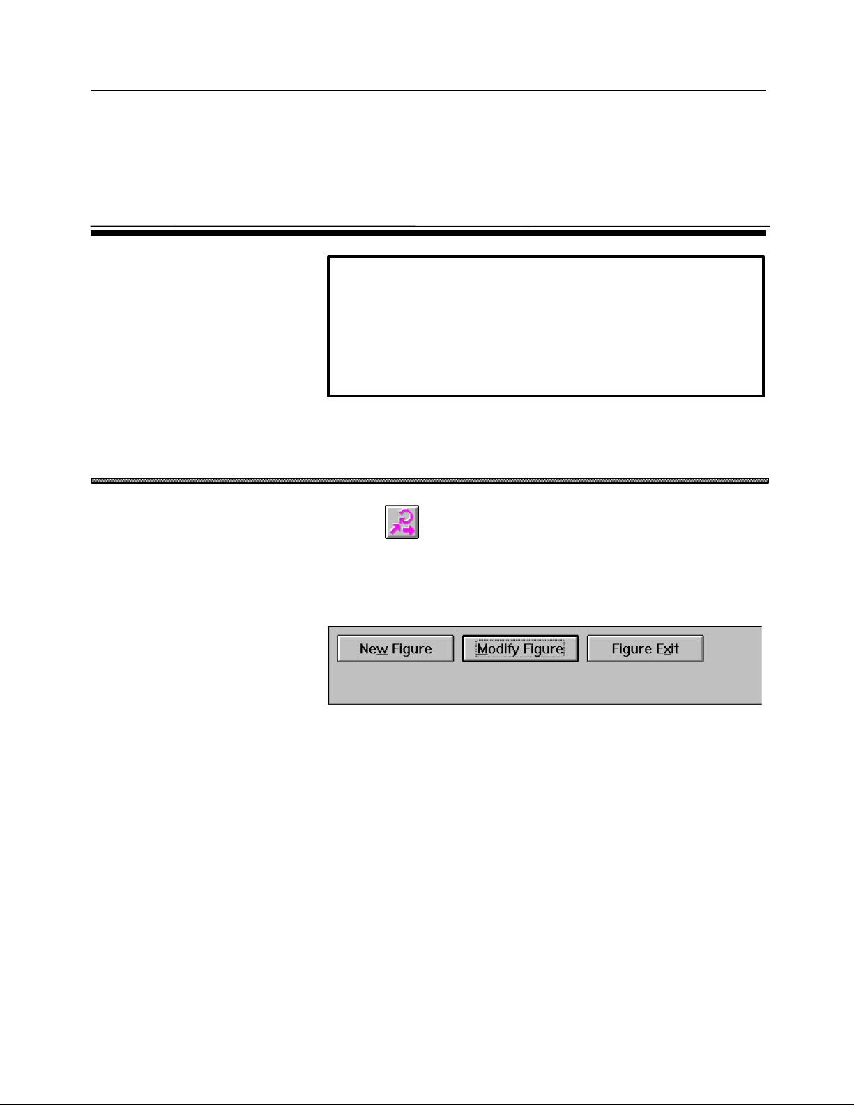
B-62824EN/02 5. PARTS FIGURE CREATION
-59-
5 PARTS FIGURE CREATION
WARNING
Enter correct parts figure data. Failure to enter correct data may
result in the tool colliding with the workpiece and/or machine,
possibly causing damage to the machine, workpiece, and/or tool
itself, or injury to the user when machining is performed based on the
NC data.
5.1 Turning Figure Creation
Click the button on the side menu to display the first symbolic input
window. Note, however, that when a new figure is to be created, the first
symbolic input window is skipped, the second symbolic input window being
displayed immediately.
[First Symbolic Input Window]
New Figure button
This button is used to delete a previously created figure, and create a new
figure.
Modify Figure button
This button is used to edit a part of an existing figure.
Figure Exit button
This button is used to terminate figure creation using the symbolic input
method.
Clicking the New Figure button or Modify Figure button causes the second
symbolic input window to be displayed. On this window, a figure can be
created using the arrow keys.
Page 80

5. PARTS FIGURE CREATION B-62824EN/02
-60-
Figure Scroll Bar Symbolic List Symbolic buttons
Reference
button
[Second Symbolic Input Window]
Symbolic buttons
The symbolic buttons are used to select the element used to constitute a
figure.
The user can select Straight line, Arc, Round, Chamfer, Grooving,
Threading, and Necking entities. Clicking a symbolic button causes a
conversational window to be displayed, thus enabling the user to enter an
end point and so forth.
Symbolic list
The buttons corresponding to the entities are displayed as a row, called the
symbolic list. Up to 10 buttons can be displayed at any one time. The
hidden buttons can be displayed by using the scroll bar.
Scroll bar
The scroll bar is used to scroll the symbolic list. The symbolic list can be
scrolled by clicking the left-hand or right-hand arrow button. A desired
figure entity on the symbolic list can be displayed by clicking and dragging
the corresponding square button on the scroll bar.
The display of the symbolic list can also be scrolled by pressing the Tab key
to move the focus to the scroll bar and then pressing the “←” or “→” key.
Delete button
Clicking this button deletes selected entity from the symbolic list.
Alter button
Clicking this button displays a conversational window for entering data for
selected entities in the symbolic list.
Exit button
Clicking this button terminates figure creation. When the Exit button is
clicked, the end point of each figure entity is automatically calculated. If an
error is detected in the entered data during end point calculation, an error
message is displayed.
Figure Reference button
Clicking this button registers figures created using the figure creation function or
those entered using the CAD data input function, as entities for creating a figure.
Page 81

B-62824EN/02 5. PARTS FIGURE CREATION
-61-
5.2 Symbolic Input Method
5.2.1 Entity selection
Using the symbolic buttons shown below, select Straight line, Arc, Round,
Chamfer, Grooving, Threading, or Necking entities.
Entities can be selected in either of the following ways:
• Click the desired buttons on the conversational window.
• By using the keyboard, enter the number or alphabet that appears in
the lower-right corner of each desired button on the conversational
window.
For the figure shown above, click the following symbolic buttons in the
order shown around the outline of the figure.
Page 82

5. PARTS FIGURE CREATION B-62824EN/02
-62-
is represented the end of a figure, and cannot be deleted.
5.2.2 Symbolic figure data input
When a symbolic button is clicked, a conversational window appears to
enable the user to enter an end point and so forth. On this window, enter
only those items that appear on the drawing. Any items that do not appear
on the drawing need not be entered. Click OK or press the Enter key to
create the figure. A created figure is displayed in the symbolic list. The
selected entities can be invalidated by clicking the Cancel button or by
pressing the Esc key.
If sufficient data is not entered to create a figure, a warning message is
displayed.
To enter an increment, key in a value followed by the letter I in the edit box.
The direction of increment is indicated using the algebraic sign of the value
entered rather than an arrow. The value entered in the edit box is converted
to absolute coordinates instantly when the letter I is entered.
Example: 25I
A value corresponding to the current position plus 25 is displayed in the edit
box.
Page 83

B-62824EN/02 5. PARTS FIGURE CREATION
-63-
(1) Start point (Symbolic input)
When the first entity is selected, the following conversational window
appears to prompt the user to specify the start point of the figure:
Parts position for path
Specify the side where the figure to be entered is located, as viewed in
the direction of the arrow for the selected entity.
(2) Straight line (Symbolic input)
When any of symbolic buttons is
clicked, the following conversational window appears to enable straight
line entity input.
End DX
Enter the X coordinate of the end point of the straight line, using a
diameter value.
End Z
Enter the Z coordinate of the end point of the straight line.
Angle A
Enter the angle between the Z-axis and the straight line.
Page 84
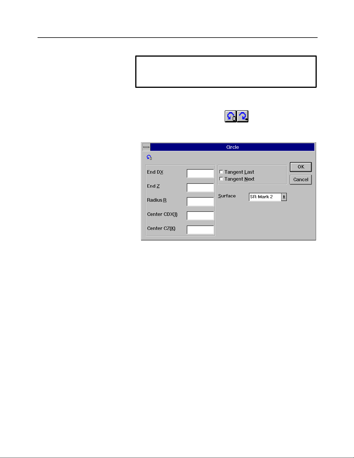
5. PARTS FIGURE CREATION B-62824EN/02
-64-
NOTE
Some items may not be displayed, depending on the type of straight
line and the figure data for the previous entity.
(3) Arc (Symbolic input)
When any of symbolic buttons is clicked, the following
conversational window appears to enable arc entity input
End DX
Enter the X coordinate of the end point of the arc, using a diameter
value.
End Z
Enter the Z coordinate of the end point of the arc.
Radius R
Enter the radius of the arc.
Center CDX
Enter the X coordinate of the arc center, using a diameter value.
Center CZ
Enter the Z coordinate of the arc center.
Tangent Last
Specify whether the arc is tangent to the previous entity.
Tangent Next
Specify whether the arc is tangent to the next entity.
Page 85

B-62824EN/02 5. PARTS FIGURE CREATION
-65-
When multiple intersections occur
The following conversational window is displayed if multiple
intersections (contact points) occur when a straight line intersects (or
touches) an arc, or if an arc intersects (or touches) another arc:
Select the position of an intersection, as viewed from the arc center,
with the following buttons:
: Up (also selectable with the 8 key)
: Down (also selectable with the 2 key)
: Left (also selectable with the 4 key)
: Right (also selectable with the 6 key)
(4) Chamfer (Symbolic input)
When symbolic button is clicked, the following conversational
window appears to enable chamfer entity input.
Page 86

5. PARTS FIGURE CREATION B-62824EN/02
-66-
Chamfer
Enter a chamfer value.
Surface
The standard SR value, set on the conversational window for blank
figure creation, is displayed as the initial value. Change the value
according to the drawing. The feedrate for finish machining is
automatically determined according to the surface roughness set here.
(5) Round (Symbolic input)
When symbolic button is clicked, the following conversational
window appears to enable round (corner R) entity input.
Page 87

B-62824EN/02 5. PARTS FIGURE CREATION
-67-
Corner R
Enter a radius for corner R.
Surface
The standard SR value, set using the conversational window for blank
figure creation, is displayed as the initial value. Change the value
according to the drawing. The feedrate for finish machining is
automatically determined according to the surface roughness set here.
(6) Threading (Symbolic input)
When symbolic button is clicked, the following conversational
window appears to enable threading entity input.
Page 88

5. PARTS FIGURE CREATION B-62824EN/02
-68-
Type
As the type, select General thread, Metric thread, Unified screw, PT/PF
thread, or Trapezoidal screw. Once a type has been selected, the fields
for setting data for that type appear. If PT/PF screw is selected, the taper
angle for threading is not determined. Instead, the angle of the
immediately preceding or following straight line entity is adopted as the
taper angle for threading.
Last or Next
Specify whether to create a threading entity on the next entity or on the
previous entity. Note that this specification determines the direction of
threading.
When are clicked in the order shown, and the On Next
entity is selected
When are clicked in the order shown, and the On Last
entity is selected
Page 89

B-62824EN/02 5. PARTS FIGURE CREATION
-69-
Length
Specify the length of the threading. When chamfering is used, the
length of the threading must be calculated starting at the intersection of
the straight line entities before chamfering.
External/Internal/Face
Select a threading type. The constant applied to automatic thread depth
calculation varies with the type of the threading. This item is valid only
when automatic thread depth calculation is specified. For some types of
threading, this item need not be selected. The initial values for the
constants are as follows:
External/Face: 0.7578
Internal: 0.6495
When Setting => Parameter Setting => Blank figure, Parts figure is
selected from the menu bar, the conversational window for constant
modification appears.
Lead and Thread N
The lead value is the distance traveled along the Z-axis for each rotation
of the thread. For a single thread, the lead is equal to the pitch. For an
n-start thread, the lead multiplied by 1/n equals the pitch. For a taper
thread, the lead calculation is made along the Z-axis.
Depth
For a general thread, the thread depth is calculated using the following
formula:
(Thread depth) = ((lead)/(number of starts)) × (thread constant)
When a lead value and a number of starts (Thread N) are set, the thread
depth is calculated automatically. If an automatically calculated thread
depth is modified, however, thread depth calculation is not repeated if
the lead and the number of starts (Thread N) are changed again.
Page 90
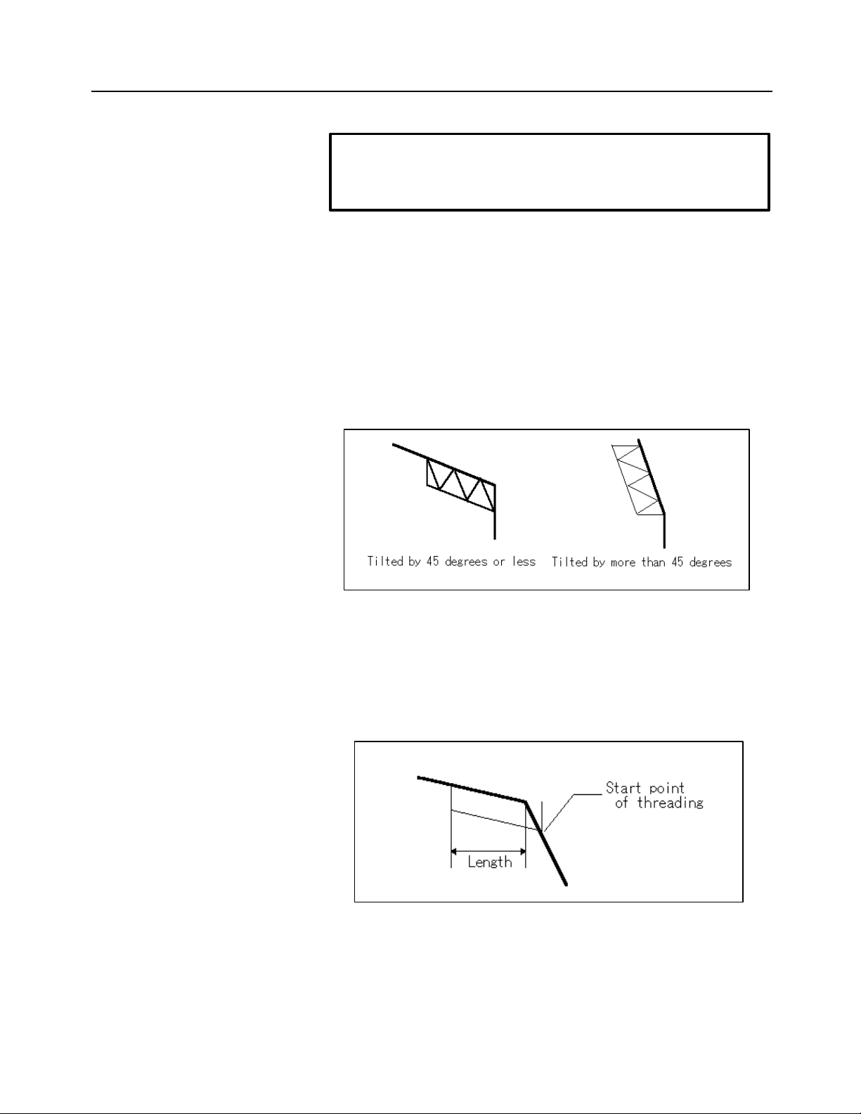
5. PARTS FIGURE CREATION B-62824EN/02
-70-
NOTE
For a unified screw or PT/PF screw, an automatic thread depth
calculation is performed if the number of crests per inch is specified.
Angle
Specify a thread angle between 0 and 90 .
When the straight line entity on which a threading entity is placed is
tapered
When the straight line entity is tilted by up to 45 degrees relative to the
Z-axis, the thread is an external thread or internal thread. When the
straight line entity is tilted by more than 45 degrees relative to the Zaxis, the thread is a face thread.
When the straight line entity immediately following a threading entity
is tapered
Threading starts at the intersection of the straight line connecting the
thread roots and the subsequent straight line entity.
In this case, note that the length of the thread actually produced will
differ from the specified length.
Page 91

B-62824EN/02 5. PARTS FIGURE CREATION
-71-
(7) Grooving (Symbolic input)
When symbolic button is clicked, the following conversational
window appears to enable grooving entity input:
Type
Select Normal, Slant, or Trapezoid as the type of groove.
a. Normal grooving (Symbolic input)
Surface
The standard SR value, set using the conversational window for blank
figure creation, is displayed as the initial value. Change the value
according to the drawing. The feedrate for finish machining is
automatically determined according to the surface roughness set here.
Last or Next
Specify whether to create a groove on the next entity or on the previous
entity.
Page 92

5. PARTS FIGURE CREATION B-62824EN/02
-72-
When are clicked in the order shown
Width
Specify the width of a groove. When a trapezoidal groove is to be
created, specify the width of the opening. Note that if the groove width
extends over two or more entities, a groove figure cannot be created.
Depth
Specify a groove depth.
Direction
Specify the direction of the groove to be created, by selecting one of the
arrows, as shown below.
1st corner/2nd corner/3rd corner/4th corner
For the corners of a groove, chamfer or corner R can be specified. When
chamfer or corner R is selected, specify a chamfer value or a radius for
corner R in response to the corner value input prompt.
Corner numbers are assigned in the order of the figure advance direction.
When are clicked
Page 93
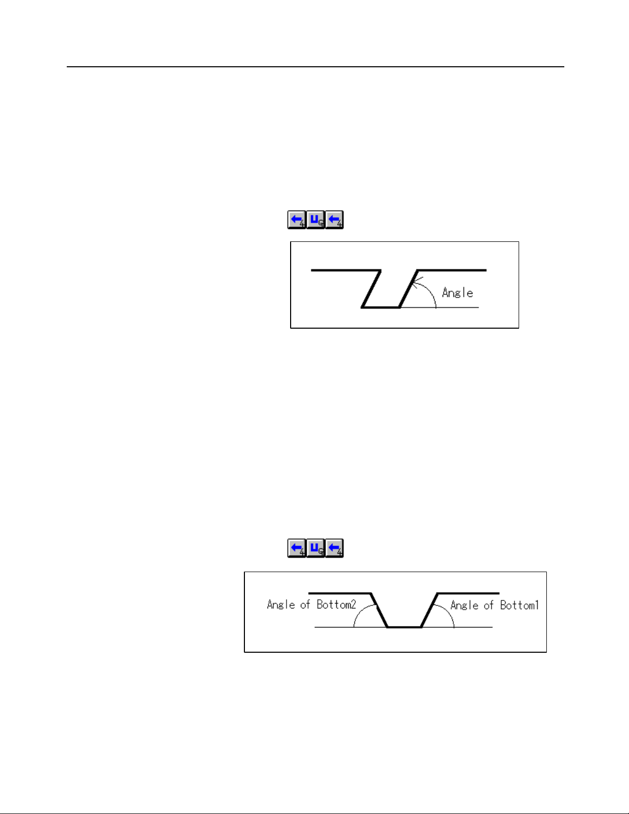
B-62824EN/02 5. PARTS FIGURE CREATION
-73-
b. Slanted grooving (Symbolic input)
In addition to the data entry fields for Normal, a field for specifying the
angle is also displayed.
Angle
Specify the angle of the wall of the groove to be created.
When are clicked in the order shown
c. Trapezoid grooving (Symbolic input)
In addition to the data entry fields for Normal, a field for bottom
specification and another for width specification are displayed.
Bottom1, Bottom2
Select Angle or Width.
Angle
When Angle is selected in bottom specification, specify the angles
shown below. The order in which these angles are specified depends on
the advance direction of the figure.
When are clicked in the order shown
Width
When Width is selected in bottom specification, set the widths shown
below. The order in which these widths are specified depends on the
advance direction of the figure.
Page 94

5. PARTS FIGURE CREATION B-62824EN/02
-74-
When are clicked in the order shown
NOTE
No grooving entity is drawn until the next entity has been determined.
(8) Necking (Symbolic input)
When symbolic button is clicked, the following conversational
window appears to enable necking entity input.
Type
Select General, Grinding1, Grinding2, or Threading necking as the
necking type.
When Grinding1 or Grinding2 is selected, a necking width, necking
depth, and corner value are determined automatically (according to the
DIN standard), provided the previous figure has already been defined.
When Threading necking is selected, a necking width, necking depth,
and corner value are determined provided the previous figure has
Page 95
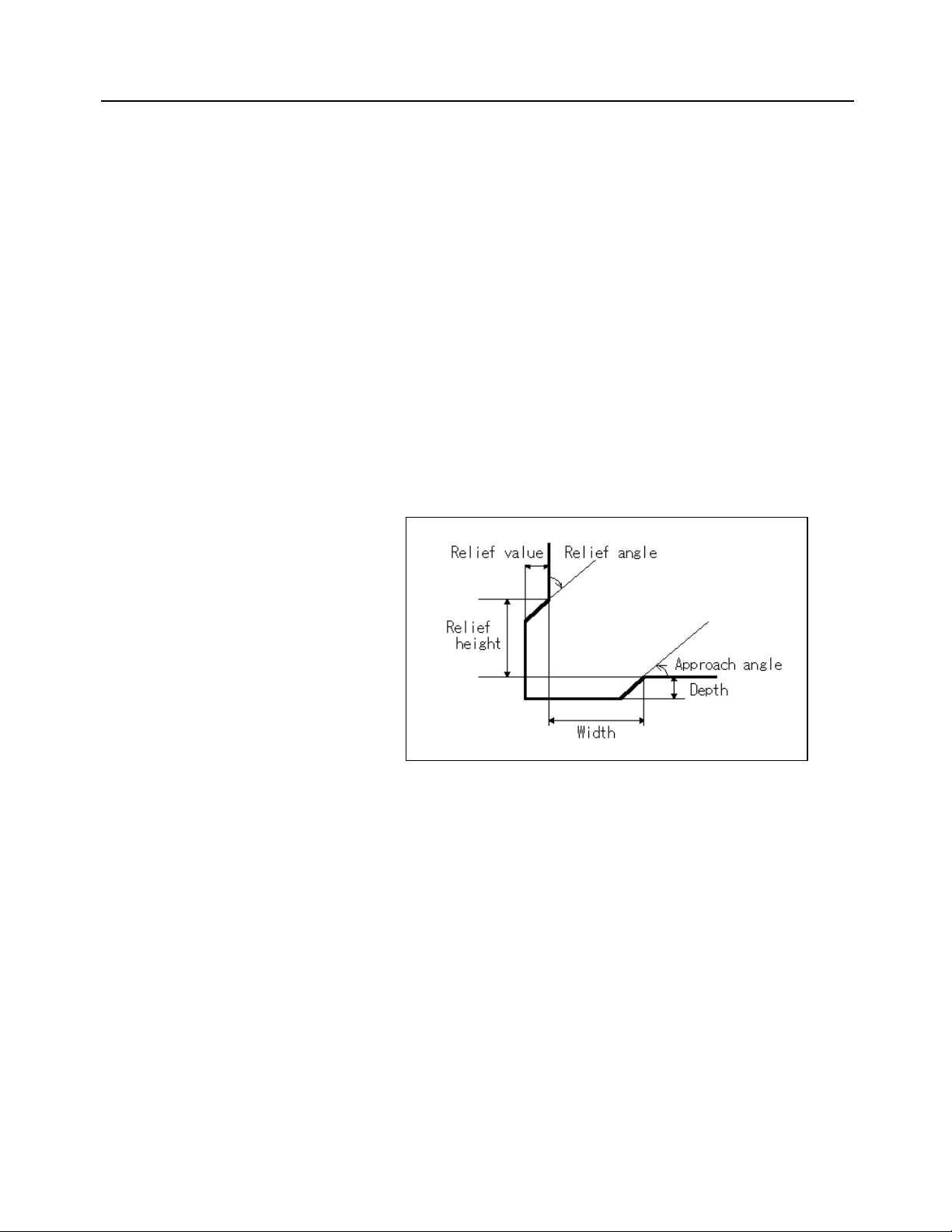
B-62824EN/02 5. PARTS FIGURE CREATION
-75-
already been defined, and that that figure is subsequent to a threading
figure.
Surface
The standard SR value, set using the conversational window for blank
figure creation, is displayed as the initial value. Change the value
according to the drawing. The feedrate for finish machining is
automatically determined according to the surface roughness set here.
a. General necking (Symbolic input)
When General is selected as the type of necking, the data entry fields
shown below appear.
Width/Depth/Approach angle/Relief value/Relief height/
Relief angle
1st corner/2nd corner/3rd corner/4th corner/5th corner
For necking angle setting, chamfer or corner R can be specified. When
chamfer or corner R is selected, specify a chamfer value or a radius for
corner R in response to the prompt for corner value input.
Page 96

5. PARTS FIGURE CREATION B-62824EN/02
-76-
Numbers are assigned to the corners of a necking figure as shown
below.
b. Grinding necking 1 (Symbolic input)
When Grinding1 is selected as the type of necking, the data entry fields
shown below appear.
Width/Depth/Approach angle/1st corner/2nd corner
The initial width, depth, and corner value indicated in the table shown
below are set. An approach angle of 15 degrees is initially set.
c. Grinding necking 2 (Symbolic input)
When Grinding2 is selected as the type of necking, the data entry fields
shown below appear.
Width/Depth/Approach angle/Relief angle/Relief value/1st corner/2nd
corner
The initial width, depth, relief value, and corner value indicated in the
table shown below are set. An approach angle of 15 degrees, and a
relief angle of 8 degrees are initially set.
Page 97

B-62824EN/02 5. PARTS FIGURE CREATION
-77-
The initial values indicated in the table shown below are set in the fields
for Grinding1 and Grinding2, according to the X coordinate of the
previous straight line entity:
Diameter
(X coordinate)
Less than 18 mm
Less than 0.7087 inch
18 mm to 80 mm
0.7087 to 3.15 inch
80 mm or more
3.15 inch or more
Width Depth Corner
2.0 mm
0.0787 inch
2.5 mm
0.0984 inch
4.0 mm
0.1575 inch
0.25 mm
0.0098 inch
0.35 mm
0.0138 inch
0.45 mm
0.0177 inch
value
0.6 mm
0.0236 inch
0.6 mm
0.0236 inch
1.0 mm
0.0394 inch
0.1 mm
0.0039 inch
0.2 mm
0.0079 inch
0.3 mm
0.0118 inch
d. Threading necking (Symbolic input)
When Threading necking is selected as the type of necking, the prompts
shown below appear.
Width/Depth/Approach angle/1st corner/2nd corner
The width, depth, and corner value calculated using the formulas given
below are initially set. The pitch and thread depth values entered for the
subsequent threading entity are used. If the subsequent entity is other
than a threading entity, no initial value calculation is performed.
Relief
value
Width = 3.5 × pitch
Depth = 1.2 × thread depth
Corner value = 0.5 × pitch
Page 98

5. PARTS FIGURE CREATION B-62824EN/02
-78-
An approach angle of 30 degrees is initially set.
NOTE
• A necking entity is not drawn until the next entity has been
determined.
• Necking cannot extend over three or more successive entities.
• A necking entity must be created between a horizontal straight line
and a vertical straight line.
5.2.3 Symbolic Figure data editing
(1) Selecting entities (Symbolic Figure data editing)
The symbolic list button for the currently selected entity is displayed as
though it has been physically pressed. To select another entity, click the
corresponding button in the symbolic list.
The currently selected entity can be shifted one entity to right by pressing
the + key on the keyboard. Similarly, the currently selected entity can be
shifted one entity to left by pressing the – key.
(2) Deleting entities (Symbolic Figure data editing)
To delete an entity, select the entity from the symbolic list, then click the
Delete button. When an attempt is made to delete the first entity, the
conversational window for setting a start point is displayed. Specify an
appropriate start point.
(3) Inserting entities (Symbolic Figure data editing)
To insert an entity between another two entities, select the latter of the two
entities in the symbolic list. Then, from the symbolic buttons, select the
entity to be inserted. The conversational window for the selected entity is
displayed. Then, enter the required data.
Page 99

B-62824EN/02 5. PARTS FIGURE CREATION
-79-
(4) Modifying figure data (Symbolic Figure data editing)
To modify figure data select, from the symbolic list, the entity to be
modified, then click the Alter button. The conversational window for the
selected entity appears. Then, modify the data as required. When an
attempt is made to modify the first entity, the conversational window for
setting a start point is displayed. Specify an appropriate start point.
NOTE
If the figure data is edited, the drawing may not be updated
immediately. This is because intersection calculations will not yet
have been made for the entities subsequent to that currently selected
in the symbolic list. By advancing from the currently selected entity
to the next, the intersection calculation required to update the
drawing can be instigated. Note that the drawing of an entity such as
a chamfer entity, round entity, threading entity, grooving entity, and
necking entity is not updated until the next entity is selected.
(5) Redo and undo (Symbolic figure input)
During symbolic input, the redo and undo operations are disabled. If a
redo operation is performed after the completion of symbolic input, the
state existing before the start of symbolic input is restored. Subsequently
performing an undo operation would restore the state existing at the
termination of symbolic input. So, to abandon the editing of a figure for
whatever reason, terminate symbolic input, then execute the undo
operation.
(6) Color/line of parts figure
When Setting => Parameter Setting => Blank Figure, Parts Figure is
Changeselected from the menu bar, the conversational window enabling
part figure color/line modification appears.
Page 100

5. PARTS FIGURE CREATION B-62824EN/02
-80-
Select the item to be modified, then modify its color and line width.
Multiple figure types can be selected together for color and line
modification. If modification is performed during symbolic input, the
modification is not immediately reflected in the drawing; the modification
is not reflected in the drawing until after symbolic input has terminated,
and the next symbolic input operation is started.
The initial settings are as follows:
Parts figure : Light red
Undefined : Pale yellow
Threading/grooving/necking : Light blue
Selected figure : Pale yellow
Selected point : Light blue
5.2.4 Symbolic figure creation by figure reference
(1) Overview (Symbolic figure creation by figure reference)
By means of the symbolic input function, the user can create a symbolic
figure by entering figure-related data on the input window from the
keyboard. With the symbolic figure creation function based on figure
reference, however, the user creates a symbolic figure by selecting a figure
that was previously created by using the drawing function, rather than by
entering figure data from the keyboard.
Thus, the user can create a symbolic figure as if the selected figure data
had been automatically entered with the data input window.
The symbolic figure creation function based on figure reference can be
used to create parts figures and special figures.
Figures that can be referenced
(a) Figures created with the figure creation function
(b) Figures entered with the CAD data input function
(c) Figures created with the figure creation function of the FANUC
PC FAPT series
Types of figures that can be referenced
(a) Straight lines parallel to the machining plane
(b) Circles parallel to the machining plane
(c) Arcs parallel to the machining plane
(d) Polylines/polygons parallel to the machining plane
(e) Fitting curves parallel to the machining plane
 Loading...