

Fanuc AC SERVO Motor αis, AC SERVO Motor αi, SERVO AMPLIFIER αi, AC Spindle Motor αi Maintenance Manual
Page 1

FANUC AC SERVO MOTOR @*s series
@
FANUC AC SERVO MOTOR @* series
FANUC AC SPINDLE MOTOR
FANUC SERVO AMPLIF
IER @* series
MAINTENANCE MANUAL
* series
B-65285EN/03
Page 2

Ȧ No part of this manual may be reproduced in any form.
Ȧ All specifications and designs are subject to change without notice.
In this manual we have tried as much as possible to describe all the
various matters.
However , we cannot describe all the matters which must not be done,
or which cannot be done, because there are so many possibilities.
Therefore, matters which are not especially described as possible in
this manual should be regarded as ”impossible”.
Page 3

B-65285EN/03 SAFETY PRECAUTIONS
SAFETY PRECAUTIONS
The "Safety Precautions" section describes the safety precautions
relating to the use of FANUC servo motors, spindle motors, and servo
amplifiers (power supply modules, servo amplifier modules, and
spindle amplifier modules). Users of any servo motor or amplifier
model are requested to read the "Safety Precautions" carefully before
using the servo motor or amplifier.
The users are also requested to read an applicable specification manual
carefully and understand each function of the motor or amplifier for
correct use.
The users are basically forbidden to do any behavior or action not
mentioned in the "Safety Precautions." They are invited to ask FANUC
previously about what behavior or action is prohibited.
Contents
1.1 DEFINITION OF WARNING, CAUTION, AND NOTE.........s-2
1.2 FANUC AC SERVO MOTOR αis/αi series
FANUC AC SPINDLE MOTOR αi series................................s-3
1.2.1Warning ...........................................................................s-3
1.2.2Caution ...........................................................................s-6
1.2.3Note ...........................................................................s-7
1.3 FANUC SERVO AMPLIFIER αi series ...................................s-9
1.3.1Warnings and Cautions Relating to Mounting ..................s-9
1.3.1.1 Warning.............................................................s-9
1.3.1.2 Caution ............................................................s-11
1.3.1.3 Note .................................................................s-13
1.3.2Warnings and Cautions Relating to a Pilot Run ..............s-14
1.3.2.1 Warning...........................................................s-14
1.3.2.2 Caution ............................................................s-15
1.3.3Warnings and Cautions Relating to Maintenance ...........s-16
1.3.3.1 Warning...........................................................s-16
1.3.4.2 Caution ............................................................s-18
1.3.4.3 Note .................................................................s-19
s-1
Page 4
SAFETY PRECAUTIONS B-65285EN/03
1.1 DEFINITION OF WARNING, CAUTION, AND NOTE
This manual includes safety precautions for protecting the user and
preventing damage to the machine. Precautions are classified into
Warning and Caution according to their bearing on safety. Also,
supplementary information is described as a Note. Read the Warning,
Caution, and Note thoroughly before attempting to use the machine.
WARNING
Applied when there is a danger of the user being
injured or when there is a damage of both the user
being injured and the equipment being damaged if
the approved procedure is not observed.
CAUTION
Applied when there is a danger of the equipment
being damaged, if the approved procedure is not
observed.
NOTE
The Note is used to indicate supplementary
information other than Warning and Caution.
* Read this manual carefully, and store it in a safe place.
s-2
Page 5

B-65285EN/03 SAFETY PRECAUTIONS
1.2 FANUC AC SERVO MOTOR α
αis/ααααi series
αα
FANUC AC SPINDLE MOTOR ααααi series
1.2.1 Warning
WARNING
- Be safely dressed when handling a motor.
Wear safety shoes or gloves when handling a motor as you may
get hurt on any edge or protrusion on it or electric shocks.
- Use a crane or lift to move a motor from one place to another.
A motor is heavy. If you lift the motor by hand, you may get a
backache, or you may be seriously injured when you drop the
motor. A suitable crane or lift must be used to move the motor.
(For the weight of motors, refer to their respective specification
manuals.)
When moving a motor using a crane or lift, use a hanging bolt if
the motor has a corresponding tapped hole, or textile rope if it has
no tapped hole.
If a motor is attached with a machine or any other heavy stuff, do
not use a hanging bolt to move the motor as the hanging bolt
and/or motor may get broken.
- Before starting to connect a motor to electric wires, make
sure they are isolated from an electric power source.
A failure to observe this caution is vary dangerous because you
may get electric shocks.
- Be sure to secure power wires.
If operation is performed with a terminal loose, the terminal block
may become abnormally hot, possibly causing a fire. Also, the
terminal may become disconnected, causing a ground fault or
short-circuit, and possibly giving you electric shocks. See the
section in this manual that gives the tightening torque for
attaching power wires and short-bars to the terminal block.
- Be sure to ground a motor frame.
To avoid electric shocks, be sure to connect the grounding
terminal in the terminal box to the grounding terminal of the
machine.
- Do not ground a motor power wire terminal or short-circuit it
to another power wire terminal.
A failure to observe this caution may cause electric shocks or a
burned wiring.
(*) Some motors require a special connection such as a winding
changeover. Refer to their respective motor specification
manuals for details.
s-3
Page 6

SAFETY PRECAUTIONS B-65285EN/03
WARNING
- Do not supply the power to the motor while any terminal is
exposed.
A failure to observe this caution is very dangerous because you
may get electric shocks if your body or any conductive stuff
touches an exposed terminal.
- Do not bring any dangerous stuff near a motor.
Motors are connected to a power line, and may get hot. If a
flammable is placed near a motor, it may be ignited, catch fire, or
explode.
- Do not get close to a rotary section of a motor when it is
rotating.
You may get your clothes or fingers caught in a rotary section, and
may be injured. Before starting a motor, ensure that there is no
stuff that can fly away (such as a key) on the motor.
- Do not touch a motor with a wet hand.
A failure to observe this caution is vary dangerous because you
may get electric shocks.
- Before touching a motor, shut off the power to it.
Even if a motor is not rotating, there may be a voltage across the
terminals of the motor.
Especially before touching a power supply connection, take
sufficient precautions.
Otherwise you may get electric shocks.
- Do not touch any terminal of a motor for a while (at least 5
minutes) after the power to the motor is shut off.
High voltage remains across power line terminals of a motor for a
while after the power to the motor is shut off. So, do not touch any
terminal or connect it to any other equipment. Otherwise, you may
get electric shocks or the motor and/or equipment may get
damaged.
- To drive a motor, use a specified amplifier and parameters.
Driving a motor with other than the specified combinations of an
amplifier and parameters may cause the motor to perform an
unexpected operation; for example, the motor may get out of
control, or produce excessively high torque. This may result in the
motor or machine being damaged. Also, an object such as a
workpiece or tool may fly off due to excessive rotation, possibly
causing injury.
s-4
Page 7

B-65285EN/03 SAFETY PRECAUTIONS
- Do not touch a regenerative discharge unit for a while (at
least 30 minutes) after the power to the motor is shut off.
A regenerative discharge unit may get hot when the motor is
running.
Do not touch the regenerative discharge unit before it gets cool
enough. Otherwise, you may get burned.
- Do not touch a motor when it is running or immediately after
it stops.
A motor may get hot when it is running. Do not touch the motor
before it gets cool enough. Otherwise, you may get burned.
- Ensure that motors and related components are mounted
securely.
If a motor or its component slips out of place or comes off when
the motor is running, it is very dangerous.
- Be careful not get your hair or cloths caught in a fan.
Be careful especially for a fan used to generate an inward air flow.
Be careful also for a fan even when the motor is stopped, because
it continues to rotate while the amplifier is turned on.
- When designing and assembling a machine tool, make it
compliant with EN60204-1.
To ensure the safety of the machine tool and satisfy European
standards, when designing and assembling a machine tool, make it
compliant with EN60204-1. For details of the machine tool, refer
to its specification manual.
s-5
Page 8

SAFETY PRECAUTIONS B-65285EN/03
1.2.2 Caution
CAUTION
- FANUC motors are designed for use with machines. Do not
use them for any other purpose.
If a FANUC motor is used for an unintended purpose, it may
cause an unexpected symptom or trouble. If you want to use a
motor for an unintended purpose, previously consult with
FANUC.
- Ensure that a base or frame on which a motor is mounted is
strong enough.
Motors are heavy. If a base or frame on which a motor is mounted
is not strong enough, it is impossible to achieve the required
precision.
- Be sure to connect motor cables correctly.
An incorrect connection of a cable cause abnormal heat
generation, equipment malfunction, or failure. Always use a cable
with an appropriate current carrying capacity (or thickness). For
how to connect cables to motors, refer to their respective
specification manuals.
- Ensure that motors are cooled if they are those that require
forcible cooling.
If a motor that requires forcible cooling is not cooled normally, it
may cause a failure or trouble. For a fan-cooled motor, ensure that
it is not clogged or blocked with dust and dirt. For a liquid-cooled
motor, ensure that the amount of the liquid is appropriate and that
the liquid piping is not clogged.
For both types, perform regular cleaning and inspection.
- When attaching a component having inertia, such as a pulley,
to a motor, ensure that any imbalance between the motor and
component is minimized.
If there is a large imbalance, the motor may vibrates abnormally,
resulting in the motor being broken.
- Be sure to attach a key to a motor with a keyed shaft.
If a motor with a keyed shaft runs with no key attached, it may
impair torque transmission or cause imbalance, resulting in the
motor being broken.
s-6
Page 9

B-65285EN/03 SAFETY PRECAUTIONS
1.2.3 Note
NOTE
- Do not step or sit on a motor.
If you step or sit on a motor, it may get deformed or broken. Do
not put a motor on another unless they are in packages.
- When storing a motor, put it in a dry (non-condensing) place
at room temperature (0 to 40°°°°C).
If a motor is stored in a humid or hot place, its components may
get damaged or deteriorated. In addition, keep a motor in such a
position that its shaft is held horizontal and its terminal box is at
the top.
- Do not remove a nameplate from a motor.
If a nameplate comes off, be careful not to lose it. If the nameplate
is lost, the motor becomes unidentifiable, resulting in
maintenance becoming impossible.
For a nameplate for a built-in spindle motor, keep the nameplate
with the spindle.
- Do not apply shocks to a motor or cause scratches to it.
If a motor is subjected to shocks or is scratched, its components
may be adversely affected, resulting in normal operation being
impaired. Be very careful when handling plastic portions, sensors,
and windings, because they are very liable to break. Especially,
avoid lifting a motor by pulling its plastic portion, winding, or
power cable.
- Do not conduct dielectric strength or insulation test for a
sensor.
Such a test can damage elements in the sensor.
- When testing the winding or insulation resistance of a motor,
satisfy the conditions stipulated in IEC60034.
Testing a motor under a condition severer than those specified in
IEC34 may damage the motor.
- Do not disassemble a motor.
Disassembling a motor may cause a failure or trouble in it.
If disassembly is in need because of maintenance or repair, please
contact a service representative of FANUC.
- Do not modify a motor.
Do not modify a motor unless directed by FANUC. Modifying a
motor may cause a failure or trouble in it.
s-7
Page 10

SAFETY PRECAUTIONS B-65285EN/03
NOTE
- Use a motor under an appropriate environmental condition.
Using a motor in an adverse environment may cause a failure or
trouble in it.
Refer to their respective specification manuals for details of the
operating and environmental conditions for motors.
- Do not apply a commercial power source voltage directly to a
motor.
Applying a commercial power source voltage directly to a motor
may result in its windings being burned. Be sure to use a specified
amplifier for supplying voltage to the motor.
- For a motor with a terminal box, make a conduit hole for the
terminal box in a specified position.
When making a conduit hole, be careful not to break or damage
unspecified portions.
Refer to an applicable specification manual.
- Before using a motor, measure its winding and insulation
resistances, and make sure they are normal.
Especially for a motor that has been stored for a prolonged period
of time, conduct these checks. A motor may deteriorate depending
on the condition under which it is stored or the time during which
it is stored. For the winding resistances of motors, refer to their
respective specification manuals, or ask FANUC. For insulation
resistances, see the following table.
- To use a motor as long as possible, perform periodic
maintenance and inspection for it, and check its winding and
insulation resistances.
Note that extremely severe inspections (such as dielectric strength
tests) of a motor may damage its windings. For the winding
resistances of motors, refer to their respective specification
manuals, or ask FANUC. For insulation resistances, see the
following table.
MOTOR INSULATION RESISTANCE MEASUREMENT
Measure an insulation resistance between each winding and
motor frame using an insulation resistance meter (500 VDC).
Judge the measurements according to the following table.
Insulation resistance Judgment
100MΩ or higher Acceptable
10 to 100 MΩ The winding has begun deteriorating. There is no
problem with the performance at present. Be sure
to perform periodic inspection.
1 to 10 MΩ The winding has considerably deteriorated.
Special care is in need. Be sure to perform
periodic inspection.
Lower than 1 MΩ Unacceptable. Replace the motor.
s-8
Page 11

B-65285EN/03 SAFETY PRECAUTIONS
1.3 FANUC SERVO AMPLIFIER α
αi series
αα
1.3.1 Warnings and Cautions Relating to Mounting
1.3.1.1 Warning
WARNING
- Check the specification code of the amplifier.
Check that the delivered amplifier is as originally ordered.
- Mount a ground fault interrupter.
To guard against fire and electric shock, fit the factory power
supply or machine with a ground fault interrupter (designed for
use with an inverter).
- Securely ground the amplifier.
Securely connect the ground terminal and metal frame of the
amplifier and motor to a common ground plate of the power
magnetics cabinet.
- Be aware of the weight of the amplifier and other
components.
Control motor amplifiers and AC reactors are heavy. When
transporting them or mounting them in the cabinet, therefore, be
careful not to injured yourself or damage the equipment. Be
particularly carefull not to jam your fingers between the cabinet
and amplifier.
- Never ground or short-circuit either the power supply lines or
power lines.
Protect the lines from any stress such as bending. Handle the ends
appropriately.
- Ensure that the power supply lines, power lines, and signal
lines are securely connected.
A loose screw, loose connection, or the like will cause a motor
malfunction or overheating, or a ground fault.
Be extremely careful with power supply lines, motor power lines,
and DC link connections through which a large amount of current
passes, because a loose screw (or poor contact in a connector or
poor connection between a connector terminal and a cable) may
cause a fire.
- Insulate all exposed parts that are charged.
s-9
Page 12

SAFETY PRECAUTIONS B-65285EN/03
WARNING
- Never touch the regenerative discharge resistor or radiator
directly.
The surface of the radiator and regenerative discharge unit
become extremely hot. Never touch them directly. An appropriate
structure should also be considered.
- Close the amplifier cover after completing the wiring.
Leaving the cover open presents a danger of electric shock.
- Do not disassemble the amplifier.
- Ensure that the cables used for the power supply lines and
power lines are of the appropriate diameter and temperature
ratings.
- Do not apply an excessively large force to plastic parts.
If a plastic section breaks, it may cause internal damage, thus
interfering with normal operation. The edge of a broken section is
likely to be sharp and, therefore, presents a risk of injury.
s-10
Page 13

B-65285EN/03 SAFETY PRECAUTIONS
1.3.1.2 Caution
CAUTION
- Do not step or sit on the amplifier.
Also, do not stack unpacked amplifiers on top of each other.
- Use the amplifier in an appropriate environment.
See the allowable ambient temperatures and other requirements,
given in the corresponding descriptions.
- Protect the amplifier from corrosive or conductive mist or
drops of water.
Use a filter if necessary.
- Protect the amplifier from impact.
Do not place anything on the amplifier.
- Connect the power supply lines and power lines to the
appropriate terminals and connectors.
- Connect the signal lines to the appropriate connectors.
- Do not block the air inlet to the radiator.
A deposit of coolant, oil mist, or chips on the air inlet will result in
a reduction in the cooling efficiency. In some cases, the required
efficiency cannot be achieved. The deposit may also lead to a
reduction in the useful life of the semiconductors. Especially,
when outside air is drawn in, mount filters on both the air inlet and
outlet. These filters must be replaced regularly.
So, an easy-to-replace type of filter should be used.
- Before connecting the power supply wiring, check the supply
voltage.
Check that the supply voltage is within the range specified in this
manual, then connect the power supply lines.
- Ensure that the combination of motor and amplifier is
appropriate.
- Ensure that valid parameters are specified.
Specifying an invalid parameter for the combination of motor and
amplifier may not only prevent normal operation of the motor but
also result in damage to the amplifier.
- Ensure that the amplifier and peripheral equipment are
securely connected.
Check that the magnetic contactor, circuit breaker, and other
devices mounted outside the amplifier are securely connected to
each other and that those devices are securely connected to the
amplifier.
s-11
Page 14

SAFETY PRECAUTIONS B-65285EN/03
CAUTION
- Check that the amplifier is securely mounted in the power
magnetics cabinet.
If any clearance is left between the power magnetics cabinet and
the surface on which the amplifier is mounted, dust entering the
gap may build up and prevent the normal operation of the
amplifier.
- Apply appropriate countermeasures against noise.
Adequate countermeasures against noise are required to maintain
normal operation of the amplifier. For example, signal lines must
be routed away from power supply lines and power lines.
s-12
Page 15

B-65285EN/03 SAFETY PRECAUTIONS
1.3.1.3 Note
NOTE
- Keep the nameplate clearly visible.
- Keep the legend on the nameplate clearly visible.
- After unpacking the amplifier, carefully check for any
damage.
- Mount the amplifier in a location where it can be easily
accessed periodic inspection and daily maintenance.
- Leave sufficient space around the machine to enable
maintenance to be performed easily.
Do not place any heavy objects such that they would interfere
with the opening of the doors.
- Keep the parameter table and spare parts at hand.
Also, keep the specifications at hand. These items must be stored
in a location where they can be retrieved immediately.
- Provide adequate shielding.
A cable to be shielded must be securely connected to the ground
plate, using a cable clamp or the like.
s-13
Page 16

SAFETY PRECAUTIONS B-65285EN/03
1.3.2 Warnings and Cautions Relating to a Pilot Run
1.3.2.1 Warning
WARNING
- Before turning on the power, check that the cables connected
to the power magnetics cabinet and amplifier, as well as the
power lines and power supply lines, are securely connected.
Also, check that no lines are slack.
A loose screw, loose connection, or the like will cause a motor
malfunction or overheating, or a ground fault. Be extremely
careful with power supply lines, motor power lines, and DC link
connections through which a large amount of current passes,
because a loose screw (or poor contact in a connector or poor
connection between a connector terminal and a cable) may cause a
fire.
- Before turning on the power, ensure that the power magnetics
cabinet is securely grounded.
- Before turning on the power, check that the door of the power
magnetics cabinet and all other doors are closed.
Ensure that the door of the power magnetics cabinet containing
the amplifier, and all other doors, are securely closed. During
operation, all doors must be closed and locked.
- Apply extreme caution if the door of the power magnetics
cabinet or another door must be opened.
Only a person trained in the maintenance of the corresponding
machine or equipment should open the door, and only after
shutting off the power supply to the power magnetics cabinet (by
opening both the input circuit breaker of the power magnetics
cabinet and the factory switch used to supply power to the
cabinet). If the machine must be operated with the door open to
enable adjustment or for some other purpose, the operator must
keep his or her hands and tools well away from any dangerous
voltages. Such work must be done only by a person trained in the
maintenance of the machine or equipment.
- When operating the machine for the first time, check that the
machine operates as instructed.
To check whether the machine operates as instructed, first specify
a small value for the motor, then increase the value gradually. If
the motor operates abnormally, perform an emergency stop
immediately.
- After turning on the power, check the operation of the
emergency stop circuit.
Press the emergency stop button to check that the motor stops
immediately, and that the power being supplied to the amplifier is
shut off by the magnetic contactor.
s-14
Page 17

B-65285EN/03 SAFETY PRECAUTIONS
- Before opening a door or protective cover of a machine to
enable adjustment of the machine, first place the machine in
the emergency stop state and check that the motor has
stopped.
s-15
Page 18

SAFETY PRECAUTIONS B-65285EN/03
1.3.2.2 Caution
CAUTION
- Note whether an alarm status relative to the amplifier is
displayed at power-up or during operation.
If an alarm is displayed, take appropriate action as explained in
the maintenance manual. If the work to be done requires that the
door of the power magnetics cabinet be left open, the work must
be carried out by a person trained in the maintenance of the
machine or equipment. Note that if some alarms are forcibly reset
to enable operation to continue, the amplifier may be damaged.
Take appropriate action according to the contents of the alarm.
- Before operating the motor for the first time, mount and
adjust the position and speed sensors.
Following the instructions given in the maintenance manual,
adjust the position and speed sensors for the spindle so that an
appropriate waveform is obtained.
If the sensors are not properly adjusted, the motor may not rotate
normally or the spindle may fail to stop as desired.
- If the motor makes any abnormal noise or vibration while
operating, stop it immediately.
Note that if operation is continued in spite of there being some
abnormal noise or vibration, the amplifier may be damaged. Take
appropriate corrective action, then resume operation.
- Observe the ambient temperature and output rating
requirements.
The continuous output rating or continuous operation period of
some amplifiers may fall as the ambient temperature increases. If
the amplifier is used continuously with an excessive load applied,
the amplifier may be damaged.
- Unless otherwise specified, do not insert or remove any
connector while the power is turned on. Otherwise, the
amplifier may fail.
s-16
Page 19

B-65285EN/03 SAFETY PRECAUTIONS
1.3.3 Warnings and Cautions Relating to Maintenance
1.3.3.1 Warning
WARNING
- Read the maintenance manual carefully and ensure that you
are totally familiar with its contents.
The maintenance manual describes daily maintenance and the
procedures to be followed in the event of an alarm being issued.
The operator must be familiar with these descriptions.
- Notes on replacing a fuse or PC board
1) Before starting the replacement work, ensure that the circuit
breaker protecting the power magnetics cabinet is open.
2) Check that the red LED that indicates that charging is in
progress is not lit.
The position of the charging LED on each model of amplifier
is given in this manual. While the LED is lit, hazardous
voltages are present inside the unit, and thus there is a danger
of electric shock.
3) Some PC board components become extremely hot. Be
careful not to touch these components.
4) Ensure that a fuse having an appropriate rating is used.
5) Check the specification code of a PC board to be replaced. If
a modification drawing number is indicated, contact FANUC
before replacing the PC board.
Also, before and after replacing a PC board, check its pin
settings.
6) After replacing the fuse, ensure that the screws are firmly
tightened. For a socket-type fuse, ensure that the fuse is
inserted correctly.
7) After replacing the PC board, ensure that it is securely
connected.
8) Ensure that all power lines, power supply lines, and
connectors are securely connected.
- Take care not to lose any screws.
When removing the case or PC board, take care not to lose any
screws. If a screw is lost inside the nit and the power is turned on,
the machine may be damaged.
s-17
Page 20

SAFETY PRECAUTIONS B-65285EN/03
WARNING
- Notes on replacing the battery of the absolute pulse coder
Replace the battery only while the power is on. If the battery is
replaced while the power is turned off, the stored absolute
positioning data will be lost. Some series servo amplifier modules
have batteries in their servo amplifiers. To replace the battery of
any of those models, observe the following procedure: Open the
door of the power magnetics cabinet; Leave the control power of
the power supply module on; Place the machine in the emergency
stop state so that the power being input to the amplifier is shut off;
Then, replace the battery. Replacement work should be done only
by a person who is trained in the related maintenance and safety
requirements. The power magnetics cabinet in which the servo
amplifier is mounted has a high-voltage section. This section
presents a severe risk of electric shock.
- Check the number of any alarm.
If the machine stops upon an alarm being issued, check the alarm
number. Some alarms indicate that a component must be replaced.
If the power is reconnected without first replacing the failed
component, another component may be damaged, making it
difficult to locate the original cause of the alarm.
- Before resetting an alarm, ensure that the original cause of
the alarm has been removed.
- Contact FANUC whenever a question relating to
maintenance arises.
- Notes on removing the amplifier
Before removing the amplifier, first ensure that the power is shut
off. Be careful not to jam your fingers between the power
magnetics cabinet and amplifier.
s-18
Page 21

B-65285EN/03 SAFETY PRECAUTIONS
1.3.3.2 Caution
CAUTION
- Ensure that all required components are mounted.
When replacing a component or PC board, check that all
components, including the snubber capacitor, are correctly
mounted. If the snubber capacitor is not mounted, for example, the
IPM will be damaged.
- Tighten all screws firmly.
- Check the specification code of the fuse, PC board, and other
components.
When replacing a fuse or PC board, first check the specification
code of the fuse or PC board, then mount it in the correct position.
The machine will not operate normally if a fuse or PC board
having other than the correct specification code is mounted, or if a
fuse or PC board is mounted in the wrong position.
- Mount the correct cover.
The cover on the front of the amplifier carries a label indicating a
specification code. When mounting a previously removed front
cover, take care to mount it on the unit from which it was
removed.
- Notes on cleaning the heat sink and fan
1) A dirty heat sink or fan results in reduced semiconductor
cooling efficiency, which degrades reliability. Periodic
cleaning is necessary.
2) Using compressed air for cleaning scatters the dust. A
deposit of conductive dust on the amplifier or peripheral
equipment will result in a failure.
3) To clean the heat sink, do so only after turning the power off
and ensuring that the heat sink has cooled to room
temperature. The heat sink becomes extremely hot, such that
touching it during operation or immediately after power-off
is likely to cause a burn. Be extremely careful when touching
the heat sink.
s-19
Page 22

SAFETY PRECAUTIONS B-65285EN/03
1.3.3.3 Note
NOTE
- Ensure that the battery connector is correctly inserted.
If the power is shut off while the battery connector is not
connected correctly, the absolute position data for the machine
will be lost.
- Store the manuals in a safe place.
The manuals should be stored in a location where they can be
accessed immediately it so required during maintenance work.
- Notes on contacting FANUC
Inform FANUC of the details of an alarm and the specification
code of the amplifier so that any components required for
maintenance can be quickly secured, and any other necessary
action can be taken without delay.
s-20
Page 23
B-65285EN/03 PREFACE
PREFACE
Organization of this manual
This manual describes information necessary to maintain FANUC
servo amplifier αi series products, such as a power supply module,
servo amplifier module, and spindle amplifier module and FANUC
servo motor αis/αi series and FANUC spindle motor αi series
products.
Part I explains the start-up procedure, and part II focuses on
troubleshooting.
Part III explains the maintenance for servo motor and spindle motor.
The abbreviations listed below are used in this manual.
Product name Abbreviations
FANUC Series 15i FS15i
FANUC Series 16i FS16i
FANUC Series 18i FS18i
FANUC Series 21i FS21i
FANUC Series 0i FS0i
FANUC Power Mate i-D
FANUC Power Mate i-H
Power Supply Module PSM
Servo Amplifier Module SVM
Spindle Amplifier Module SPM
PMi
Series 15
Series 16i, 18i, 21i, 0i, PM
i
* In this manual, the parameter numbers of servo parameters are
sometimes indicated without CNC product names as follows:
Servo parameter function name or bit
No. 1877 (FS15i)
i
No. 2062 (FS16i)
Overload protection coefficient (OVC1)
* The manuals shown below provide information related to this
manual. This manual may refer you to these manuals.
FANUC SERVO AMPLIFIER αi series Descriptions B-65282EN
FANUC AC SERVO MOTOR αis/αi series Descriptions B-65262EN
FANUC AC SPINDLE MOTOR αi series Descriptions B-65272EN
FANUC AC SERVO MOTOR αis/αi series Parameter Manual
B-65270EN
FANUC AC SPINDLE MOTOR αi series Parameter Manual
B-65280EN
p-1
Page 24

Page 25

B-65285EN/03 TABLE OF CONTENTS
TABLE OF CONTENTS
SAFETY PRECAUTIONS.......................................................................... s-1
PREFACE.................................................................................................. p-1
I. START-UP PROCEDURE
1 OVERVIEW ............................................................................................3
2 CONFIGURATIONS ...............................................................................4
2.1 CONFIGURATIONS ......................................................................................5
2.2 MAJOR COMPONENTS................................................................................7
2.2.1 Power Supply Modules............................................................................................ 7
2.2.2 Servo Amplifier Modules........................................................................................ 8
2.2.3 Spindle Amplifier Modules ..................................................................................... 9
3 START-UP PROCEDURE....................................................................11
3.1 START-UP PROCEDURE (OVERVIEW) ....................................................12
3.2 CONNECTING THE POWER ......................................................................13
3.2.1 Checking the Voltage and Capacity of the Power................................................. 13
3.2.2 Connecting a Protective Ground............................................................................ 14
3.2.3 Selecting the Ground Fault Interrupter That Matches the Leakage Current......... 14
3.3 INITIALIZING SERVO PARAMETERS........................................................15
4 CONFIRMATION OF THE OPERATION..............................................16
4.1 POWER SUPPLY MODULE........................................................................17
4.1.1 Checking the Status LEDs..................................................................................... 18
4.1.2 Check Terminal on the Printed-circuit Board ....................................................... 19
4.1.3 The PIL LED (Power ON Indicator) Is Off........................................................... 21
4.1.4 Checking Method when Magnetic Contactor Is not Switched On........................ 22
4.2 SERVO AMPLIFIER MODULE ....................................................................23
4.2.1 Checking the STATUS Display ............................................................................ 24
4.2.2 VRDY-OFF Alarm Indicated on the CNC Screen ................................................ 25
4.2.3 Method for Observing Motor Current ................................................................... 26
4.3 SPINDLE AMPLIFIER MODULE .................................................................29
4.3.1 STATUS Display................................................................................................... 30
4.3.2 Troubleshooting at Startup .................................................................................... 31
4.3.2.1 The PIL LED (power-on indicator) is off...........................................................31
4.3.2.2 The STATUS display is blinking with "--." .......................................................32
c-1
Page 26

TABLE OF CONTENTS B-65285EN/03
4.3.2.3 The motor does not turn..................................................................................... 33
4.3.2.4 A specified speed cannot be obtained. ...............................................................33
4.3.2.5 When cutting is not performed, the spindle vibrates, making noise. .................. 34
4.3.2.6 An overshoot or hunting occurs. ........................................................................34
4.3.2.7 Cutting power weakens or acceleration/deceleration slows down...................... 35
4.3.3 Status Error Indication Function ........................................................................... 36
4.3.4 Checking the Feedback Signal Waveform ............................................................ 39
4.3.4.1 Mi, MZi, and BZi sensors ..................................................................................40
4.3.4.2 α position coder S ..............................................................................................41
4.3.5 Spindle Check Board............................................................................................. 42
4.3.5.1 Spindle check board specifications ....................................................................42
4.3.5.2 Check board connection..................................................................................... 42
4.3.5.3 Check terminal output signals ............................................................................44
4.3.6 Observing Data Using the Spindle Check Board .................................................. 46
4.3.6.1 Overview............................................................................................................ 46
4.3.6.2 Major characteristics .......................................................................................... 46
4.3.6.3 Observation method ...........................................................................................46
4.3.6.4 Specifying data to be monitored......................................................................... 47
4.3.6.5 Address descriptions and initial values (SPM)...................................................48
4.3.6.6 Principles in outputting the internal data of the serial spindle............................49
4.3.6.7 Data numbers .....................................................................................................53
4.3.6.8 Example of observing data.................................................................................56
4.3.7 Checking Parameters Using the Spindle Check Board.......................................... 57
4.3.7.1 Overview............................................................................................................ 57
4.3.7.2 Checking parameters .......................................................................................... 57
4.3.8 Observing Data Using the SERVO GUIDE .......................................................... 58
4.3.8.1 Overview............................................................................................................ 58
4.3.8.2 Usable series and editions ..................................................................................58
4.3.8.3 List of spindle data that can be observed using the SERVO GUIDE................. 58
4.3.8.4 About the spindle control and spindle status signals..........................................59
4.3.8.5 Example of observing data.................................................................................60
5 PERIODIC MAINTENANCE OF SERVO AMPLIFIER..........................61
5.1 BATTERY FOR THE ABSOLUTE PULSECODER......................................62
5.2 PERIODIC MAINTENANCE OF SERVO AMPLIFIER .................................69
II. TROUBLESHOOTING
1 OVERVIEW ..........................................................................................75
2 ALARM NUMBERS AND BRIEF DESCRIPTIONS ..............................76
2.1 FOR Series 15i ............................................................................................77
2.1.1 Servo Alarm........................................................................................................... 77
c-2
Page 27

B-65285EN/03 TABLE OF CONTENTS
2.1.2 Spindle Alarm........................................................................................................ 79
2.2 FOR Series 16i, 18i, 20i, 21i, 0i, AND Power Mate i...................................81
2.2.1 Servo Alarm........................................................................................................... 81
2.2.2 Spindle Alarm........................................................................................................ 83
3 TROUBLESHOOTING AND ACTION ..................................................85
3.1 POWER SUPPLY MODULE (PSM, PSMR) ................................................86
3.1.1 Alarm Code 1 (PSM)............................................................................................. 86
3.1.2 Alarm Code 2 (PSM, PSMR) ................................................................................ 87
3.1.3 Alarm Code 3 (PSM)............................................................................................. 87
3.1.4 Alarm Code 4 (PSM, PSMR) ................................................................................ 87
3.1.5 Alarm Code 5 (PSM, PSMR) ................................................................................ 88
3.1.6 Alarm Code 6 (PSM, PSMR) ................................................................................ 88
3.1.7 Alarm Code 7 (PSM, PSMR) ................................................................................ 88
3.1.8 Alarm Code 8 (PSMR) .......................................................................................... 89
3.1.9 Alarm Code A (PSM)............................................................................................ 89
3.1.10 Alarm Code E (PSM, PSMR)................................................................................ 89
3.1.11 Alarm Code H (PSMR) ......................................................................................... 90
3.2 SERVO AMPLIFIER MODULE ....................................................................91
3.2.1 Alarm Code 1......................................................................................................... 93
3.2.2 Alarm Code 2......................................................................................................... 93
3.2.3 Alarm Code 5......................................................................................................... 93
3.2.4 Alarm Code 6......................................................................................................... 94
3.2.5 Alarm Code F ........................................................................................................ 94
3.2.6 Alarm Code P ........................................................................................................ 94
3.2.7 Alarm Code 8......................................................................................................... 95
3.2.8 Alarm Codes 8., 9., and A. .................................................................................... 96
3.2.9 Alarm Codes 8., 9., and A. .................................................................................... 96
3.2.10 Alarm Codes b, c, and d ........................................................................................ 97
3.2.11 Alarm Code "-" Blinking....................................................................................... 98
3.2.12 Alarm Code U........................................................................................................ 99
3.2.13 Alarm Code L ...................................................................................................... 100
3.3 SERVO SOFTWARE .................................................................................101
3.3.1 Servo Adjustment Screen .................................................................................... 101
3.3.2 Diagnosis Screen ................................................................................................. 103
3.3.3 Overload Alarm (Soft Thermal, OVC)................................................................ 104
3.3.4 Feedback Disconnected Alarm............................................................................ 105
3.3.5 Overheat Alarm ................................................................................................... 106
c-3
Page 28

TABLE OF CONTENTS B-65285EN/03
3.3.6 Invalid Servo Parameter Setting Alarm............................................................... 106
3.3.7 Alarms Related to Pulsecoder and Separate Serial Detector............................... 107
3.3.8 Other Alarms ....................................................................................................... 110
3.4 SPINDLE AMPLIFIER MODULE ...............................................................112
3.4.1 Alarm Code 01..................................................................................................... 112
3.4.2 Alarm Code 02..................................................................................................... 113
3.4.3 Alarm Code 03..................................................................................................... 114
3.4.4 Alarm Code 06..................................................................................................... 114
3.4.5 Alarm Code 07..................................................................................................... 115
3.4.6 Alarm Code 09..................................................................................................... 116
3.4.7 Alarm Code 12..................................................................................................... 117
3.4.8 Alarm Code 15..................................................................................................... 118
3.4.9 Alarm Code 18..................................................................................................... 118
3.4.10 Alarm Codes 19 and 20 ....................................................................................... 118
3.4.11 Alarm Code 21..................................................................................................... 119
3.4.12 Alarm Code 24..................................................................................................... 119
3.4.13 Alarm Code 27..................................................................................................... 120
3.4.14 Alarm Code 29..................................................................................................... 121
3.4.15 Alarm Code 31..................................................................................................... 122
3.4.16 Alarm Code 32..................................................................................................... 122
3.4.17 Alarm Code 34..................................................................................................... 122
3.4.18 Alarm Code 36..................................................................................................... 123
3.4.19 Alarm Code 37..................................................................................................... 123
3.4.20 Alarm Code 41..................................................................................................... 124
3.4.21 Alarm Code 42..................................................................................................... 124
3.4.22 Alarm Code 46..................................................................................................... 124
3.4.23 Alarm Code 47..................................................................................................... 125
3.4.24 Alarm Code 50..................................................................................................... 125
3.4.25 Alarm Codes 52 and 53 ....................................................................................... 126
3.4.26 Alarm Code 54..................................................................................................... 126
3.4.27 Alarm Code 55..................................................................................................... 126
3.4.28 Alarm Code 56..................................................................................................... 126
3.4.29 Alarm Code 66..................................................................................................... 127
3.4.30 Alarm Code 69..................................................................................................... 127
3.4.31 Alarm Code 70..................................................................................................... 127
3.4.32 Alarm Code 71..................................................................................................... 127
3.4.33 Alarm Code 72..................................................................................................... 127
c-4
Page 29

B-65285EN/03 TABLE OF CONTENTS
3.4.34 Alarm Code 73..................................................................................................... 128
3.4.35 Alarm Code 74..................................................................................................... 128
3.4.36 Alarm Code 75..................................................................................................... 128
3.4.37 Alarm Code 76..................................................................................................... 129
3.4.38 Alarm Code 77..................................................................................................... 129
3.4.39 Alarm Code 78..................................................................................................... 129
3.4.40 Alarm Code 79..................................................................................................... 129
3.4.41 Alarm Code 81..................................................................................................... 130
3.4.42 Alarm Code 82..................................................................................................... 131
3.4.43 Alarm Code 83..................................................................................................... 131
3.4.44 Alarm Code 84..................................................................................................... 132
3.4.45 Alarm Code 85..................................................................................................... 132
3.4.46 Alarm Code 86..................................................................................................... 132
3.4.47 Alarm Code 87..................................................................................................... 132
3.4.48 Alarm Code 88..................................................................................................... 132
3.4.49 Alarm Codes A, A1, and A2................................................................................ 132
3.4.50 Alarm Code b0..................................................................................................... 133
3.4.51 Alarm Codes C0,C1, and C2 ............................................................................... 133
3.4.52 Alarm Code C3.................................................................................................... 133
3.4.53 Other Alarms ....................................................................................................... 134
3.5 αCi SERIES SPINDLE AMPLIFIER MODULE ..........................................135
3.5.1 Alarm Code 12..................................................................................................... 135
3.5.2 Alarm Code 35..................................................................................................... 136
4 HOW TO REPLACE THE FUSES AND PRINTED CIRCUIT
BOARDS ............................................................................................137
4.1 HOW TO REPLACE THE FUSES AND PRINTED CIRCUIT BOARDS ....138
4.1.1 Ordering Number of Printed Circuit Board......................................................... 139
4.1.2 Fuse Locations..................................................................................................... 140
4.1.2.1 PSM .............................................................................................................. 140
4.1.2.2 SVM .............................................................................................................. 141
4.1.2.3 SPM ..............................................................................................................142
4.2 HOW TO REPLACE THE FAN MOTOR.................................................... 143
4.2.1 Internal-Fan Motor Replacement Procedure Common to 60, 90, and 150 mm
Wide Units........................................................................................................... 143
4.2.2 External-Fan Motor Replacement Procedure for 60 and 90 mm Wide Units ..... 144
4.2.3 External-Fan Motor Replacement Procedure for 150 mm Wide Unit................. 145
4.2.4 External-Fan Motor Replacement Procedure for 300 mm Wide Unit................. 146
c-5
Page 30

TABLE OF CONTENTS B-65285EN/03
III. MOTOR MAINTENANCE
1 SERVO MOTOR MAINTENANCE......................................................149
1.1 RECEIVING AND KEEPING AC SERVO MOTORS .................................150
1.2 DAILY INSPECTION OF AC SERVO MOTORS .......................................151
1.3 PERIODIC INSPECTION OF AC SERVO MOTORS ................................153
1.4 REPLACING THE PULSECODER ............................................................156
1.5 SPECIFICATION NUMBERS OF REPLACEMENT PARTS......................158
2 SPINDLE MOTOR MAINTENANCE...................................................159
2.1 PREVENTIVE MAINTENANCE .................................................................160
2.2 MAINTENANCE PARTS............................................................................163
2.3 ALLOWABLE RADIAL LOAD ....................................................................167
c-6
Page 31

I. START-UP PROCEDURE
Page 32

Page 33

B-65285EN/03 START-UP PROCEDURE 1.OVERVIEW
1 OVERVIEW
This part describes the units and components of the FANUC servo
amplifier αi series. It also explains the following information necessary
to start up the control motor amplifier:
• Configurations
• Start-up procedure
• Confirmation of the operation
• Periodic maintenance of servo amplifier
- 3 -
Page 34

2.CONFIGURATIONS START-UP PROCEDURE B-65285EN/03
2 CONFIGURATIONS
- 4 -
Page 35

B-65285EN/03 START-UP PROCEDURE 2.CONFIGURATIONS
2.1 CONFIGURATIONS
The FANUC servo amplifier αi series consists of the units and
components listed below:
(1) Power supply module (PSM) (basic)
(2) Servo amplifier module (SVM) (basic)
(3) Spindle amplifier module (SPM) (basic)
(4) AC reactor (basic)
(5) Connectors (for connecting cables) (basic)
(6) Fuses (option)
(7) Power transformer (option)
- 5 -
Page 36

2.CONFIGURATIONS START-UP PROCEDURE B-65285EN/03
φ
Constituent (example)
200 to 240VAC
3φ
Circuit
breaker 2
Circuit
breaker 1
Magnetic
contactor
Lightning
surge
protector
1φ
AC reactor
200R,200S
Lightning
surge
protector
Power supply
module
PSM
3φ
3
fan motor
Spindle amplifier
module
SPM
Spindle motor
Servo amplifier
module
SVM2
DC link
(300V DC)
Servo motor
Units prepared by the machine tool builder
NOTE
1 See Chapter 4 in the Servo Amplifier αi series
Descriptions for details of how to combine the power
supply module, servo amplifier modules, and spindle
amplifier modules.
2 A magnetic contactor, AC reactor, and circuit
breakers are always required.
3 To protect the unit from surge currents caused by
lightning, connect surge absorbers between lines,
and between the lines and ground, at the power inlet
of the power magnetics cabinet. See APPENDIX A in
the Servo Amplifier αi series Descriptions
(B-65282EN) for details.
- 6 -
Page 37

B-65285EN/03 START-UP PROCEDURE 2.CONFIGURATIONS
2.2 MAJOR COMPONENTS
2.2.1 Power Supply Modules
(1) Power supply modules (PSM, 200VAC-input, power regeneration type)
Model
PSM-5.5i
PSM-11i
PSM-15i
PSM-26i
PSM-30i
PSM-37i
PSM-55i
Order
specification
A06B-6110-H006 A06B-6110-C006 A16B-2203-0640 A20B-2100-0760
A06B-6110-H011 A06B-6110-C011 A16B-2203-0641 A20B-2100-0760
A06B-6110-H015 A06B-6110-C015 A16B-2203-0642 A20B-2100-0760
A06B-6110-H026 A06B-6110-C026 A16B-2203-0630 A20B-2100-0761
A06B-6110-H030 A06B-6110-C030 A16B-2203-0631 A20B-2100-0761
A06B-6110-H037 A06B-6110-C037 A16B-2203-0632 A20B-2100-0761
A06B-6110-H055 A06B-6110-C055
Unit specification Wiring board specification
A20B-1008-0081
(Driver PCB) A20B-2003-0420
(2) Power supply modules (PSM, 400VAC-input, power regeneration type)
Model
PSM-11HVi
PSM-18HVi
PSM-30HVi
PSM-45HVi
PSM-75HVi
PSM-100HVi
Order
specification
A06B-6120-H011 A06B-6120-C011 A16B-2203-0647 A20B-2100-0760
A06B-6120-H018 A06B-6120-C018 A16B-2203-0648 A20B-2100-0760
A06B-6120-H030 A06B-6120-C030 A16B-2203-0636 A20B-2100-0761
A06B-6120-H045 A06B-6120-C045 A16B-2203-0637 A20B-2100-0761
A06B-6120-H075 A06B-6120-C075
A06B-6120-H100 A06B-6120-C100
Unit specification Wiring board specification
A20B-1008-0086
(Driver PCB) A20B-2003-0420
A20B-1008-0087
(Driver PCB) A20B-2003-0420
Printed circuit board
specification
A20B-2100-0761
Printed circuit board
specification
A20B-2100-0761
A20B-2100-0760
(3) Power supply modules (PSMR, 200VAC-input, resistance regeneration type)
Model
PSMR-3i
PSMR-5.5i
Order
specification
A06B-6115-H003 A06B-6115-C003 A16B-2203-0781
A06B-6115-H006 A06B-6115-C006 A16B-2203-0782
Unit specification
Printed circuit board
specification
- 7 -
Page 38

2.CONFIGURATIONS START-UP PROCEDURE B-65285EN/03
2.2.2 Servo Amplifier Modules
(1) Single-axis servo amplifier modules (SVM1, 200VAC-input)
Model Order specification Unit specification
SVM1-20i
SVM1-40i
SVM1-80i
SVM1-160i
SVM1-360i
A06B-6114-H103 A06B-6114-C103 A16B-2203-0691
A06B-6114-H104 A06B-6114-C104 A16B-2203-0660
A06B-6114-H105 A06B-6114-C105 A16B-2203-0661
A06B-6114-H106 A06B-6114-C106 A16B-2203-0662
A06B-6114-H109 A06B-6114-C109 A16B-2203-0625 A20B-2100-0830
Wiring board
specification
(2) Two-axis servo amplifier modules (SVM2, 200VAC-input)
Model Order specification Unit specification
SVM2-4/4i
SVM2-20/20i
SVM2-20/40i
SVM2-40/40i
SVM2-40/80i
SVM2-80/80i
SVM2-80/160i
SVM2-160/160i
A06B-6114-H201 A06B-6114-C201 A16B-2203-0692
A06B-6114-H205 A06B-6114-C205 A16B-2203-0695
A06B-6114-H206 A06B-6114-C206 A16B-2203-0670
A06B-6114-H207 A06B-6114-C207 A16B-2203-0671
A06B-6114-H208 A06B-6114-C208 A16B-2203-0672
A06B-6114-H209 A06B-6114-C209 A16B-2203-0673
A06B-6114-H210 A06B-6114-C210 A16B-2203-0674
A06B-6114-H211 A06B-6114-C211 A16B-2203-0675
Wiring board
specification
Printed circuit board
specification
A20B-2100-0740
Printed circuit board
specification
A20B-2100-0741
(3) Three-axis servo amplifier modules (SVM3, 200VAC-input)
Model Order specification Unit specification
SVM3-4/4/4i
SVM3-20/20/20i
SVM3-20/20/40i
A06B-6114-H301 A06B-6114-C301 A16B-2203-0696
A06B-6114-H303 A06B-6114-C303 A16B-2203-0698
A06B-6114-H304 A06B-6114-C304 A16B-2203-0680
Wiring board
specification
(4) Single-axis servo amplifier modules (SVM1, 400VAC-input)
Model Order specification Unit specification Wiring board specification
SVM1-10HVi
SVM1-20HVi
SVM1-40HVi
SVM1-80HVi
SVM1-180HVi
SVM1-360HVi
A06B-6124-H102 A06B-6124-C102 A16B-2203-0803
A06B-6124-H103 A06B-6124-C103 A16B-2203-0800
A06B-6124-H104 A06B-6124-C104 A16B-2203-0801
A06B-6124-H105 A06B-6124-C105 A16B-2203-0802
A06B-6124-H106 A06B-6124-C106 A16B-2203-0629 A20B-2100-0831
A06B-6124-H109 A06B-6124-C109
A20B-1008-0099
(Driver PCB) A20B-2003-0420
(5) Two-axis servo amplifier modules (SVM2, 400VAC-input)
Model Order specification Unit specification
SVM2-10/10HVi
SVM2-20/20HVi
SVM2-20/40HVi
SVM2-40/40HVi
SVM2-40/80HVi
SVM2-80/80HVi
A06B-6124-H202 A06B-6124-C202 A16B-2203-0815
A06B-6124-H205 A06B-6124-C205 A16B-2203-0810
A06B-6124-H206 A06B-6124-C206 A16B-2203-0811
A06B-6124-H207 A06B-6124-C207 A16B-2203-0812
A06B-6124-H208 A06B-6124-C208 A16B-2203-0813
A06B-6124-H209 A06B-6124-C209 A16B-2203-0814
Wiring board
specification
Printed circuit board
specification
A20B-2100-0742
Printed circuit board
specification
A20B-2100-0740
A20B-2100-0830
Printed circuit board
specification
A20B-2100-0741
- 8 -
Page 39

B-65285EN/03 START-UP PROCEDURE 2.CONFIGURATIONS
2.2.3 Spindle Amplifier Modules
The order specification varies according to the sensor (function) used.
(1) ααααi series spindle amplifier modules (SPM, 200VAC-input)
TYPE A
Model Order specification Unit specification Wiring board specification
SPM-2.2i
SPM-5.5i
SPM-11i
SPM-15i
SPM-22i
SPM-26i
SPM-30i
SPM-45i
SPM-55i
A06B-6111-H002 A06B-6111-C002 A16B-2203-0650 A20B-2100-0800
A06B-6111-H006 A06B-6111-C006 A16B-2203-0651 A20B-2100-0800
A06B-6111-H011 A06B-6111-C011 A16B-2203-0652 A20B-2100-0800
A06B-6111-H015 A06B-6111-C015 A16B-2203-0653 A20B-2100-0800
A06B-6111-H022 A06B-6111-C022 A16B-2203-0620 A20B-2100-0800
A06B-6111-H026 A06B-6111-C026 A16B-2203-0621 A20B-2100-0800
A06B-6111-H030 A06B-6111-C030 A16B-2203-0622 A20B-2100-0800
A06B-6111-H045 A06B-6111-C045
A06B-6111-H055 A06B-6111-C055
A20B-1008-0090
(Driver PCB) A20B-2003-0420
A20B-1008-0091
(Driver PCB) A20B-2003-0420
Printed circuit board
specification
A20B-2100-0800
A20B-2100-0800
TYPE B
Model Order specification Unit specification Wiring board specification
SPM-2.2i
SPM-5.5i
SPM-11i
SPM-15i
SPM-22i
SPM-26i
SPM-30i
SPM-45i
SPM-55i
A06B-6112-H002 A06B-6111-C002 A16B-2203-0650 A20B-2100-0801
A06B-6112-H006 A06B-6111-C006 A16B-2203-0651 A20B-2100-0801
A06B-6112-H011 A06B-6111-C011 A16B-2203-0652 A20B-2100-0801
A06B-6112-H015 A06B-6111-C015 A16B-2203-0653 A20B-2100-0801
A06B-6112-H022 A06B-6111-C022 A16B-2203-0620 A20B-2100-0801
A06B-6112-H026 A06B-6111-C026 A16B-2203-0621 A20B-2100-0801
A06B-6112-H030 A06B-6111-C030 A16B-2203-0622 A20B-2100-0801
A06B-6112-H045 A06B-6111-C045
A06B-6112-H055 A06B-6111-C055
A20B-1008-0090
(Driver PCB) A20B-2003-0420
A20B-1008-0091
(Driver PCB) A20B-2003-0420
(2) ααααi series spindle amplifier modules (SPM, 400VAC-input)
TYPE A
Model Order specification Unit specification Wiring board specification
SPM-5.5HVi
SPM-11HVi
SPM-15HVi
SPM-30HVi
SPM-45HVi
SPM-75HVi
SPM-100HVi
A06B-6121-H006 A06B-6121-C006 A16B-2203-0820 A20B-2100-0800
A06B-6121-H011 A06B-6121-C011 A16B-2203-0821 A20B-2100-0800
A06B-6121-H015 A06B-6121-C015 A16B-2203-0822 A20B-2100-0800
A06B-6121-H030 A06B-6121-C030 A16B-2203-0627 A20B-2100-0800
A06B-6121-H045 A06B-6121-C045 A16B-2203-0628 A20B-2100-0800
A06B-6121-H075 A06B-6121-C075
A06B-6121-H100 A06B-6121-C100
A20B-1008-0096
(Driver PCB) A20B-2003-0420
A20B-1008-0097
(Driver PCB) A20B-2003-0420
Printed circuit board
specification
A20B-2100-0801
A20B-2100-0801
Printed circuit board
specification
A20B-2100-0800
A20B-2100-0800
- 9 -
Page 40

2.CONFIGURATIONS START-UP PROCEDURE B-65285EN/03
TYPE B
Model Order specification Unit specification Wiring board specification
SPM-5.5HVi
SPM-11HVi
SPM-15HVi
SPM-30HVi
SPM-45HVi
SPM-75HVi
SPM-100HVi
A06B-6122-H006 A06B-6121-C006 A16B-2203-0820 A20B-2100-0801
A06B-6122-H011 A06B-6121-C011 A16B-2203-0821 A20B-2100-0801
A06B-6122-H015 A06B-6121-C015 A16B-2203-0822 A20B-2100-0801
A06B-6122-H030 A06B-6121-C030 A16B-2203-0627 A20B-2100-0801
A06B-6122-H045 A06B-6121-C045 A16B-2203-0628 A20B-2100-0801
A06B-6122-H075 A06B-6121-C075
A06B-6122-H100 A06B-6121-C100
A20B-1008-0096
(Driver PCB) A20B-2003-0420
A20B-1008-0097
(Driver PCB) A20B-2003-0420
Printed circuit board
specification
A20B-2100-0801
A20B-2100-0801
(3) ααααCi series spindle amplifier modules (SPMC, 200VAC-input)
Model Order specification Unit specification Wiring board specification
SPMC-2.2i
SPMC-5.5i
SPMC-11i
SPMC-15i
SPMC-22i
A06B-6116-H002 A06B-6111-C002 A16B-2203-0650 A20B-2100-0802
A06B-6116-H006 A06B-6111-C006 A16B-2203-0651 A20B-2100-0802
A06B-6116-H011 A06B-6111-C011 A16B-2203-0652 A20B-2100-0802
A06B-6116-H015 A06B-6111-C015 A16B-2203-0653 A20B-2100-0802
A06B-6116-H022 A06B-6111-C022 A16B-2203-0620 A20B-2100-0802
Printed circuit board
specification
- 10 -
Page 41

B-65285EN/03 START-UP PROCEDURE 3.START-UP PROCEDURE
3 START-UP PROCEDURE
- 11 -
Page 42

3.START-UP PROCEDURE START-UP PROCEDURE B-65285EN/03
3.1 START-UP PROCEDURE (OVERVIEW)
Make sure that the specifications of the CNC, servo motors, servo
amplifiers, and other units you received are exactly what you ordered,
and these units are connected correctly. Then, turn on the power.
(1) Before turning on the circuit breaker, check the power supply
voltage connected.
→ See Section 3.2.
(2) Some types of PSM, SVM, and SPM require settings before the
system can be used. So check whether you must make settings.
→ See Section 3.3.
(3) Turn on the power, and set initial parameters on the CNC.
For the initialization of servo parameters, refer to the following
manual:
FANUC AC SERVO MOTOR αis/αi series Parameter Manual
(B-65270EN)
For the initialization of spindle parameters, refer to the following
manual:
FANUC AD SPINDLE MOTOR αi series Parameter Manual
(B-65280EN)
(4) For start-up adjustment and troubleshooting, see Chapter 4.
• Method of using optional wiring boards for adjustment of the
PSM, SVM, and SPM
• Spindle sensor adjustment values
- 12 -
Page 43

B-65285EN/03 START-UP PROCEDURE 3.START-UP PROCEDURE
3.2 CONNECTING THE POWER
3.2.1 Checking the Voltage and Capacity of the Power
Before connecting the power, you should measure the AC power
voltage.
Table 3.2.1(a) Action for the AC power (200-V input type)
AC power
voltage
170 to 264 V 200 to 240 V
264 V or more 380 to 550 V
Table 3.2.1(b) Action for the AC power (400-V input type)
AC power
voltage
340 to 528 V 400 to 480 V
Nominal
voltage
Nominal
voltage
Action
These power lines can be connected directly
to the system.
Note) If the voltage is below the rated value,
the rated output may not be obtained.
This power line must be connected through
an insulation transformer to step down the
voltage to 200 V.
Action
These power lines can be connected directly
to the system.
Note) If the voltage is below the rated value,
the rated output may not be obtained.
Table 3.2.1 (c) and (b) list the input power specification for the power
supply module. Use a power source with sufficient capacity so that the
system will not malfunction due to a voltage drop even at a time of peak
load.
Table 3.2.1 (b) AC power voltage specifications (200-V input type)
Model
Nominal voltage rating 200 to 240 VAC -15%,+10%
Power source frequency 50/60 Hz ±1 Hz
Power source capacity (for the
main circuit) [kVA]
Power source capacity (for the
control circuit) [kVA]
Table 3.2.1 (b) AC power voltage specifications (200-V input type)
Model
Nominal voltage rating
(for the main circuit)
Nominal voltage rating
(for the control circuit)
Power source frequency 50/60Hz ±1Hz
Power source capacity (for the
main circuit) [kVA]
Power source capacity (for the
control circuit) [kVA]
PSM
-5.5i
9 172237445379
PSM
-11HVi
17 26 44 64 107 143
PSM
-11i
PSM
-18HVi
PSM
-15i
PSM
-30HVi
PSM
-26i
PSM
-45HVi
400 to 480VAC -15%,+10%
200 to 240VAC -15%,+10%
PSM
0.7
PSM
-75HVi
0.7
-30i
PSM
-37i
PSM
-100HVi
PSM
-55i
- 13 -
Page 44

3.START-UP PROCEDURE START-UP PROCEDURE B-65285EN/03
3.2.2 Connecting a Protective Ground
Refer to the items in Chapter 5, "Installation," in "FANUC SERVO
AMPLIFIER αi series Descriptions" B-65282EN, and check that the
protective ground line is connected correctly.
3.2.3 Selecting the Ground Fault Interrupter That Matches the
Leakage Current
Refer to the items in Chapter 5, "Installation," in " FANUC SERVO
AMPLIFIER αi series Descriptions" B-65282EN, and check that a
correct ground fault interrupter is selected.
- 14 -
Page 45

B-65285EN/03 START-UP PROCEDURE 3.START-UP PROCEDURE
3.3 INITIALIZING PARAMETERS
(1) Servo amplifier module
For the initialization of servo parameters, refer to the following
manual:
FANUC AC SERVO MOTOR αis/αi series Parameter Manual
(B-65270EN)
(2) Spindle amplifier module
For the initialization of spindle parameters, refer to the following
manual:
FANUC AC SPINDLE MOTOR αi series Parameter Manual
(B-65280EN)
- 15 -
Page 46

4.CONFIRMATION OF THE OPERATION START-UP PROCEDURE B-65285EN/03
4 CONFIRMATION OF THE OPERATION
- 16 -
Page 47

B-65285EN/03 START-UP PROCEDURE 4.CONFIRMATION OF THE OPERATION
A
A
4.1 POWER SUPPLY MODULE
Check each item according to the procedure described below.
1. Supply control power (200 VAC) to the power supply module
at the emergency stop state.
2. Check the STATUS LEDs. See Section 4.1.1.
OK
See Section 3.1 of Part II.
3. Release the system from emergency stop state.
4. Make sure that the MCC is turned on.
OK NG
See Subsec. 4.1.4.
5. Check the operation of the servo and spindle motors.
larm occurs.
larm occurs.
- 17 -
Page 48

4.CONFIRMATION OF THE OPERATION START-UP PROCEDURE B-65285EN/03
4.1.1 Checking the Status LEDs
Position of the
STATUS LEDs
No. STATUS LEDs Description
The STATUS display LED is off.
1
2
3
4
5
Control power has not been supplied.
The control power circuit is defective. See Section
4.1.3.
Not ready
The main circuit is not supplied with power (MCC
OFF).
Emergency stop state
Ready
The main circuit is supplied with power (MCC ON).
The PSM is operable.
Warning state (the dot at the bottom right lights.)
A failure has occurred in the PSM. The PSM can
keep operating. However it will enter an alarm state
after a certain period of time.
See Section 3.1 of Part II.
Alarm state
The PSM is not operable.
See Section 3.1 of Part II.
- 18 -
Page 49

B-65285EN/03 START-UP PROCEDURE 4.CONFIRMATION OF THE OPERATION
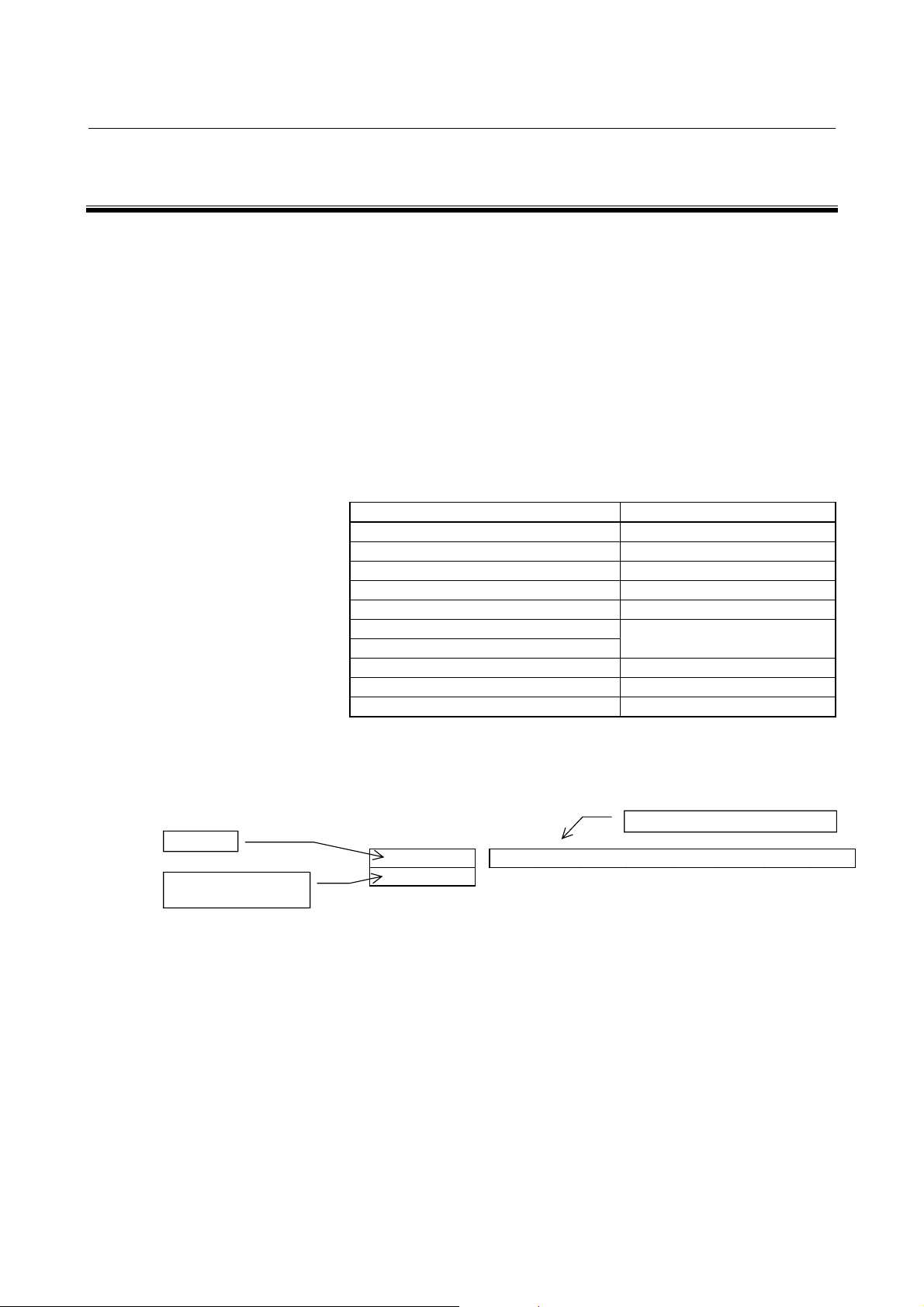
4.1.2 Check Terminal on the Printed-circuit Board
The input current check signal is output to connector JX1B. To observe
the output, use the servo check pin board A06B-6071-K290 (see
below).
Table 4.1.2(a) Check pins
Check
pin
IR
IS
0V
Description
L1 phase (R-phase)
current
L2 phase (S-phase)
current
Reference point of
observation
Table 4.1.2 (b) IR and IS current conversion value
Model Current conversion
PSM-5.5i
PSM-11i
PSM-15i
PSM-26i
PSM-30i
PSM-37i
PSM-55ii
PSM-11HVi
PSM-18HVi
PSM-30HVi
PSM-45HVi
PSM-75HVi
PSM-100HVi
Location of
observation
JX1B-pin1
JX1B-pin2
JX1Bpin12,14,16
133A/1V (2.5 V at the center)
133A/1V (2.5 V at the center)
200A/1V (2.5 V at the center)
266A/1V (2.5 V at the center)
333A/1V (2.5 V at the center)
400A/1V (2.5 V at the center)
666A/1V (2.5 V at the center)
100A/1V (2.5 V at the center)
133A/1V (2.5 V at the center)
200A/1V (2.5 V at the center)
266A/1V (2.5 V at the center)
400A/1V (2.5 V at the center)
466A/1V (2.5 V at the center)
The "+" sign with respect
to the input of the
amplifier.
If the L1 or L2 phase
current exceeds the
overcurrent alarm level,
an alarm condition (with
alarm code 01) occurs in
the PSM.
Remark
- 19 -
Page 50

4.CONFIRMATION OF THE OPERATION START-UP PROCEDURE B-65285EN/03
About the servo check pin board A06B-6071-K290
The servo check pin board can be used to observe signals in the PSM.
(1) Specification
Order specification Description Remark
A06B-6071-K290
Printed-circuit board : A20B-1005-0340
Printed-circuit board
A20B-1005-0340
Cable
A660-2042-T031#L200R0
A20B-1005-0340
<5>
<4>
<3>
<2>
<10>
<9>
<8>
<7>
<15>
<14>
<13>
<12>
<20>
<19>
<18>
<17>
CN1 CN2
100mm
Printed-circuit board with
check pins mounted
20-conductor one-to-one
cable
Length : 200mm
<1>
<6>
<11>
<16>
34mm
Cable : A660-2042-T031#L200R0
Approx. 200mm
One-to-one wiring is provided between CN1 and CN2.
The connector pin numbers correspond to the check pin numbers.
(2) Connection
Connect the cable to the connector JX1B at the front of the PSM.
PSM
A20B-1005-0340
JX1B
CN1
CN2
- 20 -
Page 51

B-65285EN/03 START-UP PROCEDURE 4.CONFIRMATION OF THE OPERATION
4.1.3 The PIL LED (Power ON Indicator) Is Off.
Table 4.1.3 Check method and action
No. Cause of trouble Check method Action
AC power for the
1
control circuit not
supplied
Blown fuse in the
2
control circuit
3
Incorrect wiring
Faulty power
supply circuit on
4
the printed circuit
board
Check that power is
connected to connector
CX1A.
Check whether F1 or F2
has blown.
See Chapter 4 of Part II.
Check whether the 24-V
power output is shortcircuited and whether a
load exceeding the rating is
connected.
The power-on LED indicator
PIL operates on the +5-V
power supply. Check the
control power voltage.
(1) If the AC power input
for control is
connected to
connector CX1B by
mistake, F2 (FU2) may
blow. Connect the AC
power input to CX1A.
(2) Replace the fuse. If
the fuse blows again
after the replacement,
replace the printed
circuit board.
Replace the printed circuit
board, driver board, or
power distribution board.
- 21 -
Page 52

4.CONFIRMATION OF THE OPERATION START-UP PROCEDURE B-65285EN/03
4.1.4 Checking Method when Magnetic Contactor Is not Switched
On
(1) The system is still in an emergency stop status.
→ Check the connection.
(2) There is a connector problem.
(a) Check that the connectors are attached to correct locations.
→ Ensure that the connectors are attached to the location
CXA2A on the PSM and the location CXA2B on the
SPM/SVM.
PSM
CXA2A
SPM/SVM
CXA2B
CXA2A
SPM/SVM
CXA2B
CXA2A
(Battery box for pulse coder)
(b) The interface cable between CXA2B of the power supply
module and CXA2A of the SVM or SPM is defective.
→ Check whether the interface cable is faulty.
(3) The power for driving the magnetic contactor is not supplied.
→ Check the voltage across the both ends of the coil of the
magnetic contactor.
(4) The relay for driving the magnetic contactor is defective.
→ Check that a circuit between pins CX3-1 and CX3-3 of
connector is closed and opened.
PSM
MCC driving relay
(5) The PSM, SVM, or SPM is defective.
→ Replace the defective module.
- 22 -
CX3-1
CX3-3
Page 53

B-65285EN/03 START-UP PROCEDURE 4.CONFIRMATION OF THE OPERATION
4.2 SERVO AMPLIFIER MODULE
Check each item according to the procedure described below.
1. Check the connection, and supply control power (200 VAC) to the power
supply module.
2. Check the STATUS LEDs. See Section 4.2.1.
Alarm occurs.
See Section 3.2 of Part II.
3. Check the CNC parameters (including servo parameters), and reset
emergency stop state.
Alarm occurs.
See Section 3.2 of Part II.
4. Check the operation of the servo motor.
Refer to the FANUC AC SERVO MOTOR
αis/αi series Parameter Manual (B-65270EN).
Abnormal operation
- 23 -
Page 54

4.CONFIRMATION OF THE OPERATION START-UP PROCEDURE B-65285EN/03
4.2.1 Checking the STATUS Display
The STATUS display (a 7-segment LED) on the front of the SVM
indicates the operation status.
Position of the
STATUS LEDs
STATUS display Description
• The STATUS display LED is not on.
<1> Power is not turned on.
<2> Poor cable connection
→ Check the cable.
<3> The servo amplifier is defective.
→ Replace the fuse (F1) or servo amplifier.
Blinking
• The cable is shorted out. Check the cable.
• The control power supply is waiting for a ready signal.
• The servo amplifier is ready to operate.
The servo motor is supplied with power.
• Alarm state
If an alarm is issued in the servo amplifier, a value
other than "0" and "-" is indicated on the STATUS
display LED. See Section 3.2 of Part II.
- 24 -
Page 55

B-65285EN/03 START-UP PROCEDURE 4.CONFIRMATION OF THE OPERATION
4.2.2 VRDY-OFF Alarm Indicated on the CNC Screen
When the VRDY-OFF alarm is indicated on the CNC, check the items
listed below. In addition, VRDY-OFF can occur also for reasons other
than listed below. If the following items turn out to have not caused
VRDY-OFF, check diagnosis information No. 358 (V ready-off
information) on the diagnosis screen and report it to FANUC.
(1) Communication interface between amplifier and module
Is the cable for the communication interface (CXA2A/B) between
the amplifier and module connected correctly?
(2) Emergency stop signal (ESP)
Has the emergency stop signal (connector: CX4) applied to the
PSM been released? Alternatively, is the signal connected
correctly?
(3) MCON signal
Hasn't setting up the axis detach function disabled the
transmission of the ready command signal MCON from the CNC
to the SVM?
(4) SVM control printed-circuit board
The SVM control printed-circuit board may be poorly installed or
faulty. Be sure to push the faceplate as far as it will go. If the
problem persist, replace the control printed-circuit board.
On the Series 16i/18i/21i/0i/PMi, checking diagnosis information
(DGN) No. 358 makes it possible to analyze the cause of the VRDYOFF alarm.
(Supported servo software: Series 90B0/D(04) and subsequent
editions)
Diagnosis
358 V ready-off information
Convert the displayed value to binary form, and check bits 5 to 14 of
the resulting binary number.
When the servo amplifier starts working, these bits become 1
sequentially, starting at bit 5. When the servo amplifier has started
normally, all of bits 5 to 14 become 1.
Check bits 5 to 14 sequentially, starting at the lowest-order bit. The
first lowest bit that is not 0 corresponds to the processing that caused
the V ready-off alarm.
#15 #14 #13 #12 #11 #10 #9 #8
SRDY DRDY INTL RLY CRDY MCOFF MCONA
#7 #6 #5 #4 #3 #2 #1 #0
MCONS *ESP HRDY
#06(*ESP) : Emergency stop signal
#07,#08,#09 : MCON signal (CNC → amplifier → converter)
#10(CRDY) : Converter preparation completed signal
#11(RLY) : Relay signal (DB relay energized)
#12(INTL) : Interlock signal (DB relay de-energized)
#13(DRDY) : Amplifier preparation completed signal
- 25 -
Page 56
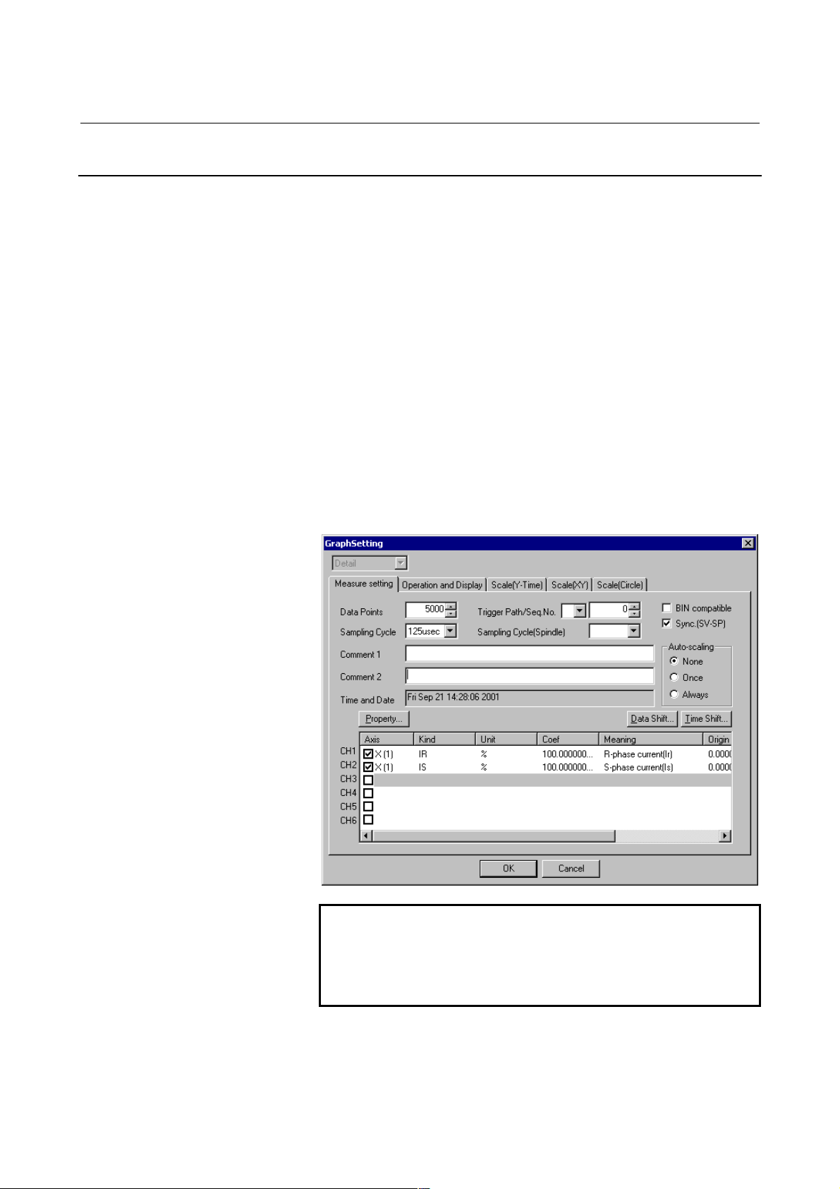
4.CONFIRMATION OF THE OPERATION START-UP PROCEDURE B-65285EN/03
4.2.3 Method for Observing Motor Current
This subsection explains how to observe the current that flows through
the servo motor.
Method of using the SERVO GUIDE
Refer to online help for explanations about how to connect to and use
the servo adjustment tool, SERVO GUIDE.
- Supported CNC systems
Series 16i/18i/21i/0i -MODEL B
Servo software supporting the αi series: Series 90B0/L(12) and
subsequent editions and 9096/C(03) and subsequent editions
- Setting
Select an axis to be subjected to measurement in graph window channel
setting. Also select IR and IS under Kind. Under Coef (conversion
coefficient), set the maximum allowable current (Ap) for the amplifier
in use.
- Display
NOTE
1 Servo software series 90B0 supports setting of a
motor current sampling period of up to 125 µs.
2 Servo software series 9096 supports setting of a
motor current sampling period of 1 ms only.
Select the XTYT mode from the graph window mode (M) menu to
display waveforms.
- 26 -
Page 57

B-65285EN/03 START-UP PROCEDURE 4.CONFIRMATION OF THE OPERATION
Method of using the servo check board
For details on how to connect and use the servo check board, refer to
the following:
Section 4.18 in the FANUC AC SERVO MOTOR αis/αi series
Parameter Manual (B-65270EN)
- Required units
- Servo check board
A06B-6057-H630
- Oscilloscope
- Settings
⋅⋅⋅⋅ CNC setting
Parameter setting for servo software series 90B0
Output channel
FS15i
FS16i/18i/21i/0i/PMi
Measurement axis/
current phase
L-axis (Note 1) 370 0 402 0
M-axis (Note 1) 2418 0 2450 0
Data number 5
No.1726 No.1774 No.1775 No.1776
No.2115 No.2151 No.2152 No.2153
IR IS
Data number 6
Parameter setting for servo software series 9096
Output channel
FS16i/18i/21i/0i/PMi
Measurement axis/
current phase
L-axis (Note 1) 370 402
M-axis (Note 1) 1010 1042
Data number 5
No.2115 No.2115
IR IS
Data number 6
When series 9096 is used, if no axis is paired with the measurement
axis (Note 2), IR and IS cannot be observed simultaneously.
NOTE
1 The L-axis is an axis identified with an odd number
set in parameter No. 1023. The M-axis is an axis
identified with an even number set in parameter No.
1023.
2 The axis specified as 2n-1 in parameter No. 1023
and the axis specified as 2n will be in a pair.
- 27 -
Page 58

4.CONFIRMATION OF THE OPERATION START-UP PROCEDURE B-65285EN/03
Setting the output period of motor current data (for the 90B0 series
only)
⋅⋅⋅⋅ Setting up the check board
Output period
Velocity loop period 0 (default)
Current loop period 1 (Note 3)
Parameter No. 1746 /
Bit 7 of parameter No. 2206
NOTE
3 If the current loop period is set up as the motor
current data output period, selecting data number 0,
1, 2, or 4 disables the output of signals (such as a
velocity command) to channels. To observe the
motor current and other signals (such as a velocity
command), specify the output period as 1 ms.
4 For the servo software series 9096, the output
period of the motor current is only 1 ms. The current
loop period cannot be used for output.
- Set the AXIS digit of the LED display with an axis number from 1
to 8 specified in parameter No. 1023.
- Set the DATA digit of the LED display with a data number from 5
to 6.
- Method for observing the motor current
The voltage corresponding to the motor current is output to a channel
for which 5
The waveform of the motor current can be observed by measuring the
voltage mentioned above with an oscilloscope.
The following table lists the relationships between the observed
voltage and the motor current.
Maximum amplifier
For the SVM1-20i, for example, the motor current is 5A (actual value
rather than effective value) if the observed voltage is 1V.
or 6 is set as the data number on the servo check board.
current
10A
20A
40A
80A
160A
180A
360A
SVM type
SVM1-10HVi and others
SVM1-20i and others
SVM1-40i and others
SVM1-80i and others
SVM1-160i and others
SVM1-180HVi and others
SVM1-360i and others
Motor current/
observed voltage
[A/V]
2.5
5
10
20
40
45
90
- 28 -
Page 59

B-65285EN/03 START-UP PROCEDURE 4.CONFIRMATION OF THE OPERATION
4.3 SPINDLE AMPLIFIER MODULE
Check each item according to the procedure described below.
1. Supply control power (200 VAC) to the power supply module, and
turn on the power to the CNC.
2. Check the STATUS display. See Subsection 4.3.1.
OK Alarm issued.
See Part II.
3. Has the system been used with this connection status?
No Yes
4. Prepare and check a PMC ladder. (The descriptions manual is
required.)
5. Set and check spindle-related parameters. (The parameter manual
is required.)
6. Check the waveform on the sensor. See Subsection 4.3.4.
7. Release the system from the emergency stop state.
8. Make sure that the magnetic contactor for PSM input is turned on.
See Section 4.1.
9. Check the operation in normal operation mode (S command).
10. Check the operation of optional functions.
- 29 -
Page 60

4.CONFIRMATION OF THE OPERATION START-UP PROCEDURE B-65285EN/03
4.3.1 STATUS Display
STATUS
ALM
ERR
No. ALM ERR STATUS Description
The control power supply has not been
switched on.
1
250
304
4
5
6 00 The motor is supplied with power.
7 Lighting
8 Lighting
No
indication
--
Blinking
--
Lighting
01 or
above is
displayed.
01 or
above is
displayed.
The power supply circuit is defective. See
Section 3.1.2.
For about 1.0 s after the control power
supply is switched on, the lower two digits of
the spindle software series No. are
indicated.
Example) 50: Software series No. 9D50
The spindle software edition number is
displayed for about 1.0 s. 01, 02, 03, and so
on correspond to A, B, C, and so on,
respectively.
Example) 04: software edition D
The CNC has not been switched on.
The machine is waiting for serial
communication and parameter loading to
end.
Parameter loading has ended.
The motor is not supplied with power.
Alarm state
The SPM is not operable.
See Chapter 1 of Part II.
Error state
Incorrect parameter setting or improper
sequence.
- 30 -
Page 61

B-65285EN/03 START-UP PROCEDURE 4.CONFIRMATION OF THE OPERATION
4.3.2 Troubleshooting at Startup
4.3.2.1 The PIL LED (power-on indicator) is off.
(1) When the PIL LED on the spindle amplifier module does not
come on after the main circuit breaker is turned on
No. Cause of trouble Check method Action
The 200-V control power is
1
not supplied.
2 The cable is defective. The PSM PIL lamp is on.
The power is externally
3
connected to 0 V, GND, or
the like.
There is a blown fuse on the
4
printed circuit board.
The printed circuit board is
5
defective.
The PSM PIL lamp is off.
When the connector is
detached, the PIL lamp is on.
Even when all cables except
the cable attached to
connector CX2A/B are
detached, the PIL lamp does
not come on.
Check the cable attached to
CX1A of PSM.
Check the cable attached to
the connector CXA2A/B.
Replace or repair the cable.
If the fuse blows, the printed
circuit board may be faulty.
Replace the unit.
Replace the unit.
- 31 -
Page 62

4.CONFIRMATION OF THE OPERATION START-UP PROCEDURE B-65285EN/03
)
4.3.2.2 The STATUS display is blinking with "--."
(1) When no spindle communication alarm message is indicated on
the CNC
Check whether the CNC software option setting or bit setting is
correct.
(2) When a communication alarm message is indicated on the CNC
No. Cause of trouble Check method Action
Note that the cable used for
1 The cable is incorrect.
2 The cable is defective.
The printed circuit board is
3
defective.
(3) When Dual Check Safety is in use, and No. 756 or 766 occurs on
the CNC (FS16i)
Check that K76, shown below, is mounted on the second spindle.
If Dual Check Safety is not in use or the CNC has only the first
spindle, K76 is unnecessary.
connecting an electric/optical
adapter and the cable
connected directly to the
CNC differ in specifications.
Check the connector housing
section.
Replace the cable with a
correct cable.
Repair or replace the cable.
Replace the unit.
CNC
Details of K76
K76
X2NDSP0V(15)
(13)
20-pin half-pitch
connector
SPM
(First spindle)
JA41 JA7B JA7A JA 7B
SPM
(Second
spindle
JA7A
K76
- 32 -
Page 63

B-65285EN/03 START-UP PROCEDURE 4.CONFIRMATION OF THE OPERATION
4.3.2.3 The motor does not turn.
(1) When "--" is indicated on the STATUS display of the SPM
Check whether spindle control signals are input. (An example for
the first spindle is shown below.)
FS15i FS16i
G227 G070 MRDYA SFRA SRVA
G226 G071 *ESPA
- G029 *SSTP
- G030 SOV7 SOV6 SOV5 SOV4 SOV3 SOV2 SOV1 SOV0
#7 #6 #5 #4 #3 #2 #1 #0
(2) When "00" is indicated on the STATUS display of the SPM
No spindle speed command is input.
Refer to Chapter 1 in "FANUC AC SPINDLE MOTOR αi series
Parameter Manual (B-65280EN)," and check related parameters.
(3) When an alarm number is indicated on the SPM
See the description of the alarm number in Part II.
4.3.2.4 A specified speed cannot be obtained.
(1) When the speed always differs from a specified speed
Check parameters.
Refer to Chapter 1 in "FANUC AC SPINDLE MOTOR αi series
Parameter Manual (B-65280EN)," and check related parameters.
(2) When an alarm number is indicated on the SPM
See the description of the alarm number in Part II.
- 33 -
Page 64

4.CONFIRMATION OF THE OPERATION START-UP PROCEDURE B-65285EN/03
4.3.2.5 When cutting is not performed, the spindle vibrates, making
noise.
(1) The spindle vibrates only when the spindle speed has reached or is
at a particular speed level.
Check whether the spindle also vibrates when the motor is turning
by inertia. If noise is unchanged, investigate the source of
mechanical vibration. There are several methods to turn the
spindle by inertia as explained below. Because these methods
involve machine sequences, consult with the machine tool
builder.
A. Setting spindle control signal MPOF (FS16i: G73#2, FS15i:
G228#2) to 1 immediately causes the spindle to turn by
inertia.
B. Set ALSP (FS16i: bit 2 of parameter No. 4009, FS15i: bit 2
of parameter No. 3009) to 1. Then, when the power to the
CNC is turned off during spindle rotation, the spindle turns
by inertia. (On the spindle amplifier, Alarm 24 is indicated.)
(2) When noise is generated at the time the motor is stopped or at any
time
A. See Subsection 4.3.4 of this part, and check and adjust the
waveform of the spindle sensor.
B. Check that the motor part number matches its parameters.
For details, refer to Appendix A in "FANUC AC SPINDLE
MOTOR αi series Parameter Manual (B-65280EN)."
C. Adjust the velocity loop gain and so forth.
For details, refer to Chapter 1 in "FANUC AC SPINDLE
MOTOR αi series Parameter Manual (B-65280EN)."
4.3.2.6 An overshoot or hunting occurs.
Refer to Chapter 1 in "FANUC AC SPINDLE MOTOR αi series
Parameter Manual (B-65280EN)," and adjust parameters.
- 34 -
Page 65

B-65285EN/03 START-UP PROCEDURE 4.CONFIRMATION OF THE OPERATION
4.3.2.7 Cutting power weakens or acceleration/deceleration slows
down.
(1) When the load meter does not indicate the maximum output
A. A mechanical cause such as a belt slip may occur.
(2) When the load meter indicates the maximum output
A. Check whether the torque limit signal is input incorrectly.
FS15i FS16i
G227 G070 TLMHA TLMLA
#7 #6 #5 #4 #3 #2 #1 #0
B. If you are using the BZi sensor, it is likely that a slip has
occurred between the sensor gear and spindle (on
acceleration).
C. Check that the motor part number matches its parameters.
For details, refer to Appendix A in "FANUC AC SPINDLE
MOTOR αi series Parameter Manual (B-65280EN)."
D. Check whether the output limit pattern is set incorrectly.
For details, refer to Chapter 1 in "FANUC AC SPINDLE
MOTOR αi series Parameter Manual (B-65280EN)."
- 35 -
Page 66

4.CONFIRMATION OF THE OPERATION START-UP PROCEDURE B-65285EN/03
A
)
4.3.3 Status Error Indication Function
When there is a sequence or parameter error, the error LED (yellow) in
the display section of the spindle amplifier module (SPM) goes on with
an error code displayed. This can ease troubleshooting at the time of
machine startup.
status
The error LED
n error code is indicated. (from 01
When the spindle amplifier module does not operate for a certain
function, check whether the status error is indicated in the display
section of the SPM.
No. Description Action
Although neither *ESP (emergency
stop signal) (there are two types of
signals, a PMC signal and PSM
contact signal) nor MRDY (machine
01
ready signal) has been input, SFR
(forward rotation signal), SRV
(reverse rotation signal), or ORCM
(orientation command) is input.
Although parameter settings are such
that that there is no position sensor
(position control is not to be
performed, that is, bits 3, 2, 1, and 0 of
parameter No. 4002 are, respectively,
03
0, 0, 0, and 0), a Cs axis contour
control command has been issued.
In this case, the motor is not
activated.
Although parameter settings are such
that that there is no position sensor
(position control is not to be
performed, that is, bits 3, 2, 1, and 0 of
parameter No. 4002 are, respectively,
0, 0, 0, and 0), a servo mode (such as
04
rigid tapping or Cs axis control)
command or spindle synchronization
control command has been issued.
In this case, the motor is not
activated.
Although optional parameter for the
orientation function is not set, an
05
ORCM (orientation command) is
input.
Although optional parameter for the
output switching option is not set,
06
low-speed winding is selected (RCH =
1).
Check the *ESP and MRDY
sequences. For MRDY, pay
attention to the parameter that
specifies whether to use the
MRDY signal (bit 0 of parameter
No. 4001).
Check setting of the parameter.
Check setting of the parameter.
Check setting of the parameter for
orientation.
Check setting of the parameter for
output switching and the power
line status signal (RCH).
- 36 -
Page 67

B-65285EN/03 START-UP PROCEDURE 4.CONFIRMATION OF THE OPERATION
No. Description Action
Although Cs contour control mode is
input, neither SFR (forward rotation
07
signal) nor SRV (reverse rotation
signal) is input.
Although servo mode (rigid tapping or
spindle positioning) control command
is input, neither SFR (forward rotation
08
signal) nor SRV (reverse rotation
signal) is input.
Although spindle synchronization
control command is input, neither
09
SFR (forward rotation signal) nor SRV
(reverse rotation signal) is input.
Although Cs contour control
command is input, another operation
mode (servo mode, spindle
10
synchronization, or orientation) is
specified.
Although servo mode (rigid tapping or
spindle positioning) is input, another
operation mode (Cs contour control,
11
spindle synchronization, or
orientation) is specified.
Although spindle synchronization is
input, another operation mode (Cs
12
contour control, servo mode, or
orientation) is specified.
Although orientation specification is
input, another operation mode (Cs
13
contour control, servo mode, or
synchronization control) is specified.
The SFR (forward rotation signal) and
14
SRV (reverse rotation signal) are
input at the same time.
Although the parameter not to use the
differential speed control function (bit
5 of parameter No. 4000 = 0) is set,
16
DEFMD (differential speed mode
command) is input.
The parameter settings for the speed
detector (bits 2, 1, and 0 of parameter
No. 4011) are invalid. There is no
17
speed detector that matches the
settings.
Check the sequence.
Check the sequence.
Check the sequence.
Do not specify another mode
during execution of the Cs contour
control command. Before entering
another mode, cancel the Cs
contour control command.
Do not specify another mode
during execution of the servo
mode command. Before entering
another mode, cancel servo
mode.
Do not specify another mode
during execution of the spindle
synchronization command. Before
entering another mode, cancel the
spindle synchronization
command.
Do not specify another mode
during execution of the orientation
command. Before entering
another mode, cancel the
orientation command.
Input one of the SFR and SRV
signals.
Check the setting of the
parameter and the differential
speed mode command.
Check the setting of the
parameter.
- 37 -
Page 68

4.CONFIRMATION OF THE OPERATION START-UP PROCEDURE B-65285EN/03
No. Description Action
Although parameter settings are such
that that there is no position sensor
(position control is not to be
performed, that is, "bits 3, 2, 1, and 0
18
of parameter No. 4002 are,
respectively, 0, 0, 0, and 0," a position
coder-based orientation command
has been issued.
Although magnetic sensor orientation
command is input, another operation
mode (Cs contour control, servo
19
mode, or spindle synchronization) is
specified.
Although continuous indexing in
position coder-based orientation is to
be performed, an absolute position
24
command (INCMD = 0) has been
issued after incremental operation
(INCMD = 1).
Parameter settings are such that the
shortest-time orientation function is to
be used (bit 6 of parameter No. 4018
29
is 0 and parameter Nos. 4320 to 4323
are nonzero).
This hardware configuration does not
support the use of the spindle FAD
31
function. In this case, the motor is not
activated.
This hardware configuration does not
support the use of the spindle EGB
33
function. In this case, the motor is not
activated.
Both spindle FAD function and
34
spindle EGB function are enabled. In
this case, the motor is not activated.
Check the setting of the
parameter and the input signal.
Do not specify another mode
during execution of the orientation
command. Before entering
another mode, cancel the
orientation command.
Check the INCMD (incremental
command).
Be sure to perform absolute
position command-based
orientation before an absolute
position command.
The shortest-time orientation
function cannot be used in the αi
series spindle amplifier. Use a
different type of orientation.
Check the CNC model.
Check the CNC model.
These functions cannot be used at
the same time. Enable only one of
the functions.
- 38 -
Page 69

B-65285EN/03 START-UP PROCEDURE 4.CONFIRMATION OF THE OPERATION
4.3.4 Checking the Feedback Signal Waveform
The measurement locations and the method for attaching connectors
vary depending on the configuration of the detector. Check the
waveform while seeing Table 4.3.4. The check terminals are on the
check board.
Table 4.3.4(a) Signals input to the SPM and corresponding check terminals on the check board
Check
terminal
name
PA1
PB1
PA2
PB2
PS1
PS2
EXTSC1
SPM input signal
(connector
name-pin No.)
JYA2-pin5,6
JYA2-pin7,8
JYA4-pin5,6
JYA4-pin7,8
JYA2-pin1,2
JYA4-pin1,2
JYA3-pin15 Proximity switch (external one-rotation signal)
Mi, MZi, and BZi sensors
Mi, MZi, and BZi sensors
α position coder S (1024λ)
MZi and BZi sensors (one-rotation signal)
MZi and BZi sensors (one-rotation signal)
Main sensors Remarks
For the α position coder and α position coder S (one-rotation signal),
observe the SPM input signal directly, using the servo check pin board
A06B-6071-K290.
For TYPE B only
For TYPE B only
- 39 -
Page 70

4.CONFIRMATION OF THE OPERATION START-UP PROCEDURE B-65285EN/03
A
4.3.4.1 Mi, MZi, and BZi sensors
Measurement
location
PA1, PB1
Separate sensors
PA2, PB2
Measurement
condition
The speed must be
1500 min
-1
or less.
Rotation direction: CW
Detection gear
Motor
CW
Waveforms of phase
and phase B
Ripples of phase A and
phase B
For MZi and BZi sensors only
Waveform of
phase Z
Sample waveform
PA1 (PA2)
Voffs
PB1 (PB2)
0 V
PA1, PB1 (PA2, PB2)
(Z - *Z)
Vpp
Vphase
Vrip
Vpz
Voffz
0 V
Measurement item Specification Measurement method Adjustment method
Vpp 0.5 to 1.2 Vp-p
Voffs, Voffsz 2.5 V ±100 mV
Vphase 90 ±3°
Vrip < 70 mV
Use the DC range of a digital
voltmeter.
Normally, the Mi and MZi sensors
need not be adjusted. For Voffs and
Voffz, only level check is possible,
but adjustment is not possible.
Vpz > 0.5 V
- 40 -
Page 71

B-65285EN/03 START-UP PROCEDURE 4.CONFIRMATION OF THE OPERATION
A
4.3.4.2 α
Measurement
location
α position coder S
αα
Measurement
condition
PA2, PB2 CW rotation direction as
viewed from the flange
Waveforms of phase
and phase B
Waveform of phase
Z
Sample waveform
PA1 (PA2)
Voffs
PB1 (PB2)
0 V
(Z - *Z)
Vpp
Vphase
0V
Measurement item Specification Measurement method Adjustment method
Vpp 0.8 to 1.2 Vp-p
Voffs,Voffsz 2.5 V ±100 mV
Use the DC range of a digital
voltmeter.
Only level check is possible, but
adjustment is not possible.
Vphase 90 ±5°
- 41 -
Page 72

4.CONFIRMATION OF THE OPERATION START-UP PROCEDURE B-65285EN/03
4.3.5 Spindle Check Board
When connecting the check board, you can:
<1> Observe signal waveforms.
<2> Observe internal data.
<3> Check spindle parameter values.
4.3.5.1 Spindle check board specifications
Spindle check board specifications is bellow.
Table 4.3.5.1 Spindle check board specifications
Specification
A06B-6078-H001 A20B-2001-0830
4.3.5.2 Check board connection
Drawing No. of printed
circuit board
αi series, αCi series
(having the same specification as
for the α series)
Applicable unit
(1) αi series
SPM
JX4
JY1
JY1A JX4A
A20B-2001-0830
JY1B JX4B
Spindle check board
Output equivalent to JX4
Output equivalent to JY1
- 42 -
Page 73

B-65285EN/03 START-UP PROCEDURE 4.CONFIRMATION OF THE OPERATION
(2) αCi series
SPMC
JY1
JY1A JX4A
A20B-2001-0830
JY1B JX4B
Output equivalent to JY1
Spindle
check
board
- 43 -
Page 74

4.CONFIRMATION OF THE OPERATION START-UP PROCEDURE B-65285EN/03
4.3.5.3 Check terminal output signals
(1) αi series
Check terminal Signal name Check terminal Signal name
LM Load meter signal PA1 Phase A sine wave signal 1
SM Speedometer signal PB1 Phase B sine wave signal 1
Analog output for internal data
CH1
CH2
CH1D Output for internal data bit observation PB2 Phase B sine wave signal 2 (TYPE B)
CH2D Output for internal data bit observation PS2 Phase Z sine wave signal 2 (TYPE B)
VRM Disuse PA3 Disuse
LSA1 Disuse PB3 Disuse
EXTSC1 External one-rotation signal (main) PA4 Disuse
LSA2 Disuse PB4 Disuse
EXTSC2 Disuse OVR2 Analog override command
PAD
PBD
PSD
observation
(Phase U current: IU)
Analog output for internal data
observation
(Motor speed TSA: 1638 min
Phase A of position coder signal output
(TYPE B)
Phase B of position coder signal output
(TYPE B)
Phase Z of position coder signal output
(TYPE B)
-1
/V)
PS1 Phase Z sine wave signal 1
PA2 Phase A sine wave signal 2 (TYPE B)
15V Disuse
5V +5 VDC power check
-15V Disuse
GND 0 V
(2) αCi series
Check terminal Signal name Check terminal Signal name
Speedometer signal (This can be
LM
SM Disuse PB1 Disuse
CH1
CH2
CH1D Output for internal data bit observation PB2 Disuse
CH2D Output for internal data bit observation PS2 Disuse
VRM Disuse PA3 Disuse
LSA1 Disuse PB3 Disuse
EXTSC1 Disuse PA4 Disuse
LSA2 Disuse PB4 Disuse
EXTSC2 Disuse OVR2 Analog override command
PAD Disuse 15V Disuse
PBD Disuse 5V +5 VDC power check
PSD Disuse -15V Disuse
switched to the load meter signal by
parameter setting.)
Analog output for internal data
observation
(Phase U current: IU)
Analog output for internal data
observation
(Estimated motor speed : 1638 min
PA1 Disuse
PS1 Disuse
-1
/V)
PA2 Disuse
GND 0 V
- 44 -
Page 75

B-65285EN/03 START-UP PROCEDURE 4.CONFIRMATION OF THE OPERATION
Check terminal arrangement
PIL
LM
SM
VRM
0V
PA2
PB2
PS2
0V
LSA2
EXTSC2
PAD
PBD
PSD
5V
15V
-15V
Display
Operation
buttons
DATA
SET
UPMODE
DOWN
CH1
LSA1
CH1D
EXTSC1
CH2
CH2D
0V
PA3
PA1
PB3
PB1
PA4
PS1
PB4
0V
OVR2
- 45 -
Page 76

4.CONFIRMATION OF THE OPERATION START-UP PROCEDURE B-65285EN/03
4.3.6 Observing Data Using the Spindle Check Board
4.3.6.1 Overview
By using the check board, you can convert digital signals used for
control in the spindle amplifier module to analog voltage, and observe
the conversion result with an oscilloscope. For internal data
observation, you can use CH1 and CH2 (output: -5 to +5 V) as the
two-channel analog output, and CH1D and CH2D as the output for
checking specific bits of bit data or the like. You can also view internal
data on the five-digit indicator.
4.3.6.2 Major characteristics
Item
Measurement point CH1, CH2 CH1D, CH2D
Output voltage range -5 to +5 V
Resolution
Output impedance 10 kΩmin 10 kΩmin
About 39 mV
(10 V/256)
H: 2 Vmin
L: 0.8 Vmax
-
4.3.6.3 Observation method
By setting data using four DIP switches on the check board, you can
output internal data to the five-digit display, analog voltage output
circuit, channels 1 and 2 (LM and SM or CH1 and CH2).
Data on channels 1 and 2 is the one from an 8-bit D/A convertor.
The correspondence between channel 1/2 and the check terminal is
listed below.
Channel 1
Channel 2
Measurement point Check terminal
CH1
CH1D, data bit 0
CH2
CH2D, data bit 0
- 46 -
Page 77

B-65285EN/03 START-UP PROCEDURE 4.CONFIRMATION OF THE OPERATION
4.3.6.4 Specifying data to be monitored
<1> Press the four setting switches at the same time for at least a
second ."FFFFF" will be displayed on the indicator.
<2> Turn off the switches and press the "MODE" switch. "d-00" will
be displayed on the indicator and the system will enter the mode
for monitoring internal data.
<3> In this mode, the motor can be operated normally.
Press the "UP" or "DOWN" switch while holding down the
"MODE" switch. The indicator display will change in the range of
"d-00" to "d-12".
<4> The following shows the correspondence between the
destinations of the internal data of the serial spindle and addresses
d-01 to d-12.
d-01 to d-04: Specifies the amount of data to be output to the
indicator, data shift, and output format (decimal
or hexadecimal).
d-05 to d-08: Specifies the amount of data to be output to the
channel 1, data shift, and whether an offset is
provided.
d-09 to d-12: Specifies the amount of data to be output to the
channel 2, data shift, and whether an offset is
provided.
<5> Select address d-xx in the procedure for setting data described in
<3>.
<6> Turn off the "MODE" switch. "d-xx" will disappear 0.5 second
later, and the data will be displayed for a second.
Change the set data using the "UP" or "DOWN" switch within the
second the data is displayed.
<7> When more than a second elapses without pressing the "UP" or
"DOWN" switch, data cannot be changed.
If the "MODE" switch is turned on or off, however, setting can be
started from the beginning of the step in item <6>.
- 47 -
Page 78

4.CONFIRMATION OF THE OPERATION START-UP PROCEDURE B-65285EN/03
4.3.6.5 Address descriptions and initial values (SPM)
[Output to the indicator]
Address Description Initial value
d-01 Specifies a data number. 0
d-02 Shift at data output (0 to 31 bits) 0
Data shift direction
d-03
d-04
[Output to the channel 1]
Address Description Initial value
d-05 Specifies a data number
d-06
d-07
d-08
0 : Data is shifted right.
1 : Data is shifted left.
Display format
0 : Decimal notation
1 : Hexadecimal notation(0 to F)
Shift at data output
(0 to 31 bits)
Data shift direction
0: Data is shifted right
1: Data is shifted left
Offset
0: Not provided
1: Provided
0
0
218
(U-phase current)
8
0
1
[Output to the channel 2]
Address Description Initial value
d-09 Specifies a data number
d-10
d-11
d-12
Shift at data output
(0 to 31 bits)
Data shift direction
0: Data is shifted right
1: Data is shifted left
Offset
0: Not provided
1: Provided
19
(Motor velocity)
18
0
1
- 48 -
Page 79

B-65285EN/03 START-UP PROCEDURE 4.CONFIRMATION OF THE OPERATION
4.3.6.6 Principles in outputting the internal data of the serial spindle
The length of data is 32 bits (BIT31 TO BIT00) unless it is described as
16 bits.
BIT31 BIT00BIT01BIT02BIT03
(1) Example of output to the indicator
Example1 Displaying data in decimal
When the number of digits to shift data (d-02)=0 and display format
(d-04)=0 (decimal notation): The last 16 bits of data (BIT15 to BIT00)
are converted into decimal (0 to 65535 max.) and displayed.
BIT15 BIT00BIT01
Indicator
Example2 Displaying data in hexadecimal
When the number of digits to shift data (d-02)=0 and display format
(d-04)=1 (hexadecimal notation): The last 16 bits of data (BIT15 to
BIT00) are converted into hexadecimal (0 to FFFFF max.) and
displayed.
BIT15 BIT00BIT01
……
……
16 bits
Converted into decimal
data and displayed
X X X X X
……
16 bits
Converted into hexadecimal
data and displayed
Indicator
X X X X
(The fifth digit is bl ank.)
Example3 Shifting data left
When the number of digits to shift data (d-02)=3, the shift direction is
left (d-03=1), and display format (d-04)=1 (hexadecimal notation):
Data in BIT12 to BIT00 and the last three bits of data (=0) are
converted into hexadecimal (0 to FFFFF max.) and displayed.
Indicator
……
16 bits
Converted into hexadecimal
data and displayed
X X X X
000BIT00BIT01
(The fifth digit is bl ank.)
BIT12
- 49 -
Page 80

4.CONFIRMATION OF THE OPERATION START-UP PROCEDURE B-65285EN/03
Example4 Shifting data right
When the number of digits to shift data (d-02)=5, shift direction is right
(d-03=0), and display format (d-04)=0 (decimal notation): Data in
BIT20 to BIT05 is converted into decimal (0 to 65535 max.) and
displayed.
BIT20 BIT05BIT06
Indicator
……
16 bits
Converted into decimal
data and displayed
X X X X X
Example5 Shifting data right when the data length is 16 bits
When the data length is 16 bits, data shift (d-02)=5, shift direction is
right (d-03=0), and display format is decimal notation (d-04=0): The
first five bits of data and data in BIT15 to BIT05 are converted into
decimal and displayed.
000 BIT050 0
Indicator
BIT15
16 bits
X X X X X
……
Converted into decimal
data and displayed
- 50 -
Page 81

B-65285EN/03 START-UP PROCEDURE 4.CONFIRMATION OF THE OPERATION
(2) Example of output to the channel 1
Internal data is output to channel 1 by setting it in an 8-bit D/A
convertor.
The D/A converter output ranges from -5 to +5 V, depending on a
set value of internal data. See the table below.
Internal data in binary
(decimal)
00000000 (0) 0 -5V
11111111 (255) 0 +4.96V
10000000 (-128) 1 -5V
00000000 (0) 1 0V
01111111 ( 127) 1 +4.96V
Setting d-08
(whether there is offset)
Output on channel 1
Example1 Data set
When the number of digits to shift data (d-06)=0 and when no offset is
provided (d-08=0): The last eight bits of data (BIT07 to BIT00) is set in
the D/A converter of the LM terminal.
BIT07 BIT00BIT01
BIT06 BIT05 BIT04 BIT03 BIT02
Set in the D/A converter for channel 1 output
Example2 Shifting data left
When the number of digits to shift data (d-06)=3, shift direction is right
(d-07=1), and no offset is provided (d-08=0): Data in BIT14 to BIT00
and the last three bits of data (=0) are set in the D/A converter.
BIT04 00
BIT03 BIT02 BIT01 BIT00 0
Set in the D/A converter for channel 1 output
Example3 Shifting data right
When the number of digits to shift data (d-06)=10, shift direction is
right (d-07=1), and no offset is provided (d-08=0): Data in BIT17 to
BIT10 is set in the D/A converter.
BIT17 BIT10BIT11
BIT16 BIT15 BIT14 BIT13 BIT12
Set in the D/A converter for channel 1 output
- 51 -
Page 82

4.CONFIRMATION OF THE OPERATION START-UP PROCEDURE B-65285EN/03
Example4 Shifting data right when the data length is 16 bits
When the data length is 16 bits, data shift (d-06)=10, shift direction is
right (d-07=0), and no offset is provided (d-08=0): The first two bits of
data (=0) and data in BIT15 to BIT10 are set in the D/A converter.
0 BIT10BIT11
0 BIT15 BIT14 BIT13 BIT12
Set in the D/A converter for channel 1 output
Example5 If an offset is provided
When the number of digits to shift data (d-06)=10, shift direction is
right (d-07=0), and an offset is provided (d-08=1): Data in most
significant bit BIT17 (to which 1 is added) and data in BIT16 to BIT10
are set in the D/A converter.
BIT17 Data +1 BIT10BIT11BIT16 BIT15 BIT14 BIT13 BIT12
Set in the D/A converter for channel 1 output
Example6 Data bit observation
For data shift (d-06) = 0 with no offset (d-08 = 0), the lowest data bit
(BIT00) can be observed as a high/low level at check terminal CH1D.
BIT07
BIT06 BIT05 BIT04 BIT03 BIT02
(3) Example of output to the channel 2
Output to the channel 2 is the same as that to the channel 1.
However, the addresses for setting data (d-09 to d-12) are
different from those for output to the channel 1.
Setting velocity information in the channel 1 and the number of
errors in the channel 2 enables simultaneous monitoring of the
change in each data item using the two channels.
BIT01
BIT00
Output to check terminal CH1D
- 52 -
Page 83

B-65285EN/03 START-UP PROCEDURE 4.CONFIRMATION OF THE OPERATION
4.3.6.7 Data numbers
(1) Data numbers
Data
No.
Main data
16 Motor speed command 32
19 Motor speed 32
25 Motor speed deviation 32
4 Move command 32
9 Positioning error 32
90 Torque command 16 0 to ±16384
131 Speedometer data 16 SM terminal
132 Load meter data 16 LM terminal
136 Position error 32
Data between the spindle and CNC
5 Speed command data 16
6 Spindle control signal 1 16
10 Load meter data 16 +32767 for maximum output
11 Motor speed data 16 ±16384 for maximum speed
12 Spindle status signal 1 16
66 Spindle control signal 2 16
182 Spindle status signal 2 16
Other data
218
219
162 DC link voltage 16 1000 V/FS by shifting 8 bits left
Description
Phase U current (A/D
conversion data)
Phase V current (A/D
conversion data)
Data
length
The 12th bit (BIT12) indicates a units
-1
in min
The 12th bit (BIT12) indicates a units
-1
in min
for the αCi series.)
(Speed command - motor speed) The
12th bit (BIT12) indicates a units in
-1
.
min
Number of command pulses for ITP
(usually 8 ms)
Number of erroneous pulses (Spindle
synchronous control, Cs contour
control, Rigid tapping mode)
Number of erroneous pulses (Position
coder orientation)
±16384 for the maximum speed
command
See the command signal from the
PMC to spindle in (3).
See the status signal from the spindle
to PMC in (3).
See the command signal from the
PMC to spindle in (3).
See the status signal from the spindle
to PMC in (3).
16 10 V/FS by shifting 8 bits left
16
Remarks
.
. (An estimated value is used
- 53 -
Page 84

4.CONFIRMATION OF THE OPERATION START-UP PROCEDURE B-65285EN/03
(2) Internal data conversion
Data No. Signal name
218 IU Phase U current
219 IV Phase V current
162 VDC
*1 Current conversion result for channels 218 and 219
Description (All are voltage values on check pins
when the shift amount is 8.)
The current is positive when it is
input to the amplifier. (*1)
DC link voltage signal
100V/1V (200 V system)
200V/1V (400 V system)
Model Conversion result
SPM-2.2i
SPM-5.5i
SPM-11i
SPM-15i
SPM-22i
SPM-26i
SPM-30i
SPM-45i
SPM-55i
SPM-5.5HVi
SPM-11HVi
SPM-15HVi
SPM-30HVi
SPM-45HVi
SPM-75HVi
SPM-100HVi
16.7A/1V
33.3A/1V
50.0A/1V
66.7A/1V
100A/1V
133A/1V
150A/1V
233A/1V
16.7A/1V
33.3A/1V
50.0A/1V
66.7A/1V
133A/1V
150A/1V
(3) About the spindle control and spindle status signals
Shown below are the data numbers for the PMC signals used by
the spindle and the configuration of each data item. Refer to
Chapter 3, "PMC Signals (CNC ↔ PMC)" of "FANUC AC
SPINDLE MOTOR αi series PARAMETER MANUAL" (B65280EN) for explanations about each signal.
(a) Data number 6 : Spindle control signal 1
#15 #14 #13 #12 #11 #10 #9 #8
RCH RSL INTG SOCN MCFN SPSL *ESP ARST
#7 #6 #5 #4 #3 #2 #1 #0
MRDY ORCM SFR SRV CTH1 CTH2 TLMH TLML
(b) Data number 66 : Spindle control signal 2
#15 #14 #13 #12 #11 #10 #9 #8
DSCN SORSL MPOF
#7 #6 #5 #4 #3 #2 #1 #0
RCHHG MFNHG INCMD OVR NRRO ROTA INDX
- 54 -
Page 85

B-65285EN/03 START-UP PROCEDURE 4.CONFIRMATION OF THE OPERATION
(c) Data number 12 : Spindle status signal 1
#15 #14 #13 #12 #11 #10 #9 #8
RCFN RCHP CFIN CHP
#7 #6 #5 #4 #3 #2 #1 #0
ORAR TLM LDT2 LD T1 SAR SDT SST ALM
(d) Data number 182 : Spindle status signal 2
#15 #14 #13 #12 #11 #10 #9 #8
#7 #6 #5 #4 #3 #2 #1 #0
EXOF SOREN INCST PC1DT
- 55 -
Page 86

4.CONFIRMATION OF THE OPERATION START-UP PROCEDURE B-65285EN/03
4.3.6.8 Example of observing data
(1) Example of observing a positioning error using the channel 1
Address Description Set Data
d-05 Data number 9 9 9 9
d-06 Data shift 0 1 1 2
d-07 Data shift direction 0 1 1 1
d-08 Offset 1 1 1 1
Data unit (NOTE) 256p/FS 512p/FS 128p/FS 64p/FS
NOTE
FS=10V (-5V to 5V)
(2) Example of observing a motor speed using the channel 2
Address Description Set Data
d-09 Data number 19 19 19
d-10 Data shift 12 13 11
d-11 Data shift direction 0 0 0
d-12 Offset 0 0 0
Data unit (NOTE) 256min-1/FS 512min-1/FS 128 min-1/FS
NOTE
FS=10V (-5V to 5V)
(3) Observation of phase U current in the SPM-11i
Setting of observation data
Data No. 218
Shift amount 8
Shift direction 0 (shifted left)
Offset 1 (provided)
+5 V
100 A
0 V
-5 V
33.3 A/1 V
- 56 -
Page 87

B-65285EN/03 START-UP PROCEDURE 4.CONFIRMATION OF THE OPERATION
4.3.7 Checking Parameters Using the Spindle Check Board
4.3.7.1 Overview
By using the check board, you can check parameter values transferred
to the spindle amplifier module. Specify parameter numbers using the
four setting switches on the check board, and check parameter values
on the five-digit indicator.
4.3.7.2 Checking parameters
<1> Press the four setting switches at the same time for at least one
second. "FFFFF" will be displayed on the indicator.
<2> Turn off the switches and press the "MODE" switch. "d-00" will
be displayed on the indicator and the system will enter the mode
for measuring internal data.
<3> With "0" set for "d-00", press the "MODE" and "DATA SET"
switches at the same time for at least one second. "CCCCC" will
be displayed on the indicator.
<4> Turn off the switches and press the "MODE" switch. "F-xxx" will
be displayed on the indicator and the system will enter the mode
for checking spindle parameters (F-mode). (Even in this mode, the
motor can be operated normally.)
<5> Press the "UP" or "DOWN" switch while holding down the
"MODE" switch (with "F-xxx" displayed). The number of "Fxxx" increases or decreases. Set the internal number of a
parameter you want to check. For correspondences between the
parameter internal numbers and NC parameter numbers, see the
parameter list in the appendix to the parameter manual.
<6> Turn off the switches. The parameter value corresponding to the
set internal number is displayed for about one second. (Bit
parameter values are displayed in hexadecimal.)
- 57 -
Page 88

4.CONFIRMATION OF THE OPERATION START-UP PROCEDURE B-65285EN/03
4.3.8 Observing Data Using the SERVO GUIDE
4.3.8.1 Overview
Using the servo adjustment tool, SERVO GUIDE, enables you to
observe internal data for the spindle.
This subsection describes the spindle data that can be observed using
the SERVO GUIDE. It also presents examples of observed data. Refer
to online help for detailed explanations about how to use the SERVO
GUIDE.
4.3.8.2 Usable series and editions
Series 9D50/B(02) and subsequent editions
4.3.8.3 List of spindle data that can be observed using the SERVO
GUIDE
The following table lists the spindle data that can be observed using the
SERVO GUIDE.
Data type Description
SPEED Motor speed
INORM Motor current amplitude
TCMD Torque command
VCMD Motor speed command
VERR Speed deviation
WMDAT Move command for an individual position loop
PERR1 Position error 1
ORERR Position error at orientation
PCPOS Cumulative position feedback value
MCMD Move command for an individual communication cycle
PERR2 Position error 2
CSPOS Cumulative position feedback value
SPCMD Speed command data from the CNC
SPCT1 Spindle control signal 1
SPCT2 Spindle control signal 2
SPST1 Spindle status signal 1
SPST2 Spindle status signal 2
ORSEQ Orientation sequence data
- 58 -
Page 89

B-65285EN/03 START-UP PROCEDURE 4.CONFIRMATION OF THE OPERATION
4.3.8.4 About the spindle control and spindle status signals
As stated in the previous item, the SERVO GUIDE can be used to
observe the PMC signals (spindle control signals 1 and 2 and spindle
status signals 1 and 2) used by the spindle.
Listed below is the data configuration for spindle control signals 1 and
2 and spindle status signals 1 and 2. Refer to Chapter 3, "PMC Signals
(CNC ↔ PMC)" of "FANUC AC SPINDLE MOTOR αi series
PARAMETER MANUAL" (B-65280EN) for explanations about each
signal.
(a) Spindle control signal 1 (SPCT1)
#15 #14 #13 #12 #11 #10 #9 #8
RCH RSL INTG SOCN MCFN SPSL *ESP ARST
#7 #6 #5 #4 #3 #2 #1 #0
MRDY ORCM SFR SRV CTH1 CTH2 TLMH TLML
(b) Spindle control signal 2 (SPCT2)
#15 #14 #13 #12 #11 #10 #9 #8
DSCN SORSL MPOF
#7 #6 #5 #4 #3 #2 #1 #0
RCHHG MFNHG INCMD OVR NRRO ROTA INDX
(c) Spindle status signal 1 (SPST1)
#15 #14 #13 #12 #11 #10 #9 #8
RCFN RCHP CFIN CHP
#7 #6 #5 #4 #3 #2 #1 #0
ORAR TLM LDT2 LD T1 SAR SDT SST ALM
(d) Spindle status signal 2 (SPST2)
#15 #14 #13 #12 #11 #10 #9 #8
#7 #6 #5 #4 #3 #2 #1 #0
EXOF SOREN INCST PC1DT
- 59 -
Page 90

4.CONFIRMATION OF THE OPERATION START-UP PROCEDURE B-65285EN/03
4.3.8.5 Example of observing data
The following figure shows an example of data (synchronization error
and motor speed at rigid tapping) observed using the SERVO GUIDE.
DRAW1 : SYNC
DRAW2 : SPEED
DRAW1 : SYNC (synchronization error) *1
DRAW2 : SPEED (motor speed)
*1 The synchronization error is servo axis output data.
- 60 -
Page 91

B-65285EN/03 START-UP PROCEDURE 5.PERIODIC MAINTENANCE OF SERVO AMPLIFIER
5 PERIODIC MAINTENANCE OF SERVO
AMPLIFIER
- 61 -
Page 92

5.PERIODIC MAINTENANCE OF SERVO AMPLIFIER START-UP PROCEDURE B-65285EN/03
5.1 BATTERY FOR THE ABSOLUTE PULSECODER
The battery unit for the absolute Pulsecoder can be connected using
[Connection scheme 1] and [Connection scheme 2] explained below.
Refer to Subsection 9.3.2.6, "Battery" in "FANUC SERVO
AMPLIFIER αi series Descriptions (B-63282EN)" for details.
[Connection scheme 1]
Supplying power from one battery unit to more than one SVM
Battery case
A06B-6050-K060
PSM
CXA2A
SVM SVM
CXA2B CXA2B
CXA2A CXA2A
Battery
A06B-6050-K061
Connector
A06B-6110-K211
- If a low battery voltage or a battery voltage of 0 V is indicated by
an APC (absolute Pulsecoder) alarm, replace the battery.
If a battery voltage of 0 V is indicated, you need to make a zero
point return.
- The absolute Pulsecoder of the αis/αi series servo motor is
incorporated with a backup capacitor as standard. This backup
capacitor enables an absolute position detection to be continued
for about 10 minutes. Therefore, no zero point return need be
performed if the time during which servo amplifier power is kept
off for battery replacement is within 10 minutes.
On the contrary, the absolute Pulsecoder of the standard α series
servo motor is not incorporated with a backup capacitor. Be
careful when replacing the battery for this Pulsecoder. See
[Caution No. 1 for battery replacement] at the end of this section
for details.
- The service life of the batteries is about two years if they are used
in a six-axis configuration with αis/αi series servo motors and one
year if they are used in a six-axis configuration with α series servo
motors.
FANUC recommends that you replace the batteries periodically
according to the battery service life.
- The battery unit consists of four R20 alkaline batteries.
Commercial batteries can be used in the battery unit. The optional
battery offered by FANUC is A06B-6050-K061.
- 62 -
Page 93

B-65285EN/03 START-UP PROCEDURE 5.PERIODIC MAINTENANCE OF SERVO AMPLIFIER
WARNING
1 Do not connect more than one battery to the same
BATL (B3) line. If the output voltage is different
between the batteries, they may be short-circuited,
resulting in the batteries becoming very hot.
2 Install the battery with correct polarity. If the battery is
installed with incorrect polarity, it may overheat, blow
out, or catch fire.
- 63 -
Page 94

5.PERIODIC MAINTENANCE OF SERVO AMPLIFIER START-UP PROCEDURE B-65285EN/03
[Connection scheme 2] Incorporating each SVM with batteries
SVM
Battery case
A06B-6114-K500
Battery
A06B-6073-K001
CX5X
SVM
Battery case
A06B-6114-K500
Battery
A06B-6073-K001
CX5X
- If a low battery voltage or a battery voltage of 0 V is indicated by
an APC (absolute Pulsecoder) alarm, replace the battery (A06B6073-K001).
If a battery voltage of 0 V is indicated, you need to make a zero
point return.
- The absolute Pulsecoder of the αis/αi series servo motor is
incorporated with a backup capacitor as standard. This backup
capacitor enables an absolute position detection to be continued
for about 10 minutes. Therefore, no zero point return need be
performed if the time during which servo amplifier power is kept
off for battery replacement is within 10 minutes.
On the contrary, the absolute Pulsecoder of the standard α series
servo motor is not incorporated with a backup capacitor. Be
careful when replacing the battery for this Pulsecoder. See
[Caution No. 1 for battery replacement] at the end of this section
for details.
- The service life of the batteries is about two years with αis/αi
series servo motors and one year with α series servo motors.
FANUC recommends that you replace the batteries periodically
according to the battery service life.
- The built-in batteries are not commercially available. They must
be purchased from FANUC. So, FANUC recommends that you
keep spares.
- 64 -
Page 95

B-65285EN/03 START-UP PROCEDURE 5.PERIODIC MAINTENANCE OF SERVO AMPLIFIER
WARNING
1 When using the built-in batteries (A06B-6073-
K001), do not connect them to the BATL (B3) of
connector CXA2A/CXA2B.
The output voltages from different SVM batteries
may be short-circuited, resulting in the batteries
becoming very hot.
2 Do not connect more than one battery to the same
BATL (B3) line. If the output voltage is different
between the batteries, they may be short-circuited,
resulting in the batteries becoming very hot.
3 Install the battery with correct polarity. If the battery
is installed with incorrect polarity, it may overheat,
blow out, or catch fire.
[Installation procedure for the battery]
(1) Remove the battery cover from the SVM.
(2) Install the battery in the SVM as shown in the figure below.
(3) Install the battery cover.
(4) Attach the battery connector to CX5X of the SVM.
SVM
Inserting direction
Connector
CX5X
+6 V
0 V
Battery
Battery cover
CAUTION
1 When the battery is installed in the SVM from the
side from which the cable is drawn, the cable may
be stretched tight, which can lead to a poor contact
condition. Therefore, install the battery so that the
cable is not extended tightly.
2 Be careful when handling the connector. See
[Caution No. 2 for battery replacement] at the end of
this section for details.
Cable side
Red: +6 V
Black: 0 V
- 65 -
Page 96

5.PERIODIC MAINTENANCE OF SERVO AMPLIFIER START-UP PROCEDURE B-65285EN/03
[Caution No. 1 for battery replacement]
The Pulsecoder for the α series servo motor is not incorporated with a
backup capacitor as standard. To keep the absolute position
information in the absolute Pulsecoder, you need to keep the control
power turned on during battery replacement. Follow the procedure
explained below.
[Replacing procedure for the battery]
1. Make sure that the power to the SVM is on (the 7-segment LED
on the front of the SVM is on).
2. Make sure that the emergency stop button of the system has been
pressed.
3. Make sure that the motor is not activated.
4. Make sure that the DC link charge LED of the SVM is off.
5. Remove the old battery, and install a new battery.
6. This completes the replacement. You can turn off the power to the
system.
WARNING
1 When replacing the battery, be careful not to touch
bare metal parts in the panel. In particular, be
careful not to touch any high-voltage circuits due to
the electric shock hazard.
2 Before replacing the battery, check that the DC link
charge confirmation LED on the front of the servo
amplifier is off. Neglecting this check creates an
electric shock hazard.
3 Install the battery with correct polarity. If the battery
is installed with incorrect polarity, it may overheat,
blow out, or catch fire.
4 Avoid a short-circuit between the +6 V and 0 V lines
of a battery or cable. A short-circuit may lead to a
hot battery, an explosion, or fire.
- 66 -
Page 97

B-65285EN/03 START-UP PROCEDURE 5.PERIODIC MAINTENANCE OF SERVO AMPLIFIER
[Caution No. 2 for battery replacement]
If an excessive strain is applied to a connector when it is inserted or
removed, a poor contact may result. When inserting and removing the
battery connector, therefore, be careful not to apply an excessive
wrenching force to it; just follow the instructions given in the following
table.
(1) Attaching connectors
<1>
<2>
<5>
<3>
<4>
10 degrees or less
5 degrees or less
Check the attachment
position.
Plug the cable
connector while
raising it slightly.
Here, the angle of the
cable connector to the
horizontal must be 5
degrees or less.
After passing the lock
pin, insert the
connector straight.
The attachment of the
connector is
completed.
- 67 -
Page 98

5.PERIODIC MAINTENANCE OF SERVO AMPLIFIER START-UP PROCEDURE B-65285EN/03
(2) Detaching the connector
<1> Hold both the sides of
the cable insulator
and the cable, and pull
them horizontally.
<2>
<3>
Pull out the cable side
while raising it slightly.
10 degrees or less
Here, the angle of the
cable to the horizontal
must be 5 degrees or
less.
5 degrees or less
- 68 -
Page 99

B-65285EN/03 START-UP PROCEDURE 5.PERIODIC MAINTENANCE OF SERVO AMPLIFIER
5.2 PERIODIC MAINTENANCE OF SERVO AMPLIFIER
To use the servo amplifier for a long time and keep its high
performance and reliability, you should perform maintenance and
inspection on it routinely.
Inspection
target
Environment
Environment Humidity O 90%RH or lower (no condensation allowed)
Environment
Environment
Environment
Environment
Amplifier General O
Amplifier General O
Amplifier Screw O There shall be no loose screw.
Amplifier Fan motor O
Amplifier Connector O Whether there is a loose connector.
Amplifier Cable O
External
device
External
device
External
device
Inspection
item
Ambient
temperature
Dust
Oil mist
Cooling air
path
Abnormal
vibration and
noise
Power
supply
voltage
Magnetic
contactor
Ground fault
interrupter
AC reactor O There shall be no hum.
Inspection cycle
Routine Periodic
O
O
O
O
O
O The magnetic contactor shall not rattle or chatter.
O The interrupter shall be able to trip.
Criterion Remark
Surroundings of the power magnetics cabinet: 0 to
45°C
Inside of power magnetics cabinet: 0 to 55°C
No dust or oil mist shall be on and around the servo
amplifier.
Whether the cooling air path is free from an obstacle.
Whether the cooling fan motor is working.
(1) There shall be no abnormal sound or vibration
that has not be experienced so far.
(2) Any vibration on and around the amplifier shall not
be over 0.5 G.
αi seires : Shall be within the rating (200 to 240 V).
α(HV)i seires : Shall be within the rating (400 to 480
V).
Whether the amplifier generates abnormal sound or
odor.
Whether there is dust or oil mist on the amplifier.
Whether the amplifier generates abnormal sound or
odor.
(1) Whether the motor is running normally.
(2) The motor shall not generate abnormal vibration
or sound.
(3) There shall be no dust or oil mist on the motor.
(1) Whether there is a sign of past heat generation.
(2) Whether there is a deteriorated sheath
(discolored or cracked).
(*1)
(*1) Generally, fan motors are periodic-replacement parts.
If a fan motor for a servo amplifier does not work, the amplifier
will not get broken immediately. However, you should inspect the
fan motor constantly and replace it in a preventive manner.
- 69 -
Page 100

5.PERIODIC MAINTENANCE OF SERVO AMPLIFIER START-UP PROCEDURE B-65285EN/03
Specification number of fan unit
- PSM
PSM name
PSM-5.5i
PSM-11i
PSM-15i
PSM-11HVi
PSM-18HVi
PSM-26i
PSM-30i
PSM-37i
PSM-30HVi
PSM-45HVi
PSM-55i
PSM-75HVi
PSM-100HVi
- SVM
(1) 1-axis (SVM1)
SVM name
SVM1-20i
SVM1-40i
SVM1-80i
SVM1-160i
SVM1-360i
Fan for circulating the inside air Fan for cooling external heat sink fins
Fan unit (*1) Fan motor Fan unit (*1) Fan motor
- A90L-0001-0441/39 - -
- A90L-0001-0441/39 A06B-6110-C603 A90L-0001-0508
- A90L-0001-0441/39 (A06B-6110-C604) A90L-0001-0509
A06B-6110-C607 A90L-0001-0441/39
A90L-0001-0511(*2)
A06B-6110-C607
Two are used.
Fan for circulating the inside air Fan for cooling external heat sink fins
Fan unit (*1) Fan motor Fan unit (*1) Fan motor
A06B-6110-C605 A90L-0001-0510 - A06B-6110-C605 A90L-0001-0510 - A06B-6110-C605 A90L-0001-0510 - A06B-6110-C605 A90L-0001-0510 A06B-6110-C602 A90L-0001-0507/B
A06B-6110-C607 A90L-0001-0511 (A06B-6110-C604) A90L-0001-0509
A90L-0001-0441/39
A90L-0001-0511(*2)
(A06B-6110-C604) A90L-0001-0509
(A06B-6110-C604)
Two are used.
A90L-0001-0509
Two are used.
(2) 2-axis (SVM2)
SVM name
SVM2-4/4i
SVM2-20/20i
SVM2-20/40i
SVM2-40/40i
SVM2-40/80i
SVM2-80/80i
SVM2-80/160i
SVM2-160/160i
Fan for circulating the inside air Fan for cooling external heat sink fins
Fan unit (*1) Fan motor Fan unit (*1) Fan motor
A06B-6110-C605 A90L-0001-0510 - A06B-6110-C605 A90L-0001-0510 - A06B-6110-C605 A90L-0001-0510 - A06B-6110-C605 A90L-0001-0510 A06B-6110-C601 A90L-0001-0507/A
A06B-6110-C605 A90L-0001-0510 A06B-6110-C601 A90L-0001-0507/A
A06B-6110-C605 A90L-0001-0510 A06B-6110-C601 A90L-0001-0507/A
A06B-6110-C606 A90L-0001-0510 A06B-6110-C603 A90L-0001-0508
A06B-6110-C606 A90L-0001-0510 A06B-6110-C603 A90L-0001-0508
(*1) A fan unit is a set of a fan motor and a cover for mounting it. A fan
motor can be replaced separately from the fan unit. The fan unit
A06B-6110-C604, enclosed in parentheses, cannot be dismounted
from the outside. So replace only the fan motor, which can be
dismounted from the outside. (See Section 4.2, "How to Replace
the Fan Motor.")
(*2) For A06B-6110-C607
- 70 -
 Loading...