

Page 1

@
FANUC SERVO AMPLIF IER
DESCRIPTIONS
* series
B-65282EN/06
Page 2

- No part of this manual may be reproduced in any form.
- All specifications and designs are subject to change without notice.
The products in this manual are controlled based on Japan’s “Foreign Exchange and
Foreign Trade Law”. The export from Japan may be subject to an export license by the
government of Japan.
Further, re-export to another country may be subject to the license of the government of
the country from where the product is re-exported. Furthermore, the product may also be
controlled by re-export regulations of the United States government.
Should you wish to export or re-export these products, please contact FANUC for advice.
In this manual we have tried as much as possible to describe all the various matters.
However, we cannot describe all the matters which must not be done, or which cannot be
done, because there are so many possibilities.
Therefore, matters which are not especially described as possible in this manual should be
regarded as ”impossible”.
General Safety Precautions
- When an abnormality such as an alarm or a hardware failure occurs, the operations
described in the specifications are not guaranteed unless otherwise specifically noted.
When action corresponding to the abnormality is specifically described, take the action.
When no action is described, please contact FANUC.
- The signals and functions described in the specifications cannot be used separately for
safety functions unless otherwise described as being usable for the safety functions.
Their specifications are not assumed to be used as the safety functions in this case, an
unexpected danger may be caused. For information about the safety functions, please
contact FANUC.
Generally, the safety functions represent functions that protect the operators from
machine danger.
- A wrong device connection or setting can lead to unpredictable operation. When
starting to operate the machine for the first time after assembling the machine, replacing
components, or modifying parameter settings, exercise the greater care by, for example,
reducing the torque limit value, error detection level, or operating speed or by operating
the machine in such a way that an emergency stop can be made quickly.
Page 3

B-65282EN/06 SAFETY PRECAUTIONS
SAFETY PRECAUTIONS
This "Safety Precautions" section describes the precautions which
must be observed to ensure safety when using FANUC servo
amplifiers (including spindle amplifiers). Users of any control motor
amplifier model are requested to read the "Safety Precautions"
carefully before first using the amplifier. Users should also read the
relevant description in this manual to become fully familiar with the
functions of the servo amplifier.
The users are basically forbidden to do any behavior or action not
mentioned in the "Safety Precautions." They are invited to ask
FANUC previously about what behavior or action is prohibited.
Contents
DEFINITION OF WARNING, CAUTION, AND NOTE ................s-2
WARNINGS AND CAUTIONS RELATING TO MOUNTING .....s-3
Warning...................................................................................... s-3
Caution ....................................................................................... s-5
Note............................................................................................s-7
WARNINGS AND CAUTIONS RELATING TO A PILOT RUN ..s-8
Warning...................................................................................... s-8
Caution ....................................................................................... s-9
WARNINGS AND CAUTIONS RELATING TO
MAINTENANCE ............................................................................s-10
Warning.................................................................................... s-10
Caution ..................................................................................... s-12
Note..........................................................................................s-13
s-1
Page 4
SAFETY PRECAUTIONS B-65282EN/06
DEFINITION OF WARNING, CAUTION, AND NOTE
This manual includes safety precautions for protecting the user and
preventing damage to the machine. Precautions are classified into
Warning and Caution according to their bearing on safety. Also,
supplementary information is described as a Note. Read the Warning,
Caution, and Note thoroughly before attempting to use the machine.
WARNING
Applied when there is a danger of the user being
injured or when there is a danger of both the user
being injured and the equipment being damaged if
the approved procedure is not observed.
CAUTION
Applied when there is a danger of the equipment
being damaged, if the approved procedure is not
observed.
NOTE
The Note is used to indicate supplementary
information other than Warning and Caution.
- Read this manual carefully, and store it in a safe place.
s-2
Page 5

B-65282EN/06 SAFETY PRECAUTIONS
WARNINGS AND CAUTIONS RELATING TO MOUNTING
Warning
WARNING
- Check the specification code of the amplifier.
Check that the delivered amplifier is as originally ordered.
- Mount a ground fault interrupter.
To guard against fire and electric shock, fit the factory power
supply or machine with a ground fault interrupter (designed for
use with an inverter).
- Securely ground the amplifier.
Securely connect the ground terminal and metal frame of the
amplifier and motor to a common ground plate of the power
magnetic cabinet.
- Be aware of the weight of the amplifier and other
components.
Control motor amplifiers and AC reactors are heavy. When
transporting them or mounting them in the cabinet, therefore, be
careful not to injured yourself or damage the equipment. Be
particularly carefull not to jam your fingers between the cabinet
and amplifier.
- Never ground or short-circuit either the power supply lines
or power lines.
Protect the lines from any stress such as bending. Handle the
ends appropriately.
- Ensure that the power supply lines, power lines, and signal
lines are securely connected.
A loose screw, loose connection, or the like will cause a motor
malfunction or overheating, or a ground fault.
Be extremely careful with power supply lines, motor power lines,
and DC link connections through which a large amount of
current passes, because a loose screw (or poor contact in a
connector or poor connection between a connector terminal and a
cable) may cause a fire.
- Insulate all exposed parts that are charged.
- Never touch the regenerative discharge resistor or radiator
directly.
The surface of the radiator and regenerative discharge unit
become extremely hot. Never touch them directly. An
appropriate structure should also be considered.
s-3
Page 6

SAFETY PRECAUTIONS B-65282EN/06
WARNING
- Close the amplifier cover after completing the wiring.
Leaving the cover open presents a danger of electric shock.
- Confirm that the input voltage meets the specifications of the
amplifier before making connection.
If the input voltage exceeds the specified value (for example, if
the input voltage for a 200-V input amplifier is 400 V), an internal
component may be damaged and burnt out.
- Prevent conductive, flammable, or corrosive foreign matters,
mists, or water droplets from entering the unit
If conductive or flammable foreign matters enter the unit,
explosion or corruption may be caused.
If corrosive or conductive mists or water droplets are attached to
an electronic circuit, unexpected operation may be caused in the
circuit.
The electronic circuit portion must be installed in an environment
of pollution level 2 specified by IEC60664-1. To achieve
pollution level 2 in a severe machine tool environment, it is
generally necessary to install the portion in a cabinet that satisfies
IP54.
s-4
Page 7

B-65282EN/06 SAFETY PRECAUTIONS
Caution
CAUTION
- Do not step or sit on the amplifier.
Also, do not stack unpacked amplifiers on top of each other.
- Use the amplifier in an appropriate environment.
See the allowable ambient temperatures and other requirements,
given in the corresponding descriptions.
- Protect the amplifier from impact.
Do not place anything on the amplifier.
- Do not disassemble the amplifier.
- Do not block the air inlet to the radiator.
- Take appropriate measures to prevent coolant, oil mist, or
chips from being adhered to the radiator and fan motors that
are exposed to the outside of the power magnetics cabinet.
A deposit of coolant, oil mist, or chips on the air inlet will result
in a reduction in the cooling efficiency. In some cases, the
required efficiency cannot be achieved. The deposit may also
lead to a reduction in the useful life of the fan motors or
semiconductors. Especially, when outside air is drawn in, mount
filters on both the air inlet and outlet. These filters must be
replaced regularly.
So, an easy-to-replace type of filter should be used.
- Connect the power supply lines and power lines to the
appropriate terminals and connectors.
- Connect the signal lines to the appropriate connectors.
- Ensure that the cables used for the power supply lines and
power lines are of the appropriate diameter and temperature
ratings.
- Do not apply an excessively large force to plastic parts.
If a plastic section breaks, it may cause internal damage, thus
interfering with normal operation. The edge of a broken section
is likely to be sharp and, therefore, presents a risk of injury.
- Before connecting the power supply wiring, check the supply
voltage.
Check that the supply voltage is within the range specified in this
manual, then connect the power supply lines.
- Ensure that the combination of motor and amplifier is
appropriate.
s-5
Page 8

SAFETY PRECAUTIONS B-65282EN/06
CAUTION
- Ensure that valid parameters are specified.
Specifying an invalid parameter for the combination of motor
and amplifier may not only prevent normal operation of the
motor but also result in damage to the amplifier.
- Ensure that the amplifier and peripheral equipment are
securely connected.
Check that the magnetic contactor, circuit breaker, and other
devices mounted outside the amplifier are securely connected to
each other and that those devices are securely connected to the
amplifier.
- Check that the amplifier is securely mounted in the power
magnetic cabinet.
If any clearance is left between the power magnetic cabinet and
the surface on which the amplifier is mounted, dust entering the
gap may build up and prevent the normal operation of the
amplifier.
- Apply appropriate countermeasures against noise.
Adequate countermeasures against noise are required to maintain
normal operation of the amplifier. For example, signal lines must
be routed away from power supply lines and power lines.
s-6
Page 9

B-65282EN/06 SAFETY PRECAUTIONS
Note
NOTE
- Keep the nameplate clearly visible.
- Keep the legend on the nameplate clearly visible.
- After unpacking the amplifier, carefully check for any
damage.
- Mount the amplifier in a location where it can be easily
accessed periodic inspection and daily maintenance.
- Leave sufficient space around the machine to enable
maintenance to be performed easily.
Do not place any heavy objects such that they would interfere
with the opening of the doors.
- Keep the parameter table and spare parts at hand.
Also, keep the specifications at hand. These items must be stored
in a location where they can be retrieved immediately.
- Provide adequate shielding.
A cable to be shielded must be securely connected to the ground
plate, using a cable clamp or the like.
s-7
Page 10

SAFETY PRECAUTIONS B-65282EN/06
WARNINGS AND CAUTIONS RELATING TO A PILOT RUN
Warning
WARNING
- Before turning on the power, check that the cables connected
to the power magnetic cabinet and amplifier, as well as the
power lines and power supply lines, are securely connected.
Also, check that no lines are slack.
- Before turning on the power, ensure that the power magnetic
cabinet is securely grounded.
- Before turning on the power, check that the door of the
power magnetic cabinet and all other doors are closed.
Ensure that the door of the power magnetic cabinet containing
the amplifier, and all other doors, are securely closed. During
operation, all doors must be closed and locked.
- Apply extreme caution if the door of the power magnetic
cabinet or another door must be opened.
Only a person trained in the maintenance of the corresponding
machine or equipment should open the door, and only after
shutting off the power supply to the power magnetic cabinet (by
opening both the input circuit breaker of the power magnetic
cabinet and the factory switch used to supply power to the
cabinet). If the machine must be operated with the door open to
enable adjustment or for some other purpose, the operator must
keep his or her hands and tools well away from any dangerous
voltages. Such work must be done only by a person trained in the
maintenance of the machine or equipment.
- When operating the machine for the first time, check that the
machine operates as instructed.
To check whether the machine operates as instructed, first
specify a small value for the motor, then increase the value
gradually. If the motor operates abnormally, perform an
emergency stop immediately.
- After turning on the power, check the operation of the
emergency stop circuit.
Press the emergency stop button to check that the motor stops
immediately, and that the power being supplied to the amplifier
is shut off by the magnetic contactor.
- Before opening a door or protective cover of a machine to
enable adjustment of the machine, first place the machine in
the emergency stop state and check that the motor has
stopped.
s-8
Page 11

B-65282EN/06 SAFETY PRECAUTIONS
Caution
CAUTION
- Note whether an alarm status relative to the amplifier is
displayed at power-up or during operation.
If an alarm is displayed, take appropriate action as explained in
the maintenance manual. If the work to be done requires that the
door of the power magnetic cabinet be left open, the work must
be carried out by a person trained in the maintenance of the
machine or equipment. Note that if some alarms are forcibly reset
to enable operation to continue, the amplifier may be damaged.
Take appropriate action according to the contents of the alarm.
- Before operating the motor for the first time, mount and
adjust the position and speed sensors.
Following the instructions given in the maintenance manual,
adjust the position and speed sensors for the spindle so that an
appropriate waveform is obtained.
If the sensors are not properly adjusted, the motor may not rotate
normally or the spindle may fail to stop as desired.
- If the motor makes any abnormal noise or vibration while
operating, stop it immediately.
Note that if operation is continued in spite of there being some
abnormal noise or vibration, the amplifier may be damaged. Take
appropriate corrective action, then resume operation.
- Observe the ambient temperature and output rating
requirements.
The continuous output rating or continuous operation period of
some amplifiers may fall as the ambient temperature increases. If
the amplifier is used continuously with an excessive load applied,
the amplifier may be damaged.
s-9
Page 12

SAFETY PRECAUTIONS B-65282EN/06
WARNINGS AND CAUTIONS RELATING TO MAINTENANCE
Warning
WARNING
- Read the maintenance manual carefully and ensure that you
are totally familiar with its contents.
The maintenance manual describes daily maintenance and the
procedures to be followed in the event of an alarm being issued.
The operator must be familiar with these descriptions.
- Notes on replacing a fuse or circuit board
1) Before starting the replacement work, ensure that the circuit
breaker protecting the power magnetic cabinet is open.
2) Check that the red LED that indicates that charging is in
progress is not lit.
The position of the charging LED on each model of
amplifier is given in this manual. While the LED is lit,
hazardous voltages are present inside the unit, and thus
there is a danger of electric shock.
3) Some circuit board components become extremely hot. Be
careful not to touch these components.
4) Ensure that a fuse having an appropriate rating is used.
5) Check the specification code of a circuit board to be
replaced. If a modification drawing number is indicated,
contact FANUC before replacing the circuit board.
Also, before and after replacing a circuit board, check its
pin settings.
6) After replacing the fuse, ensure that the screws are firmly
tightened. For a socket-type fuse, ensure that the fuse is
inserted correctly.
7) After replacing the circuit board, ensure that it is securely
connected.
8) Ensure that all power lines, power supply lines, and
connectors are securely connected.
- Take care not to lose any screws.
When removing the case or circuit board, take care not to lose
any screws. If a screw is lost inside the nit and the power is
turned on, the machine may be damaged.
s-10
Page 13

B-65282EN/06 SAFETY PRECAUTIONS
WARNING
- Notes on replacing the battery of the absolute Pulsecoder
Replace the battery only while the power is on. If the battery is
replaced while the power is turned off, the stored absolute
positioning data will be lost. Some αi series servo amplifier
modules have batteries in their servo amplifiers. To replace the
battery of any of those models, observe the following procedure:
Open the door of the power magnetic cabinet; Leave the control
power of the power supply module on; Place the machine in the
emergency stop state so that the power being input to the
amplifier is shut off; Then, replace the battery. Replacement
work should be done only by a person who is trained in the
related maintenance and safety requirements. The power
magnetic cabinet in which the servo amplifier is mounted has a
high-voltage section. This section presents a severe risk of
electric shock.
- Check the number of any alarm.
If the machine stops upon an alarm being issued, check the alarm
number. Some alarms indicate that a component must be replaced.
If the power is reconnected without first replacing the failed
component, another component may be damaged, making it
difficult to locate the original cause of the alarm.
- Before resetting an alarm, ensure that the original cause of
the alarm has been removed.
- Contact FANUC whenever a question relating to
maintenance arises.
s-11
Page 14

SAFETY PRECAUTIONS B-65282EN/06
Caution
CAUTION
- Ensure that all required components are mounted.
When replacing a component or circuit board, check that all
components, including the snubber capacitor, are correctly
mounted. If the snubber capacitor is not mounted, for example,
the IPM will be damaged.
- Tighten all screws firmly.
- Check the specification code of the fuse, circuit board, and
other components.
When replacing a fuse or circuit board, first check the
specification code of the fuse or circuit board, then mount it in
the correct position. The machine will not operate normally if a
fuse or circuit board having other than the correct specification
code is mounted, or if a fuse or circuit board is mounted in the
wrong position.
- Mount the correct cover.
The cover on the front of the amplifier carries a label indicating a
specification code. When mounting a previously removed front
cover, take care to mount it on the unit from which it was
removed.
- Notes on cleaning the heat sink and fan
1) A dirty heat sink or fan results in reduced semiconductor
cooling efficiency, which degrades reliability. Periodic
cleaning is necessary.
2) Using compressed air for cleaning scatters the dust. A
deposit of conductive dust on the amplifier or peripheral
equipment will result in a failure.
3) To clean the heat sink, do so only after turning the power
off and ensuring that the heat sink has cooled to room
temperature. The heat sink becomes extremely hot, such
that touching it during operation or immediately after
power-off is likely to cause a burn. Be extremely careful
when touching the heat sink.
- Notes on removing the amplifier
Before removing the amplifier, first ensure that the power is shut
off. Be careful not to jam your fingers between the power
magnetic cabinet and amplifier.
- Unless otherwise specified, do not insert or remove any
connector while the power is turned on. Otherwise, the
amplifier may fail.
s-12
Page 15

B-65282EN/06 SAFETY PRECAUTIONS
Note
NOTE
- Ensure that the battery connector is correctly inserted.
If the power is shut off while the battery connector is not
connected correctly, the absolute position data for the machine
will be lost.
- Store the manuals in a safe place.
The manuals should be stored in a location where they can be
accessed immediately it so required during maintenance work.
- Notes on contacting FANUC
Inform FANUC of the details of an alarm and the specification
code of the amplifier so that any components required for
maintenance can be quickly secured, and any other necessary
action can be taken without delay.
s-13
Page 16

Page 17

B-65282EN/06 TABLE OF CONTENTS
TABLE OF CONTENTS
SAFETY PRECAUTIONS............................................................................s-1
DEFINITION OF WARNING, CAUTION, AND NOTE ............................................. s-2
WARNINGS AND CAUTIONS RELATING TO MOUNTING ...................................s-3
Warning ...............................................................................................................................s-3
Caution ...............................................................................................................................s-5
Note ...............................................................................................................................s-7
WARNINGS AND CAUTIONS RELATING TO A PILOT RUN ................................s-8
Warning ...............................................................................................................................s-8
Caution ...............................................................................................................................s-9
WARNINGS AND CAUTIONS RELATING TO MAINTENANCE........................... s-10
Warning .............................................................................................................................s-10
Caution .............................................................................................................................s-12
Note .............................................................................................................................s-13
1 CONFIGURATION ..................................................................................1
1.1 FEATURES OF THE SERVO AMPLIFIER αi SERIES.................................. 2
1.2 CONFIGURATION......................................................................................... 3
1.2.1 200-V Input Series....................................................................................................3
1.2.2 400-V Input Series....................................................................................................6
1.3 SERVO AMPLIFIERS.................................................................................... 8
1.4 LINEUP........................................................................................................ 10
2 SPECIFICATIONS................................................................................. 11
2.1 INPUT POWER ...........................................................................................12
2.2 ENVIRONMENTAL CONDITIONS ..............................................................25
2.3 SPECIFICATIONS OF THE MODULES ...................................................... 33
2.3.1 αi PS series .............................................................................................................33
2.3.2 αi SV series ............................................................................................................37
2.3.3 αi SP series .............................................................................................................40
2.4 WEIGHT ...................................................................................................... 43
3 ORDERING INFORMATION ................................................................. 45
3.1 SERVO AMPLIFIER .................................................................................... 46
3.1.1 200-V Input Series..................................................................................................46
3.1.1.1 αi PS series ........................................................................................................ 46
3.1.1.2 αi PS
3.1.1.3 αi SV series ....................................................................................................... 47
3.1.1.4 αi SP series ........................................................................................................ 49
3.1.2 400-V Input Series..................................................................................................50
3.1.2.1 αi PS series ........................................................................................................ 50
3.1.2.2 αi SV series ....................................................................................................... 51
3.1.2.3 αi SP series ........................................................................................................ 53
3.1.3 Others .....................................................................................................................54
3.1.3.1 AC reactor.......................................................................................................... 54
3.1.3.2 AC line filter ...................................................................................................... 56
3.1.3.3 Sub module SW ................................................................................................. 57
series ......................................................................................................46
R
c-1
Page 18

TABLE OF CONTENTS B-65282EN/06
3.1.3.4 Sub module SM .................................................................................................57
3.1.3.5 Connectors ......................................................................................................... 58
3.1.3.6 Fuses .................................................................................................................. 64
3.1.3.7 Power transformer ............................................................................................. 65
3.1.3.8 Regenerative discharge unit............................................................................... 69
3.1.3.9 Cables ................................................................................................................ 70
3.1.3.10 Circuit breaker and magnetic contactor ............................................................. 71
3.1.3.11 Lightning surge protector .................................................................................. 74
3.1.3.12 Noise filter ......................................................................................................... 75
3.1.3.13 Sensors for servo ............................................................................................... 75
3.1.3.14 Sensors for spindle............................................................................................. 76
3.1.3.15 Power line switch unit ....................................................................................... 77
3.1.3.16 Battery for absolute Pulsecoder ......................................................................... 78
4 HOW TO SELECT THE MODULE ........................................................ 79
4.1 HOW TO SELECT THE αi SV SERIES (SERVO AMPLIFIER) ................... 80
4.1.1 200-V Input Series..................................................................................................81
4.1.2 400-V Input Series..................................................................................................82
4.1.3 How to Select the Dynamic Brake Module (DBM) ...............................................83
4.2 HOW TO SELECT THE αi SP series(SPINDLE AMPLIFIER)..................... 84
4.2.1 200-V Input Series..................................................................................................85
4.2.2 400-V Input Series..................................................................................................85
4.3 HOW TO SELECT THE αi PS series (POWER SUPPLY) ..........................86
4.3.1 How to Obtain the αi PS series rated output capability .........................................87
4.3.2 How to Obtain the αi PS series maximum output capability .................................87
4.3.3 How to Obtain the αi PS series peak maximum output capability.........................88
4.3.4 Number of Connected αi SV series and αi SP Series ............................................89
4.3.5 Notes on 400-V Input αi PS series selection ..........................................................89
4.4 HOW TO SELECT THE αi PSR series (POWER SUPPLY, RESISTANCE
DISCHARGE TYPE).................................................................................... 90
4.4.1 How to Obtain the αi PSR series Rated Output Capability.....................................91
4.4.2 How to Obtain the αi PS
4.4.3 Number of Connected αi SV series and αi SP series .............................................92
4.4.4 Selecting a Regenerative Discharge Unit ...............................................................93
4.5 LIST OF MOTOR OUTPUT CAPACITIES FOR αi PS AND αi PSR series
SELECTION ................................................................................................ 96
4.5.1 Servo Motor Continuous Rated Outputs and Maximum Outputs at Acceleration .96
4.5.2 Spindle Motor Continuous Rated Outputs and Maximum Outputs at
Acceleration..........................................................................................................100
series Maximum Output Capability .............................91
R
5 INSTALLATION ..................................................................................102
5.1 LEAKAGE CURRENT ............................................................................... 103
5.2 GROUND................................................................................................... 104
5.2.1 Ground Systems ...................................................................................................104
5.2.2 Grounding Method ...............................................................................................105
5.2.3 Notes on Connecting ............................................................................................107
5.3 NOISE PREVENTION ............................................................................... 108
5.3.1 Separation of Signal Lines ...................................................................................108
5.3.2 Cable Clamp and Shield Processing .....................................................................109
5.3.3 Cabinet .................................................................................................................113
5.3.4 Others ...................................................................................................................116
c-2
Page 19

B-65282EN/06 TABLE OF CONTENTS
5.4 AMPLIFIER INSTALLATION ..................................................................... 117
5.5 AMPLIFIER INSTALLATION NOTES RELATING TO SAFETY
STANDARDS............................................................................................. 118
5.5.1 Requirements of EN and IEC Standards ..............................................................118
5.5.1.1 Classification in standards on insulation design .............................................. 118
5.5.1.2 Protection against electric shock...................................................................... 119
5.5.1.3 Protective grounding........................................................................................ 121
5.5.1.4 EMC................................................................................................................. 121
5.5.1.5 Notes on the emergency stop circuit configuration .........................................121
5.5.1.6 Reduction of load ratio to ambient temperature .............................................. 122
5.5.1.7 Overload protection ......................................................................................... 122
5.5.1.8 External overload protection device ................................................................ 122
5.5.1.9 Over-speed protection...................................................................................... 122
5.5.1.10 24-V power supply ..........................................................................................122
5.5.1.11 Screw tightening torque................................................................................... 122
5.5.2 Requirements of UL Standards ............................................................................123
5.5.2.1 Classification in standards on insulation design .............................................. 123
5.5.2.2 Protection against electric shock...................................................................... 124
5.5.2.3 Protective grounding........................................................................................ 124
5.5.2.4 Overload protection ......................................................................................... 124
5.5.2.5 External overload protection device ................................................................ 124
5.5.2.6 Short-circuit protection.................................................................................... 125
5.5.2.7 Over-speed protection...................................................................................... 125
5.5.2.8 24-V power supply .......................................................................................... 125
5.5.2.9 Screw tightening torque................................................................................... 125
5.6 NOTES ON COOLANT (REFERENCE) .................................................... 126
6 HEAT DISSIPATION ........................................................................... 127
6.1 200-V INPUT SERIES ............................................................................... 128
6.1.1 αi PS series ...........................................................................................................128
6.1.2 αi SV series ..........................................................................................................129
6.1.3 αi SP series ...........................................................................................................133
6.2 400-V INPUT SERIES ............................................................................... 134
6.2.1 αi PS series ...........................................................................................................134
6.2.2 αi SV series ..........................................................................................................135
6.2.3 αi SP series ...........................................................................................................139
7 COOLING ............................................................................................140
8 EXTERNAL DIMENSIONS AND MAINTENANCE AREA ..................141
8.1 OUTLINE DRAWINGS .............................................................................. 142
8.1.1 Outline Drawings of Amplifiers, Panel Cut-out, and Maintenance Area .............142
8.1.2 AC Reactor Unit ...................................................................................................148
8.1.3 AC Line Filter ......................................................................................................158
8.1.4 Power Transformer...............................................................................................159
8.1.5 Regenerative Discharge Unit................................................................................165
8.1.6 Dynamic Brake Module (DBM)...........................................................................168
8.1.7 Circuit Breaker .....................................................................................................170
8.1.8 Magnetic Contactors.............................................................................................172
8.1.9 Lightning Surge Protector ....................................................................................179
8.1.10 Noise Filter ...........................................................................................................182
8.2 PANEL CUT-OUT DIAGRAMS.................................................................. 185
c-3
Page 20

TABLE OF CONTENTS B-65282EN/06
9 CONNECTION..................................................................................... 192
9.1 TOTAL CONNECTION DIAGRAM ............................................................193
9.2 CONNECTOR LOCATION ........................................................................ 195
9.2.1 αi PS series ...........................................................................................................195
9.2.2 αi SV series ..........................................................................................................200
9.2.3 αi SP Series ..........................................................................................................203
9.3 CABLE CONNECTION DETAILS .............................................................. 207
9.3.1 αi PS Series Connection Diagram ........................................................................207
9.3.1.1 Details of cable K1 (power supply line) .......................................................... 213
9.3.1.2 Details of short bar K2..................................................................................... 220
9.3.1.3 Details of cable K3 .......................................................................................... 225
9.3.1.4 Details of cable K69 ........................................................................................ 226
9.3.1.5 Details of cable K6 .......................................................................................... 227
9.3.1.6 Details of cable K7 .......................................................................................... 228
9.3.1.7 Details of cable K70 ........................................................................................ 230
9.3.1.8 Detailed description of the connection of cables K41 (for regenerative
discharge resistance), K42 (for thermostat), and K43 (for fan motor) ............231
9.3.1.9 Details of cable K100 (for power failure detection output)............................. 233
9.3.2 αi SV series Connection Diagram ........................................................................234
9.3.2.1 Details of cable K2 .......................................................................................... 237
9.3.2.2 Details of cable K4 .......................................................................................... 237
9.3.2.3 Details of cable K69 ........................................................................................ 237
9.3.2.4 Details of cable K21 ........................................................................................ 238
9.3.2.5 Details of cable K22 ........................................................................................ 243
9.3.2.6 Details of cable K24 ........................................................................................ 248
9.3.2.7 Details of cable K25 ........................................................................................ 249
9.3.2.8 Details of cable K26 ........................................................................................ 250
9.3.2.9 Details of cable K27 ........................................................................................ 251
9.3.2.10 Connecting the battery (for the absolute Pulsecoder)...................................... 252
9.3.2.11 Details of cable K70 ........................................................................................258
9.3.3 αi SP Series Connection Diagram ........................................................................259
9.3.3.1 Details of cable K2 .......................................................................................... 260
9.3.3.2 Details of cable K69 ........................................................................................ 260
9.3.3.3 Details of cable K10 (power cable) .................................................................260
9.3.3.4 Details of cable K70 ........................................................................................ 263
9.3.3.5 Details of cable K11 ........................................................................................ 263
9.3.3.6 Details of cable K12 ........................................................................................ 264
9.3.3.7 Details of cable K14 ........................................................................................ 267
9.3.3.8 Details of cable K16 ........................................................................................ 271
9.3.3.9 Details of cable K17 ........................................................................................ 273
9.3.3.10 Details of cable K33 ........................................................................................281
9.3.3.11 Details of cable K36 ........................................................................................287
9.3.3.12 Details of cable K71 ........................................................................................290
9.3.3.13 Details of cable K86 ........................................................................................293
9.3.3.14 Details of cable K88 ........................................................................................294
9.3.3.15 Details of cable K90 ........................................................................................295
9.3.3.16 Details of cable K96 ........................................................................................296
9.3.3.17 Details of cable K97 ........................................................................................297
9.3.3.18 Spindle Motor Feedback Cable Connection .................................................... 299
9.4 DETAILS OF CONNECTORS ...................................................................301
9.4.1 20-Pin Half-Pitch Connectors ..............................................................................301
9.4.2 Tyco Electronics AMP D-5000 Series Connector................................................302
c-4
Page 21

B-65282EN/06 TABLE OF CONTENTS
10 SPINDLE-RELATED OPTIONS ..........................................................304
10.1 SPINDLE ORIENTATION.......................................................................... 305
10.2 POWER LINE SWITCH CIRCUIT.............................................................. 306
10.2.1 Overview ..............................................................................................................306
10.2.2 Switch Circuit Configuration ...............................................................................306
10.2.3 Power Line Switch Unit .......................................................................................308
10.2.3.1 Specification .................................................................................................... 308
10.2.4 Outside and Mounting Dimension Diagrams.......................................................309
10.2.5 Connection ...........................................................................................................313
10.2.6 Notes.....................................................................................................................314
10.3 SUB MODULE SW .................................................................................... 316
10.3.1 Configuration .......................................................................................................316
10.3.2 Specification.........................................................................................................317
10.3.3 External Dimensions ............................................................................................319
10.3.4 Connector Installation Diagram (for Combination with αi SP 15) ......................321
10.3.5 Connection ...........................................................................................................322
10.4 SUB MODULE SM..................................................................................... 323
10.4.1 Specifications .......................................................................................................324
10.4.2 Outline Drawing ...................................................................................................325
10.4.3 Panel Cut-out........................................................................................................326
10.4.4 Connection ...........................................................................................................326
11 SENSOR.............................................................................................. 327
11.1 SENSOR FOR THE SERVO SYSTEM...................................................... 328
11.1.1 Absolute αiCZ Sensor (Separate Sensor).............................................................328
11.1.1.1 Specifications................................................................................................... 329
11.1.1.2 Connection block diagram (common to three models).................................... 335
11.1.1.3 Connection specifications................................................................................ 336
11.1.1.4 Rotation direction of the absolute αiCZ sensor............................................... 338
11.1.1.5 Installation ....................................................................................................... 340
11.1.1.6 Notes on use..................................................................................................... 345
11.1.1.7 Output signal check method ............................................................................348
11.2 SENSOR FOR THE SPINDLE................................................................... 350
11.2.1 Position Coder ......................................................................................................350
11.2.1.1 αi position coder.............................................................................................. 350
11.2.1.2 α position coder S............................................................................................ 353
11.2.1.3 Installation conditions and notes ..................................................................... 356
11.2.2 αiBZ Sensor (A860-2150-T*** and A860-2155-T***) ......................................358
11.2.3 αiCZ Sensor (for the Spindle)..............................................................................367
11.2.3.1 Names and specification numbers ...................................................................368
11.2.3.2 Absolute maximum ratings.............................................................................. 368
11.2.3.3 Specifications................................................................................................... 368
11.2.3.4 System configuration and connection block diagram...................................... 380
11.2.3.5 Connection specifications................................................................................ 381
11.2.3.6 Rotation direction of the αiCZ sensor ............................................................. 384
11.2.3.7 Machine start-up procedure (outline) .............................................................. 385
11.2.3.8 Installation ....................................................................................................... 386
11.2.3.9 Interpolation error learning.............................................................................. 391
11.2.3.10 Notes................................................................................................................ 392
11.2.3.11 Maintenance target parts.................................................................................. 393
11.2.3.12 Output signal check method ............................................................................ 394
11.2.3.13 Spindle alarms ................................................................................................. 396
c-5
Page 22

TABLE OF CONTENTS B-65282EN/06
APPENDIX
A FITTING A LIGHTNING SURGE PROTECTION DEVICE.................. 399
A.1 200-V INPUT SERIES POWER SUPPLY.................................................. 400
A.2 400-V INPUT SERIES POWER SUPPLY.................................................. 402
A.3 CAUTIONS ................................................................................................ 403
B CABLES ..............................................................................................404
B.1 10-PAIR CABLE ........................................................................................405
B.2 COMPOSITE 7-CORE CABLE .................................................................. 407
B.3 COMPOSITE 10-CORE CABLE ................................................................ 415
B.4 COMPOSITE 12-CORE CABLE ................................................................ 417
B.5 COMPOSITE 16-CORE CABLE ................................................................ 419
B.6 10-PAIR CABLE ........................................................................................420
C EXTERNAL DIMENSIONS OF EACH CONNECTOR......................... 421
D FEEDBACK CABLE LENGTH............................................................ 431
D.1 SPINDLE CABLE LENGTH
(WHEN RECOMMENDED CABLES ARE USED) ..................................... 432
D.2 SERVO CABLE LENGTH
(WHEN RECOMMENDED CABLES ARE USED) ..................................... 433
E POWER LINE FOR SERVO MOTOR AND AMPLIFIER..................... 434
E.1 SELECTING A POWER CABLE................................................................ 435
F MEASURES AGAINST NOISE FROM SERVO AMPLIFIERS ........... 438
F.1 NOISE OCCURRENCE IN SERVO AMPLIFIERS..................................... 439
F.2 NOISE TYPES........................................................................................... 440
F.3 ANTI-NOISE MEASURES......................................................................... 442
F.3.1 Pre-Installation Arrangement ...............................................................................442
F.3.2 Anti-Noise Measures ............................................................................................443
F.3.3 Concrete Examples of Anti-Noise Measures........................................................444
F.3.4 Anti-Noise Measures for Power Supply Equipment and Grounding ...................446
F.3.5 Anti-Noise Devices ..............................................................................................449
F.4 MISCELLANEOUS .................................................................................... 450
G EXAMPLES OF RECOMMENDED POWER MAGNETICS
CABINETS FOR SERVO AMPLIFIER INSTALLATION..................... 451
G.1 OVERVIEW ............................................................................................... 452
G.2 DESCRIPTIONS........................................................................................ 453
G.2.1 Power Magnetics Cabinet Seal-up........................................................................453
G.2.2 Environments for Amplifier Heat Sink Sections ..................................................458
G.2.3 Environments for Amplifier Installation ..............................................................460
H DC LINK TERMINAL BOARD SECTION PROTECTIVE COVER ......462
H.1 OVERVIEW ............................................................................................... 463
H.2 HOW TO MOUNT......................................................................................464
c-6
Page 23

B-65282EN/06 TABLE OF CONTENTS
I POWER FAILURE DETECTION FUNCTION ..................................... 465
I.1 OVERVIEW ............................................................................................... 466
I.2 POWER FAILURE DETECTION SPECIFICATION ................................... 467
I.3 APPLICATION TO PREVENTION OF VERTICAL AXES FROM FALLING
AT POWER FAILURE ...............................................................................469
I.3.1 Procedure..............................................................................................................469
I.3.2 Brake Circuit ........................................................................................................470
I.3.3 Method for Keeping Vertical Axis Motors Energized .........................................473
I.3.4 Cautions................................................................................................................476
I.3.5 Confirming Effect.................................................................................................477
I.3.6 Method for Supplying External Power to the Amplifier......................................479
I.4 USE IN COMBINATION WITH THE DUAL CHECK SAFETY FUNCTION 481
J SENSOR (OLD SPECIFICATIONS)....................................................482
J.1 SENSOR FOR THE SYNCHRONOUS BUILT-IN SERVO MOTOR AND
SEPARATE SENSOR ............................................................................... 483
J.1.1 Absolute αiCZ Sensor (Serial Output, A860-2142-T***)...................................483
J.2 SENSOR FOR THE SPINDLE................................................................... 498
J.2.1.1 αiBZ Sensor (Conventional Dimensions, A860-2120-T***)..........................498
J.2.2 αiCZ Sensor (Analog Output, A860-2140-T***)................................................503
K MAGNETIC SENSOR SIGNAL CONVERSION ADAPTER................515
K.1 ORDERING INFORMATION ..................................................................... 516
K.2 SPECIFICATIONS..................................................................................... 516
K.3 DIMENSIONS............................................................................................ 517
K.4 CONNECTION........................................................................................... 518
K.5 METHOD OF ADJUSTMENT .................................................................... 520
L HARMONIC LEAKAGE CURRENT ....................................................521
c-7
Page 24

Page 25

B-65282EN/06 1.CONFIGURATION
1 CONFIGURATION
Chapter 1, "CONFIGURATION", consists of the following sections:
1.1 FEATURES OF THE SERVO AMPLIFIER αi SERIES.............2
1.2 CONFIGURATION......................................................................3
1.3 SERVO AMPLIFIERS .................................................................8
1.4 LINEUP ......................................................................................10
- 1 -
Page 26

1.CONFIGURATION B-65282EN/06
1.1 FEATURES OF THE SERVO AMPLIFIER αi SERIES
The servo amplifier αi series employs a modular structure, and is
thinner, conserves more space, outputs less heat, and saves more
energy.
Compact
(1) Use of a latest low-loss power device and a newly developed
(2) The width of the amplifier is reduced, and therefore the amplifier
(3) The shape of the cable connector is improved to reduce the
Reduction in cabling
(1) Amplifiers can be connected with one cable.
(2) A ground connection from the motor output terminal block to the
Connector attachment to power lines
(1) Connectors are attached to input power lines and motor power
Improved maintainability
(1) A fan motor can now be replaced in an instant manner, so that
(2) Connectors are attached to input power lines and motor power
(3) The need to perform reference position return operation after
highly-efficient radiator makes it possible to reduce the depth of
the fin to 100 mm, therefore reducing the depth of the amplifier.
requires an average of approximately 30% smaller installation
space in the cabinet than the conventional amplifiers.
length of cable projection into the control board.
flange is included, so external cabling for this connection is no
longer required. (A connection from the top of the flange to the
system ground on the control board is required.)
lines. (For the large-capacity models, terminal blocks are used.)
The time required for power line attachment to and detachment
from the servo amplifier cabinet is substantially reduced.
the time required to replace a fan motor is reduced substantially.
lines, so that the time required for servo amplifier replacement is
reduced substantially.
servo amplifier replacement is eliminated.
The servo amplifier αi series has a built-in backup capacitor in
the Absolute Pulsecoder as standard. The capacitor enables
absolute position detection operation for about 10 minutes, so
that reference position return operation after servo amplifier or
feedback cable replacement is unnecessary.
- 2 -
Page 27

B-65282EN/06 1.CONFIGURATION
1.2 CONFIGURATION
The FANUC αi series consists of the following units and parts:
1.2.1 200-V Input Series
(1) αi PS series (Power Supply).............................................(Basic)
(2) αi PS
(3) αi SV series (Servo Amplifier).........................................(Basic)
(4) αi SP series (Spindle Amplifier).......................................(Basic)
(5) AC reactor.........................................................................(Basic)
(6) Connectors (for connection cables)..................................(Basic)
(7) Fuses ..............................................................................(Basic)
(8) Power transformer .......................................................(Optional)
(9) AC line filter.....................................................................(Basic)
(10) Regenerative discharge unit..............................................(Basic)
(11) DBM (Dynamic brake module)........................................(Basic)
series (Power Supply) [resister discharge type].... (Basic)
R
- 3 -
Page 28
1.CONFIGURATION B-65282EN/06
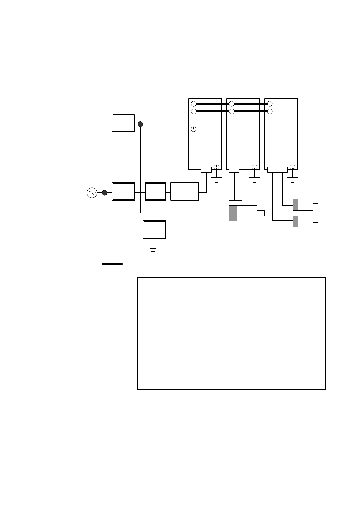
φ
Basic configuration using αi PS (example)
Common Power
Supply
i PS
α
Spindle Amplifier
i SP
α
Servo Amplifier
i SV
α
DC link
(300VDC)
200 to 240 VAC
3φ
Circuit
breaker 2
Circuit
breaker 1
Units prepared by the machine tool builder
Magnetic
contactor
Lightning
surge
protector
NOTE
1 For how to use the αi PS together with the αi SV
and α
MODULE".
2 A magnetic contactor, AC line filter, and circuit
breakers are always required.
3 To protect the unit from surge currents caused by
lightning, connect surge absorbers between lines,
and between the lines and ground, at the power
inlet of the power magnetic cabinet. See
APPENDIX A for details.
4 When using the 3φ fan motor, breaker 2 can be
shared.
200R,200S
1φ
AC reactor
(note 4)
3φ
fan motor
3
Spindle motor
Servo motor
i SP, see Chapter 4, "HOW TO SELECT THE
- 4 -
Page 29
B-65282EN/06 1.CONFIGURATION
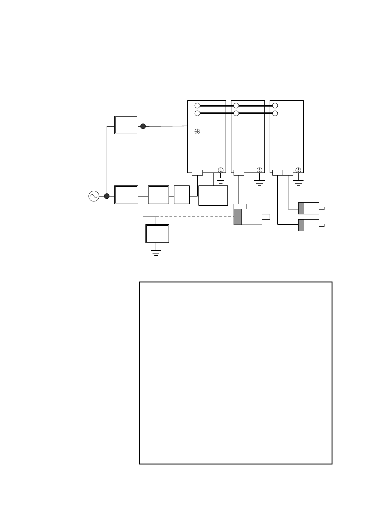
φ
Basic configuration using αi PSR (example)
Common Power
supply
i PS
α
R
Spindle amplifier
i SP
α
Servo amplifier
i SV
α
DC link
(300VDC)
200 to 240 VAC
3φ
Circuit
breaker 2
Circuit
breaker 1
Units prepared by the machine tool builder
Magnetic
contactor
Lightning
surge
protector
(note 5)
NOTE
1 For how to use the αi PSR together with the αi SV
and α
MODULE".
2 A magnetic contactor, AC line filter, and circuit
breakers are always required.
3 To protect the unit from surge currents caused by
lightning, connect surge absorbers between lines,
and between the lines and ground, at the power
inlet of the power magnetic cabinet. See
APPENDIX A for details.
4 When an insulating transformer is installed,
high-frequency noise to the Power Supply is
reduced, so the AC line filter is not required. If the
insulating transformer is installed outside the power
magnetic cabinet, and the cable connecting the
amplifier is exposed, the cable must be covered
with a grounded metal duct, or an AC line filter
must be installed.
5 When using the 3φ fan motor, breaker 2 can be
shared.
200R,200S
1φ
AC
line
filter
Regenerative
3
φ
discharge
unit
fan motor
3
Spindle motor
Servo motor
i SP, see Chapter 4, "HOW TO SELECT THE
- 5 -
Page 30

1.CONFIGURATION B-65282EN/06
1.2.2 400-V Input Series
(1) αi PS series (Power Supply).............................................(Basic)
(2) αi SV series (Servo Amplifier).........................................(Basic)
(3) αi SP series (Spindle Amplifier).......................................(Basic)
(4) AC reactor.........................................................................(Basic)
(5) Connectors (for connection cables)..................................(Basic)
(6) Fuses ..............................................................................(Basic)
(7) DBM (Dynamic brake module)........................................(Basic)
- 6 -
Page 31

B-65282EN/06 1.CONFIGURATION
φ
Basic configuration using αi PS (example)
Common Power
Supply
i PS
α
Spindle Amplifier
i SP
α
Servo Amplifier
i SV
α
DC link
(300VDC)
200 to 240 VAC
3φ
400 to 480 VAC
3φ
Circuit
breaker 2
Lightning
surge
protector
Circuit
breaker 1
Circuit
breaker 3
Units prepared by the machine tool builder
Magnetic
contactor
Lightning
surge
protector
NOTE
1 For the control Power Supply, single–phase
200VAC is required.
2 For how to use the αi PS together with the αi SV
and α
MODULE".
3 A magnetic contactor, AC line filter, and circuit
breakers are always required.
4 To protect the unit from surge currents caused by
lightning, connect surge absorbers between lines,
and between the lines and ground, at the power
inlet of the power magnetic cabinet. See
APPENDIX A for details.
5 Measures must be taken to detect the operation
(trip) of circuit breaker 3.
6 When using the 3φ fan motor, breaker 2 can be
shared.
200R,200S
1
φ
AC reactor
Lightning
surge
protector
(note 6)
3φ
fan motor
3
Spindle motor
Servo motor
i SP, see Chapter 4, "HOW TO SELECT THE
- 7 -
Page 32

1.CONFIGURATION B-65282EN/06
1.3 SERVO AMPLIFIERS
αi PS series (Power Supply)
The αi PS series power supplies are used as a main power supply of
motor power and as a common power supply to supply control power
to servo amplifiers. Select an appropriate Power Supply according to
the output levels of the servo motor and spindle motor used.
There are three types of α
<1> 200-V input series
This Power Supply is designed to provide a main power
supply of 200 to 240 V. The module uses power regeneration
that returns energy to the power supply during motor
deceleration (regeneration).
<2> 400-V input series
This Power Supply can be connected to a main power supply
of 400 to 480V without a transformer. The module uses power
regeneration that returns energy to the power supply during
motor deceleration (regeneration). It is used together with a αi
SV series and αi SP series of the 400-V input series.
<3> αi PS
series
R
This Power Supply is designed to provide a main power
supply of 200 to 240 V. The module uses resistance
regeneration that allows energy to be consumed by resistance
during motor deceleration (regeneration).
<4> Regenerative discharge unit
This unit is a resistance used to consume energy during motor
deceleration (regeneration). This unit is required whenever the
is used.
αi PS
R
αi PS - x HV
(A) (B) (C)
(A) Model name: PS = Power Supply
PS
(B) Rated output: Numeric value representing a continuous rating in kW
(C) For a 400-V input series, "HV" is added.
i PS series, as follows:
= Power Supply (resister discharge type)
R
- 8 -
Page 33

B-65282EN/06 1.CONFIGURATION
αi SV series (Servo Amplifier)
The αi SV series amplifiers are used to drive a servo motor. Select an
appropriate amplifier according to the servo motor connected.
There are two types of α
i SV series, as follows:
<1> 200-V input series
This Amplifier drives a servo motor of the 200-V input series.
Amplifiers for one axis, two axes, and three axes are available.
<2> 400-V input series
This Amplifier drives a servo motor of the 400-V input series.
Amplifiers for one axis and two axes are available.
αi SV x / x / x HV L
(A) (B) (C) (D) (E)(F)
(A) Model name: SV = Servo amplifier
(B) L-axis maximum output current value [Apeak]
(C) M-axis maximum output current value [Apeak]
(D) N-axis maximum output current value [Apeak]
(E) For an amplifier supporting 400-V input, "HV" is added.
(F) For an amplifier supporting HRV4 control, "L" is added.
αi SP series (Spindle Amplifier)
The αi SV series amplifiers are used to drive a spindle motor. Select
an appropriate amplifier according to the spindle motor connected.
There are two types of α
<1> 200-V input series
This Amplifier drives a spindle motor of the 200-V input
series.
<2> 400-V input series
This Amplifier drives a spindle motor of the 400V input
series.
αi SP x HV
(A) (B) (C)
(A) Model name: SP = Spindle amplifier module
(B) Output: Numeric value representing the 30-minutes rating of
a matching standard motor (αi) in kW
(C) For an amplifier supporting 400-V input, "HV" is added.
i SP series, as follows:
- 9 -
Page 34

1.CONFIGURATION B-65282EN/06
1.4 LINEUP
Input
Size
60mm-wide
Without external
fin
60mm-wide
With external fin
90mm-wide
With external fin
With external fin
With external fin
power
supply
200V 3 4, 20 4/4, 4/20
400V 10HV 10/10HV
200V 5.5 5.5 2.2, 5.5 40, 80
400V 5.5HV 20HV
200V 11, 15 11, 15 160L
400V 11HV, 18HV 11HV, 15HV 80HVL
200V 26, 30, 37 22, 26, 30, 37 360 150mm-wide
400V 30HV, 45HV 30HV, 45HV 180HV
200V 55 45, 55 300mm-wide
400V 75HV, 100HV 75HV, 100HV 360HV
αi PS αi PS
R
αi SP αi SV
20/20
20/40, 40/40
160, 20L
40L, 80L
40HV
80HV
10HVL
20HVL
40HVL
40/80, 80/80
20/20L
20/40L
40/40L
20/20HV
10/10HVL
80/160
160/160
40/80L
80/80L
20/40HV
40/40HV
40/80HV
80/80HV
20/20HVL
20/40HVL
40/40HVL
4/4/4
20/20/20
20/20/40
- 10 -
Page 35

B-65282EN/06 2.SPECIFICATIONS
2 SPECIFICATIONS
Chapter 2, "SPECIFICATIONS", consists of the following sections:
2.1 INPUT POWER..........................................................................12
2.2 ENVIRONMENTAL CONDITIONS.........................................25
2.3 SPECIFICATIONS OF THE MODULES..................................33
2.4 WEIGHT.....................................................................................43
- 11 -
Page 36

2.SPECIFICATIONS B-65282EN/06
A
r
A
−
2.1 INPUT POWER
Power supply of 200-V input series
(1) Power specification
Item Specification
Main power supply
voltage
Power supply voltage for
the control
Allowable voltage
deviation
Instantaneous power
failure guarantee time
Power frequency 50/60Hz, ±1Hz
Power supply unbalance ±5% of the rated voltage or less
Power supply impedance
(Note)
NOTE
When the power supply impedance is high, and the
voltage variation exceeds the specified values, an
alarm (DC link undervoltage alarm or DC link
overvoltage alarm) can be issued in αi PS, or the
output of the motor can decrease.
[Method of checking power supply impedance]
C power
supply
Three-phase 200 VAC to 240 VAC
Single-phase 200 VAC to 240 VAC (input from
connector CX1A)
-15% to +10% (including voltage variation due
to load)
3ms
The voltage variation must be within ±7% when
a maximum output is produced for voltage at
non-load time (power running and regeneration).
R
L+
S
L-
T
G
L+
L- U V
Motor
W
G
i
C voltmete
E
i
α
PS
10
EE
(%)7(%)100
<×
0
α
SV
i
α
SP
E0 : Voltage at non-load time
E1 : Voltage at maximum output time (power running and
regeneration)
(2) The power supply for αi PS control (power supply input of
CX1A) must be turned on before or at the same time when the
CNC is turned on. For the timing of power-on at the same time
when the CNC is turned on, refer to the chapter of the power
supply in the hardware connection manual of the CNC used.
- 12 -
Page 37

B-65282EN/06 2.SPECIFICATIONS
(3) It is recommended that a capacitor unit for power-factor
improvement not be installed. This is because the capacitor unit
for power-factor improvement may adversely affect power
regeneration.
(4) The rated output of the motor is guaranteed for the rated input
voltage. If the input voltage changes, the rated output may not
appear even when the input voltage change is within the
allowable range.
(5) When the power supply is used in an area where the input
voltage is not within the range of 200 to 240 VAC, a power
transformer is required. When a power transformer is to be
provided by the user, the power must satisfy the specifications
listed below.
αiPS
α
Rated capacity (kVA)
Secondary current (A)
Secondary output
voltage
Secondary voltage
regulation
Secondary voltage
deviation
iPS
5.5
9 17 22 37 44 53 64 79
26 49 63 106 127 153 185 228
αiPS
11
Rated capacity
Secondary current
Secondary output
voltage
Secondary voltage
regulation
Secondary voltage
deviation
iPS
α
(kVA)
(A)
αiPS
15
R
αiPS
26
iPS
α
(2kW output)
3.5 5 9 12
10 14.5 26 35
αiPS
200 to 240V
3
R
αiPS
30
5%
±3%
(3kW output)
37
αiPSR 3
200 to 240V
αiPS 55
(45kW output)
αiPSR 5.5
(5.5kW output)
5%
±3%
αiPS 55
(55kW output)
αiPSR 5.5
(7.5kW output)
* The secondary current indicates the current value observed when
the secondary output voltage is 200 V.
(6) Ground
The main circuit and 200V control power supply must be
grounded through the neutral point or one phase of the
three-phase power supply.
(7) Noise filter
To satisfy the EMC regulation enforced in the EU countries, a
noise filter must be installed in the power supply input section.
- 13 -
Page 38

2.SPECIFICATIONS B-65282EN/06
A
r
A
−
Power supply of 400-V input series
(1) Power specification
Item Specification
Three-phase 400 VAC to 480 VAC
Star connection, neutral grounding (For
details, see Items (5) and (6).)
Main power supply
voltage
Power supply voltage for
the control
Allowable voltage
deviation
Instantaneous power
failure guarantee time
Power frequency 50/60Hz, ±1Hz
Power supply unbalance ±5% of the rated voltage or less
Power supply impedance
(Note)
N
Single-phase 200 VAC to 240 VAC (input
from connector CX1A)
(For details, see Item (7).)
-15% to +10% (including voltage variation
due to load)
3ms
The voltage variation must be within ±7%
when a maximum output is produced for
voltage at non-load time (power running
and regeneration).
NOTE
When the power supply impedance is high, and the
voltage variation exceeds the specified values,
alarm (DC link undervoltage alarm or DC link
overvoltage alarm) can be issued in αi PS, or the
output of the motor can decrease.
[Method of checking power supply impedance]
C power
supply
R
L+
S
L-
T
G
R
S
T
G
L+
L- U V
Motor
W
G
i
C voltmete
E
i
α
PS
10
EE
(%)7(%)100
<×
0
α
SV
i
α
SP
E0 : Voltage at non-load time
E1 : Voltage at maximum output time (power running and
regeneration)
- 14 -
Page 39

B-65282EN/06 2.SPECIFICATIONS
(2) The power supply for αi PS control (power supply input of
CX1A) must be turned on before or at the same time when the
CNC is turned on. For the timing of power-on at the same time
when the CNC is turned on, refer to the chapter of the power
supply in the hardware connection manual of the CNC used.
(3) It is recommended that a capacitor unit for power-factor
improvement not be installed. This is because the capacitor unit
for power-factor improvement may adversely affect power
regeneration.
(4) The rated output of the motor is guaranteed for the rated input
voltage. If the input voltage changes, the rated output may not
appear even when the input voltage change is within the
allowable range.
(5) Power supply voltage for the main circuit
• The power specification of the main circuit for the 400-V
input series of the αi series servo amplifier is as follows:
<1> Star connection
<2> Neutral grounding on the power supply side
<3> A PE is provided on the power line. (The PE of the
amplifier and motor is connected to the PE of the
power line.)
<4> The inter-phase voltage of the power supply is 400
VAC to 480 VAC (-15%, +10%).
• If the power supply does not satisfy the conditions above,
the power supply needs to be converted to a power supply
for neutral grounding by using a star connection and an
isolating-transformer.
• The 400-V input series of the αi series servo amplifier is
designed in compliance with the safety standard EN50178
to implement insulation design of the pattern and
components of the printed circuit board by ensuring that the
phase voltage of the power supply and the voltage between
grounds connected to the neutral point of the star
connection are AC 300 Vrms or below.
Accordingly, if the power supply does not satisfy the
conditions above, the pattern and components of the printed
circuit board are poorly insulated. This can cause very
dangerous states including a failure in servo amplifier
operation and the occurrence of a high voltage at exposed
areas.
- 15 -
Page 40

2.SPECIFICATIONS B-65282EN/06
(6) Example of connecting the Power supply of the main circuit
No. Power system Power specification Power supply of amplifier
1 TN-power system • Star connection
• Neutral grounding on the power
supply side
• PE provided on the power line
• Power supply voltage specification
400 VAC to 480 VAC (-15%,+10%)
2 TN-power system • Star connection
• Neutral grounding on the power
supply side
• PE provided on the power line
• Power supply voltage specification
Not within the range 400 VAC to
480 VAC (-15%, +10%)
3 TN-power system • Delta connection
• Single-phase grounding on the
power supply side
• PE provided on the power line
4 TT-power system • Star connection
• Neutral grounding on the power
supply side
• No PE provided on the power line
5 TT-power system • Delta connection
• Single-phase grounding on the
power supply side
• No PE provided on the power line
6 IT-power system • Star connection
• No direct ground connection made
on the power supply side
• No PE provided on the power line
7 IT-power system • Delta connection
• No direct ground connection made
on the power supply side
• No PE provided on the power line
* The TN-power system, TT-power system, and IT-power system
are based on the DC power distribution system standard
IEC60364.
• Directly connectable to the power supply
(No transformer is required.)
[When the power supply voltage is lower than
the specified power supply voltage]
The power supply voltage is increased with
an auto-transformer.
[When the power supply voltage is higher
than the specified power supply voltage]
The power supply voltage is decreased
with an auto-transformer.
Before starting to use the power supply,
check that it conforms to the relevant
safety standards.
• An isolating-transformer is used.
• A star connection is made on the
secondary side of an isolating-transformer,
and the neutral point is grounded.
• An isolating-transformer is used.
• A star connection is made on the
secondary side of an isolating-transformer,
and the neutral point is grounded.
- 16 -
Page 41
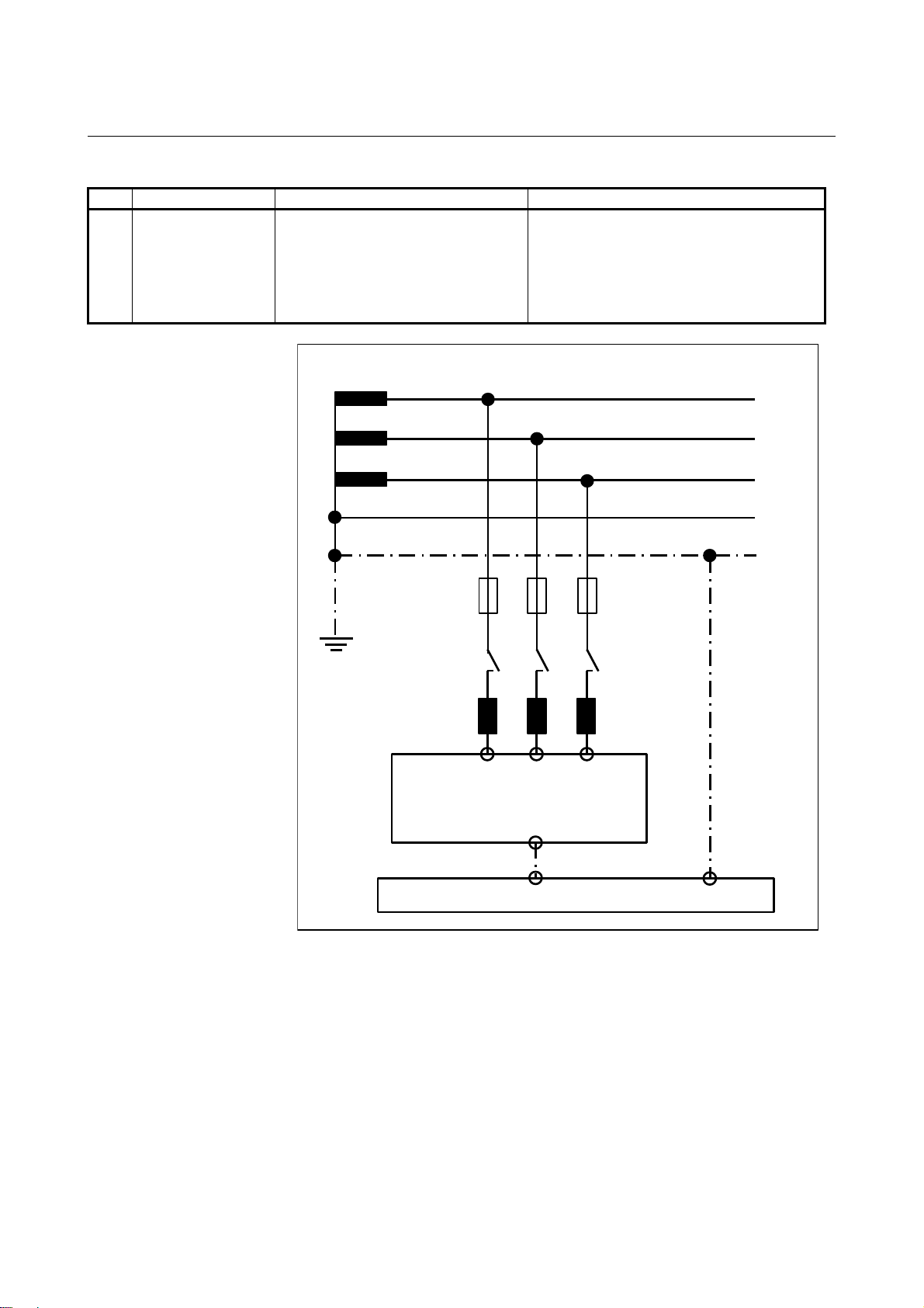
B-65282EN/06 2.SPECIFICATIONS
)
A
(a) TN-power system
No. Power system Power specification Power supply of amplifier
1 TN-power system • Star connection
• Neutral grounding on the power
supply side
• PE provided on the power line
• Power supply voltage specification
400 VAC to 480 VAC (-15%,+10%)
• Directly connectable to the power supply
(No transformer is required.)
Power source
L1
L2
L3
N
PE
Breaker
or
Fuse
Contactor
C Reactor
PS
α
i
L1 L2 L3
PE (FLANGE
Earth Plate of Cabinet
- 17 -
Page 42

2.SPECIFICATIONS B-65282EN/06
A
)
(b) TN-power system
No. Power system Power specification Power supply of amplifier
2 TN-power system • Star connection
• Neutral grounding on the power
supply side
• PE provided on the power line
• Power supply voltage specification
Not within the range 400 VAC to
480 VAC (-15%, +10%)
Power source
[When the power supply voltage is lower than
the specified power supply voltage]
The power supply voltage is increased with
an auto-transformer.
[When the power supply voltage is higher
than the specified power supply voltage]
The power supply voltage is decreased
with an auto-transformer.
Before starting to use the power supply,
check that it conforms to the relevant
safety standards.
L1
L2
L3
Breaker
Auto-
transformer
Breaker
or
Fuse
Contactor
C Reactor
αi PS
N
PE
or
Fuse
PE
N
L1 L2 L3
PE (FLANGE
Earth Plate of Cabinet
- 18 -
Page 43

B-65282EN/06 2.SPECIFICATIONS
A
r
)
(c) TN-power system
No. Power system Power specification Power supply of amplifier
3 TN-power system • Delta connection
• Single-phase grounding on the
Power supply side
• PE provided on the power line
• An isolating-transformer is used.
• A star connection is made on the
secondary side of an isolating-transformer,
and the neutral point is grounded.
Power source
L1
L2
L3
N
PE
Breaker
or
Fuse
Isolating -
transformer
Breaker
Contactor
C Reacto
αi PS
PE
N
or
Fuse
L1 L2 L3
PE (FLANGE
Earth Plate of Cabinet
- 19 -
Page 44

2.SPECIFICATIONS B-65282EN/06
A
)
(d) TT-power system
No. Power system Power specification Power supply of amplifier
4 TT-power system • Star connection
• Neutral grounding on the power
supply side
• No PE provided on the power line
Power source
Breaker
or
Fuse
• An isolating-transformer is used.
• A star connection is made on the
secondary side of an isolating-transformer,
and the neutral point is grounded.
L1
L2
L3
Isolating-
transformer
Breaker
Contactor
C Reactor
α
i
or
Fuse
PS
PE
N
PE
L1 L2 L3
PE (FLANGE
Earth Plate of Cabinet
- 20 -
Page 45

B-65282EN/06 2.SPECIFICATIONS
A
r
)
(e) TT-power system
No. Power system Power specification Power supply of amplifier
5 TT-power system • Delta connection
• Single-phase grounding on the
power supply side
• No PE provided on the power line
• An isolating-transformer is used.
• A star connection is made on the secondary
side of an isolating-transformer, and the
neutral point is grounded.
Power source
L1
L2
L3
Breaker
or
Fuse
Isolating -
transformer
Breaker
Contactor
C Reacto
αi PS
PE
N
PE
or
Fuse
L1 L2 L3
PE (FLANGE
Earth Plate of Cabinet
- 21 -
Page 46

2.SPECIFICATIONS B-65282EN/06
A
r
r
)
(f) IT-power system
No. Power system Power specification Power supply of amplifier
6 IT-power system • Star connection
• No direct ground connection
made on the power supply side
• No PE provided on the power line
Power source
Breaker
or
Fuse
• An isolating-transformer is used.
• A star connection is made on the secondary
side of an isolating-transformer, and the
neutral point is grounded.
L1
L2
L3
Isolating -
transformer
Breaker
Contacto
C Reacto
αi PS
PE
N
PE
or
Fuse
L1 L2 L3
PE (FLANGE
Earth Plate of Cabinet
- 22 -
Page 47

B-65282EN/06 2.SPECIFICATIONS
A
r
)
(g) IT-power system
No. Power system Power specification Power supply of amplifier
7 IT-power system • Delta connection
• No direct ground connection
made on the power supply side
• No PE provided on the power line
• An isolating-transformer is used.
• A star connection is made on the secondary
side of an isolating-transformer, and the
neutral point is grounded.
Power source
L1
L2
L3
Breaker
or
Fuse
Isolating -
transformer
Breaker
Contactor
C Reacto
αi PS
PE
N
PE
or
Fuse
L1 L2 L3
PE (FLANGE
Earth Plate of Cabinet
- 23 -
Page 48

2.SPECIFICATIONS B-65282EN/06
(7) Control power supply connection
• Specification of the control power supply voltage for the
400V input series of the αi series servo amplifier
Single-phase 200 VAC to 240 VAC (-15%, +10%)
• When the power supply has a neutral point, power can be
supplied from the neutral point and phase voltage to the
control power supply.
When an isolating-transformer is used, connect one phase of
the control power supply to the neutral point on the
secondary side of the isolating-transformer.
(a) Example of connection when the three-phase power supply
voltage of the main circuit is 400 VAC to 415 VAC (-15%,
+10%)
With the following connection, the control power supply
voltage can be converted to single-phase 200 VAC to 240
VAC (-15%, +10%):
Power source
L1
L2
L3
N
PE
Breaker
5A
PS
α
i
200R 200S PE
CX1A
(b) Example of connection when the three-phase power supply
voltage of the main circuit is 460 VAC or more
By using an auto-transformer, ensure that the single-phase
power supply voltage for the control power supply is 200
VAC to 240 VAC (-15%, +10%).
(NOTE) Before starting to use the auto-transformer, check
that it conforms to the relevant safety standards.
Power source
L1
L2
L3
N
Auto-
transformer
PE
- 24 -
αi PS
Breaker
5A
200R 200S
CX1A
PE
Page 49

B-65282EN/06 2.SPECIFICATIONS
2.2 ENVIRONMENTAL CONDITIONS
The servo amplifier αi series must be installed in a sealed type cabinet
to satisfy the following environmental requirements. For how to
design such a cabinet, see Appendix G, "EXAMPLES OF
RECOMMENDED POWER MAGNETICS CABINETS FOR
SERVO AMPLIFIER INSTALLATION".
(1) Ambient Temperature
Ambient temperature of the unit :
0 to 55°C (at operation)
-20 to 60°C (at keeping and transportation)
(2) Humidity
Normally 90% RH or below, and condensation-free
(3) Vibration
In operation : Below 0.5G
(4) Atmosphere
Prevent conductive, flammable, or corrosive foreign matters,
mists, or water droplets from entering the unit
WARNING
If conductive or flammable foreign matters enter the
unit, explosion or corruption may be caused.
If corrosive or conductive mists or water droplets are
attached to an electronic circuit, unexpected
operation may be caused in the circuit.
The electronic circuit portion must be installed in an
environment of pollution level 2 specified by
IEC60664-1. To achieve pollution level 2 in a
severe machine tool environment, it is generally
necessary to install the portion in a cabinet that
satisfies IP54.
(5) Notes on Installation
The αi series servo amplifier is designed to be installed in the
power magnetics cabinet, with its heat sink projecting through
the back of the cabinet. This carries away the heat generated by
the semiconductors, thus preventing heat from building up in the
cabinet as much as possible. Therefore, note the following when
installing the amplifier.
(a) Take appropriate measures to prevent coolant, oil mist, or
chips from being adhered to the radiator and fan motors. A
deposit of coolant, oil mist, or chips on the radiator or fan
motors can lower the cooling efficiency. In some cases, the
amplifier characteristics cannot sometimes be satisfied. The
deposit may also reduce the service life of the fan motors or
semiconductors.
- 25 -
Page 50

2.SPECIFICATIONS B-65282EN/06
When outside air is drawn in to the radiator, mount an air
filter on the air inlet. In addition, ensure to seal doors and
parts where cables are drawn in and out.
(b) No dust or cutting fluid must be able to enter through the
exhaust port. The flow of cooling air must not be
obstructed.
(c) The amplifier must be installed where it can be easily
inspected, removed, and remounted for maintenance.
(d) Current lines and signal lines must be separated and noise
must be suppressed. See the section 5.3 and the connection
manual for each CNC for details.
(e) Each amplifier must be installed vertically.
(f) Servo amplifiers are to be arranged horizontally. When
arranging servo amplifiers vertically from necessity, note
the following:
1) Ensure that cooling air from a lower amplifier does not
blow directly against the upper amplifier. Otherwise,
radiation performance can degrade and the rated output
may not be satisfied.
2) Ensure that the flow of cooling air of a lower amplifier
is not impeded.
(g) Maintenance areas must be reserved for each servo
amplifier.
- 26 -
Page 51

B-65282EN/06 2.SPECIFICATIONS
0
A
0
A
(6) Derating
Consider derating as shown below, according to ambient
temperatures.
(a) αi SV series
The solid line indicates derating when HRV2 is applied, the
dotted line indicates derating when HRV3 is applied, and
the dot-dash line indicates derating when HRV4 is applied.
αi SV 40 to 160
100%
80%
60%
40%
20%
Percentage of
0%
Rated Output Current
10 20 30 40 50 60 °C
mbient temperature
αi SV 20/40 to 160/160
100%
80%
60%
40%
Percentage of
Rated Output Current
20%
0%
10 20 30 40 50 60 °C
mbient temperature
CAUTION
HRV4 cannot be applied to A06B-6114-Hxxx and
-6124-Hxxx.
- 27 -
Page 52

2.SPECIFICATIONS B-65282EN/06
0
A
0
αi SV 4 to 20
αi SV 4/4 to αi SVM20/20
αi SV 4/4/4 to αi SV 20/20/40
100%
80%
60%
40%
Percentage of
Rated Output Current
20%
0%
10 20 30 40 50 60 °C
mbient temperature
αi SV 360
100%
80%
60%
40%
Percentage of
Rated Output Current
20%
0%
10 20 30 40 50 60 °C
Ambient temperature
αi SV 20L to 160L (When HRV4 is applied)
100%
Percantage of
Percantage of
Rated Output Current
Rated Output Current
100%
80%
80%
60%
60%
40%
40%
20%
20%
0%
0%
0 10 20 30 40 50
0 10 20 30 40 50
Ambient temperature
Ambient temperature
60 °C
60 °C
CAUTION
HRV4 cannot be applied to A06B-6114-Hxxx and
-6124-Hxxx.
- 28 -
Page 53

B-65282EN/06 2.SPECIFICATIONS
0
αi SV 20/20L to 80/80L (When HRV4 is applied)
100%
100%
80%
80%
60%
60%
40%
Percantage of
Percantage of
Rated Output Current
Rated Output Current
40%
20%
20%
0%
0%
0 10 20 30 40 50
0 10 20 30 40 50
Ambient temperature
Ambient temperature
60 °C
60 °C
αi SV 10HV to 80HV
100%
80%
60%
40%
Percentage of
Rated Output Current
20%
0%
10 20 30 40 50 60 °C
Ambient temperature
αi SV 180HV
100%
Percantage of
Percantage of
Ra ted Outpu t Curren t
Ra ted Outpu t Curren t
100%
80%
80%
60%
60%
40%
40%
20%
20%
0%
0%
0 10 20 30 40 50
0 10 20 30 40 50
Ambient temperature
Ambient temperature
60 °C
60 °C
CAUTION
HRV4 cannot be applied to A06B-6114-Hxxx and
-6124-Hxxx.
- 29 -
Page 54

2.SPECIFICATIONS B-65282EN/06
0
0
αi SV 360HV
αi SV 10/10HV to 20/20HV
αi SV 20/40HV to 80/80HV
100%
100%
80%
80%
60%
60%
40%
40%
Percantage of
Percantage of
20%
20%
Rated Output Curren t
Rated Output Curren t
0%
0%
0 10 20 30 40 50
0 10 20 30 40 50
Ambient temperature
Ambient temperature
100%
80%
60%
40%
Percentage of
Rated Output Current
20%
0%
100%
80%
60%
40%
Percentage of
Rated Output Current
20%
0%
60 °C
60 °C
10 20 30 40 50 60 °C
Ambient temperature
10 20 30 40 50 60 °C
Ambient temperature
- 30 -
Page 55

B-65282EN/06 2.SPECIFICATIONS
0
A
αi SV 10HVL to 80HVL (When HRV4 is applied)
100%
80%
Percentage of
60%
40%
20%
0%
10 20 30 40 50 60 °C
mbient temperature
αi SV 10/10HVL to 40/40HVL (When HRV4 is applied)
100%
100%
80%
80%
60%
60%
40%
40%
Percantage of
Percantage of
20%
Rated Output Current
Rated Output Current
20%
0%
0%
0 10 20 30 40 50
0 10 20 30 40 50
60 °C
60 °C
Ambient temperature
Ambient temperature
CAUTION
HRV4 cannot be applied to A06B-6114-Hxxx and
-6124-Hxxx.
- 31 -
Page 56

2.SPECIFICATIONS B-65282EN/06
0
A
(b) αi SP series
αi SP 2.2 to 55
αi SP 5.5HV to 100HV
30
min.
20
min.
10
min.
Available Operating Time
0
10 20 30 40 50 60 °C
mbient temperature
- 32 -
Page 57

B-65282EN/06 2.SPECIFICATIONS
2.3 SPECIFICATIONS OF THE MODULES
2.3.1 αi PS series
200-V input series - power source regeneration type
Model
Item
Power supply (Note 1)
capacity
Rated output capacity (Note 2) 6.8kW 13.2kW 17.5kW 29.8kW 35kW 43kW 65kW
Control method Regenerative control (power source generation)
Main circuit 200 to 240VAC +10%,-15%,3φ 50/60Hz, ±1Hz
Control power 200 to 240VAC +10%,-15%,1φ 50/60Hz, ±1Hz
Main circuit 9kVA 17kVA 22kVA 37kVA 44kVA 53kVA 79kVAPower equipment
Control power 0.7kVA
Output capacities for motor selection
Model
Item
Rated output capacity 5.5kW 11kW 15kW 26kW 30kW 37kW 55kW
Maximum output capacity 13kW 24kW 34kW 48kW 64kW 84kW 125kW
Peak maximum output capability 22kW 38kW 51kW 73kW 85kW 106kW 192kW
Output capacities for motor selection (when A06B-6110-Hxxx is
used)
Model
Item
Maximum output capacity 11kW 20kW 28kW 40kW 53kW 70kW 104kW
Peak maximum output capability 20kW 34kW 46kW 66kW 77kW 96kW 174kW
αi PS 5.5 αi PS 11 αi PS 15 αi PS 26 αi PS 30 αi PS 37 αi PS 55
αi PS 5.5 αi PS 11 αi PS 15 αi PS 26 αi PS 30 αi PS 37 αi PS 55
NOTE
1 A power transformer is necessary for voltages
other than those listed in above table.
2 When selecting an αi PS unit, use "Output
capacities for motor selection".
3 The values in the above table are applied when
A06B-6140-Hxxxx is used. When
A06B-6110-Hxxxx is used, the values of the
maximum output capacity and peak maximum
output capacity differ as shown in the table below.
αi PS 5.5 αi PS 11 αi PS 15 αi PS 26 αi PS 30 αi PS 37 αi PS 55
- 33 -
Page 58

2.SPECIFICATIONS B-65282EN/06
200-V input series - resister discharge type (αi PSR)
Model
Item
Power supply (Note 1)
capacity
Rated output capacity (Note 2) 3.8kW 9.4kW
Control method Regenerative control (resister discharge)
Main circuit 200 to 240VAC +10%,-15%,3φ 50/60Hz, ±1Hz
Control power 200 to 240VAC +10%,-15%,1φ 50/60Hz, ±1Hz
Main circuit 5kVA 12kVA Power equipment
Control power 0.5kVA
Output capacities for motor selection
Model
Item
Rated output capacity 3kW 7.5kW
Maximum output capacity 12kW 20kW
NOTE
1 A power transformer is necessary for voltages
other than those listed in above table.
2 When selecting an αi PSR unit, use "Output
capacities for motor selection".
3 The αi PSR 3 and αi PSR 5.5 require regenerative
discharge unit.
αi PSR 3 αi PSR 5.5
αi PSR 3 αi PSR 5.5
- 34 -
Page 59

B-65282EN/06 2.SPECIFICATIONS
400-V input series - power source regeneration type
Model
Item
Power supply (Note 1)
capacity
Rated output capacity (Note 2) 13kW 21kW 35kW 50kW 82kW 110kW
Control method Regenerative control (power source regeneration)
Main circuit 400 to 480VAC +10%,-15%,3φ 50/60Hz, ±1Hz
Control power 200 to 240VAC +10%,-15%,1φ 50/60Hz, ±1Hz
Main circuit 17kVA 26kVA 44kVA 64kVA 107kVA 143kVAPower equipment
Control power 0.7kVA
Output capacities for motor selection
Model
Item
Rated output capacity 11kW 18kW 30kW 45kW 75kW 100kW
Maximum output capacity 24kW 42kW 72kW 102kW 144kW 180kW
Peak maximum output capability 38kW 64kW 96kW 137kW 193kW 220kW
NOTE
1 A power transformer is necessary for voltages
other than those listed in above table.
2 When selecting an αi PS unit, use "Output
capacities for motor selection".
3 The values in the above table are applied when
A06B-6150-Hxxxx is used. When
A06B-6120-Hxxxx is used, the values of the
maximum output capacity and peak maximum
output capacity differ as shown in the table below.
Output capacities for motor selection (when A06B-6120-Hxxx is
used)
Model
Item
Maximum output capacity 20kW 35kW 60kW 85kW 120kW 150kW
Peak maximum output capability 34kW 58kW 87kW 124kW 175kW 200kW
αi PS
11HV
αi PS
11HV
αi PS
11HV
αi PS
18HV
αi PS
18HV
αi PS
18HV
αi PS
30HV
αi PS
30HV
αi PS
30HV
αi PS
45HV
αi PS
45HV
αi PS
45HV
αi PS
75HV
αi PS
75HV
αi PS
75HV
αi PS
100HV
αi PS
100HV
αi PS
100HV
- 35 -
Page 60

2.SPECIFICATIONS B-65282EN/06
How to calculate the power equipment capacity
Calculate the power equipment capacity using the formula below.
(kVA)capacity supply Power
=
×
(kW) 4.3Section in calculatedcapacity Rated
(kW) modulesupply power ofcapacity Rated
(kVA)output rated having modulesupply power ofcapacity supply Power
NOTE
Select a Power supply for which, when the motor is
accelerated, the input voltage variation does not
exceed 7%.
How to calculate the input current of the αi PS
Calculate the input current of the αi PS by using the formula below.
Refer to the result when selecting the MCC, power cable, and circuit
breaker 1, to be connected to the αi PS input section.
(Margin for selection: 1 to 1.5 times)
(Arms)current input PS ×
=
×
(kVA)capacity equipment Power
(Vrms) tagesupply vol Nominal3
(margin) 1.2
NOTE
Under normal conditions, assume that the nominal
supply voltage (Vrms) is 200 Vrms for the 200-V
input series or 400 Vrms for the 400-V input series.
- 36 -
Page 61

B-65282EN/06 2.SPECIFICATIONS
2.3.2 αi SV series
Specifications (common)
Item Specifications
Main circuit control
method
Applicable CNC
CAUTION
HRV4 cannot be applied to A06B-6114-Hxxx and
-6124-Hxxx.
200-V input series - 1-axis amplifier
Name Axis
αi SV 4
αi SV 20
αi SV 20L
αi SV 40
αi SV 40L
αi SV 80
αi SV 80L
αi SV 160
αi SV 160L
αi SV 360
Sine-wave PWM control with transistor (IGBT) bridge
16i-B, 18i-B, 21i-B, 0i-B/C/D, and 30i/31i/32i
Rated output current
[Arms]
- 1.5 4
- 6.5 20
- 6.5 20
- 13 40
- 13 40
- 19 80
- 19 80
- 45 160
- 45 160
- 115 360
Nominal current limit
[Apeak]
200-V input series - 2-axis amplifier
Name Axis
αi SV 4/4
αi SV 4/20
αi SV 20/20
αi SV 20/40
αi SV 40/40
αi SV 40/80
αi SV 80/80
αi SV 80/160
αi SV 160/160
αi SV 20/20L
Rated output current
[Arms]
L 1.5 4
M 1.5 4
L 1.5 4
M 6.5 20
L 6.5 20
M 6.5 20
L 6.5 20
M 13 40
L 13 40
M 13 40
L 13 40
M 19 80
L 19 80
M 19 80
L 19 80
M 39 160
L 39 160
M 39 160
L 6.5 20
M 6.5 20
Nominal current limit
[Apeak]
- 37 -
Page 62

2.SPECIFICATIONS B-65282EN/06
Name Axis
αi SV 20/40L
αi SV 40/40L
αi SV 40/80L
αi SV 80/80L
αi SV 80/160L
NOTE
The current limit (peak value) is a standard value. It
varies by about ±10%, depending on the circuit
constants.
200-V input series - 3-axis amplifier
Name Axis
αi SV 4/4/4
αi SV 20/20/20
αi SV 20/20/40
400-V input series - 1-axis amplifier
Name Axis
αi SV 10HV
αi SV 20HV
αi SV 40HV
αi SV 80HV
αi SV 180HV
αi SV 360HV
αi SV 10HVL
αi SV 20HVL
αi SV 40HVL
αi SV 80HVL
Rated output current
[Arms]
L 6.5 20
M 13 40
L 13 40
M 13 40
L 13 40
M 19 80
L 19 80
M 19 80
L 19 80
M 39 160
Rated output current
[Arms]
L 1.5 4
M 1.5 4
N 1.5 4
L 6.5 20
M 6.5 20
N 6.5 20
L 6.5 20
M 6.5 20
N 13 40
Rated output current
[Arms]
- 3.1 10
- 5.6 20
- 9.1 40
- 18.2 80
- 58 180
- 115 360
- 3.1 10
- 5.6 20
- 9.1 40
- 18.2 80
Nominal current limit
[Apeak]
Nominal current limit
[Apeak]
Nominal current limit
[Apeak]
- 38 -
Page 63

B-65282EN/06 2.SPECIFICATIONS
400-V input series - 2-axis amplifier
Name Axis
αi SV 10/10HV
αi SV 20/20HV
αi SV 20/40HV
αi SV 40/40HV
αi SV 40/80HV
αi SV 80/80HV
αi SV 10/10HVL
αi SV 20/20HVL
αi SV 20/40HVL
αi SV 40/40HVL
Rated output current
[Arms]
L 3.1 10
M 3.1 10
L 5.6 20
M 5.6 20
L 5.6 20
M 9.1 40
L 9.1 40
M 9.1 40
L 9.1 40
M 18.2 80
L 18.2 80
M 18.2 80
L 3.1 10
M 3.1 10
L 5.6 20
M 5.6 20
L 5.6 20
M 9.1 40
L 9.1 40
M 9.1 40
NOTE
The current limit (peak value) is a standard value. It
varies by about ±10%, depending on the circuit
constants.
Nominal current limit
[Apeak]
- 39 -
Page 64

2.SPECIFICATIONS B-65282EN/06
2.3.3 αi SP series
200-V input series
αi SP
2.2
13A 27A 48A 63A 95A 111A 133A 165A 198A 250ARated output
αi I 0.5
αi I 1
Model
Item
(HRV type)
Main circuit control method Sine-wave PWM control with transistor (IGBT) bridge
Speed control range Speed ratio 1:100
Speed variation rate 0.1% or less of maximum speed (load variation: 10% to 100%)
Applicable CNC
Applicable motors
(typical examples)
(Note 1)
400-V input series
Model
Item
(HRV type)
Main circuit control method Sine-wave PWM control with transistor (IGBT) bridge
Speed control range Speed ratio 1:100
Speed variation rate 0.1% or less of maximum speed (load variation: 10% to 100%)
Applicable CNC
Applicable motors
(typical examples)
(Note 1)
αi SP
5.5
αi I 1.5
αi I 2
αi I 3
αi SP
Spindle HRV2 Spindle HRV1
αi I 6
αi I 8
αi I
αi SP
11
P
15
16i-B, 18i-B, 21i-B, 0i-B/C/D, and 30i/31i/32i
αi I 12
αi I
αi I
12
P
P
15
18
αi SP
22
αi I 15
αi I 18
αi I
P
αi I
P
22
30
αi SP
26
αi I
αi I
P
αi I
P
22
40
50
αi SP
30
αi I
P
60
αi SP
37
(Note 2)
(Note 3)
αi SP
5.5HV
14A 23A 32A 70A 107A 170A 200A Rated output
αi I 0.5HV
αi I 1HV
αi I 2HV
αI I 3HV
HRV2
αi SP
11HV
αi I 6HV
αi I 8HV
αi SP
15HV
16i-B, 18i-B, 21i-B, 0i-B/C/D, and 30i/31i/32i
αi I
15HV
P
αi SP
30HV
αi I 15HV
αi I 22HV
αi I
40HV
P
αi I
50HV
P
αi SP
45HV
HRV1
αi I 30HV
αi I 40HV
αi I
P
αi SP
75HV
注 3
αi I 60HV αi I 100HV
60HV
NOTE
1 For combinations of motor models and amplifier
models, refer to "Applicable spindle amplifier" in the
specification list in the descriptions manual of the
spindle motor.
2 Built-in spindle motors are applied.
3 For spindle HRV2, the rated current is derated as
follows:
αi SP37 85% αi SP45 79%, αi SP55 80%
αi SP15HV 94%, αi SP30HV 83%, αi SP45HV 72%
αi SP75HV 83%, αi SP100HV 91%
αi SP
45
αi I 30
αi I 40
αi SP
55
αi I 50
αi SP
100HV
- 40 -
Page 65

B-65282EN/06 2.SPECIFICATIONS
Types (A and B) of αi SP models and sensors applicable to each type
Either of two αi SP models, types A and B, is available for each
detector on the spindle to be used. The following lists combinations of
i SP type, applicable sensors, and functions.
an α
Configuration
αi SP
Spindle system configuration
Sensor on the motor
Sensor on the spindle
Rigid tapping O*1 O*2 O O O O*2 O O O
Orientation by a
position coder
Orientation by the
Function
external one-rotation
signal
synchronization
Threading O*6 O O O O O O
Cs-axis contour
control
(when a built-in motor is used)
(when a built-in motor is used)
Velocity synchronization O*2 O*6 O O O O*2 O O O *4 Spindle
TYPE A O O O O O O O
TYPE B O O O O O O O O O
αiM
αiMZ sensor
αiBZ sensor (*8)
α
iCZ I sensor
αi position coder
External 1-rotation O *3
αiBZ sensor
αiCZ IS sensor
α position coder S O *3
Phase synchronization
*1 The spindle and motor must be interconnected directly or with a
timing belt or gear. No orientation is available to adjust the
tapping start position.
*2 The spindle and motor must be interconnected with a timing belt
or gear.
*3 The spindle and detector must be interconnected in one-to-one
connection mode.
*4 Two motor amplifiers are required.
*5 Note that the stop position moves by a backlash between the
spindle and motor because of the theory of operation.
*6 The spindle and motor must be interconnected directly or with a
timing belt or gear in one-to-one connection mode.
*7 Before specifying spindle synchronization, perform orientation to
detect the one-rotation signal (PC1DT=1).
*8 The αiCZ analog output type is also applicable.
1 2 3 4 5 6 7 8 9
O O O O O O
O
O
O
O *3
O *3
O
O*6 O O O O O O
O*2 *5
O*6 O O O O*7 O O O *4
O*6 O O O O
Configuration number
Remarks
See next
page.
See next
page.
- 41 -
Page 66

2.SPECIFICATIONS B-65282EN/06
Other functions
TYPE A TYPE B Remarks
Analog output of load meter and
speedometer
Analog override input O O Connector JY1
Excitation off monitor signal output O O Connector JX4
Position coder signal output O *1 Connector JX4
Spindle EGB function
(Inter-SP communication function)
O O Connector JY1
O *1 Connector JX4
*1 The αiCZ I sensor and αiCZ IS sensor are excluded.
CAUTION
The excitation off state signal output is not
supported by A06B-6111, -6112, -6121, and -6122.
Submodule SW
By using αi SP TYPE A or αi SP TYPE B with a Submodule SW, the
spindle switch function for switching between two motors (main and
sub) with one spindle amplifier can be used. (*2)
For details of the sub module SW, see Chapter 10.
*2 The α
iCZ I sensor and αiCZ IS sensor are excluded.
Submodule SM
By using αi SP TYPE B with the Submodule SM, the synchronous
built-in spindle motor Bi S series can be used.
CAUTION
For the latest
αiSP series, use Submodule SM unit
version B or later.
αiCZ sensors (I, IS)
• Applicable spindle amplifiers
Unit version B or later
200-V system: A06B-6141-H002, -H006, -H011, -H015, -H030,
-H037, -H055#H580
400-V system: A06B-6151-H006, -H011, -H015, -H045, -H075,
-H100#H580
Unit version C or later
200-V system: A06B-6141-H022, -H026, -H045#H580
400-V system: A06B-6151-H030#H580
• The following functions cannot be used:
Spindle switch control, differential spindle speed control, and
position coder signal output
• The following functions are not supported at present:
Synchronous spindle motor, spindle EGB, simple spindle EGB,
torque tandem control, dual check safety (motor sensor side),
disconnection detection disable signal
- 42 -
Page 67

B-65282EN/06 2.SPECIFICATIONS
2.4 WEIGHT
αi PS
Model Weight
αi PSR 3
αi PSR 5.5
αi PS 5.5
αi PS 11, 15, 11HV, 18HV
αi PS 26, 30, 37, 30HV, 45HV
αi PS 55, 75HV, 100HV
αi SV
Model Weight
αi SV 4, 20, 10HV
αi SV 40, 80, 160, 20L, 40L, 80L
αi SV 20HV, 40HV, 80HV, 10HVL, 20HVL,40HVL
αi SV 4/4, 4/20, 20/20, 10/10HV
αi SV 20/40, 40/40, 40/80, 80/80, 20/40L, 40/40L
αi SV 20/20HV
αi SV 160L, 80HVL
αi SV 80/160, 160/160, 40/80L, 80/80L
αi SV 20/40HV, 40/40HV, 40/80HV,
αi SV 80/80HV, 20/40HVL, 40/40HVL
αi SV 4/4/4, αi SV 20/20/20
αi SV 20/20/40
αi SV 360, 180HV
αi SV 360HV
DBM(A06B-6079-H401) 5.4Kg
DBM(A06B-6069-H300) 10.0Kg
αi SP
Model Weight
αi SP 2.2
αi SP 5.5, 5.5HV
αi SP 11, 15, 11HV, 15HV
αi SP 22, 26, 30, 37,30HV, 45HV
αi SP 45, 55, 75HV, 100HV
AC reactor
Model Weight
A81L-0001-0083#3C 1.1kg
A81L-0001-0171 1.1kg
A81L-0001-0101#C 3.0kg
A81L-0001-0155 4.5kg
A81L-0001-0156 6.5kg
A81L-0001-0157 9.5kg
A81L-0001-0158 9.2kg
A81L-0001-0159 16.5kg
2.6kg
4.3kg
4.9kg
6.3kg
10.7kg
22.0kg
2.2Kg
3.9Kg
2.4Kg
4.6Kg
5.5Kg
2.6Kg
3.8Kg
10.7Kg
22.0Kg
4.9Kg
6.1Kg
6.3Kg
10.7Kg
22.0Kg
- 43 -
Page 68

2.SPECIFICATIONS B-65282EN/06
Model Weight
A81L-0001-0160 20.0kg
A81L-0001-0163 8.0kg
A81L-0001-0164 14.0kg
A81L-0001-0165 26.0kg
A81L-0001-0167 8.2kg
A81L-0001-0170 4.2kg
Regenerative discharge unit
Model Weight
A06B-6089-H510 0.8kg
A06B-6089-H500 2kg
A06B-6089-H711 5kg
A06B-6089-H712 6kg
A06B-6089-H713 5kg
Transformer
Model Weight
A80L-0024-0006 27kg
A80L-0024-0003 36kg
A06B-6052-J001 61kg
A06B-6044-J006 115kg
A06B-6044-J007 165kg
A06B-6044-J010 260kg
A06B-6044-J015 375kg
Noise filter
Model Weight
A06B-6077-K155 3SUP-HL30-ER-6 : *1 5.2kg
A06B-6077-K156 3SUP-HL75-ER-6 : *1 12.0kg
A06B-6077-K157 3SUP-HL150-ER-6: *1 23.5kg
A06B-6077-K158 3SUP-HL200-ER-6: *1 24.5kg
A06B-6110-K160 NF3050C-VQ : *2 2.9kg
A06B-6110-K161 NF3080C-VQ : *2 3.6kg
A06B-6110-K162 NF3150C-VQ : *2 9.0kg
A06B-6110-K163 NF3200C-VQ : *2 16kg
A06B-6110-K164 NF3250C-VQ : *2 16kg
*1 manufacturer Okaya electric Inc.
*2 manufacturer Sosin electric Inc.
- 44 -
Page 69

B-65282EN/06 3.ORDERING INFORMATION
3 ORDERING INFORMATION
Chapter 3, "ORDERING INFORMATION", consists of the following
sections:
3.1 SERVO AMPLIFIER..................................................................46
3.1.1 200-V Input Series .........................................................46
3.1.1.1 αi PS series...................................................46
3.1.1.2 αi PS
3.1.1.3 αi SV series..................................................47
3.1.1.4 αi SP series...................................................49
3.1.2 400-V Input Series .........................................................50
3.1.2.1 αi PS series...................................................50
3.1.2.2 αi SV series..................................................51
3.1.2.3 αi SP series ........................................................53
3.1.3 Others.............................................................................54
3.1.3.1 AC reactor ....................................................54
3.1.3.2 AC line filter.................................................56
3.1.3.3 Sub module SW............................................57
3.1.3.4 Sub module SM............................................57
3.1.3.5 Connectors....................................................58
3.1.3.6 Fuses.............................................................64
3.1.3.7 Power transformer........................................65
3.1.3.8 Regenerative discharge unit .........................69
3.1.3.9 Cables...........................................................70
3.1.3.10 Circuit breaker and magnetic contactor........71
3.1.3.11 Lightning surge protector.............................74
3.1.3.12 Noise filter....................................................75
3.1.3.13 Sensors for servo ..........................................75
3.1.3.14 Sensors for spindle .......................................76
3.1.3.15 Power line switch unit..................................77
3.1.3.16 Battery for absolute Pulsecoder....................78
series.................................................46
R
- 45 -
Page 70

3.ORDERING INFORMATION B-65282EN/06
3.1 SERVO AMPLIFIER
3.1.1 200-V Input Series
3.1.1.1 αi PS series
Category Ordering number Name Remarks
α
i PS 5.5
α
i PS 11
α
i PS 15
α
i PS 26
α
i PS 30
α
i PS 37
αi PS 55
α
i PS
3
R
α
i PS
5.5
R
PSMR-3i
PSMR-5.5i
3.1.1.2 αi PS
series
R
A06B-6140-H006
A06B-6140-H011
A06B-6140-H015
Standard
A06B-6140-H026
A06B-6140-H030
A06B-6140-H037
A06B-6140-H055
NOTE
See Section 4.3, “HOW TO SELECT THE αi PS
series (POWER SUPPLY)” for details of how to
select the αi PS.
Category Ordering number Name Remarks
Standard
A06B-6115-H003
A06B-6115-H006
Category Ordering number Name Remarks
Standard
A06B-6115-H003
A06B-6115-H006
NOTE
See Section 4.4, “HOW TO SELECT THE αi PSR
series (POWER SUPPLY RESISTOR
DISCHARGE TYPE)”for details of how to select the
αi PS
.
R
- 46 -
Page 71

B-65282EN/06 3.ORDERING INFORMATION
3.1.1.3 αi SV series
1-axis amplifier
Category O rdering number Name Remarks
α
A06B-6117-H101
A06B-6117-H103
A06B-6117-H104
A06B-6117-H105
A06B-6117-H106
Standard
A06B-6117-H109
A06B-6117-H153
A06B-6117-H154
A06B-6117-H155
A06B-6117-H156
2-axis amplifier
Category O rdering number Name Remarks
A06B-6117-H201
A06B-6117-H203
A06B-6117-H205
A06B-6117-H206
A06B-6117-H207
A06B-6117-H208
Standard
A06B-6117-H209
A06B-6117-H210
A06B-6117-H211
A06B-6117-H255
A06B-6117-H256
A06B-6117-H257
A06B-6117-H258
A06B-6117-H259
3-axis amplifier
Category O rdering number Name Remarks
A06B-6117-H301
Standard
A06B-6117-H303
A06B-6117-H304
Dynamic brake module
Category O rdering number Name Remarks
Standard A06B-6079-H401 DBM
i SV 4
α
i SV 20
α
i SV 40
α
i SV 80
α
i SV 160
α
i SV 360
α
i SV 20L
α
i SV 40L
α
i SV 80L
αi SV 160L
α
i SV 4/4
α
i SV 4/20
α
i SV 20/20
α
i SV 20/40
α
i SV 40/40
α
i SV 40/80
α
i SV 80/80
α
i SV 80/160
α
i SV 160/160
α
i SV 20/20L
α
i SV 20/40L
α
i SV 40/40L
α
i SV 40/80L
α
i SV 80/80L
α
i SV 4/4/4
α
i SV 20/20/20
α
i SV 20/20/40
HRV2 and HRV3 supported
HRV2 and HRV3 supported
HRV2 and HRV3 supported
HRV2 and HRV3 supported
HRV2 and HRV3 supported
DBM required
HRV2, HRV3, and HRV4
supported
HRV4 supported
HRV4 supported
HRV4 supported
HRV4 supported
HRV2 and HRV3 supported
HRV2 and HRV3 supported
HRV2 and HRV3 supported
HRV2 and HRV3 supported
HRV2 and HRV3 supported
HRV2 and HRV3 supported
HRV2 and HRV3 supported
HRV2 and HRV3 supported
HRV2 and HRV3 supported
HRV4 supported
HRV4 supported
HRV4 supported
HRV4 supported
HRV4 supported
HRV2 and HRV3 supported
HRV2 and HRV3 supported
HRV2 and HRV3 supported
α
i SV 360
- 47 -
Page 72

3.ORDERING INFORMATION B-65282EN/06
NOTE
1 See Section 4.1, “HOW TO SELECT THE αiSV
SERIES (SERVOAMPLIFIER)” for details of how
to select the αiSV.
2 For the αi SV 360, a dynamic brake module (DBM)
is required.
The dynamic brake module is used to immediately
stop the motor at emergency stop. Other αi SV
models contain a similar function.
- 48 -
Page 73

B-65282EN/06 3.ORDERING INFORMATION
3.1.1.4 αi SP series
Ordering numbers depend on the detectors being used (function).
(1) TYPE A (1 spindle sensor input)
Category Ordering number Name Remarks
α
A06B-6141-H002#H580
A06B-6141-H006#H580
A06B-6141-H011#H580
A06B-6141-H015#H580
Standard
A06B-6141-H022#H580
A06B-6141-H026#H580
A06B-6141-H030#H580
A06B-6141-H037#H580
A06B-6141-H045#H580
A06B-6141-H055#H580
(2) TYPE B (2 spindle sensor inputs)
Category Ordering number Name Remarks
A06B-6142-H002#H580
A06B-6142-H006#H580
A06B-6142-H011#H580
A06B-6142-H015#H580
Standard
A06B-6142-H022#H580
A06B-6142-H026#H580
A06B-6142-H030#H580
A06B-6142-H037#H550
A06B-6142-H045#H580
A06B-6142-H055#H580
NOTE
See Section 4.2, “HOW TO SELECT THE αiSP
SERIES (SPINDLE AMPLIFIER)” for details of how
to select the αiSP.
i SP 2.2
α
i SP 5.5
α
i SP 11
α
i SP 15
α
i SP 22
α
i SP 26
α
i SP 30
α
i SP 37
α
i SP 45
i SP 55
α
α
i SP 2.2
α
i SP 5.5
α
i SP 11
α
i SP 15
α
i SP 22
α
i SP 26
α
i SP 30
α
i SP 37
α
i SP 45
αi SP 55
- 49 -
Page 74

3.ORDERING INFORMATION B-65282EN/06
3.1.2 400-V Input Series
3.1.2.1 αi PS series
Category Ordering number Name Remarks
α
A06B-6150-H011
A06B-6150-H018
Standard
A06B-6150-H030
A06B-6150-H045
A06B-6150-H075
A06B-6150-H100
NOTE
See Section 4.3, “HOW TO SELECT THE αi PS
series (POWER SUPPLY)” for details of how to
select the αi PS.
i PS 11HV
α
i PS 18HV
α
i PS 30HV
α
i PS 45HV
α
i PS 75HV
α
i PS 100HV
- 50 -
Page 75

B-65282EN/06 3.ORDERING INFORMATION
3.1.2.2 αi SV series
1-axis amplifier
Category Ordering number Name Remarks
α
A06B-6127-H102
A06B-6127-H103
A06B-6127-H104
A06B-6127-H105
A06B-6127-H106
Standard
A06B-6127-H109
A06B-6127-H152
A06B-6127-H153
A06B-6127-H154
A06B-6127-H155
i SV 10HV
α
i SV 20HV
α
i SV 40HV
α
i SV 80HV
α
i SV 180HV
α
i SV 360HV
α
i SV 10HVL
α
i SV 20HVL
α
i SV 40HVL
αi SV 80HVL
2-axis amplifier
Category Ordering number Name Remarks
α
i SV 10/10HV
α
i SV 20/20HV
α
i SV 20/40HV
α
i SV 40/40HV
α
i SV 40/80HV
α
i SV 80/80HV
α
i SV 10/10HVL
α
i SV 20/20HVL
α
i SV 20/40HVL
i SV 40/40HVL
α
Standard
A06B-6127-H202
A06B-6127-H205
A06B-6127-H206
A06B-6127-H207
A06B-6127-H208
A06B-6127-H209
A06B-6127-H252
A06B-6127-H255
A06B-6127-H256
A06B-6127-H257
Dynamic brake module
Category Ordering number Name Remarks
Standard
A06B-6079-H401 DBM
A06B-6069-H300 DBM
HRV2 and HRV3 supported
HRV2 and HRV3 supported
HRV2 and HRV3 supported
HRV2 and HRV3 supported
DBM required
HRV2, HRV3, and HRV4
supported
DBM required
HRV2, HRV3, and HRV4
supported
HRV4 supported
HRV4 supported
HRV4 supported
HRV4 supported
HRV2 and HRV3 supported
HRV2 and HRV3 supported
HRV2 and HRV3 supported
HRV2 and HRV3 supported
HRV2 and HRV3 supported
HRV2 and HRV3 supported
HRV4 supported
HRV4 supported
HRV4 supported
HRV4 supported
α
i SV 180HV, αi SV 360HV
α
i SV 360HV (Note 3)
- 51 -
Page 76

3.ORDERING INFORMATION B-65282EN/06
NOTE
1 See Section 4.1, “HOW TO SELECT THE αiSV
SERIES (SERVOAMPLIFIER)” for details of how
to select the αiSV.
2 For the αi SV 180HV and αi SV 360HV, a dynamic
brake module (DBM) is required.
The dynamic brake module is used to immediately
stop the motor at emergency stop. Other αi SV
models contain a similar function.
3 A06B-6069-H300 is used when the servo motor is
the αi S1000HV, 2000HV, or 3000HV.
- 52 -
Page 77

B-65282EN/06 3.ORDERING INFORMATION
3.1.2.3 αi SP series
Ordering numbers depend on the detectors being used (function).
(1) TYPE A (1 spindle sensor input)
Category Ordering number Name Remarks
α
A06B-6151-H006#H580
A06B-6151-H011#H580
A06B-6151-H015#H580
Standard
A06B-6151-H030#H580
A06B-6151-H045#H580
A06B-6151-H075#H580
A06B-6151-H100#H580
(2) TYPE B (2 spindle sensor inputs)
Category Ordering number Name Remarks
A06B-6152-H006#H580
A06B-6152-H011#H580
A06B-6152-H015#H580
Standard
A06B-6152-H030#H580
A06B-6152-H045#H580
A06B-6152-H075#H580
A06B-6152-H100#H580
NOTE
See Section 4.2, “HOW TO SELECT THE αiSP
SERIES (SPINDLE AMPLIFIER)” for details of how
to select the αiSP.
i SP 5.5HV
α
i SP 11HV
α
i SP 15HV
α
i SP 30HV
α
i SP 45HV
α
i SP 75HV
αi SP 100HV
α
i SP 5.5HV
α
i SP 11HV
α
i SP 15HV
α
i SP 30HV
α
i SP 45HV
α
i SP 75HV
αi SP 100HV
- 53 -
Page 78

3.ORDERING INFORMATION B-65282EN/06
3.1.3 Others
3.1.3.1 AC reactor
Category Ordering number Applicable models Remarks
α
i PS 5.5, 11
α
i PS 15
α
i PS 26
α
i PS 30
α
i PS 37
α
i PS 55
α
i PS 11HV, 18HV
α
i PS 30HV, 45HV
α
i PS 75HV, 100HV
α
i PS 11HV
α
i PS 5.5
Standard
A81L-0001-0155
A81L-0001-0156
A81L-0001-0157
A81L-0001-0158
A81L-0001-0159
A81L-0001-0160
A81L-0001-0163
A81L-0001-0164
A81L-0001-0165
A81L-0001-0167
A81L-0001-0170
For the outside dimensions, see Subsection 8.1.2, "AC Reactor Unit".
For the tightening torque, see Subsection 9.3.1.1, "Details of cable K1
(Common power supply line)".
NOTE
When an αiSV or αiSP unit with a small capacity
is connected to the αiPS, the AC reactor unit
A81L-0001-0170 (200-V input) or
A81L-0001-0167 (400-V input) must be used. For
details, see the next page.
(Note)
(Note)
(Note)
(Note)
- 54 -
Page 79

B-65282EN/06 3.ORDERING INFORMATION
AC reactor used when an αi SV or αi SP with a small capacity is connected to the αi
PS
200-V input series
When only as many αi SV or αi SP units as indicated in the tables
below are connected to a power regeneration type α
i PS unit, AC
reactor unit A81L-0001-0170 must be used.
CAUTION
1 When using the normal AC reactor, depending on
the power state (when the power impedance is low
or the voltage is out of balance), power
regeneration is maintained and input current
becomes too large, possibly damaging the
amplifier.
2 This problem does not occur in the resistance
regeneration type αi PSR.
αi SV
Name
αi SV 4
αi SV 4
αi SV 20
αi SV 20
αi SV 20L
αi SV 20L
αi SV 4/4
αi SV 4/20
αi SV 20/20
αi SV 20/20L
Number of
connected units
1 A06B-6117-H101
2 A06B-6117-H101
1 A06B-6117-H103
2 A06B-6117-H103
1 A06B-6117-H153
2 A06B-6117-H153
1 A06B-6117-H201
1 A06B-6117-H203
1 A06B-6117-H205
1 A06B-6117-H255
αi SP
Name
αi SP 2.2
Number of
connected units
1
*1 The same restriction applies to the old specification
A06B-6114-Hxxx.
*2 The same restriction applies to the old specifications
A06B-6111-Hxxx and A06B-6112-Hxxx.
Ordering number (*1)
Ordering number (*2)
A06B-6141-H002#H580
A06B-6142-H002#H580
- 55 -
Page 80

3.ORDERING INFORMATION B-65282EN/06
400-V input series
When only as many αi SV or αi SP units as indicated in the tables
below are connected to a power regeneration type α
i PS unit, AC
reactor unit A81L-0001-0167 must be used.
CAUTION
When using the normal AC reactor, depending on
the power state (when the power impedance is low
or the voltage is out of balance), power
regeneration is maintained and input current
becomes too large, possibly damaging the
amplifier.
αi SV
Name Number of
connected units
αi SV 10HV
αi SV 20HV
αi SV 10HVL
αi SV 20HVL
αi SV 10/10HV
αi SV 20/20HV
αi SV 10/10HVL
αi SV 20/20HVL
1 A06B-6127-H102
1 A06B-6127-H103
1 A06B-6127-H152
1 A06B-6127-H153
1 A06B-6127-H202
1 A06B-6127-H205
1 A06B-6127-H252
1 A06B-6127-H255
Ordering number (*1)
*1 The same restriction applies to the old specification
A06B-6124-Hxxx.
3.1.3.2 AC line filter
Category Ordering number Applicable models Remarks
α
i PS
α
i PS
R
R
3
5.5
Standard
A81L-0001-0083#3C
A81L-0001-0101#C
For the dimensions of the AC line filters, see Section 8.1.3, “AC Line
Filter”.
As a compatible product of the A81L-0001-0083#3C, the
A81L-0001-0171 can be used.
- 56 -
Page 81

B-65282EN/06 3.ORDERING INFORMATION
3.1.3.3 Sub module SW
Category Ordering number Applicable models Remarks
i SP TYPE A,
Optional
A06B-6111-H401
A06B-6111-K808
A06B-6111-K809
A06B-6111-K810
A06B-6111-K811
α
TYPE B
i SP 90mm,150mm
α
TYPE A
i SP 90mm,150mm
α
TYPE B
α
i SP 60mm, TYPE A
α
i SP 60mm, TYPE B
Main unit
60-mm width
Connection cable
One cable needs to
be prepared for
each sub module
SW.
A sub module SW can be used with the αi SP to support the spindle
switch function.
(a) A cable for connecting the sub module SW and the αi SP needs
to be prepared.
(b) See Section 10.3, and prepare a metal fitting for mounting the
sub module SW.
3.1.3.4 Sub module SM
Category Ordering number Applicable models Remarks
i SP 5.5HV∼45HV
A06B-6111-H403
Optional
A06B-6111-H404
α
TYPE B
i SP 75HV∼100HV
α
TYPE B
A sub module SM is used with the αi SP TYPE B to drive a
synchronous spindle motor.
- 57 -
Page 82

3.ORDERING INFORMATION B-65282EN/06
3.1.3.5 Connectors
The ordering drawing number of the connectors required for
connection of input/output signals of each amplifier, and the
configuration of each connector, are shown below.
The "Use" column of the table indicates connection symbol K*, which
is described in Section 9.3, "CABLE CONNECTION DETAILS."
For the connector dimensions, see Appendix C.
(1) Usable with each amplifier:
Connectors for the αi PS interface (between CXA2A and
CXA2B)
Category Ordering number Quantity Use Connection tool
A06B-6110-K210
Standard
A06B-6110-K211
Housing: 1 pcs.
Contact: 8 pcs.
Housing: 1 pcs.
Contact: 2 pcs.
NOTE
1 See Subsection 9.3.1.4 as for the detailed
connection of K69.
2 See Subsection 9.3.2.10 as for the connection of
battery.
(2) Usable with each amplifier:
Power line connectors for motors and power supplies
Category Ordering number Quantity Use Connection tool
Standard
A06B-6110-K200
#XXSS
A06B-6110-K200
#XXS
A06B-6110-K200
#XXM
A06B-6110-K200
#XXL
A06B-6110-K201
#XYSS
A06B-6110-K201
#XYS
A06B-6110-K201
#XYM
A06B-6110-K201
#XYL
A06B-6110-K202
#YYSS
A06B-6110-K202
#YYS
A06B-6110-K202
#YYM
A06B-6110-K202
#YYL
Housing: 1 pcs. (XX key)
Contact: 4 pcs. (SS size)
Housing: 1 pcs. (XX key)
Contact: 4 pcs. (S size)
Housing: 1 pcs. (XX key)
Contact: 4 pcs. (M size)
Housing: 1 pcs. (XX key)
Contact: 4 pcs. (L size)
Housing: 1 pcs. (XY key)
Contact: 4 pcs. (SS size)
Housing: 1 pcs. (XY key)
Contact: 4 pcs. (S size)
Housing: 1 pcs. (XY key)
Contact: 4 pcs. (M size)
Housing: 1 pcs. (XY key)
Contact: 4 pcs. (L size)
Housing: 1 pcs. (YY key)
Contact: 4 pcs. (SS size)
Housing: 1 pcs. (YY key)
Contact: 4 pcs. (S size)
Housing: 1 pcs. (YY key)
Contact: 4 pcs. (M size)
Housing: 1 pcs. (YY key)
Contact: 4 pcs. (L size)
K69
(Note 1)
(Note 2)
K1, K10, K21
K1, K10, K21
K1, K10, K21
K1, K10, K21
K1, K10, K21
K1, K10, K21
K1, K10, K21
K1, K10, K21
K1, K10, K21
K1, K10, K21
K1, K10, K21
K1, K10, K21
Contact crimping tool
A06B-6110-K220#D2M
Contact crimping tool
A06B-6110-K220#D2M
Contact crimping tool
A06B-6110-K220#D5SS
Contact crimping tool
A06B-6110-K220#D5S
Contact crimping tool
A06B-6110-K220#D5M
Contact crimping tool
A06B-6110-K220#D5L
Contact crimping tool
A06B-6110-K220#D5SS
Contact crimping tool
A06B-6110-K220#D5S
Contact crimping tool
A06B-6110-K220#D5M
Contact crimping tool
A06B-6110-K220#D5L
Contact crimping tool
A06B-6110-K220#D5SS
Contact crimping tool
A06B-6110-K220#D5S
Contact crimping tool
A06B-6110-K220#D5M
Contact crimping tool
A06B-6110-K220#D5L
- 58 -
Page 83

B-65282EN/06 3.ORDERING INFORMATION
(3) For αi PS
Category Ordering number Quantity Use Connection tool
Standard A06B-6071-K203
Standard A06B-6130-K201
Housing: 1 pcs./module
Contact: 7 pcs.
Housing: 1 pcs.
Contact: 6 pcs.
K3, K6, K7
K100 Contact crimping tool
Contact crimping tool
A06B-6110-K220#D3L
A06B-6110-K220#D2M
(4) For αi SV
Category Ordering number Quantity Use Connection tool
Case: 1 pcs.
A06B-6078-K225
Standard
A06B-6073-K216
Connector: 1 pcs.
Solder type
Case: 2 pcs.
Connector: 4 pcs.
K22
K24,K25
Contact crimping tool
A06B-6110-K220#D3L
(5) For αi SP
Category Ordering number Quantity Use Use
Case: 1 pcs.
A06B-6078-K222
A06B-6078-K223
Standard
A06B-6078-K224
A06B-6078-K225
Connector: 1 pcs.
Solder type
Case: 1 pcs.
Connector: 1 pcs.
Crimp type
Case: 1 pcs.
Connector: 1 pcs.
Solder type
Case: 1 pcs.
Connector: 1 pcs.
Crimp type
K14, K17, K71
Purchase a connector for
K12
K33
K16
F130-20S from Hirose
Electric.
NOTE
1 Some connectors are attached to a cable by
crimping or soldering. Be careful when placing an
order.
2 When attaching a connector of crimp type, use a
dedicated tool prepared by each manufacturer. For
the specifications of the tools, see the description
of "Connection tools" below.
- 59 -
Page 84

3.ORDERING INFORMATION B-65282EN/06
Connection tools
Connector connection tools are indicated below with their ordering
numbers for purchase from FANUC. The connection tools can also be
directly purchased from each manufacturer.
(a) Connectors manufactured by Tyco Electronics AMP
D-2100 series (for αi PS interface)
Category Ordering number
Optional A06B-6110-K220#D2M 91595-1
Optional A06B-6110-K220#D2R 1276716-1 Contact extractor
Manufacturer
part number
M size
Contact crimping tool
D-3000 series (for αi PS)
Category Ordering number
Optional A06B-6110-K220#D3L 91558-1
Optional A06B-6110-K220#D3R 234168-1 Contact extractor
Manufacturer
part number
L size
Contact crimping tool
D-5000 series (for power line)
Category Ordering number
Optional A06B-6110-K220#D5SS 91596-1
Optional A06B-6110-K220#D5S 234170-1
Optional A06B-6110-K220#D5M 234171-1
Optional A06B-6110-K220#D5L 1366044-1
Optional A06B-6110-K220#D5R 409158-1 Contact extractor
Manufacturer
part number
SS size
Contact crimping tool
S size
Contact crimping tool
M size
Contact crimping tool
L size
Contact crimping tool
(b) Half-pitch 20-pin press-mount connector of Hirose Electric
(FI30-20S)
Name Manufacturer part number
Jig for neat cabling FI30-20CAT1
Jig for press-mounting HHP-502, FI30-20GP
(c) Half-pitch 20-pin press-mount connector of Honda Tsushin
Kogyo (PCR-E20FA)
Name Manufacturer part number
Jig for neat cabling JGPS-015-1/1-20, JGPS-014
Jig for press-mounting MFC-K1, PCS-K1
Use
Use
Use
- 60 -
Page 85

B-65282EN/06 3.ORDERING INFORMATION
Connector configuration
- Configuration of A06B-6110-K210
Connector name Manufacturer Part number Quantity Use Dimensions
CXA2B
AMP Japan, Ltd.
1-1318119-4 (housing) 1 C(d) CXA2A
131807-1 (contact) 8
For α
i PS
-
- Configuration of A06B-6110-K211
Connector name Manufacturer Part number Quantity Use Dimensions
For connection to separate
battery
-
CXA2B
AMP Japan, Ltd.
1-1318119-4 (housing) 1 C(d) CXA2A
131807-1 (contact) 2
- Configuration of A06B-6093-K303 (Connector with lock mechanism)
Connector name Manufacturer Part number Quantity Use Dimensions
CX5X
Japan Aviation
Electronics
Industry, Ltd.
IL-L2S-S3L-B(N)
IL-C2-1-00001 2
1 C(d)
For connection to separate
battery
-
- Configuration of A06B-6110-K200#XXSS
Connector name Manufacturer Part number Quantity Use Dimensions
For L-axis motor power
Wire diameter: 0.75 mm2 max.
-
CZ2L
AMP Japan, Ltd.
1-917807-2 (housing) 1 - CZ2
1318986-6 (contact) 4
- Configuration of A06B-6110-K200#XXS
Connector name Manufacturer Part number Quantity Use Dimensions
For L-axis motor power
Wire diameter: 2.0mm
2
max
-
CZ2L
AMP Japan, Ltd.
1-917807-2 (housing) 1 - CZ2
316040-6 (contact) 4
- Configuration of A06B-6110-K200#XXM
Connector name Manufacturer Part number Quantity Use Dimensions
CZ1, CZ2 1-917807-2 (housing) 1 -
CZ2L
AMP Japan, Ltd.
316041-6 (contact) 4
For input power supply and
L-axis motor power
Wire diameter: 5.5mm
2
max
-
- Configuration of A06B-6110-K200#XXL
Connector name Manufacturer Part number Quantity Use Dimensions
For L-axis motor power
Wire diameter: 8.0mm
2
max
-
CZ2L
AMP Japan, Ltd.
1-917807-2 (housing) 1 - CZ2
1318697-6 (contact) 4
- Configuration of A06B-6110-K201#XYSS
Connector name Manufacturer Part number Quantity Use Dimensions
For M-axis motor power
Wire diameter: 0.75 mm
max
2
-
CZ2M AMP Japan, Ltd.
3-917807-2 (housing) 1 -
1318986-6 (contact) 4
- Configuration of A06B-6110-K201#XYS
Connector name Manufacturer Part number Quantity Use Dimensions
CZ2M AMP Japan, Ltd.
3-917807-2 (housing) 1 -
316040-6 (contact) 4
For M-axis motor power
Wire diameter: 2.0mm
2
max
-
- 61 -
Page 86

3.ORDERING INFORMATION B-65282EN/06
- Configuration of A06B-6110-K201#XYM
Connector name Manufacturer Part number Quantity Use Dimensions
CZ2M AMP Japan, Ltd.
3-917807-2 (housing) 1 -
316041-6 (contact) 4
For M-axis motor power
Wire diameter: 5.5mm
2
max
-
- Configuration of A06B-6110-K201#XYL
Connector name Manufacturer Part number Quantity Use Dimensions
CZ2M AMP Japan, Ltd.
3-917807-2 (housing) 1 -
1318697-6 (contact) 4
For M-axis motor power
Wire diameter: 8.0mm
2
max
-
- Configuration of A06B-6110-K202#YYSS
Connector name Manufacturer Part number Quantity Use Dimensions
CZ2N AMP Japan, Ltd.
2-917807-2 (housing) 1 -
1318986-6 (contact) 4
For N-axis motor power
Wire diameter: 0.75 mm2 max
-
- Configuration of A06B-6110-K202#YYS
Connector name Manufacturer Part number Quantity Use Dimensions
CZ2N
CZ3
AMP Japan, Ltd.
2-917807-2 (housing) 1 -
316040-6 (contact) 4
For N-axis motor power
PSR regenerative resistor
Wire diameter: 2.0mm
2
max
-
- Configuration of A06B-6110-K202#YYM
Connector name Manufacturer Part number Quantity Use Dimensions
CZ2N AMP Japan, Ltd.
2-917807-2 (housing) 1 -
316041-6 (contact) 4
For N-axis motor power
Wire diameter: 5.5mm
2
max
-
- Configuration of A06B-6110-K202#YYL
Connector name Manufacturer Part number Quantity Use Dimensions
CZ2N AMP Japan, Ltd.
2-917807-2 (housing) 1 -
1318697-6 (contact) 4
For N-axis motor power
Wire diameter: 8.0mm
2
max
-
- Configuration of A06B-6071-K203
Connector name Manufacturer Part number Quantity Use Dimensions
CX1A AMP Japan, Ltd.
CX4 AMP Japan, Ltd.
CX3 AMP Japan, Ltd.
1-178128-3 (housing) 1 C(a)
1-175218-2 (contact) 3
1-178128-3 (housing) 1 C(a)
1-175218-2 (contact) 2
2-178128-3 (housing) 1 C(b)
1-175218-2 (contact) 2
For control, single-phase
200VAC input
For emergency stop signal
For ON/OFF control for
external MCC
C(c)
C(c)
C(c)
- Configuration of A06B-6130-K201
Connector name Manufacturer Part number Quantity Use Dimensions
CX37 AMP Japan, Ltd.
1-1318119-3 (housing) 1 -
1318107-1 (contact) 6
For power failure detection
output
-
- Configuration of A06B-6078-K225 (solder type, side cable type)
Connector name Manufacturer Part number Quantity Use Dimensions
JFx
Hirose Electric
Co., Ltd.
FI40B-2015S (connector) 1 C(g)
FI-20-CVS2 (case) 1
For pulse coder
C(h)
- 62 -
Page 87

B-65282EN/06 3.ORDERING INFORMATION
- Configuration of A06B-6073-K216
Connector name Manufacturer Part number Quantity Use Dimensions
CX8 AMP Japan, Ltd.
CX9 AMP Japan, Ltd.
2-178128-3 (housing) 1 C(b)
1-175218-2 (contact) 2
1-178128-3 (housing) 1 C(a)
1-175218-2 (contact) 2
For DB interlock signals
For DB driving coil
C(c)
C(c)
- Configuration of A06B-6078-K222 (solder type, side cable type)
Connector name Manufacturer Part number Quantity Use Dimensions
JY1
JYA2
JYA3
JYA4
Hirose Electric
Co., Ltd.
FI40B-20S (connector) 1 C(f)
See below.
FI-20-CVS5 (case) 1
C(i)
Use αi M sensor, αi MZ sensor, αi BZ sensor, external one-rotation
signal, speedometer, or analog override
- Configuration of A06B-6078-K223 (crimp type, side cable type)
Connector name Manufacturer Part number Quantity Use Dimensions
FI30-20S (connector) 1 C(e) JA7A
FI-20-CVS2 (case) 1
See below.
C(h)
JA7B
Hirose Electric
Co., Ltd.
Use JA7A and JA7B : For communication between CNC and SP or
SPC
- Configuration of A06B-6078-K224 (solder type, side cable type)
Connector name Manufacturer Part number Quantity Use Dimensions
FI40B-20S (connector) 1 C(f) JA7A
FI-20-CVS2 (case) 1
See below.
C(h)
JA7B
Hirose Electric
Co., Ltd.
Use JY7B and JY7B : For communication between CNC and SP or
SPC
- Configuration of A06B-6078-K225 (solder type, side cable type)
Connector name Manufacturer Part number Quantity Use Dimensions
FI40B-2015S (connector) 1 C(g) JYA3
FI-2015-CVS (case) 1
Use JYA3: For αi position coder
JYA4: For αi position coder S
See below.
C(j)
JYA4
Hirose Electric
Co., Ltd.
- 63 -
Page 88

3.ORDERING INFORMATION B-65282EN/06
3.1.3.6 Fuses
The ordering numbers of fuses used with each amplifier (αi PS, αi SV,
αi SP) are indicated below.
(1) For control power supply for αi PS
Category Ordering number Remarks
Manufacturer: DAITO TSUSHIN KOGYO
Ltd.
Optional A06B-6077-K250
(2) For control power supply for αi PS
Category Ordering number Remarks
Optional A06B-6081-K250
(3) For control power supply for αi SV and αi SP
Category Ordering number Remarks
Optional A06B-6073-K250
NOTE
1 When a fuse blows, the control circuit may often be
faulty. In such a case, replacing the fuse does not
correct the trouble. Replace the amplifier.
2 A fuse is installed on the control board of an
amplifier, but is not directly accessible for
replacement from the outside. When replacing a
fuse, extract the control board.
Manufacturer part number : DM20, DM50
Specification : 2A/250V, 5A/250V
Use : For short-circuit protection of 200VAC
R
Manufacturer: DAITO TSUSHIN KOGYO
Ltd.
Manufacturer part number : DM50
Specification : 5A/250V
Use : For short-circuit protection of 200VAC
Manufacturer: DAITO TSUSHIN KOGYO
Ltd.
Manufacturer part number : LM32C
Specification : 3.2A/48V
Use : For short-circuit protection of 24-VDC
control power supply
- 64 -
Page 89

B-65282EN/06 3.ORDERING INFORMATION
3.1.3.7 Power transformer
When an αi PS series of the 200V input series is used in an area where
the input voltage is not within the range of 200 to 240VAC, a power
transformer is required. The ordering drawing numbers and
specifications of power transformers manufactured by FANUC are
listed below. When other than a FANUC power transformers is to be
prepared by the user, it must satisfy the transformer specifications
indicated Section 2.1.
Ordering drawing numbers of power transformers manufactured by FANUC
Category Ordering number Name Remarks
α
i PS
3 (at 2kw output)
R
α
i PS
3 (at 3kw output)
R
α
i PS
5.5 (at 5.5kw output)
R
α
i PS 5.5
α
i PS
5.5 (at 7.5kw output)
R
αi PS 11i
α
i PS 15
α
i PS 26, 30
αi PS 37
αi PS 55 (at 45kw output)
Primary
380/415/460VAC
Secondary
200VAC
Optional
A80L-0024-0006
A80L-0024-0003
A06B-6052-J001
A06B-6044-J006
A06B-6044-J007
A06B-6044-J010
A06B-6044-J015
- 65 -
Page 90
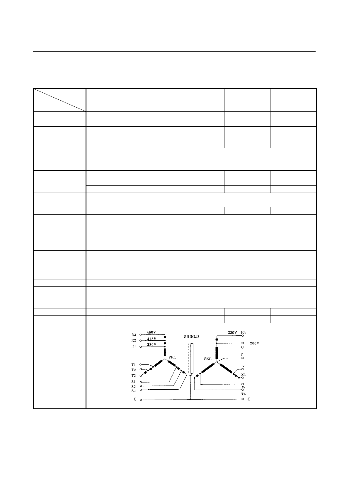
3.ORDERING INFORMATION B-65282EN/06
(
y)
Specifications of power transformers manufactured by FANUC
Power transformer for αi PS
α
Model
α
Item
Ordering drawing
number
FANUC drawing
number
Rated capacity 10kVA 20kVA 30kVA 45kVA 64kVA
Rated primary
voltage
Rated primary current
Rated secondary
voltage
Rated primary current 29A 58A 87A 130A 185A
Voltage regulation at
the secondary
Voltage deviation at
the secondary
Connection Y-Y connection
Insulation Class H (maximum allowable temperature : 180°C)
Ambient temperature 0 to 45°C
Allowable
temperature rise
Relative humidity Max. 95%RH
Type Dry type, natural air cooling type
Dielectric withstand
voltage
Weight Max. 61kg Max. 115kg Max. 165kg Max. 260kg Max. 375kg
Outline drawing Fig.8.1.4(a) Fig.8.1.4(b) Fig.8.1.4(c) Fig.8.1.4(d) Fig.8.1.4(e)
i PS 5.5 αi PS 11 αi PS 15 αi PS 26, 30
A06B-6052-J001 A06B-6044-J006 A06B-6044-J007 A06B-6044-J010 A06B-6044-J015
A80L-0001-0496 A80L-0001-0313 A80L-0001-0314 A80L-0001-0352 A80L-0001-0452
380/415/460VAC
230VAC (The secondary is used as an autotransformer.)
+10% -15%, 50/60±1Hz, 3φ
15A (at 380V) 30A (at 380V) 46A (at 380V) 68A (at 380V) 97A (at 380V)
14A (at 415V) 28A (at 415V) 42A (at 415V) 63A (at 415V) 89A (at 415V)
13A (at 460V) 25A (at 460V) 38A (at 460V) 56A (at 460V) 80A (at 460V)
200/220/230VAC
5%
±3%
135deg
2000VAC, for 1 minute
i PS 37
αi PS 55
(at 45kw output)
(Neutral
point)
Connection diagram
(Primary)
Secondar
- 66 -
Page 91

B-65282EN/06 3.ORDERING INFORMATION
Power transformer for αi PSR
Model
Item
Ordering drawing
number
FANUC drawing
number
Rated capacity 3.5kVA 5kVA 10kVA 20kVA
Rated primary
voltage
Rated primary current
Rated secondary
voltage
Rated primary current 9.6A 13.7A 29A 58A
Voltage regulation at
the secondary
Voltage deviation at
the secondary
Connection Δ-Δ connection or Y-Δ connection Y-Y connection
Insulation
Ambient temperature -20 to 55°C 0 to 45°C
Allowable
temperature rise
Thermostat
Relative humidity Max. 95%RH
Type Dry type, natural air cooling type
Dielectric withstand
voltage
Weight Max. 27kg Max. 36kg Max. 61kg Max. 115kg
Outline drawing Fig.8.1.5(e) Fig.8.1.5(e) Fig.8.1.5(a) Fig.8.1.5(b)
αi PSR 3
(at 2kw output)
A80L-0024-0006 A80L-0026-0003 A06B-6052-J001 A06B-6044-J006
A80L-0024-0006 A80L-0026-0003 A80L-0001-0496 A80L-0001-0313
200/220/230/240VAC , Δ connection
380/415/460/480/550VAC , Y connection
±15%, 50/60Hz±2Hz, 3φ
15A (at 380V) 30A (at 380V)
5.3A (at 380V) 7.6A (at 380V) 14A (at 415V) 28A (at 415V)
13A (at 460V) 25A (at 460V)
210VAC 200VAC
2% 5%
Class B
(maximum allowable temperature: 130°C)
B contact
(operating temperature: 135°C)
2300VAC, for 1 minute 2000VAC, for 1 minute
αi PSR 3
(at 3kw output)
(at 5.5kw output)
230VAC(The secondary is used as an
±3%
(maximum allowable temperature: 180°C)
135deg
αi PSR 5.5
(at 7.5kw output)
380/415/460VAC
autotransformer.)
+10% -15%, 50/60±1Hz, 3φ
Class H
None
αi PSR 5.5
Connection diagram
- 67 -
Page 92

3.ORDERING INFORMATION B-65282EN/06
A
Connecting a power transformer
Power transformers must be set according to the supply voltage used.
(a) Connection points of power transformers for αi PS 5.5, αi PS 11,
αi PS 15, αi PS 26, αi PS 30, and αi PS 37
Supply voltage Connection points at the primary Remarks
380 VAC R - R1, S - S1, T - T1 (380-V tap)
400 VAC R - R1, S - S1, T - T1 (380-V tap)
415 VAC R - R2, S - S2, T - T2 (415-V tap)
440 VAC R - R2, S - S2, T - T2 (415-V tap)
460 VAC R - R3, S - S3, T - T3 (460-V tap)
480 VAC R - R3, S - S3, T - T3 (460-V tap)
Secondary
output
voltage (V)
Voltage regulation (approximately 10V) when the load
varies (0% to 100%) with the 380-VAC tap set
With the 415-VAC tap set With the 460-VAC tap set
C input voltage (V)
CAUTION
1 When installing a transformer in a cabinet, be
careful to ensure that the transformer does not
thermally affect other equipment. For example,
separate the transformer from the other equipment.
2 When installing a transformer outside the cabinet,
make sure that the transformer is not directly
exposed to cutting chips or coolant.
3 If there is a possibility of the transformer falling,
secure the transformer with bolts or similar.
- 68 -
Page 93

B-65282EN/06 3.ORDERING INFORMATION
3.1.3.8 Regenerative discharge unit
Whenever a αi PS
Supply) is used, a regenerative discharge unit must be specified. For
how to select the regenerative discharge unit, see Subsection 4.4.4.
Category Name Ordering number Remarks
αi PSR 3
αi PSR 3, 5.5
Standard
α
i PS
R
See Subsection 8.1.5, "Selecting a Regenerative Discharge Unit" for
details of selection.
(resistance regeneration type Common Power
R
A06B-6089-H510
A06B-6089-H500
A06B-6089-H713
A06B-6089-H711
5.5
A06B-6089-H712
16Ω/100W (at natural cooling)
16Ω/200W (at natural cooling)
16Ω/800W (forced cooling fan
motor is included)
8Ω/800W (forced cooling fan
motor is included)
8Ω/1200W (forced cooling fan
motor is included)
- 69 -
Page 94

3.ORDERING INFORMATION B-65282EN/06
3.1.3.9 Cables
DC link short bar
Category Ordering number Applicable terminal-to-terminal distance
A06B-6078-K801 90mm (86mm - 94mm)
A06B-6078-K803 64mm (60mm - 68mm)
Optional
See 9.3.1.2 for details.
A06B-6078-K842 is used to connect between a 150-mm wide
amplifier (left) and a 300-mm wide amplifier (right).
Cables for connection of amplifiers
Category Ordering number
Optional
NOTE
1 The above table lists the cable for each interface
2 The connection cable for the battery of the absolute
Cables for connection of detectors
Category Ordering number Use Remarks
Optional
Cables for FSSB interface
Category Ordering number
Optional
A06B-6078-K840 154mm (150mm - 158mm)
A06B-6078-K841 300mm (298mm - 302mm)
A06B-6078-K842 150mm (146mm - 154mm)
Cable
length
A06B-6110-K801 200mm 150mm width amplifier
A06B-6110-K802 150mm 90mm width amplifier
A06B-6110-K803 100mm 60mm width amplifier
A06B-6110-K804 400mm 300mm width amplifier
Applicable amplifier width
between amplifiers.
For connection of CXA2A and CXA2B
pulse coder is not included in the cables shown
above. For details, see Subsection 9.3.1.10.
For
A06B-6078-K811
A06B-6078-K814
A06B-6078-K815
A66L-6001-0023#L150R0 15cm
A66L-6001-0023#L300R0 30cm
αiM sensor,
αiMZ sensor
For αi
Positioncoder
Cable
length
Cable length : 7m
Cable length : 7m
Connector figure : Straight
Cable length : 7m
Connector figure : Elbow
Applicable amplifier
width
For between αi SV and
i SV
α
- 70 -
Page 95

B-65282EN/06 3.ORDERING INFORMATION
3.1.3.10 Circuit breaker and magnetic contactor
The circuit breaker and magnetic contactor capacities are determined
by the Common Power Supply specifications. The ordering drawing
numbers and specifications of the circuit breakers and magnetic
contactors are shown below.
When this equipment is to be prepared by the user, it must satisfy the
circuit breaker and magnetic contactor specifications indicated below.
Circuit breaker and magnetic contactor specifications
For αi PS and αi PSR
PS name Circuit breaker 1
αi PSR 3
αi PSR 5.5
αi PS 5.5
αi PS 11
αi PS 15
αi PS 26
αi PS 30
αi PS 37
αi PS 55
20A 20A
30A 30A Note 4)
50A 50A Note 5)
30A to 50A 30A
55A to 75A 55A
70A to 100A 70A
120A to 150A 120A
140A to 200A 140A
175A to to 225A 175A
250A
Circuit
breaker 2
5A
NOTE
1 For the installation positions of the circuit breakers
and magnetic contactor, see Section 1.2.
2 Set the rated voltage of circuit breakers 1 and 2
according to the power supply voltage.
3 The current and voltage of the operation coil of the
magnetic contactor must be within the rating of the
internal contact [CX3 (MCC)] of the αi PS.
For details, see Subsection 9.3.1.5.
i PS
4 When the α
5.5 is used at a rated output
R
capacity of 5.5 kW
5 When the α
i PS
5.5 is used at a rated output
R
capacity of 7.5 kW
6 When the circuit breaker trips, the contact of the
magnetic contactor may be melted. Therefore,
before turning on the circuit breaker again, check to
make sure that the contact of the magnetic
contactor is not melted.
Magnetic
contactor
250A
Remarks
- 71 -
Page 96

3.ORDERING INFORMATION B-65282EN/06
For 400-V input series of αi PS
PS name
αi PS 11HV
αi PS 18HV
αi PS 30HV
αi PS 45HV
αi PS 75HV
αi PS 100HV
Circuit
breaker 1
30A 30A
45A 45A
75A 75A
125A 125A
200A 200A
250A
Circuit
breaker 2
3A 3A
Circuit
breaker 3
Magnetic
contactor
250A
Remarks
NOTE
1 For the installation positions of the circuit breakers
and magnetic contactor, see Section 1.2.
2 Set the rated voltage of circuit breakers 1 and 2
according to the power supply voltage.
3 The current and voltage of the operation coil of the
magnetic contactor must be within the rating of the
internal contact [CX3 (MCC)] of the αi PS.
For details, see Subsection 9.3.1.5.
4 When the circuit breaker trips, the contact of the
magnetic contactor may be melted. Therefore,
before turning on the circuit breaker again, check to
make sure that the contact of the magnetic
contactor is not melted.
- 72 -
Page 97

B-65282EN/06 3.ORDERING INFORMATION
Ordering drawing numbers of circuit breakers
Category Model Ordering number
Optional
αi PSR 3
αi PS 11HV
αi PSR 5.5
αi PS 5.5
αi PS 18HV
αi PS 11
αi PS 15, 30HV
αi PS 45HV
αi PS 26, 30
αi PS 37
αi PS 75HV
αi PS 55, 100HV
For control power A06B-6077-K106 8.1.7(j) Fuji Electric EA33AC/5 Fuji Electric BZ6TBH10C3
A06B-6077-K101 8.1.7(a) Fuji Electric EA53C/30 Fuji Electric BZ6TBH10C3
A06B-6077-K102 8.1.7(b) Fuji Electric EA103C/50 Fuji Electric BZ6TBH10C3
A06B-6077-K103 8.1.7(c) Fuji Electric EA103C/60 Fuji Electric BZ6TBH10C3
A06B-6077-K104 8.1.7(d) Fuji Electric EA103C/75 Fuji Electric BZ6TBH10C3
A06B-6077-K108 8.1.7(e) Fuji Electric EA203B/125 Fuji Electric BZ-TB40B
A06B-6077-K105 8.1.7(f) Fuji Electric EA203B/150 Fuji Electric BZ-TB40B
A06B-6077-K110 8.1.7(g) Fuji Electric EA203B/175 Fuji Electric BZ-TB40B
A06B-6077-K109 8.1.7(h) Fuji Electric EA203B/200 Fuji Electric BZ-TB40B
A06B-6077-K111 8.1.7(i) Fuji Electric EA403B/250 Fuji Electric BZ-TB60B
Outline
drawing
Circuit breaker
specification
Circuit breaker cover
specification
Ordering drawing numbers of magnetic contactors
Category Model Ordering number
Optional
αi PSR 3 ,
αi PS 11HV
αi PSR 5.5, αi PS 5.5
αi PS 18HV
αi PS 11
αi PS 15, 30HV
αi PS 26, 45HV
αi PS 30
αi PS 37, 75HV
i PS 55, 100HV
α
A06B-6077-K121 8.1.7(a) Fuji Electric SC-5-1 Fuji Electric SZ-JC4
A06B-6077-K122 8.1.7(b) Fuji Electric SC-N1 Fuji Electric SZ-N1J
A06B-6077-K123 8.1.7(b) Fuji Electric SC-N2 Fuji Electric SZ-N1J
A06B-6077-K124 8.1.7(c) Fuji Electric SC-N2S Fuji Electric SZ-N2SJ
A06B-6077-K125 8.1.7(d) Fuji Electric SC-N4 Fuji Electric SZ-N4J
A06B-6077-K126 8.1.7(e) Fuji Electric SC-N5 Fuji Electric SZ-N4J
A06B-6077-K128 8.1.7(f) Fuji Electric SC-N7 Fuji Electric SZ-N7J
A06B-6077-K127 8.1.7(g) Fuji Electric SC-N8 Fuji Electric SZ-N8J
NOTE
The coil voltage specification of the magnetic
contactor is 200VAC.
Outline
drawing
Magnetic contactor
specification
Magnetic contactor
cover specification
- 73 -
Page 98

3.ORDERING INFORMATION B-65282EN/06
3.1.3.11 Lightning surge protector
To protect equipment from surge voltages caused by lightning, install
a lightning surge protector between lines and between a line and
ground. For how to install protectors, see Appendix A.
Lightning surge protector specifications
Category Ordering number Specification
For line-to-line
installation :
RAV-781BYZ-2
For line-to-ground
installation :
RAV-781BXZ-4
For line-to-line
installation :
RAV-152BYZ-2A
For line-to-ground
installation :
RAV-801BXZ-4
Integration type for
line-to-line
installation/line-toground
installation:
RCM-601BUZ-4
Optional
A06B-6077-K142
A06B-6077-K143
A06B-6077-K144
Outline
drawing
8.1.9(a)
8.1.9(b)
8.1.9(c)
* The line-to-line or line-to-ground installation type
(A06B-6077-K144) and the integration type
(A06B-6077-K142) are equivalent in performance and
specifications.
Remarks
Manufactured by
Okaya Electric
Industries Co., Ltd.
For 200VAC line
TÜV approved
products
Manufactured by
Okaya Electric
Industries Co., Ltd.
For 400VAC line
TÜV approved
products
Manufactured by
Okaya Electric
Industries Co., Ltd.
For 200VAC line
TÜV approved
products
- 74 -
Page 99

B-65282EN/06 3.ORDERING INFORMATION
3.1.3.12 Noise filter
A noise filter must be installed in the PS input section to satisfy the
requirements of the EMC Directives which are now being enforced in
the EU countries.
Category Model Ordering number
Optional
αi PSR 3
PS 5.5i
αi PSR 5.5
αi PS 11 ,15
αi PS 26, 30
αi PS 37
A06B-6077-K155 30A
A06B-6077-K156 75A
A06B-6077-K157 150A
A06B-6077-K158
Outline
drawing
8.1.10
Rated
output
200A
Specification
3SUP-HL30-ER-6: Okaya Electric
Industries Co., Ltd.
3SUP-HL75-ER-6: Okaya Electric
Industries Co., Ltd.
3SUP-HL150-ER-6: Okaya
Electric Industries Co., Ltd.
3SUP-HL200-ER-6: Okaya
Electric Industries Co., Ltd.
Category Model Ordering number
Optional
αi PSR 3
αi PS 5.5, 11HV
αi PSR 5.5
αi PS 11 ,15
αi PS 18HV, 30HV
αi PS 26, 30
αi PS 45HV
αi PS 37
αi PS 75HV
i PS 55
α
αi PS 100HV
A06B-6110-K160 50A
A06B-6110-K161 80A
A06B-6110-K162 150A
A06B-6110-K163 200A
A06B-6110-K164
Outline
drawing
8.1.10
Rated
output
250A
Specification
NF3050C-VQ: Soshin Electric
Co., Ltd.
NF3080C-VQ: Soshin Electric
Co., Ltd.
NF3150C-VQ: Soshin Electric
Co., Ltd.
NF3200C-VQ:Soshin Electric Co.,
Ltd.
NF3250C-VQ:Soshin Electric Co.,
Ltd.
NOTE
1 A06B-6110-K160 to A06B-6110-K164 (manufactured by Soshin Electric Co.,
Ltd.) are high leakage type filters for neutral grounding. They are not used
for purposes other than neutral grounding.
2 The above models are listed as guidelines for selection. Load currents of the
CNC, amplifier, and other devices flow through the noise filter. Obtain these
load currents, and select a noise filter so that the obtained load currents do
not exceed the rated current of the noise filter.
3.1.3.13 Sensors for servo
αi CZ sensor (separate detector)
Category Name
αi CZ sensor 512AS
Optional
αi CZ sensor 768AS
α
i CZ sensor 1024AS
Ordering
number
A860-2164-T411 512 teeth / 15,000min
A860-2164-T511 768 teeth / 10,000min
A860-2164-T611 1024 teeth / 8,000min
Remarks
-1
-1
-1
- 75 -
Page 100

3.ORDERING INFORMATION B-65282EN/06
3.1.3.14 Sensors for spindle
αi Positioncoder
Name
αi BZ sensor 128
αi BZ sensor 128H
αi BZ sensor 192
αi BZ sensor 192H
αi BZ sensor 256
αi BZ sensor 256S
αi BZ sensor 256H
αi BZ sensor 384
αi BZ sensor 512
Category Name
Optional
αi Positioncoder
Connector kit A06B-6088-K211 Straight type
Ordering
number
A860-2109-T302
αPositioncoder S (analog output type)
Category Name
Optional
αPositioncoder S A860-0309-T352 68, 10,000min-1
Connector kit A06B-6088-K211 Straight type
Ordering
number
αi BZ sensor (compact type)
Ordering number
Waterproof
connector
specification
Non-waterproof
connector
specification
A860-2150-T201 A860-2155-T201 20,000min
A860-2150-T211 A860-2155-T211
A860-2150-T301 A860-2155-T301 20,000min
A860-2150-T311 A860-2155-T311
Num-
ber of
teeth
128
192
A860-2150-T401 A860-2155-T401
A860-2150-T404 A860-2155-T404
256
A860-2150-T411 A860-2155-T411
Maximum
speed
70,000min
40,000min
15,000min
30,000min
A860-2150-T511 A860-2155-T511 384 15,000min
A860-2150-T611 A860-2155-T611 512 10,000min
αi CZ sensor (for built-in spindle motor *1)
Category Name Ordering number Remarks
Optional
αi CZ sensor 512 I
αi CZ sensor 768 I
α
i CZ sensor 1024 I
A860-2161-T411 512 teeth / 15,000min
A860-2161-T511 768 teeth / 10,000min
A860-2161-T611 1024 teeth / 8,000min
αi CZ sensor (for spindle *1)
Category Name Ordering number Remarks
Optional
αi CZ sensor 512 IS
αi CZ sensor 768 IS
α
i CZ sensor 1024 IS
A860-2163-T411 512 teeth / 15,000min
A860-2163-T511 768 teeth / 10,000min
A860-2163-T611 1024 teeth / 8,000min
Remarks
-1
-1
-1
-1
-1
-1
φ82
-1
φ125 φ154.4
-1
φ160 φ205.6
Remarks
68, 10,000min-1
Remarks
Detection ring
Inner
diameter
diameter
φ40 φ52
φ60 φ77.6
φ82
φ88
Outer
φ103.2
-1
-1
-1
-1
-1
-1
- 76 -
 Loading...