

Page 1

C
8
/
-
C
FANU
Series 16/1
Connection Manual
160/180
Model
(Hardware)
B-62753EN/01
Page 2

• No part of this manual may be reproduced in any form.
• All specifications and designs are subject to change without notice.
The export of this product is subject to the authorization of the government of the country
from where the product is exported.
In this manual we have tried as much as possible to describe all the various matters.
However, we cannot describe all the matters which must not be done, or which cannot be
done, because there are so many possibilities.
Therefore, matters which are not especially described as possible in this manual should be
regarded as ”impossible”.
This manual contains the program names or device names of other companies, some of
which are registered trademarks of respective owners. However, these names are not
followed by or in the main body.
Page 3

B–62753EN/01
Table of Contents
1. PREFACE 1. . . . . . . . . . . . . . . . . . . . . . . . . . . . . . . . . . . . . . . . . . . . . . . . . . . . . . . . . . . . . . . . . .
2. CONFIGURATION 3. . . . . . . . . . . . . . . . . . . . . . . . . . . . . . . . . . . . . . . . . . . . . . . . . . . . . . . . . . .
3. INSTALLATION 4. . . . . . . . . . . . . . . . . . . . . . . . . . . . . . . . . . . . . . . . . . . . . . . . . . . . . . . . . . . . .
3.1 ENVIRONMENTAL REQUIREMENTS OUTSIDE THE CABINET 5. . . . . . . . . . . . . . . . . . . . . . . . .
3.2 INSTALLATION REQUIREMENTS OF CNC AND SERVO UNIT 5. . . . . . . . . . . . . . . . . . . . . . . . . .
3.3 POWER CAPACITY 5. . . . . . . . . . . . . . . . . . . . . . . . . . . . . . . . . . . . . . . . . . . . . . . . . . . . . . . . . . . . . . . .
3.4 DESIGN AND INSTALLATION CONDITIONS OF THE MACHINE TOOL
MAGNETIC CABINET 6. . . . . . . . . . . . . . . . . . . . . . . . . . . . . . . . . . . . . . . . . . . . . . . . . . . . . . . . . . . . .
3.5 THERMAL DESIGN OF THE CABINET 8. . . . . . . . . . . . . . . . . . . . . . . . . . . . . . . . . . . . . . . . . . . . . . .
3.5.1 Temperature Rise within the Cabinet 8. . . . . . . . . . . . . . . . . . . . . . . . . . . . . . . . . . . . . . . . . . . . . . .
3.5.2 Cooling by Heat Exchanger 8. . . . . . . . . . . . . . . . . . . . . . . . . . . . . . . . . . . . . . . . . . . . . . . . . . . . . .
3.5.3 Heat Loss of Each Unit 9. . . . . . . . . . . . . . . . . . . . . . . . . . . . . . . . . . . . . . . . . . . . . . . . . . . . . . . . . .
3.6 INSTALLING THE HEAT EXCHANGER 10. . . . . . . . . . . . . . . . . . . . . . . . . . . . . . . . . . . . . . . . . . . . .
3.6.1 Cooling Fin A/B/C 10. . . . . . . . . . . . . . . . . . . . . . . . . . . . . . . . . . . . . . . . . . . . . . . . . . . . . . . . . . . .
3.6.2 Heat Exchanger for CRT/MDI Unit 15. . . . . . . . . . . . . . . . . . . . . . . . . . . . . . . . . . . . . . . . . . . . . . .
3.6.3 The Heat Pipe Type Heat Exchanger 18. . . . . . . . . . . . . . . . . . . . . . . . . . . . . . . . . . . . . . . . . . . . . .
3.6.3.1 Installation 18. . . . . . . . . . . . . . . . . . . . . . . . . . . . . . . . . . . . . . . . . . . . . . . . . . . . . . . . . . . . . . . . . . .
3.7 ACTION AGAINST NOISE 22. . . . . . . . . . . . . . . . . . . . . . . . . . . . . . . . . . . . . . . . . . . . . . . . . . . . . . . . .
3.7.1 Separating Signal Lines 22. . . . . . . . . . . . . . . . . . . . . . . . . . . . . . . . . . . . . . . . . . . . . . . . . . . . . . . .
3.7.2 Ground 24. . . . . . . . . . . . . . . . . . . . . . . . . . . . . . . . . . . . . . . . . . . . . . . . . . . . . . . . . . . . . . . . . . . . .
3.7.3 Connecting the Signal Ground (SG) of the Control Unit 25. . . . . . . . . . . . . . . . . . . . . . . . . . . . . . .
3.7.4 Noise Suppressor 26. . . . . . . . . . . . . . . . . . . . . . . . . . . . . . . . . . . . . . . . . . . . . . . . . . . . . . . . . . . . .
3.7.5 Cable Clamp and Shield Processing 27. . . . . . . . . . . . . . . . . . . . . . . . . . . . . . . . . . . . . . . . . . . . . . .
3.8 CONTROL UNIT 30. . . . . . . . . . . . . . . . . . . . . . . . . . . . . . . . . . . . . . . . . . . . . . . . . . . . . . . . . . . . . . . . .
3.8.1 Configuration and Installation of the Control Unit 30. . . . . . . . . . . . . . . . . . . . . . . . . . . . . . . . . . . .
3.8.2 Battery for Memory Backup 34. . . . . . . . . . . . . . . . . . . . . . . . . . . . . . . . . . . . . . . . . . . . . . . . . . . . .
3.9 CABLE LEAD–IN DIAGRAM 36. . . . . . . . . . . . . . . . . . . . . . . . . . . . . . . . . . . . . . . . . . . . . . . . . . . . . . .
4. TOTAL CONNECTION 49. . . . . . . . . . . . . . . . . . . . . . . . . . . . . . . . . . . . . . . . . . . . . . . . . . . . . .
5. POWER SUPPLY UNIT CONNECTION 56. . . . . . . . . . . . . . . . . . . . . . . . . . . . . . . . . . . . . . . .
5.1 POWER SUPPLY UNIT PANEL LAYOUT 57. . . . . . . . . . . . . . . . . . . . . . . . . . . . . . . . . . . . . . . . . . . . .
5.2 POWER SUPPLY UNIT CONNECTION 59. . . . . . . . . . . . . . . . . . . . . . . . . . . . . . . . . . . . . . . . . . . . . . .
5.3 24V INPUT POWER SOURCE 63. . . . . . . . . . . . . . . . . . . . . . . . . . . . . . . . . . . . . . . . . . . . . . . . . . . . . .
5.3.1 Power Supply for the Control Unit 63. . . . . . . . . . . . . . . . . . . . . . . . . . . . . . . . . . . . . . . . . . . . . . . .
5.3.2 Procedure for Turning on the Power 65. . . . . . . . . . . . . . . . . . . . . . . . . . . . . . . . . . . . . . . . . . . . . . .
5.3.3 Procedure for Turning off the Power 65. . . . . . . . . . . . . . . . . . . . . . . . . . . . . . . . . . . . . . . . . . . . . .
5.4 CABLE FOR POWER SUPPLY TO CONTROL UNIT 66. . . . . . . . . . . . . . . . . . . . . . . . . . . . . . . . . . .
6. CONNECTION OF I/O UNITS TO MACHINE INTERFACE 67. . . . . . . . . . . . . . . . . . . . . . .
6.1 GENERAL 68. . . . . . . . . . . . . . . . . . . . . . . . . . . . . . . . . . . . . . . . . . . . . . . . . . . . . . . . . . . . . . . . . . . . . . .
6.2 CONNECTION OF THE FANUC I/O Link 69. . . . . . . . . . . . . . . . . . . . . . . . . . . . . . . . . . . . . . . . . . . . .
6.2.1 General 69. . . . . . . . . . . . . . . . . . . . . . . . . . . . . . . . . . . . . . . . . . . . . . . . . . . . . . . . . . . . . . . . . . . . .
c–1
Page 4

6.2.2 Connection of FANUC I/O Link by Electric Cable 70. . . . . . . . . . . . . . . . . . . . . . . . . . . . . . . . . . .
6.2.3 Connection of FANUC I/O Link Optical Fiber Cable 71. . . . . . . . . . . . . . . . . . . . . . . . . . . . . . . . .
6.3 CONNECTION OF THE FANUC I/O Unit–MODEL A 73. . . . . . . . . . . . . . . . . . . . . . . . . . . . . . . . . . .
6.3.1 Structure of FANUC I/O Unit–MODEL A 73. . . . . . . . . . . . . . . . . . . . . . . . . . . . . . . . . . . . . . . . . .
6.3.2 Outer Dimensions 73. . . . . . . . . . . . . . . . . . . . . . . . . . . . . . . . . . . . . . . . . . . . . . . . . . . . . . . . . . . . .
6.3.3 Mounting and Dismounting Modules 74. . . . . . . . . . . . . . . . . . . . . . . . . . . . . . . . . . . . . . . . . . . . . .
6.3.4 Connection Diagram 75. . . . . . . . . . . . . . . . . . . . . . . . . . . . . . . . . . . . . . . . . . . . . . . . . . . . . . . . . . .
6.3.5 Connecting Input Power Source 76. . . . . . . . . . . . . . . . . . . . . . . . . . . . . . . . . . . . . . . . . . . . . . . . . .
6.3.6 Grounding 76. . . . . . . . . . . . . . . . . . . . . . . . . . . . . . . . . . . . . . . . . . . . . . . . . . . . . . . . . . . . . . . . . . .
6.3.7 Connecting Signal Cables 77. . . . . . . . . . . . . . . . . . . . . . . . . . . . . . . . . . . . . . . . . . . . . . . . . . . . . . .
6.3.8 Connecting with I/O Modules 81. . . . . . . . . . . . . . . . . . . . . . . . . . . . . . . . . . . . . . . . . . . . . . . . . . . .
6.3.9 Digital Input/Output Module 82. . . . . . . . . . . . . . . . . . . . . . . . . . . . . . . . . . . . . . . . . . . . . . . . . . . .
6.3.10 Correspondence between I/O Signals and Addresses in a Module 84. . . . . . . . . . . . . . . . . . . . . . . .
6.3.11 Number of Points for I/O Unit–MODEL A 85. . . . . . . . . . . . . . . . . . . . . . . . . . . . . . . . . . . . . . . . .
6.4 CONNECTION OF MACHINE OPERATOR’S PANEL INTERFACE UNIT 86. . . . . . . . . . . . . . . . . .
6.4.1 Function Overview 86. . . . . . . . . . . . . . . . . . . . . . . . . . . . . . . . . . . . . . . . . . . . . . . . . . . . . . . . . . . .
6.4.2 System Configuration 88. . . . . . . . . . . . . . . . . . . . . . . . . . . . . . . . . . . . . . . . . . . . . . . . . . . . . . . . . .
6.4.3 Signal Assignment 89. . . . . . . . . . . . . . . . . . . . . . . . . . . . . . . . . . . . . . . . . . . . . . . . . . . . . . . . . . . .
6.4.4 Interface 91. . . . . . . . . . . . . . . . . . . . . . . . . . . . . . . . . . . . . . . . . . . . . . . . . . . . . . . . . . . . . . . . . . . .
6.4.5 PMC Addresses 101. . . . . . . . . . . . . . . . . . . . . . . . . . . . . . . . . . . . . . . . . . . . . . . . . . . . . . . . . . . . . .
6.4.6 Major Connection Precautions 102. . . . . . . . . . . . . . . . . . . . . . . . . . . . . . . . . . . . . . . . . . . . . . . . . .
6.4.7 State of the LEDs on the Machine Operator’s Panel Interface Unit 102. . . . . . . . . . . . . . . . . . . . . .
6.4.8 Connector (on the Cable Side) Specifications 102. . . . . . . . . . . . . . . . . . . . . . . . . . . . . . . . . . . . . .
6.4.9 Machine Operator’s Panel Interface Unit Dimension Diagram
(Including Connector Locations) 104. . . . . . . . . . . . . . . . . . . . . . . . . . . . . . . . . . . . . . . . . . . . . . . .
6.4.10 Machine Operator’s Panel Interface Unit Mounting Dimension Diagram 105. . . . . . . . . . . . . . . . .
6.4.11 Fuse Mounting Position 107. . . . . . . . . . . . . . . . . . . . . . . . . . . . . . . . . . . . . . . . . . . . . . . . . . . . . . .
6.5 CONNECTION OF OPERATOR’S PANEL CONNECTION UNIT 108. . . . . . . . . . . . . . . . . . . . . . . . .
6.5.1 Input Signal Regulations for Operator’s Panel Connection Unit 109. . . . . . . . . . . . . . . . . . . . . . . .
6.5.2 Output Signal Regulations for Operator’s Panel Connection Unit 110. . . . . . . . . . . . . . . . . . . . . . .
6.5.3 Connector Layout for Operator’s Panel Connection Unit 111. . . . . . . . . . . . . . . . . . . . . . . . . . . . .
6.5.4 External View of Operator’s Panel Connection Unit 113. . . . . . . . . . . . . . . . . . . . . . . . . . . . . . . . .
6.6 CONNECTION OF SOURCE OUTPUT TYPE CONNECTION UNIT 114. . . . . . . . . . . . . . . . . . . . . .
6.6.1 Input Signal Specifications for Source Output Type Connection Unit 115. . . . . . . . . . . . . . . . . . . .
6.6.2 Output Signal Specifications for Source Output Type Connection Unit 116. . . . . . . . . . . . . . . . . .
6.6.3 Connector Pin Layout for Source Output Type Connection Unit 120. . . . . . . . . . . . . . . . . . . . . . . .
6.6.4 Dimensions of Source Output Type Connection Unit 122. . . . . . . . . . . . . . . . . . . . . . . . . . . . . . . .
6.7 CONNECTION OF FS0 OPERATOR’S PANEL 124. . . . . . . . . . . . . . . . . . . . . . . . . . . . . . . . . . . . . . . .
6.8 I/O CARD CONNECTION 130. . . . . . . . . . . . . . . . . . . . . . . . . . . . . . . . . . . . . . . . . . . . . . . . . . . . . . . . .
6.8.1 Input Signal Specifications 132. . . . . . . . . . . . . . . . . . . . . . . . . . . . . . . . . . . . . . . . . . . . . . . . . . . . .
6.8.2 Specifications of the Output Signals of the I/O Card (Sink Type) 134. . . . . . . . . . . . . . . . . . . . . . .
6.8.3 Connector Layout for Sink Output Type I/O Card 135. . . . . . . . . . . . . . . . . . . . . . . . . . . . . . . . . . .
6.8.4 Input Signal Connector Pin Layout for Sink Output Type I/O Card 137. . . . . . . . . . . . . . . . . . . . .
6.8.5 Output Signal Connector Pin Layout for Sink Output Type I/O Card 139. . . . . . . . . . . . . . . . . . . .
6.8.6 Address Mapping of I/O Card (Sink Type) 140. . . . . . . . . . . . . . . . . . . . . . . . . . . . . . . . . . . . . . . . .
6.9 SOURCE OUTPUT I/O CARD 145. . . . . . . . . . . . . . . . . . . . . . . . . . . . . . . . . . . . . . . . . . . . . . . . . . . . . .
6.9.1 Input Signal Specifications 145. . . . . . . . . . . . . . . . . . . . . . . . . . . . . . . . . . . . . . . . . . . . . . . . . . . . .
B–62753EN/01
c–2
Page 5

B–62753EN/01
6.9.2 Output Signal Specifications 145. . . . . . . . . . . . . . . . . . . . . . . . . . . . . . . . . . . . . . . . . . . . . . . . . . . .
6.9.3 Connector Layout for Source Output Type I/O Card 147. . . . . . . . . . . . . . . . . . . . . . . . . . . . . . . . .
6.9.4 Input Signal Connector Pin Layout for Source Output Type I/O Card 149. . . . . . . . . . . . . . . . . . .
6.9.5 Output Signal Connector Pin Layout for Source Output Type I/O Card 151. . . . . . . . . . . . . . . . . .
6.9.6 Address map 153. . . . . . . . . . . . . . . . . . . . . . . . . . . . . . . . . . . . . . . . . . . . . . . . . . . . . . . . . . . . . . . .
6.10 USE OF TWO I/O CARDS 159. . . . . . . . . . . . . . . . . . . . . . . . . . . . . . . . . . . . . . . . . . . . . . . . . . . . . . . . .
6.10.1 Specifications of Input and Output Signals 159. . . . . . . . . . . . . . . . . . . . . . . . . . . . . . . . . . . . . . . .
6.10.2 I/O Card Address Map 159. . . . . . . . . . . . . . . . . . . . . . . . . . . . . . . . . . . . . . . . . . . . . . . . . . . . . . . .
6.10.3 Addresses Assigned to Each I/O Card 159. . . . . . . . . . . . . . . . . . . . . . . . . . . . . . . . . . . . . . . . . . . .
7. CONNECTION TO CNC PERIPHERALS 161. . . . . . . . . . . . . . . . . . . . . . . . . . . . . . . . . . . . .
7.1 CRT/MDI UNIT INTERF ACE 162. . . . . . . . . . . . . . . . . . . . . . . . . . . . . . . . . . . . . . . . . . . . . . . . . . . . . .
7.1.1 Outline 162. . . . . . . . . . . . . . . . . . . . . . . . . . . . . . . . . . . . . . . . . . . . . . . . . . . . . . . . . . . . . . . . . . . . .
7.1.2 CRT, PDPor LCD Display Interface 167. . . . . . . . . . . . . . . . . . . . . . . . . . . . . . . . . . . . . . . . . . . . . .
7.1.3 Adjusting the Flat Display 173. . . . . . . . . . . . . . . . . . . . . . . . . . . . . . . . . . . . . . . . . . . . . . . . . . . . .
7.1.4 Contrast Adjustment for Monochrome LCD 174. . . . . . . . . . . . . . . . . . . . . . . . . . . . . . . . . . . . . . .
7.1.5 Keyboard Interface 175. . . . . . . . . . . . . . . . . . . . . . . . . . . . . . . . . . . . . . . . . . . . . . . . . . . . . . . . . . .
7.2 I/O DEVICE INTERFACE 176. . . . . . . . . . . . . . . . . . . . . . . . . . . . . . . . . . . . . . . . . . . . . . . . . . . . . . . . .
7.2.1 RS–232–C Serial Port 176. . . . . . . . . . . . . . . . . . . . . . . . . . . . . . . . . . . . . . . . . . . . . . . . . . . . . . . . .
7.2.2 PPR Connection 177. . . . . . . . . . . . . . . . . . . . . . . . . . . . . . . . . . . . . . . . . . . . . . . . . . . . . . . . . . . . .
7.2.3 Portable Tape Reader Connection 178. . . . . . . . . . . . . . . . . . . . . . . . . . . . . . . . . . . . . . . . . . . . . . . .
7.2.4 FANUC FLOPPY CASSETTE Connection 179. . . . . . . . . . . . . . . . . . . . . . . . . . . . . . . . . . . . . . . .
7.2.5 Connection of Tape Reader without Reels 180. . . . . . . . . . . . . . . . . . . . . . . . . . . . . . . . . . . . . . . . .
7.2.6 Connection of Tape Reader with Reels 181. . . . . . . . . . . . . . . . . . . . . . . . . . . . . . . . . . . . . . . . . . . .
7.3 MANUAL PULSE GENERATOR INTERFACE 182. . . . . . . . . . . . . . . . . . . . . . . . . . . . . . . . . . . . . . . .
7.3.1 Signal Specifications for Manual Pulse Generator 184. . . . . . . . . . . . . . . . . . . . . . . . . . . . . . . . . . .
7.4 REMOTE BUFFER INTERF ACE (RS–232–C) 185. . . . . . . . . . . . . . . . . . . . . . . . . . . . . . . . . . . . . . . . .
7.5 REMOTE BUFFER INTERF ACE (RS–422) 187. . . . . . . . . . . . . . . . . . . . . . . . . . . . . . . . . . . . . . . . . . .
7.6 DNC1 INTERF ACE 189. . . . . . . . . . . . . . . . . . . . . . . . . . . . . . . . . . . . . . . . . . . . . . . . . . . . . . . . . . . . . .
7.6.1 Multi–points Connection 189. . . . . . . . . . . . . . . . . . . . . . . . . . . . . . . . . . . . . . . . . . . . . . . . . . . . . .
7.6.2 1 to 1 Connection 190. . . . . . . . . . . . . . . . . . . . . . . . . . . . . . . . . . . . . . . . . . . . . . . . . . . . . . . . . . . .
7.7 DNC2 INTERF ACE (RS–232–C) 191. . . . . . . . . . . . . . . . . . . . . . . . . . . . . . . . . . . . . . . . . . . . . . . . . . . .
7.8 HIGH SPEED DI SIGNAL INTERFACE 192. . . . . . . . . . . . . . . . . . . . . . . . . . . . . . . . . . . . . . . . . . . . . .
7.8.1 Receiver Input Signal Specifications for High–speed DI Signals 193. . . . . . . . . . . . . . . . . . . . . . .
7.9 SPINDLE INTERFACE 194. . . . . . . . . . . . . . . . . . . . . . . . . . . . . . . . . . . . . . . . . . . . . . . . . . . . . . . . . . .
7.9.1 Serial Spindle Interface 195. . . . . . . . . . . . . . . . . . . . . . . . . . . . . . . . . . . . . . . . . . . . . . . . . . . . . . . .
7.9.2 Analog Spindle Interface 196. . . . . . . . . . . . . . . . . . . . . . . . . . . . . . . . . . . . . . . . . . . . . . . . . . . . . .
7.9.3 Series Spindle Amplifier Interface 197. . . . . . . . . . . . . . . . . . . . . . . . . . . . . . . . . . . . . . . . . . . . .
7.9.4 Position Coder Interface 199. . . . . . . . . . . . . . . . . . . . . . . . . . . . . . . . . . . . . . . . . . . . . . . . . . . . . . .
7.10 SERVO INTERFACE 200. . . . . . . . . . . . . . . . . . . . . . . . . . . . . . . . . . . . . . . . . . . . . . . . . . . . . . . . . . . . .
7.10.1 Outline 200. . . . . . . . . . . . . . . . . . . . . . . . . . . . . . . . . . . . . . . . . . . . . . . . . . . . . . . . . . . . . . . . . . . . .
7.10.2 Servo Amplifier Interface ( series servo amplifier) 201. . . . . . . . . . . . . . . . . . . . . . . . . . . . . . . . .
7.10.3 Serial Pulse Coder Interface 202. . . . . . . . . . . . . . . . . . . . . . . . . . . . . . . . . . . . . . . . . . . . . . . . . . . .
7.10.4 Separate T ype Detector Interface 206. . . . . . . . . . . . . . . . . . . . . . . . . . . . . . . . . . . . . . . . . . . . . . . .
7.10.5 APC Battery Interface 211. . . . . . . . . . . . . . . . . . . . . . . . . . . . . . . . . . . . . . . . . . . . . . . . . . . . . . . . .
7.11 ANALOG SIGNAL INTERFACE 212. . . . . . . . . . . . . . . . . . . . . . . . . . . . . . . . . . . . . . . . . . . . . . . . . . .
7.12 HIGH–SPEED SERIAL BUS (HSSB) INTERFACE 213. . . . . . . . . . . . . . . . . . . . . . . . . . . . . . . . . . . . .
c–3
Page 6

B–62753EN/01
APPENDIX
A. EXTERNAL DIMENSIONS OF EACH UNIT 217. . . . . . . . . . . . . . . . . . . . . . . . . . . . . . . . . . .
B. EXTERNAL DIMENSIONS OF EACH CONNECTOR 261. . . . . . . . . . . . . . . . . . . . . . . . . .
C. 20–PIN INTERFACE CONNECTORS AND CABLES 284. . . . . . . . . . . . . . . . . . . . . . . . . .
D. LIST OF UNIT FOR CE MARKING 293. . . . . . . . . . . . . . . . . . . . . . . . . . . . . . . . . . . . . . . . . .
c–4
Page 7

B–62753EN/01
Series 16
Series 18
Series 160
Series 180
1
1. PREFACE
This manual describes the electrical and structural specifications required
for connecting the CNC control unit to a machine tool. The manual
outlines the components commonly used for F ANUC CNC control units,
as shown in the configuration diagram in Chapter 2, and supplies
additional information on using these components. Refer to individual
manuals for the detailed specifications of each component.
The models covered by this manual, and their abbreviations, are :
Product Name Abbreviations
FANUC Series 16–TC 16–TC
FANUC Series 16–MC 16–MC
Related manuals
FANUC Series 18–TC 18–TC
FANUC Series 18–MC 18–MC
FANUC Series 160–TC 160–TC
FANUC Series 160–MC 160–MC
FANUC Series 180–TC 180–TC
FANUC Series 180–MC 180–MC
The table below lists manuals related to MODEL C of Series 16, Series
18, Series 160 and Series 180.
In the table, this manual is marked with an asterisk(*).
Table 1 Manuals Related
Manual name
DESCRIPTIONS B–62752EN
CONNECTION MANUAL (HARDWARE) B–62753EN
CONNECTION MANUAL (FUNCTION) B–62753EN–1
OPERATOR’S MANUAL (For LATHE) B–62754EN
Specification
Number
*
OPERATOR’S MANUAL (FOR MACHINING CENTER) B–62764EN
MAINTENANCE MANUAL B–62755EN
PARAMETER MANUAL B–62760EN
PROGRAMMING MANUAL
(Macro Compiler / Macro Executer)
FAPT MACRO COMPILER PROGRAMMING MANUAL B–66102E
1
B–61803E–1
Page 8

1. PREFACE
B–62753EN/01
Table 1 Manuals Related
Manual name
FANUC Super CAP T OPERATOR’S MANUAL B–62444E–1
FANUC Super CAP M OPERATOR’S MANUAL B–62154E
FANUC Super CAP M PROGRAMMING MANUAL B–62153E
CONVERSATIONAL AUTOMATIC PROGRAMMING
FUNCTION I FOR LATHE (Series 18–TB)
OPERATOR’S MANUAL
CONVERSATIONAL AUTOMATIC PROGRAMMING
FUNCTION FOR LATHE (Series 15–MODEL B, Series
16 CAPII) OPERATOR’S MANUAL
CONVERSATIONAL AUTOMATIC PROGRAMMING
FUNCTION I FOR MACHINING CENTER
OPERATOR’S MANUAL
Specification
Number
B–61804E–1
B–61804E–2
B–61874E–1
2
Page 9

B–62753EN/01
2
2. CONFIGURA TION
CONFIGURATION
The following figure shows the configuration of the electrical system of
the machine tool with which this control is used.
This manual describes how to connect the units illustrated in this diagram.
The machine tool body, machine operator’s panel, power magnetic
circuit, and sensor/actuator are specific to the machine tool and are the
builder’s responsibility. This manual does not cover the internal
connection of these units to the machine tool. The numbers in parentheses
shown in the diagram are section references for this manual.
Machine tool magnetic cabinet
Heat
exchanger
(3.6)
Control unit
(3.8)
(5)
Multi–tap
transformer for
the control unit
(Note1)
Operator’s
panel interface
(6.4, 6.5)
Manual pulse generator
(7.3)
I/O unit
(6.2, 6.3, 6.7–6.9)
Spindle
amplifier
(7.9)
CRT/MDI
unit
Machine
operator’s
panel
Relay connector (7.2)
Power
magnetic
circuit
Servo
amplifier
(7.10)
(Note 2)
(Note 2)
I/O device
Sensor /
actuator
Servo
motor
Spindle
motor
Power
supply
Distribution
board
Note 1 Refer to the ”FANUC I/O Unit Model A Connecting Maintenance Manual (B-61813E)”.
Note 2 Refer to the following manuals:
“FANUC AC Servo Motor α Series Descriptions (B-65142E)”
“FANUC AC Spindle Motor α Series Descriptions (B-65152E)”
“FANUC CONTROL MOTOR AMPLIFIER α Series Descriptions (B–65162E)”
(7.4, 7.5, 7.6)
Host computer
3
Page 10

3. INSTALLATION
INSTALLA TION
3
B–62753EN/01
4
Page 11

B–62753EN/01
Room temperature
Relative humidity
Room temperature
3. INSTALLATION
3.1
ENVIRONMENTAL REQUIREMENTS OUTSIDE THE CABINET
The peripheral units, such as the control unit and CRT/MDI, have been
designed on the assumption that they are housed in closed cabinets. In
this manual “cabinet” refers to the following:
Cabinet manufactured by the machine tool builder for housing the
control unit or peripheral units;
Cabinet for housing the flexible turnkey system provided by F ANUC;
Operation pendant, manufactured by the machine tool builder, for
housing the CRT/MDI unit or operator’s panel.
Equivalent to the above.
The environmental conditions when installing these cabinets shall
conform to the following table. Section 3.4 describes the installation and
design conditions of a cabinet satisfying these conditions.
In operation 0 to 45
In storage or transportation –20 to 60
Change in
temperature
Vibration In operation: 0.5G or less
Environment
1.1°C/minute max.
Normal 75% or less
Temporary (within 1 month) 95% or less
Normal machine shop environment
(The environment must be considered if the cabinets
are in a location where the density of dust, coolant,
and/or organic solvent is relatively high.)
3.2
INSTALLATION
REQUIREMENTS OF
CNC AND SERVO
UNIT
3.3
POWER CAPACITY
In operation 0°C to +55°C
In storage or transportation –20°C to +60°C
Relative humidity 95% RH or less (no condensation)
Vibration 0.5 G or less
Environment
The unit shall not be exposed direct to cutting oil, lubricant or cutting chips.
The power capacity of the CNC control unit, which in this section means
the specification required for the power supply , is obtained by adding the
power capacity of the control section and the power capacity of the servo
section.
The power capacity of the control section includes the power capacity of
the control unit, CRT/MDI, I/O unit, and operator’s panel interface.
Power capacity of
the control section
When power supply AI is used and AC output terminals CP2 and CP3 are not used.
When power supply AI is used and AC output terminals CP2 and CP3 are used.
When power supply BI is used and AC output terminals CP2 and CP3 are not used.
When power supply BI is used and AC output terminals CP2 and CP3 are used.
0.3kV A
0.8kV A
0.5kV A
1.0kV A
Power capacity of
the servo section
5
Depends on servo motor type.
Page 12

3. INSTALLATION
B–62753EN/01
3.4
DESIGN AND
INSTALLATION
CONDITIONS OF THE
MACHINE TOOL
MAGNETIC CABINET
When a cabinet is designed, it must satisfy the environmental conditions
described in Section 3.1. In addition, the magnetic interference on the
CRT screen, noise resistance, and maintenance requirements must be
considered. The cabinet design must meet the following conditions :
D The cabinet must be fully closed.
The cabinet must be designed to prevent the entry of airborne
dust,coolant,and organic solvent.
Cabinets that let in air may be designed for the servo amplifier and
servo transformer provided that they :
- Use an air filter on the air inlet ;
- Place the ventilating fan so that it does not blow air directly toward
the unit;
- Control the air flow so that no dust or coolant enters the air outlet
D The cabinet must be designed to maintain a difference in temperature
of 10°C or less between the air in the cabinet and the outside air when
the temperature in the cabinet increases.
See Section 3.5 for the details on thermal design of the cabinet.
D A closed cabinet must be equipped with a fan to circulate the air
within.
The fan must be adjusted so that the air moves at 0.5 m/sec along the
surface of each installed unit.
CAUTION : If the air blows directly from the fan to the unit, dust
easily adheres to the unit. This may cause the unit to fail.
D For the air to move easily , a clearance of 100 mm is required between
each unit and the wall of the cabinet.
D Packing materials must be used for the cable port and the door in order
to seal the cabinet.
Because the CR T unit uses a voltage of approximately 11 kV, airborne
dust gathers easily . If the cabinet is insufficiently sealed, dust passes
through the gap and adheres to the unit. This may cause the insulation
of the unit to deteriorate.
D The CRT/MDI unit must be installed in a location where coolant
cannot be poured directly on it. The unit does have a dust–proof front
panel.
D Noise must be minimized.
As the machine and the CNC unit are reduced in size, the parts that
generate noise may be placed near noise–sensitive parts in the
magnetics cabinet.
The CNC unit is built to protect it from external noise. Cabinet design
to minimize noise generation and to prevent it from being transmitted
to the CNC unit is necessary. See section 3.7 for details of noise
elimination/management.
D The units must be installed or arranged in the cabinet so that they are
easy to inspect and maintain.
6
Page 13

B–62753EN/01
3. INSTALLATION
The CRT screen can be distorted by magnetic interference.
Arranging magnetic sources must be done with care.
If magnetic sources (such as transformers, fan motors,
electromagnetic contactors, solenoids, and relays) are located near the
CRT display, they frequently distort the display screen. To prevent
this, the CR T display and the magnetic sources generally must be kept
300 mm apart. If the CRT display and the magnetic sources are not
300 mm apart, the screen distortion may be suppressed by changing
the direction in which the magnetic sources are installed.
The magnetic intensity is not constant, and it is often increased by
magnetic interference from multiple magnetic sources interacting
with each other. As a result, simply keeping the CR T and the magnetic
sources 300 mm apart may not be enough to prevent the distortion.
If they cannot be kept apart, or if the CRT screen remains distorted
despite the distance, cover the screen with a magnetic shield.
The installation conditions of the I/O unit must be satisfied.
T o obtain good ventilation in the module, the I/O unit must be installed
in the direction shown in the following figure. Clearances of 100 mm
or more both above and below the I/O unit are required for wiring and
ventilation.
Equipment radiating too much heat must not be put below the I/O unit.
Top
Bottom
I/O base unit
(No screws or protrusions shall
extend from the bottom of this
unit.)
7
Page 14

3. INSTALLATION
B–62753EN/01
3.5
THERMAL DESIGN OF THE CABINET
3.5.1
The purpose of the thermal design of the cabinet is to limit the difference
in temperature between the air in the cabinet and the outside air to 10°C
or less when the temperature in the cabinet increases.
The internal air temperature of the cabinet increases when the units and
parts installed in the cabinet generate heat. Since the generated heat is
radiated from the surface of the cabinet, the temperature of the air in the
cabinet and the outside air balance at certain heat levels. If the amount
of heat generated is constant, the larger the surface area of the cabinet, the
less the internal temperature rises. The thermal design of the cabinet
refers to calculating the heat generated in the cabinet, evaluating the
surface area of the cabinet, and enlarging that surface area by installing
heat exchangers in the cabinet, if necessary. Such a design method is
described in the following subsections.
The cooling capacity of a cabinet made of sheet metal is generally 6 W/°C
per 1m
cabinet having a surface area of 1 m
cabinet rises by 1°C. In this case the surface area of the cabinet refers to
the area useful in cooling , that is, the area obtained by subtracting the area
of the cabinet touching the floor from the total surface area of the cabinet.
There are two preconditions : The air in the cabinet must be circuited by
the fun, and the temperature of the air in the cabinet must be almost
constant.The following expression must then be satisfied to limit the
difference in temperature between the air in the cabinet and the outside air
to 10°C or less when the temperature in the cabinet rises:
Internal heat loss P [W]
6[W/m
For example, a cabinet having a surface area of 4m
of 24W/°C. T o limit the internal temperature increase to 10°C under these
conditions, the internal heat must not exceed 240W . If the actual internal
heat is 320W, however, the temperature in the cabinet rises by 13°C or
more. When this happens, the cooling capacity of the cabinet must be
improved using the heat exchanger described next.
2
surface area, that is, when the 6W heat source is contained in a
2
⋅°C] × surface area S[m2]×10[°C] of rise in temperature
2
, the temperature of the air in the
2
has a cooling capacity
3.5.2
If the temperature rise cannot be limited to 10°C by the cooling capacity
of the cabinet, a heat exchanger must be added. The heat exchanger
forcibly applies the air from both the inside and outside of the cabinet to
the cooling fin to obtain effective cooling. The heat exchanger enlarges
the surface area. Section 3.7 explains five heat exchangers supplied by
FANUC. Select one of these according to the application.
If cooling fin A is used for the cabinet, the total cooling capacity of a
cabinet having a surface area of 4 m
as follows :
6W/m
The calculated value verifies that even if the internal heat is 320 W, the
temperature rise can be limited to less than 10°C.
See Section 3.6 for installing the heat exchanger.
2
⋅°C × 4m2 + 9.1W/°C= 33.1W/°C
8
2
in the example above is improved
Page 15

B–62753EN/01
O erator s
3.5.3
Heat Loss of Each Unit
Name Heat
loss
Basic unit (2 slots) 60W Power supply AI
Basic unit (4 slots) 60W Power supply AI
Basic unit (6 slots) 80W Power supply BI
Basic unit (8 slots) 80W Power supply BI
Main CPU board 20W
Control unit
CRT/MDI
p
panel
I/O Unit AIF01A, AIF01B 1.2W
Option 1 board 15W
Option 2 board 15W
Option 3 board 15W
I/O card (Sink type, Source type) 15–20W*1
Robot control board 15W
9″ monochrome CRT/MDI 14W For small type
9″ color CRT/MDI 40W
9″ monochrome PDP/MDI 20W
8.4″ color LCD/MDI 20W
9.5″ color LCD/MDI 20W
14″ color CRT/MDI 70W
Operator’s panel connection unit 30W
’
Machine operator’s panel interface unit
AID32A, AID32B 1.2W + 0.23W number
AID16C, AID16D 0.1W + 0.21W number
AID32E, AID32F 0.1W + 0.23W number
24W
of ON points
of ON points
of ON points
3. INSTALLATION
Remarks
CRT/MDI and standard type CRT/MDI
Refer to FANUC CONTROL MOTOR AMPLIFIER α Series
Descriptions (B–65162E) for heat loss of servo amplifier.
*1 : 5W for 5V type ; 0.175W per pin that is turned on for 24V.
9
Page 16
3. INSTALLATION
B–62753EN/01
3.6
INSTALLING THE HEAT EXCHANGER
3.6.1
Table 3.6 lists the heat exchangers.Cooling fins A, B and C are not
provided with a fan. Note that a fan motor is required for any of these
cooling fins when it is used as a heat exchanger.
Table 3.6 List of Heat Exchangers
Name
Cooling fin A A02B–0053–K303 9.1W/°C 196 90 1000mm
Cooling fin B A02B–0053–K304 10.1W/°C 444 90 650mm
Cooling fin C A02B–0053–K305 25.2W/°C 560 90 970mm
Heat pipe type
heat exchanger
Heat exchanger for
CRT/MDI unit
Ordering
specification
A02B–0094–C901 9.0W/°C 226 132 415mm
A02B–0060–K401 5.0W/°C 590 86 480mm
Cooling
capacity
Size
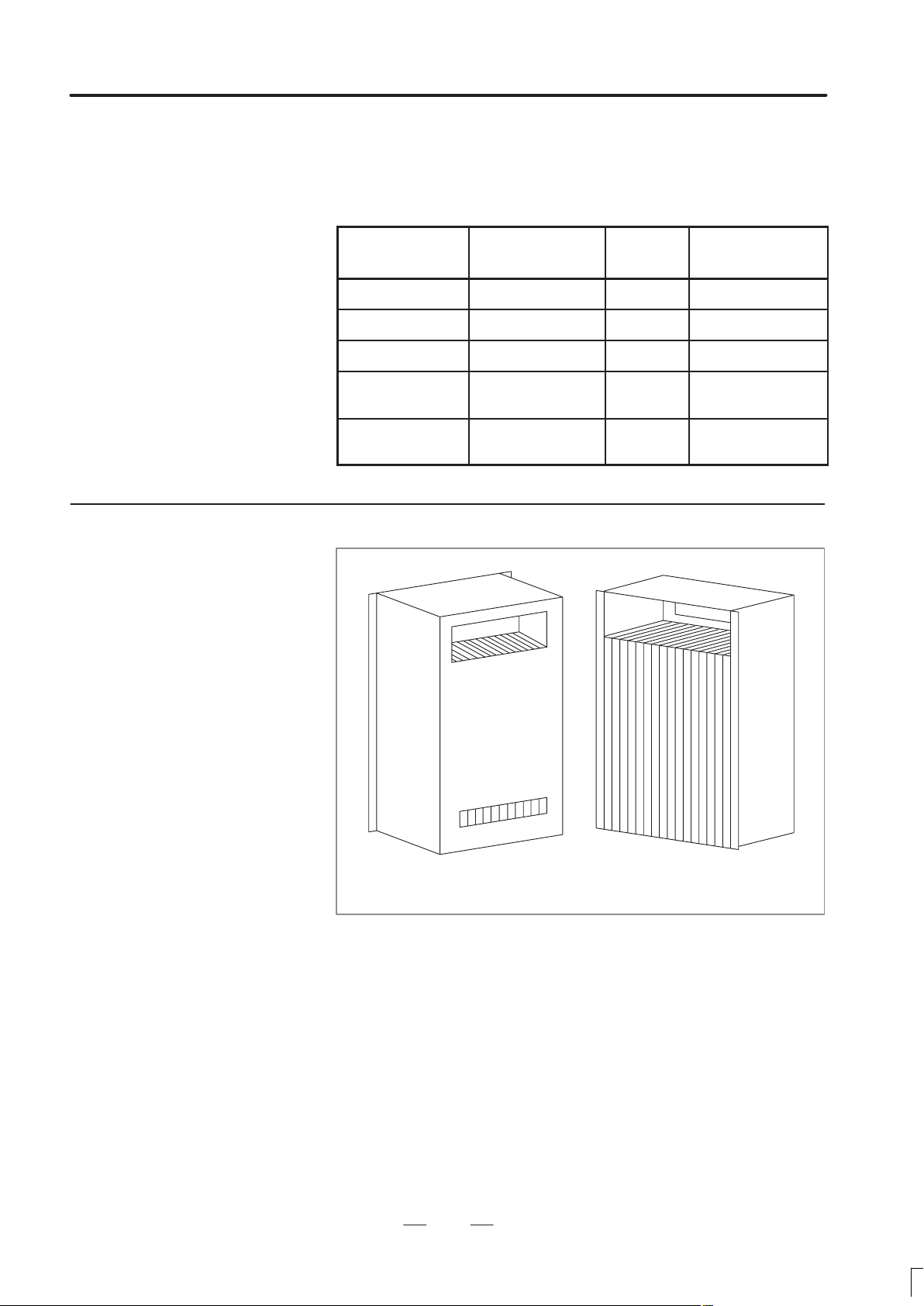
The cooling fin is shown in Fig. 3.6.1 (a).
Viewed from cabinet mounting side
Fig. 3.6.1(a) External view of cooling fin
10
Page 17

B–62753EN/01
3. INSTALLATION
It is installed in a cabinet made by the machine tool builder.
Cooling fin
Inside air
flow
Outside
air flow
Fig. 3.6.1(b) Internal view of cooling fin
Cabinet
The cooling fin can be installed in two ways, as shown in Fig.3.6.1(b).
The following lists the general precautions to be observed when using the
cooling fins :
D The fans are not included with the cooling fin. They should be
provided by the machine tool builder.
D Bring in the outside air from the bottom and exhaust the hot air from
the top.
D The inside air may flow from top to bottom or bottom to top. However,
generally decide the direction as follows :
- Bring in the air near high heat loss components.
- Exhaust the air toward the most important components to be
cooled.
D For the cooling fin to display the specified cooling capacity, the air
inside the cooling fins must flow at a velocity of 2.5 m/sec or greater.
(velocity of air flow measurement)
11
Set the slit to the intake side and
measure the velocity at the slit.
Page 18
3. INSTALLATION
B–62753EN/01
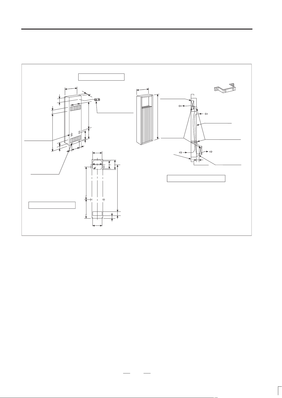
Generally , install the cooling fins to the door. But be sure that the door
does not bend when installing the cooling fin. The cooling fins are
equipped with packing.
External dimensions
70
4–M4
mounting
685
screw for
cooling fins
4–M4
mounting screw
for fan mounting
plate
PANEL CUT DRAWING
100
70
24.7
45
5
196
136
136
220
24.7
5
570
260
90
Terminal block for
fan motor G–04
(Attached to the
570
cooling fins. Its
height is 20mm)
260
10
150
168
C15
164
180188
45
183
Fan mounting
plate
Mounting metal for
cooling fins (sheet metal about 3mm thick).
1000
Fan motor
Cooling fins
Mounting metal
for cooling fins
Door
Mounting plate
40
for fan motor
Mounting diagram (example)
770
Note1 Fan motor, mounting plate for fan motor and mounting
70
metal for cooling fins are not attached to the cooling
fins.
So, prepare them at the machine tool builder.
Note2 Use two fan motors with about 50W power.
Note3 Weight : 6.5kg
Fig. 3.6.1(c) External dimension and mounting method of cooling fin A (02B–0053–K303)
12
Page 19

B–62753EN/01
3. INSTALLATION
650
Mounting
hole for
fan motor
4–M4
4–M4
(Mounting hole for
fan motor)
6–6 dia. hole or
M5 stud bolt
Stud hole
(Make a hole 5 dia. for
fan motor)
External dimensions
444
350
370
1
418
0
2
4
300
358
60
300
135
25
90
72
60
435
124
116
14
1
2
10
0
4
72
6
Terminal block for fan motor G–04
(Attached to the cooling fins.
370
350
Hole
400
Hole
432
Its height is 20mm)
External shape
of cooling fins
116 124
30
Mounting stud for cooling fins
(2 studs are attached for the top and the bottom)
Mounting plate
for fan motor
Fan motor
6–6 dia
Mounting hole
432
25
300
300
25
6
Mounting diagram (example)
Cooling fins
Mounting plate
for fan motor
5 dia
Note1 Fan motor and mounting plate are not attached to the
Note2 Use four fan motors with about 20W power.
cooling fins. So, prepare them, at the machine tool builder.
Note3 Weight : 7.5kg
Fig. 3.6.1(d) External dimension and mounting method of cooling fin B (A02B–0053–K304)
13
Page 20

3. INSTALLATION
B–62753EN/01
970
6–M4
Mounting
hole for fan
motor
37
6
5M–4
(Mounting hole for
fan motor)
6–6 dia. hole or M5
stud bolt
Panel cut drawing
560
266
213
266
233
520
335
315
287
10
External dimensions
90
115
60
695
Terminal block
for fan motor
G–04
210
37
60
6
(Attached to the
cooling fins. Its
10
height is 20mm)
35
548
440
170
155
430
5 DIA
(This hole
combines
mounting hole
and stud hole.)
514
External shape of
cooling fins
775
Note1 Fan motor and mounting plate for fan motor are
60
25
Note2 Use two fan motors with about 40W power.
Note3 Weight : 13.5kg
Mounting stud for cooling fins
(Attached to the cooling fins)
Mounting plate
for fan motor
23
335
315
Cooling fins
Fan motor
287
8–6 dia.
mounting hole
548
6
10
6
Door
40
not attached to the cooling fins. Prepare them at the
machine tool builder.
Fig. 3.6.1(e) External dimension and mounting method of cooling fin C (A02B–0053–K305)
14
Page 21

B–62753EN/01
3.6.2
Heat Exchanger for
CRT/MDI Unit
3. INSTALLATION
External dimensions of
finger guard
+0.5
"
1
5
364
1.6
20
–0
4.3
81 5
External dimensions of
external cooling fun
+0.5
38
+0.3
+0.3
6
6
8–43
Hole
+1.5
–0.5
152.5
AIR
FLOW
Lot No.
119.5
104.8
+0.5
+0.3
Weight : 0.65kg
+0.3
104.8
+0.5
119.5
Air inlet
22022020
Packing
480
Power terminal
M4 screw
200VAC 50Hz
200/220VAC
60Hz
48W
Air outlet
378
6–6
390
Connector for
external cooling fan
Cooling fin : About 6kg
(Excluding attached parts)
Note ) External cooling fan and finger guard are attached beside cooling fin.
Fig. 3.6.2(a) External dimensions of external cooling fan and cooling unit for CRT/MDI
(A02B–0060–K401 (Note))
15
Page 22

3. INSTALLATION
B–62753EN/01
Heat exchanger
Outside Inside
23 15=345
Air outlet
15
Air outlet
50 10
Main body of
480
(1)
220
22020 20
378
390
10
(4)
(3)
Air inlet
(1)
70
Prepare
mounting
screws and
mounting panel
External cooling fan
(attached)
Finger guard
(attached)
heat exchanger
(1) Use M5 screws to mount the heat exchanger.
(2) Be careful with air flow when securing the external cooling fan.
(3) Prepare a mounting panel for external cooling fan and install the panel where it can be exchanged externally .
(4) Drill mounting holes for external cooling fan and air outlet on heat exchanger mounting panel.
Fig. 3.6.2(b) Mounting methods of heat exchanger for CRT/MDI
16
Page 23

B–62753EN/01
3. INSTALLATION
Horizontal type CRT/MDI only
Inside
Side view
CRT/MDI
Heat exchanger
370
Top view
Min
35
Outside
Horizontal type CRT/MDI and
machine operator’s panel
370
Min
35
Vertical type CRT/MDI only
370
Min
35
Refer to these figures for allocation of CRT/MDI and heat exchanger
Fig. 3.6.2(c) Allocation of 14″color CRT/MDI and heat exchanger
17
Page 24

3. INSTALLATION
ificati
3.6.3
B–62753EN/01
3.6.3.1
Installation
Specifications
The heat pipe type heat exchanger is used for cooling the airtight cabinet
of small sized electronic devices. It is a compact, lightweight, and
heat–efficient unit. Because the fan is built–in, it is used simply by
installing it, performing the ”panel cut’ operation.
Installation format Installation type in board
Fan
spec
Weight (kg) 4
Color Munsell signal N1.5
ons
Order specifications
Cooling ability (W/°C) 9 (50Hz when operating)
Voltage (V) 200VAC
Frequency (Hz) 50 60
Rating current (A) 0.28 0.24
Rating input (W) 28 26
Heat exchanger A02B–0094–C901
Remarks
A filter is installed on the outside air inhalation side.
The installation board thickness is the standard 1.6 t.
When a fan motor and filter are necessary for maintenance, prepare
them separately.
Fan motor specifications
A90L–0001–0219#A
Filter specifications
A250–0689–X004
If the heat exchanger is installed near the CR T, screen distortion may
occur due to magnetic flux leakage from the fan motor.
18
Page 25

B–62753EN/01
External dimensions
3. INSTALLATION
17.5
190
6–6 dia.
415
190
17.5
3
Power
source
terminal M4
AIR
FLOW
Earth
terminal
M4
External
fan unit
Internal
fan unit
AIR
FLOW
6
216
226
6
22.4
85
22.4
1.6
(Installation board thickness)
199
8.5
19
Page 26

3. INSTALLATION
Panel cut dimensions
B–62753EN/01
180
2.5
190
190
HOLE
187.5
6
175
3–5 dia.
6–6 dia. or stud welder (M4)
214
20
Page 27

B–62753EN/01
3. INSTALLATION
Installation method
Please install the heat exchanger by the following sequence:
1 T ake out the external fan unit from the heat exchanger main unit. (Fig.
1)
Detach the external fan unit installation screws A (2 pieces), take out
the unit from the main unit by sliding it down, and detach the earth
cable and the power cable to the fan. Also detach the installation screw
B (1 piece).
2 Install the heat exchanger main unit in the installation section which
has been panel cut. (Fig. 2)
When fastening down the heat exchanger main unit with the screws,
first, temporarily secure the panel and the heat exchanger main unit
with the installation screw B, which was taken out in 1). After that,
secure the main unit by the installation screws. In this case, the
external fan unit installation screw holes should be aligned with the
main unit screw holes. (Please provide the installation screws for the
heat exchanger main unit.)
Because this product is composed of plastic, set the value shown
below for the screw tightening torque.
Heat exchanger main unit (M4 screw) : 11 kgf.cm
External fan unit (M3 screw) : 5 kgf.cm
3 Connect the power cable and the earth cable to the external fan unit (the
unit detached in 1), and secure the installation screw A to the main unit
from the outside.
The installation is now complete.
Heat exchanger
main unit
Fan power cable
(detach the connector)
External fan unit
Installation screw B (1)
Earth cable (if the installation screw on the
fan side is detached, it can be taken out.)
Fig. 1 Take out the external fan unit from the
heat exchanger main unit
Installation screws A (2)
Installation
screw
Fig. 2 Install the heat exchanger main unit and
Installation screw B (1)
Installation panel
the external fan unit
21
Page 28

3. INSTALLATION
B
and C, or cover grou A with an
s ark killers or diodes with the
y
ith
G
ibl
ith
S
B
cessing in Section 3.7.5
B–62753EN/01
3.7
ACTION AGAINST NOISE
3.7.1
Separating Signal Lines
The CNC has been steadily reduced in size using surface–mount and
custom LSI technologies for electronic components. The CNC also is
designed to be protected from external noise. However, it is difficult to
measure the level and frequency of noise quantitatively, and noise has
many uncertain factors. It is important to prevent both noise from being
generated and generated noise from being introduced into the CNC. This
precaution improves the stability of the CNC machine tool system.
The CNC component units are often installed close to the parts generating
noise in the power magnetics cabinet. Possible noise sources into the
CNC are capacitive coupling, electromagnetic induction, and ground
loops.
When designing the power magnetics cabinet, guard against noise in the
machine as described in the following section.
The cables used for the CNC machine tool are classified as listed in the
following table:
Process the cables in each group as described in the action column.
Group Signal line Action
Primary AC power line
Secondary AC power line
AC/DC power lines (containing
the power lines for the servo and
A
spindle motors)
AC/DC solenoid
AC/DC relay
DC solenoid (24VDC)
DC relay (24VDC)
DI/DO cable between the CNC
B
and power magnetics cabinet
DI/DO cable between the CNC
and machine
Cable between the CNC and servo amplifier
Cable for position and velocity
feedback
Cable between the CNC and
spindle amplifier
Cable for the position coder
Cable for the manual pulse gen-
C
erator
Cable between the CNC and the
CRT/MDI
RS–232–C and RS–422 interface
cable
Cable for the battery
Other cables to be covered with
the shield
Bind the cables in group A separately (Note 1) from groups
p
electromagnetic shield (Note 2).
See Section 3.7.4 and connect
p
solenoid and relay .
Connect diodes with DC solenoid and relay .
Bind the cables in group B separately from group A, or cover
group B w
shield.
Separate group B as far from
roup C as poss
It is more desirable to cover
group B with the shield.
Bind the cables in group C separately from group A, or cover
group C w
shield.
eparate group C as far from
Group B as possible.
e sure to perform shield pro-
an electromagnetic
e.
an electromagnetic
.
22
Page 29

B–62753EN/01
3. INSTALLATION
Notes
1. The groups must be 10 cm or more apart from one another
when binding the cables in each group.
2. The electromagnetic shield refers to shielding between
groups with grounded steel plates.
Cabinet
Spindle
amp.
Servo
amp.
Cable of group A
Control
unit
Cable of group B, C
Duct
Section
Group A Group B, C
Cover
To operator’s
panel,
motor, etc.
23
Page 30

3. INSTALLATION
B–62753EN/01
3.7.2
Ground
The following ground systems are provided for the CNC machine tool:
Signal ground system (SG)
The signal ground (SG) supplies the reference voltage (0V) of the
electrical signal system.
Frame ground system (FG)
The frame ground system (FG) is used for safety, and suppressing
external and internal noises. In the frame ground system, the frames,
cases of the units, panels, and shields for the interface cables between
the units are connected.
System ground system
The system ground system is used to connect the frame ground
systems connected between devices or units with the ground.
Signal ground system
Power
magnetics
unit
Servo
amplifier
CNC
control
unit
Frame ground system
System ground system
Operator’s
panel
Machine
tool
Power
magnetics
cabinet
Distribution board
Connect the signal ground with the frame ground (FG) at only one
place in the CNC control unit.
The grounding resistance of the system ground shall be 100 ohms or
less (class 3 grounding).
The system ground cable must have enough cross–sectional area to
safely carry the accidental current flow into the system ground when
an accident such as a short circuit occurs.
(Generally, it must have the cross–sectional area of the AC power cable
or more.)
Use the cable containing the AC power wire and the system ground
wire so that power is supplied with the ground wire connected.
24
Page 31

B–62753EN/01
3. INSTALLATION
3.7.3
Connecting the Signal
Ground (SG) of the
Control Unit
Connect the 0 V line of the electronic circuit in the control unit with the
ground plate of the cabinet via the signal ground (SG) terminal.
The SG terminal is located on the printed circuit board at the rear of the
control unit.
Control unit
PCB
Signal
ground
(SG)
M4
(Only thread
hole)
M3
(With thread)
SG
M3
Ground plate of
the cabinet
Ground cable
Wire with a sectional
area 2mm
2
or more
System ground
Ground cable
25
Page 32

3. INSTALLATION
B–62753EN/01
3.7.4
Noise Suppressor
The AC/DC solenoid and relay are used in the power magnetics cabinet.
A high pulse voltage is caused by coil inductance when these devices are
turned on or off.
This pulse voltage induced through the cable causes the electronic circuits
to be disturbed.
Use a spark killer consisting of a resistor and capacitor in series. This
type of spark killer is called a CR spark killer.(Use it under AC)
(A varistor is useful in clamping the peak voltage of the pulse voltage,
but cannot suppress the sudden rise of the pulse voltage. FANUC
therefore recommends a CR spark killer.)
The reference capacitance and resistance of the spark killer shall
conform to the following based on the current (I (A)) and DC
resistance of the stationary coil:
1) Resistance (R) : Equivalent DC resistance of the coil
2) Capacitance (C) :
10
2
I
2
I
∼
20
(µF)
I : Current at stationary state of the coil
RC
Equivalent circuit of the spark killer
AC
relay
Spark killer
Mount the noise eliminator near a motor or a relay coil.
Note) Use a CR–type noise eliminator . Varistor–type noise eliminators
Diode (used for direct–current circuits)
–
clamp the peak pulse voltage but cannot suppress a sharp
rising edge.
Diode
DC relay
+
Use a diode which can withstand a
voltage up to two times the applied
voltage and a current up to two times
the applied current.
Spark killer
Motor
26
Page 33

B–62753EN/01
3. INSTALLATION
3.7.5
Cable Clamp and
Shield Processing
The CNC cables that require shielding should be clamped by the method
shown below. This cable clamp treatment is for both cable support and
proper grounding of the shield. To insure stable CNC system operation,
follow this cable clamp method.
Partially peel out the sheath and expose the shield. Push and clamp by
the plate metal fittings for clamp at the part. The ground plate must be
made by the machine tool builder, and set as follows :
Ground plate
Cable
Metal fittings
for clamp
40 mm to 80 mm
Fig. 3.7.5(a) Cable clamp (1)
27
Page 34

3. INSTALLATION
B–62753EN/01
Machine side
installation
board
Control unit
Ground plate
Metal fittings
for clamp
Shield cover
Fig. 3.7.5(b) Cable clamp (2)
Prepare ground plate like the following figure.
Hole for securing metal fitting clamp
Mount screw hole
Fig. 3.7.5(c) Ground plate
Ground terminal
(grounded)
For the ground plate, use a metal plate of 2 mm or thicker, which surface
is plated with nickel.
28
Page 35

B–62753EN/01
3. INSTALLATION
8mm
12mm
20mm
Fig. 3.7.5(d) Ground plate holes
(Reference) Outer drawings of metal fittings for clamp.
Max. 55mm
Ground
plate
6mm
Fig. 3.7.5(e) Outer drawings of metal fittings for clamp
Ordering specification for metal fittings for clamp
A02B–0083–K301 (5 pieces)
28mm
17mm
29
Page 36

3. INSTALLATION
3.8
CONTROL UNIT
B–62753EN/01
3.8.1
Configuration and
Installation of the
Control Unit
Background
graphic
board
Background
graphic
CPU
(For Super
CAP M)
MMC
board
MMC–IV
CPU
Hard disk
drive
Floppy disk
drive
Printer
Keyboard
RS–232–C
Ethernet
Communication
CPU
High
precision
contour
control
64–bit
RISC CPU
OSI
board
RISC
board
Printed circuit boards are mounted in a rack equipped with several slots.
There are three types of printed circuit boards depending on the models
as shown in Fig.3.8.1 (a), Fig.3.8.1 (b) and Fig.3.8.1 (c).
Data
server
board
Data
server
function
Loader
control
board
Loader
control
CPU
4 axes
control
Loader
PMC
DI/DO
Control unit
graphic
board
Graphic
selection
function
I/O card
DI/DO
(40/40)
(80/56)
(104/72)
(156/112)
High–
speed skip
HSSB
interface
board
High–
speed
serial bus
interface
Option–3
board
CAP CPU
(CAP–II)
PMC CPU
(PMC–RC3
( –RC4)
Option–2
board
2–path
control
SUB CPU
4/6–axes
control
Spindle I/F
High–
speed skip
Analog I/O
Option–1
board
Communication
CPU
(Remote
buffer,l
DNC1,
DNC2)
Main CPU
board
CNC CPU
4/6–axes
control
Spindle I/F
CRT/MDI
I/O Link
PMC–
RB5/RB6
RS–232–C
2
Memory
card I/F
Power
supply unit
ON/OFF
control
Power
supply unit
AI or BI
Opotion Basic system
Main
Power
CPU
supply
2 slot
3 slot
4 slot
6 slot
8 slot
Fig. 3.8.1 (a) Configuration of Control Unit (Series 16, Series 160)
30
Page 37

B–62753EN/01
3. INSTALLATION
Main CPU
board
CNC CPU
4–axes control
Spindle I/F
CRT/MDI
(Graphic)
I/O Link
PMC–RB3
RS–232–C
2
Memory
card I/F
Basic system
Power
supply
unit
Power
supply unit
C
DI/DO
(40/40)
(80/56)
(104/72)
High
speed skip
Power
Main
supply
CPU
I/O
Card
2 slot
Fig.3.8.1 (b) Configuration of Control Unit (Series 16, Series 18)
31
Page 38

3. INSTALLATION
B–62753EN/01
Control unit
graphic
board
Graphic
selection
function
Background
graphic
board
Background
graphic
CPU
(For Super
CAP M)
HSSB
interface
board
High–
speed
serial bus
interface
MMC
board
MMC–IV
CPU
Hard disk
drive
Floppy disk
drive
Printer
Keyboard
RS–232–C
Loader
control
board
Loader
control
CPU
4 axes
control
Loader
PMC
DI/DO
I/O card
DI/DO
(40/40)
(80/56)
(104/72)
(156/112)
High–
speed skip
Option 3
board
PMC CPU
(PMC–RC3)
CAP CPU
Option–2
board
2–path
control
SUB CPU
4/6–axes
control
Spindle I/F
High–
speed skip
Analog I/O
Option–1
board
Communication
CPU
(Remote
buffer,
DNC1,
DNC2)
Main CPU
board
CNC CPU
4/6–axes
control
Spindle I/F
CRT/MDI
I/O Link
PMC–
RB5/RB6
RS–232–C
2
Memory
card I/F
Power
supply unit
ON/OFF
control
Power
supply unit
AI or BI
Option Basic system
Main
Poer
CPU
supply
2 slot
3 slot
4 slot
6 slot
Fig 3.8.1 (c) Configuration of Control Unit (Series 18, Series 180)
32
Page 39

B–62753EN/01
3. INSTALLATION
The rack consists of a plastic box, fan motors and a backplane PCB. Since
the rack is provided with built-in fan motors, it does not require the
external air flow conditions described in Section 3.5. The air comes into
the rack from the bottom and goes out through the fan motor, which is
located on the top of the rack. Space as shown in below must be reserved
not to disturb the air flow (, )
The backplane PCB, which is located on the rear side of the rack,
interconnects the PCBs installed in the rack.
AIR FLOW
50
50
172
33
Page 40

3. INSTALLATION
B–62753EN/01
3.8.2
Battery for Memory Backup
Part programs, offset data, and system parameters are stored in CMOS
memory in the control unit. The power to the CMOS memory is backed
up by a lithium battery mounted on the front panel of the control unit. The
above data is not lost even when the main battery goes dead. The backup
battery is mounted on the control unit at shipping. This battery can
maintain the contents of memory for about a year.
When the voltage of the battery becomes low, alarm message ”BAT”
blinks on the CRT display and the battery alarm signal is output to the
PMC. When this alarm is displayed, replace the battery as soon as
possible. In general, the battery can be replaced within one or two weeks,
however, this depends on the system configuration.
If the voltage of the battery becomes any lower, memory can no longer
be backed up. Turning on the power to the control unit in this state causes
system alarm 910 (SRAM parity alarm) to occur because the contents of
memory are lost. Clear the entire memory and reenter data after replacing
the battery.
The power to the control unit must be turned on when the battery is
replaced. If the battery is disconnected when the power is turned off, the
contents of memory are lost.
Observe the following precautions for lithium batteries:
Note
If an unspecified battery is used, it may explode.
Replace the battery only with the specified battery
A02B–0200–K102 for power supply AI and BI.
A02B–0177–K106 for power supply C.
Dispose of used batteries as follows:
Small quantities
Discharge the batteries and dispose of them as ordinary nonflammable
garbage.
Large quantities
Consult FANUC.
34
Page 41

B–62753EN/01
Replacing the Battery
Procedure for replacing the battery
3. INSTALLATION
1 Use a lithium battery (ordering drawing number:
A02B–0222–K102 for power supply AI/BI;
A02B–0177–K106 for power supply C)
2 Turn on the power of CNC.
3 Remove the battery case from the front panel of the power supply
unit. The case can be removed easily by holding the top and bottom of
it and pulling.
4 Remove the connector from the battery.
5 Replace the battery and reconnect the connector.
6 Install the battery case.
7 Turn off the power of CNC.
Power
supply
unit
Battery
unit
BATTERY
Cable side
connector
PCB side
connector
Battery
Front panel of
Power supply unit
35
Page 42

3. INSTALLATION
B–62753EN/01
3.9
CABLE LEAD–IN
DIAGRAM
Following diagram shows the grid of connector location.
Control board may not have all connectors as shown above.
For actual connector layout of each board, please see the connector layout
diagrams next page or later.
72
12.7 8
22.86
12.7 11
44
52 60 52 60
Fig. 3.9(a) Cable lead–in diagram
12.7
Power
supply
unit
172(80)
Unit : mm
36
Page 43

B–62753EN/01
Connector layout of
power supply unit
Power supply unit AI and
BI
3. INSTALLATION
70
CP1
F1
80
CP2, 3
CP4
CP5, 6
F3 F4
380
115
35
80
37
Unit : mm
Page 44

3. INSTALLATION
Connector layout of I/O
card (Power supply unit
C is integrated)
I/O
B–62753EN/01
POS.1
Connector
Function no
1 HIGH SPEED HDI JA5B 20
SKIP SIGNAL
(RIGHT)
2 DIGITAL OUTPUT 1 DO–1 C54 50
(LEFT)
3 DIGITAL OUTPUT 2 DO–2 C55 50
23
45
4 24V OUTPUT DC OUT CP1B
5 24V OUTPUT DC IN CP1A
6 BATTERY CP8
Abr.
(C74)
(C75)
No. of
pins
I/O card
ABC
6
(RIGHT)
7 DIGITAL INPUT 1 DI–1 C50 50
78
(LEFT)
8 DIGITAL INPUT 2 DI–2 C51 50
(C70)
(C71)
10
(RIGHT)
9
9 DIGITAL INPUT 3 DI–3 C52 20
(LEFT)
10 DIGITAL INPUT 4 DI–4 C53 20
NO. OF I/O ON I/O CARD
INPUT OUTPUT
A
B
C
40
80
104
40
56
72
(C72)
NOTE) MARK SHOWS THAT
THE CONNECTOR IS
MOUNTED.
38
Page 45

B–62753EN/01
Connector layout of
main CPU board
3. INSTALLATION
Function
LED INDICATORS STATUS/ALARM
POS.1 CRT DISPLAY CRT JA1
2 MDI MDI JA2
3 SERIAL PORT 1 R232-1 JD5A
4 SERIAL PORT 2 R232-2 JD5B
5 MPG MPG JA3
6 SERIAL I/O LINK IOLINK JD1A
7 SERIAL SPINDLE SPDL-1 JA7A
8 ANALOG OUT A-OUT1 JA8A
9 APC BATTERY APCBAT JA4A
10 SERVO AMP 1 AMP 1 JS1A
11 SERVO AMP 2 AMP 2 JS2A
12 SERVO AMP 3 AMP 3 JS3A
13 SERVO AMP 4 AMP 4 JS4A
14 SERVO AMP5 AMP1 JS5A
15 SERVO AMP6 AMP2 JS6A
16 LINEAR SCALE1 SCALE1 JF21
marking
(SERVO1)
(SERVO2)
(SERVO3)
(SERVO4)
(SERVO5)
(SERVO6)
Upper line
Lower line
marking
17 LINEAR SCALE2 SCALE2 JF22
18 LINEAR SCALE3 SCALE3 JF23
19 LINEAR SCALE4 SCALE4 JF24
20 SERVO CHECK SV–CHK JA26
21
39
Page 46

3. INSTALLATION
Connector layout of
option–1A board
B–62753EN/01
Function
LED INDICATORS STATUS/ALARM
POS.1
2 RS232C PORT3 R232-3 JD5C
3 RS422 PORT1 R422-1 JD6A
4
5
6
7
8
9
10
11
marking
Upper line
Lower line
marking
12
13
14
15
16
17
18
19
20
21
40
Page 47

B–62753EN/01
Connector layout of
option 2 board
(Series 16/160,
Series 18/180)
3. INSTALLATION
Series 16/160
(6 axes)
Series 18/180
(4 axes)
Marks on Connector
Function
LED INDICATORS STATUS ALARM
POS.1
2
3
4
5 HIGH SPEED HDI JA5
6 ANALOG INPUT A–IN JA6
7 SERIAL SPINDLE SPDL–2 JA7B
8 ANALOG OUTPUT A–OUT2 JA8B
9 APC BATTERY APCBAT JA4B
Upper Lower
10 SERVO AMP 1 AMP1 JS1A–2
11 SERVO AMP 2 AMP2 JS2A–2
12 SERVO AMP 3 AMP3 JS3A–2
13 SERVO AMP 4 AMP4 JS4A–2
14 SERVO AMP 5 AMP5 JS5A–2
15 SERVO AMP 6 AMP6 JS6A–2
16 LINEAR SCALE 1 SCALE1 JF21–2
17 LINEAR SCALE 2 SCALE2 JF22–2
18 LINEAR SCALE 3 SCALE3 JF23–2
19 LINEAR SCALE 4 SCALE4 JF24–2
20 SERVO CHECK SV–CHK JA26
21
41
Page 48

3. INSTALLATION
Connector layout of
option–3 board
B–62753EN/01
For CAP function
only
With PMC–RC
function
Upper line
Function
LED INDICATORS STATUS ALARM
POS.1
2
3
4
5
6 SERIAL I/O LINK IOLINK JD1A
7
8
9
10
marking
Lower line
marking
11
12
13
14
15
16
17
18
19
20
21
42
Page 49

B–62753EN/01
Connector layout of I/O
Card
3. INSTALLATION
I/O Card A
DI/DO=40/40
I/O
R
M
L
R
M
L
R
M
L
I/O Card B
DI/DO=80/56
I/O Card C
DI/DO=104/72
I/O Card D
DI/DO=156/120
I/O I/O I/O
R
M
L
R
M
L
R
M
L
R
M
L
R
M
L
R
M
L
Function Marking
R
(RIGHT)
Connector
number
OUTPUT 1 DO-1 C54
M
(CENTER)
(C74)
OUTPUT 2 DO-2 C55
L
(LEFT)
(C75)
OUTPUT 3 DO-3 C58
(C78)
R
(RIGHT)
INPUT 1 DI-1 C50
M
(CENTER)
(C70)
INPUT 2 DI-2 C51
L
(LEFT)
(C71)
INPUT 5 DI-5 C56
(C76)
R
(RIGHT)
INPUT 3 DI-3 C52
M
(CENTER)
(C72)
INPUT 4 DI-4 C53
L
(LEFT)
(C73)
INPUT 6 DI-6 C57
(C77)
43
Page 50

3. INSTALLATION
Connector layout of
loader control board
(Series 16/160,
Series 18/180)
B–62753EN/01
Marks on Connector
Function
LED INDICATOR STATUS/ALARM
POS.1 BRAKE DRIVE BRAKE CNBK
OUTPUT
2 EMERGENCY STOP ESP CNPW
CONTROL
3
4 OPERATOR’S TP CNTP
PANEL INTER
5 FACE WF CNWF
6 WORKPIECE FEEDER
7 SERIAL I/O LINK IOLNK JD1A
8 SERVO CHECK CHECK JA8C
Upper Lower
9
MEMORY CARD CNMC
10 SERVO AMP 1 AMP1 JS1A
11 SERVO AMP 2 AMP2 JS2A
12 SERVO AMP 3 AMP3 JS3A
13 SERVO AMP 4 AMP4 JS4A
14
15
16
17 DI/DO RDIO CRM1
18
19
20
21
44
Page 51

B–62753EN/01
Connector layout of
MMC–IV
3. INSTALLATION
Function
LED INDICATORS STATUS ALARM
POS.1 NC VIDEO SIGNAL NC CRT JA1B
INPUT
2 VIDEO SIGNAL CRT JA1A
OUTPUT
3 SERIAL PORT 1 RS232–1 JD5F
4 SERIAL PORT 2 RS232–2 JD5G
5 LCD TUNING LCD ADJUST
6
7 FLOPPY DISK DRIVE FDD JD8
8
9
10 PARALLEL PORT CENTRO JD9
11 EXTENDED EX KEY JD21
KEYBOARD
12
upper lower
Marks on Connector
13 FULL KEYBOARD KEYBOARD CD32A
14
15
16
17 MEMORY CARD MEN CARD CNA
18 (PCMCIA)
19
20
21 MOUSE MOUSE CD32B
45
Page 52

3. INSTALLATION
Connector layout of
HSSB interface board
B–62753EN/01
HSSB
Marks on Connector
Function Lower LeftUpper Right
LED display STATUS
Rotary switch SW
LED display AL 2 1
High–speed serial bus interface HSSB COP7
Mini–slot interface JNAM
46
Page 53

B–62753EN/01
Connector layout of
control unit graphic
board
3. INSTALLATION
Marks on connector
Function Lower LeftUpper Right
Video signal output CRT JA1A OUT
Rotary switch for tuning LCD LCD ADJ.
Video signal input CRT JA1B IN
Setting pin for tuning LCD HS AB012
LCD pin for tuning LCD PHS 01234
LEDdisplay STATUS S1 S2 S4 S3
LEDdisplay ALARM A1 A2 A4 A3
Mini–slot interface JNA
47
Page 54

3. INSTALLATION
Connector layout of Data
server PCB
B–62753EN/01
Marks on connector
Function LowerUpper
LED INDICATORS STATUS ALARM
FUSE F1 2.0A
Ethernet interface AUI CD27
Integrated HDD access LED HDD
48
Page 55

B–62753EN/01
4
4. TOTAL CONNECTION
TOTAL CONNECTION
49
Page 56

4. TOTAL CONNECTION
Series 16/160/18/180 TOTAL CONNECTION DIAGRAM
Note: Refer to item 7.1.1 for CRT/MDI connection.
When power supply unit A1/B1 is used :
B–62753EN/01
50
Page 57

B–62753EN/01
4. TOTAL CONNECTION
51
Page 58

4. TOTAL CONNECTION
B–62753EN/01
52
Page 59

B–62753EN/01
4. TOTAL CONNECTION
53
Page 60

4. TOTAL CONNECTION
WHEN POWER SUPPLY C IS USED.
Note: Refer to item 7.1.1 for CRT/MDI connection.
B–62753EN/01
54
Page 61

B–62753EN/01
4. TOTAL CONNECTION
55
Page 62

5. POWER SUPPL Y UNIT CONNECTION
5
B–62753EN/01
56
Page 63

B–62753EN/01
5.1
POWER SUPPL Y UNIT
PANEL LAYOUT
5. POWER SUPPL Y UNIT CONNECTION
CP1 (INPUT 200–240V AC)
Power supply unit
AI/BI
F1 (AC INPUT FUSE)
CP2 (AC OUTPUT)
G
3
200B
2
200A
1
CP8 (BATTERY)
+VB
1
0V
2
CP5 (+24V OUTPUT)
3
0V
2
+24V
1
G
3
S
2
R
1
CP3 (AC OUTPUT)
G
3
200B
2
200A
1
Key location
PIL (PILOT LAMP)
ALM (ALARM LAMP)
CP4 (POWER CONTROL)
6–pin connector
FB
B3
FA
B2
AL
B1
CP6 (+24E OUTPUT)
3
0V
2
A3
A2
A1
COM
OFF
ON
F3 (+24V FUSEAI 3.2A)
BI 5.0A
Note
Connector compatibility
CP1
CP2
CP3
CP4
CP5
CP6
COMPATIBLE
57
+24E
1
F4 (+24E FUSE 5A)
INCOMPATIBLE (Key groove on
the connector prevents erroneous
connection)
Page 64

5. POWER SUPPL Y UNIT CONNECTION
Power supply unit C
B–62753EN/01
I/O
PSU
POS.1
Fuse (DC input) 7.5A
PIL (Pilot lamp)
CPIA DC input
+24V
1
0V
2
3
CPIB (DC putput)
+24V
1
0V
2
3
key location
58
Page 65

B–62753EN/01
5.2
POWER SUPPL Y UNIT
CONNECTION
POWER SUPPLY UNIT (AI/BI)
CP1 (INPUT 200–240V AC)
3
2
1
5. POWER SUPPL Y UNIT CONNECTION
AMP JAPAN, LTD.
1–178128–3 (Housing)
G
S
R
1–175218–5 (Contact)
200–240V AC
1φ, 50Hz/60Hz
CP4 POWER CONTROL)
B3
B2
B1
REGULATOR
FB
FA
AL
CP2 (AC OUTPUT)
CP3 (AC OUTPUT)
CP5 (+24V OUTPUT)
A3
A2
A1
3
2
1
3
2
1
COM
OFF
ON
3
G
2
200B
1
200A
G
200B
200A
0V
+24V
AMP JAPAN, LTD.
2–178129–6 (Housing)
1–175218–2 (Contact)
AMP JAPAN, LTD.
1–178128–3 (Housing)
1–175218–5 (Contact)
AMP JAPAN, LTD.
1–178128–3 (Housing)
1–175218–5 (Contact)
U
V
W
*) The power supply capacity suits CP2 and CP3
is 2.5 volts or less.
AMP JAPAN, LTD.
2–178288–3 (Housing)
1–175218–5 (Contact)
*) The power supply capacity is 2A or less.
ON
OFF
COM
AL
FA
FB
200VAC POWER FOR
9” COLOR CRT
14” COLOR CRT
9” MONOCHROME PDP
EX) SERVO MAIN POWER CONTROL
MCC
9” MONOCHROME CRT
8.4” COLOR LCD
9.5” COLOR LCD
POWER ON
POWER OFF
ALARM IN
ALARM OUT
1
2ASERVO AMP.
CP6 (+24E OUTPUT)
3
2
0V
1
+24E
AMP JAPAN, LTD.
1–178288–3 (Housing)
1–175218–5 (Contact)
FOR OPERATOR’S PANEL
CONNECTION UNIT, etc.
*) The power supply capacity is 3A or less.
59
Page 66

5. POWER SUPPL Y UNIT CONNECTION
(1)CP1
Note
(2)CP2 and CP3
B–62753EN/01
The AC input connector for the control unit. The AC input
specifications are as follows:
R and S: 200 to 240 VAC + 10%/–15% 1, 50 Hz/60 Hz 3 Hz
G: Grounding (class 3 or better)
The above specifications may be limited depending on the
device powered from CP2 or CP3.
The connectors for AC outputs for which power on/off is synchronized
with the power on/off of the control unit.
The AC output specifications are the same as the AC input for CP1.
The AC input specifications for CP1 may be limited depending on the
AC input specifications for a device connected to CP2 or CP3.
Example) When a device of 200/220 VAC (which does not accept
240 V) is connected to CP2, the AC input specification
for CP1 is also 200/220 VAC.
The total AC output from CP2 and CP3 is up to 2.5 A.
Between
EON and COM
Between
EOF andCOM
Shorted
Open
Shorted
Open
T
ON
(3)CP4
The connector for controlling the power. The power–on and
power–off buttons are connected here.
(a) Power on/off (EON, EOF, and COM)
Turns on and off the power to the control unit.
(Time conditions)
T
OFF ON
T
OFF
(Power is on.) (Power is off.) (Power is on.)
T
500 msec
ON
T
500 msec
OFF
T
OFF ON
5 sec
(Contact specifications)
Withstand voltage:50 VDC or higher (between the contacts)
Withstand voltage:100 mA or higher
(The minimum load is 2 mA or lower.)
60
Page 67

B–62753EN/01
5. POWER SUPPL Y UNIT CONNECTION
(b)Alarm input (AL and OFF)
Receives an alarm signal from outside the control unit to turn off
the power to the system. Input a contact signal which is closed
when an alarm occurs.
(Contact specifications)
Withstand voltage: 30 VDC or more (between the contacts)
Withstand current: 100 mA or more (The minimum load is 1
mA or less.)
(c) Alarm output (FA and FB)
Shorts FA and FB when an abnormality is found in the power
supply unit for the control unit, for example, when the fuse for
direct current output blows or when an excessive voltage or current
is detected at the direct current output. When an alarm input
(between AL and OFF) is closed, F A and FB are also shorted. This
signal is held until the power–off button is pressed or the input
power (AC input of the power supply unit) is turned off. When this
signal is output, the power to the control unit is turned off and the
power–on button is disables.
(Contact ratings) 50 VDC or less
0.5 A or less
50 VAC or less
5 VA or less
(4)CP5
The connector for the +24 VDC power output for the 9″ monochrome
CRT.
(5)CP6
The connector for the +24 VDC power output for the machine
interface I/O (connection unit, operator’s panel connection unit, etc.).
The DC output supplied from CP6 is up to 3 A.
61
Page 68

5. POWER SUPPL Y UNIT CONNECTION
The power supply unit AI and BI have the power on/off control function.
When an external input unit is used, the power on/off button may not be
connected to the power supply unit. In this case, the following
connection is recommended.
Signals ON, OFF, and COM are wired together. This means that the
power supply unit operates while its AC input power is supplied to CP1.
CP1 (INPUT 200–240V AC)
3
2
1
CP4 (POWER CONTROL)
B3
B2
B1
FB
FA
AL
A3
A2
A1
G
S
R
COM
OFF
ON
AMP JAPAN, LTD.
1–178128–3
AMP JAPAN, LTD.
2–178129–6
U, V, W
EXTERNAL
INPUT UNIT
200–240VAC
1, 50HZ/60HZ
ON
OFF
COM
AL
FA
FB
B–62753EN/01
ON/OFFBUTTON
U, V, W
Servo 3–phase
input
200/220VAC, 1
In case of standard
or 14″color CRT/
MDI panel, the ON/
OFF buttons are
mounted on MDI
panel.
ON
OFF
Input unit shown in
dotted line frame
TP1, TP2 .... M4 screw
terminal
When the input unit PCB A16B-1600-0090 is used as the external input
unit, the power ready signals PA and PB should be wired as follows.
Not to be
used
TP1
R
S
EON
EOF
COM
FA
FB
TP2
A16B-1600-0090
ON/OFF controlled 200/220V AC
EXR
EXS
EMG OUT1
EMG OUT2
CP2
(6P, Black)
Fuse
ON/OFF controlled
200/220VAC, 1
0.3A
R, S, G
CP2-1
CP2-2
CP2-3
CP2-5
CP2-6
PA
PB
MCC
To servo transformer
CNC
CP1
R
S
G
CP1-1
CP1-2
CP1-3
62
Page 69

B–62753EN/01
5. POWER SUPPL Y UNIT CONNECTION
5.3
24V INPUT POWER SOURCE
Turning ON and OFF
power of CONTROL UNIT
5.3.1
Power Supply for the control unit
Main
breaker
AC200V
Magnetic
contactor
This chapter describes 24V input power when the power integrated I/O
card is used.
Supply power of 24VDC to the control unit from an external source.
Switches for turning on and off the power to the control unit may not be
necessary.
The main circuit breaker ((1) in Fig.5.3.1 (a)) can be used to turn on and
off the power to the entire machine.
When a dedicated power switch is necessary, the switch circuit must be
installed at (2) in Fig.5.3.1 (a)).
AC Line
filter
Servo
converter
Input
3
200VAC
Servo
inverter CNC
(1)
External
24VDC
For control line
1
200V AC
(2)
Fig. 5.3.1 (a)
ON/OFF circuit
ON OFFCOM
24VDC
input
24VDC
Output
9″CRT
9″PDP
63
Page 70

5. POWER SUPPL Y UNIT CONNECTION
B–62753EN/01
EXAMPLE OF ON/OFF
CIRCUIT
R
AC INPUT
200V
50/60 Hz
S
G
+24V
DC INPUT
24V 4A
0V
For example, ON/OFF circuit is as shown in Fig. 5.3.1 (b). Select the
circuit in consideration of its capacity.
F1
VS1
F2
RY1 LC1 LC2 LC3
ry1
ry1
Ic1
Ic2
Meaning of symbols
SK
Ic3
AC OUTPUT
R
200V
(FOR PLASMA
DISPLAY)
S
G
+24V
DC OUTPUT
24V 4A
(Series 16/18)
0V
OFF COM ON
POWER ON/OFF SWITCH
OFF
ON
Fig. 5.3.1 (b)
SURGE
ABSORBER
DIODE
RELAY
COIL
B CONTACT
SPARK
KILLER
FUSE
RELAY
CONTACT
A CONTACT
64
Page 71

B–62753EN/01
5. POWER SUPPL Y UNIT CONNECTION
5.3.2
Procedure for Turning
on the power
5.3.3
Procedure for Turning
off the Power
Turn on the power to each unit in the following order or all at the same
time.
1 Power supplies (200 VAC) for the entire machine
2 Power supplies (24 VDC) for slave I/O devices connected
using the FANUC I/O Link (such as the I/O Unit–MODEL A)
3 Power supplies (24 VDC) for the control unit and CRT unit
(200 VAC for the PDP unit)
Do not disconnect the battery for memory backup (3 VDC) or the battery
for the separate absolute pulse coders (6 VDC) regardless of whether the
power to the control unit is on or off. If batteries are disconnected when
the power to the control unit is turned off, current data stored in the control
unit for the pulse coders, parameters, programs etc, are lost.
Make sure that the power to the control unit is on when replacing batteries.
See Section 3.8.2 for how to replace the batteries for memory backup.
Turn off the power to each unit in the following order or all at the same
time.
1 Power supplies (24VDC) for slave I/O devices connected
using the FANUC I/O Link (such as the I/O Unit–MODEL A)
2 Power supplies (24 VDC) for the control unit and CRT unit
(200 VAC for the PDP unit)
3 Power supplies (200 VAC) for the entire machine
Motors cannot be controlled when the power is turned off or momentarily
interrupted. T ake appropriate action on the machine side when necessary .
For example, when the tool is moved along a vertical axis, apply brakes
to prevent the axis from falling. Apply a brake that clamps the motor when
the servo is not operating or the motor is not rotating. Release the clamp
only when the motor is rotating. When the servo axis cannot be controlled
when the power is turned off or momentarily interrupted, clamp the servo
motor. In this case, the axis may fall before the relay for clamping starts
operating. The designer should make sure if the distance results in trouble.
65
Page 72

5. POWER SUPPL Y UNIT CONNECTION
B–62753EN/01
5.4
CABLE FOR POWER
SUPPLY TO
CONTROL UNIT
Supply the power for the control unit from the external 24 VDC power
supply.
Control unit
CP1A
1
+24V
2
0V
3
Cable
CP1A
AMP Japan
1–178288–3 (housing)
1–175218–5 (contact)
+24V (1)
0V (2)
Recommended cable specification : A02B–0214–K830 (5m)
(Crimp terminal of M3 is equipped with the cable on the side of external
power source)
External power source
24 VDC stabilized
power supply 24
VDC ± 10%
External power
Select a terminal
that meets the one
for external power
source
66
Page 73

B–62753EN/01
6
6. CONNECTION OF I/O UNITS TO
MACHINE INTERFACE
67
Page 74

6. CONNECTION OF I/O UNITS T O
com atible I/O
Max. 1024/1024 in total
MACHINE INTERFACE
B–62753EN/01
6.1
GENERAL
The CNC can be combined with the units shown in the table below as I/O
units for the machine interface.
The I/O units can be classified into two types: the I/O units tailored to the
F ANUC I/O Link, and the built-in I/O unit. The I/O units for the F ANUC
I/O Link are installed separately from the control unit, and connected with
the control unit using the dedicated serial FANUC I/O Link.
As shown in the figure below, two or more units can be installed
separately. By placing the interface unit and connection unit for the
operator’s panel near the operator’s panel, an operator’s panel that
inputs/outputs many signals can be interfaced easily.
The FANUC I/O Unit-MODEL A is a modular-type I/O unit. It selects
necessary modules from various I/O modules provided by FANUC
according to the application and uses them as one external unit. The
FANUC I/O Link transfers data between the control unit and such an
external unit at a high speed. The states of the input signals from the
machine are transferred to the control unit at regular intervals. The states
of the output signals from the control unit are transferred to external units
at regular intervals. (Note that this manual covers only part of the uses
that the FANUC I/O Link has. For example, although it can be used for
connecting the 1-axis CNC FANUC Power Mate or cell controller
FANUC F-D Mate, this manual does not mention it. This is because the
purpose of this manual is to describe the I/O units having machine
interface.)
The built-in I/O unit is an I/O card to be inserted into a slot in the control
unit. Although the built-in I/O unit is less flexible than the FANUC I/O
Unit MODEL A, it is available in four types depending on the number of
DI/DO points.
Table 6.1 Machine interface I/O
Type Name DI/DO points
FANUC I/O Link
p
Built–in I/O I/O Card Max. 156/120 per card
FANUC I/O Unit–MODEL A
Machine operator’s panel
interface unit
Operator’s panel connection unit
Max. 256/256 per group
Up to two cards can be
used.
Cautions
1. T o turn off the power to the motor , input the emergency stop
signal to both the CNC control unit and servo system
simultaneously . For details of applying the emergency stop
signal to the servo system, refer to FANUC CONTROL
MOTOR AMPLIFIER Series (B–65162E/02).
2. Input signals X008.0 to X008.7 (X1008.0 to X1008.7 when
using the built–in I/0 card) must be connected in a sink
layout, because these signals include the emergency stop
signal.
68
Page 75

B–62753EN/01
6.2
CONNECTION OF THE
FANUC I/O Link
6. CONNECTION OF I/O UNITS TO
MACHINE INTERFACE
6.2.1
General
The CNC has two JD1A interface connectors for the FANUC I/O Link.
Only one of the two connectors is selected according to the type of PMC,
and both are not used at the same time. For a system with a PMC-RB, the
I/O Link is connected to the main CPU board. For a system with a
PMC-RC, the I/O Link is connected to the option 3 board. Starting at this
point (main CPU board or option 3 board), the I/O Link is connected with
the I/O units and interface unit of the operator’s panel sequentially in a
daisy-chain manner.
In the I/O Link there are the master station and its slave stations. The
master is the control unit of the CNC, and the slaves are the I/O unit and
interface unit for the operator’s panel. The slaves are divided into groups,
and up to 16 groups can be connected to one I/O Link. A maximum of
two base I/O units can be connected as a group. The operator’s panel
connection unit and interface unit for the operator’s panel are each
counted as one group.
The two connectors of the I/O link are named JD1A and JD1B, and are
common to all units (that have I/O Link function). A cable is always
connected from JD1A of a unit to JD1B of the next unit. Although JD1B
of the last unit is not used and left open, it need not be connected with a
terminator.
The pin assignments of connectors JD1A and JD1B are common to all
units on the I/O Link, and are illustrated on the next page. Use the figures
when connecting the I/O Link irrespective of the type of unit.
Main CPU board
JD1A
(With PMC–RB)
Option 3 board
JD1A
(With PMC-RC)
Series16
Control unit
Max. 16
group
FANUC I/O Link
FANUC I/O Unit - MODEL A 2 max
JD1B
JD1A
JD1B
JD1A
JD1B
JD1A
JD1B
Operator’s panel
Group
#3
Fig. 6.2.1 I/O Link connection diagram
JD1A
Connection unit or machine
operator’s panel interface unit
I/O=256/256 or less per group
I/O=1024/1024 or less in total I/O Link
Base unit 2Base unit 1
Group
#0
Group
#1
Group
#2
Magnetic
circuit
Machine
operator’s
panel
69
Page 76

6. CONNECTION OF I/O UNITS T O
MACHINE INTERFACE
6.2.2
Connection of FANUC
I/O Link by Electric
Cable
B–62753EN/01
Control unit or preceding
slave unit
JD1A
(PCR–EV20MDT)
(+5V)
11
0V
12
0V
13
0V
14
0V
15
16
17
18
19
20
1
2
3
4
5
6
7
8
9
10
SIN
*SIN
SOUT
*SOUT
JD1B
I/O unit MODEL A
JD1B
(PCR–E20LMD)
SIN
SOUT
(+5V)
11
12
13
14
15
16
17
18
19
20
1
2
3
4
5
6
7
8
9
10
*SIN
*SOUT
0V
0V
0V
JD1A
(PCR–E20LMD)
Next
slave
unit
+5 V terminals are for an optical I/O link adapter. They are not necessary
when connecting with a metal cable.
A line for the +5V terminal is not required when the Optical I/O Link
Adapter is not used.
Cable wiring
1
SIN
2
*SIN
0V
0V
0V
0V
3
4
11
12
13
14
SOUT
*SOUT
Grounding Plate
Recommended Cable Material
A66L–0001–0284#10P(#28AWG×10pair)
Shield
3
4
1
2
11
12
13
14
SOUT
*SOUT
SIN
*SIN
0V
0V
0V
0V
70
Page 77

B–62753EN/01
6. CONNECTION OF I/O UNITS TO
MACHINE INTERFACE
6.2.3
Connection of FANUC
I/O Link Optical Fiber
Cable
External dimension of
optical link adapter
The F ANUC I/O Link can be extended to the maximum length of 200 m
with optical fiber cables using an optical I/O link adapter.
Note : In the following cases, use an optical fiber cable.
When the cable is more than 10 meters long.
When the cable runs between different cabinets and it is
impossible to connect the cabinets with a grounding wire of
5.5 mm2 or thicker.
When there is concern that the cable is influenced by strong
noise; for example :
When there is a strong electromagnetic noise source beside
the cable such as a welding machine.
When a noise generating cable such as a power cable runs for
a long distance in parallel with the cable.
connector JD1 for
unit connecting
45.0
66.0
40.0
FANUC
4–M3
Optical connector
COP1
Weight of optical link
adapter
Connection
Connection diagram
Unit
JD1A
Connecting
cable between
unit
Main body : Approx. 100 g.
JD1
COP1
Optical
cable
Optical I/O
link adapter
COP1
Optical I/O
link adapter
JD1
7.0
18.0
Unit
JD1B
Connecting
cable between
unit
71
Page 78

6. CONNECTION OF I/O UNITS T O
MACHINE INTERFACE
Interunit connecting
cables
B–62753EN/01
Optical cable
Power source
Installation conditions
01
02
03
04
05
06
07
08
09
10
SIN
*SIN
SOUT
*SOUT
+5V
11
12
13
14
15
16
17
18
19
20
0V
0V
0V
0V
0V
0V
+5V
+5V
Unit side
JD1A,JD1B
SIN(01)
*SIN(02)
SOUT(03)
*SOUT(04)
+5V(09)
+5V(18)
+5V(20)
0V(1 1)
0V(12)
0V(13)
0V(14)
0V(15)
0V(16)
Adapter side
JD1
(03)SOUT
(04)*SOUT
(01)SIN
(02)*SIN
(09)+5V
(18)+5V
(20)+5V
(1 1)0V
(12)0V
(13)0V
(14)0V
(15)0V
(16)0V
Recommended connector for cable side :
PCR–E20FS (made by HONDA TSUSHIN KOGYO CO., LTD.)
Recommended cable (wire material) : A66L–0001–0284#10P
Cable length : Max. 2 m (when the recommended cable is used)
Specification : A66L – 6001 – 0009
(Make sure to use one with this specification)
Cable length: Max. 200 m
Power voltage : 4.75V to 5.25V (at the receiving end)
Consumption current : 200mA
The optical link adapter enclosure is not fully sealed ; install it with
the CNC control unit in the fully enclosed cabinet.
Ground the case using the case fixing screw of the optical link adapter.
The optical link adapter is light, and it may not be necessary to mount
it with screws. However, keep it from coming in contact with other
circuits to prevent possible short–circuits. When mounting the optical
link adapter in a cabinet, attach it with an L–type fitting using the case
fixing screws (M3) of the optical link adapter.
Required parts
L fitting
For making up an I/O link using the optical link adapter, the following
parts are necessary:
Optical I/O link adapter 2
Interunit connecting cable 2
Optical cable 1
72
Page 79

B–62753EN/01
6. CONNECTION OF I/O UNITS TO
MACHINE INTERFACE
6.3
CONNECTION OF THE
FANUC I/O
Unit–MODEL A
6.3.1
Structure of FANUC
I/O Unit–MODEL A
The FANUC I/O Unit–MODEL A (“I/O Unit”) is a modular–type I/O
unit. It interfaces the Series 16 with the machine when connected to the
control unit via the I/O Link. One I/O unit can be configured by mounting
the I/O modules required for either the 5– or 10–slot base unit. A variety
of I/O modules are provided so appropriate modules can be selected
according to the use, points, voltage level, current capacity, and signal
specifications. See Section 6.3.9 for further information.
Base Unit ABU05A(5 slots) or ABU10A(10 slots)
I/F 1 2 3 4 5 6 7 8 9 10
6.3.2
Outer Dimensions
V arious I/O modules (Up to 10 modules)
Interface module AIF01A or AIF01B
AIF01A is used for connection to FANUC I/O Link
AIF01B expands I/O Units in the same group.
(80) 142
ø5 (mounting hole)
90
20
A
B
130
A B
For 5–slot base unit (ABU05A) 253 238
For 10–slot base unit (ABU10A) 430 415
73
Page 80

6. CONNECTION OF I/O UNITS T O
MACHINE INTERFACE
B–62753EN/01
6.3.3
Mounting and
Dismounting Modules
Mounting
Dismounting
Interface modules and various types of I/O modules can be mounted to
and dismounted from the base unit easily as shown below.
1 Hang the hook at the top of the module on the groove in the upper side
of the base unit.
2 Make the connector of the module engage with that of the base unit.
3 Push the module in the lower groove of the base unit till the stopper
in the lower side of the module stops.
1 Release the stopper by pushing the lever at the bottom of the module.
2 Push the module upwards.
74
Page 81

B–62753EN/01
6.3.4
Connection Diagram
Control unit
JD1A
I/O Unit–A
K1X
AIF01A
JD1B
6. CONNECTION OF I/O UNITS TO
MACHINE INTERFACE
Terminator TX
I/O Unit–A
AIF01B
Max.
16
group
JD1A
JD2
CP32
24VDC
K1X
⋅⋅⋅
24VDC 24VDC
K1X
AIF01A
JD1B
JD1A
JD2
CP32
K2X
AIF01A AIF01B
JD1B
JD1A
JD2
CP32
K2X
JD3
JD2
PC32
24VDC
JD3
JD2
PC32
AIF01B
JD3
JD2
PC32
24VDC 24VDC
K2X
Notes
1. Number of I/O Units and connecting method are restricted
depending on the allocation of the I/O points.
See 6.2 “Connection of FANUC I/O Link” and 6.3.11
“Number of I/O points for the I/O Unit–A”.
2. Cable K1X can be an optical fiber cable by using the optical
I/O link adapter.
Refer to item 6.2.3.
75
Page 82

6. CONNECTION OF I/O UNITS T O
MACHINE INTERFACE
B–62753EN/01
6.3.5
Connecting Input
Power Source
Connect the following power source to the connector CP32 of the
interface module (AIF01A or AIF01B).
Voltage : 24VDC±10%
Current : Determine from Table 6.3.6.
BURNDY JAPAN, LTD. tripolar connector (Brown)
Housing : SMS3PNS–5
Contact : RC16M–SCT3
AIF01A/AIF01B
CP32
1
+24V
2
GND
3
24VDC
Caution
Turn ON the power for the I/O unit just before or when the
power for the CNC is turned ON. When the CNC power is
turned OFF , make sure to turn the power to the I/O unit OFF
as well.
Power for the
master device
Power for the
I/O unit
t : more than –500ms
(Turn ON of the power for I/O unit can be late 500ms or less.)
ON
OFF
t
ON
OFF
76
Page 83

B–62753EN/01
Module name
6. CONNECTION OF I/O UNITS TO
MACHINE INTERFACE
6.3.6
Grounding
Ground the base unit (ABU05A, ABU10A) by its grounding terminal
Base unit (ABU05A, ABU10A)
M4 Screw
terminal
When the cable K1X (see connection diagram in section 6.3.4) runs
between different cabinets, make sure to connect the cabinets with a
grounding wire more than 5.5 mm
Table 6.3.6 Required current of each module
AIF01A 50
AIF01B 50
AID32A 20+0.5³>n 30+7.5³>n
AID32B 20+0.5³>n 30+7.5³n
AID16C 5
AID16D 5
AID32E 5
AID32F 5
AIA16G 5+1.5³n
AOD08C 5+2³n
AOD08D 5+2³n
AOD16C 5+2³n
AOD16D 5+2³n
AOD32C 5+0.5³n
AOD32D 5+0.5³n
AOA05E 5+5.5³n
AOA08E 5+5.5³n
AOA12F 5+4.5³n
AOR08G 5 10³n
AOR16G 5 10³n
AAD04A 5 130
2
.
Required current (mA) of +24V
A B
n : Number of the input and output points (for each module) which turn
ON simultaneously
The current sum requirement for modules used in Column A should
not exceed 500 mA.
The current sum requirement for modules used in Column B should
not exceed 1500 mA.
77
Page 84

6. CONNECTION OF I/O UNITS TO
MACHINE INTERFACE
B–62753EN/01
6.3.7
Connecting Signal Cables
Cable K1X
Details of the cables K1X, K2X and the terminator shown in the general
connection diagram are as follows.
CNC or AIF01A
JD1A
SIN
*SIN
SOUT
*SOUT
11
0V
12
0V
13
0V
14
0V
15
16
17
18
19
20
1
2
3
4
5
6
7
8
9
10
Cable connection
Connector HONDA TSUSHIN
KOGYO CO., LTD.
PCR–E20FS
1
2
3
4
5
6
7
8
9
10
AIF01A
JD1B
SIN
*SIN
SOUT
*SOUT
11
0V
12
0V
13
0V
14
0V
15
16
17
18
19
20
JD1A
SIN (1)
SIN (2)
SOUT (3)
SOUT (4)
0V (1 1)
0V (12)
0V (13)
0V (14)
JD1B
(3) SOUT
(4) *SOUT
(1) SiN
(2) *SIN
(1 1) 0V
(12) 0V
(13) 0V
(14) 0V
D Use twisted pair wires for signal SIN and *SIN, and signals SOUT and
*SOUT .
D Recommended cable material : A66L–0001–0284#10P
(twisted pair/shielded)
D Shielding wires should be connected with the grounding plate of the
cabinet at the JD1A side using a cable clamp.
D Maximum cable length: 10 m
D Do not make any wire connections to the connector spare pins.
D Use an optical I/O link adapter and an optical fiber cable, [in the
following cases] :
- When the cable is more than 10 meters long.
- When the cable runs between different cabinets and there is no
appropriate ground wire between the cabinets.
- When there is concern that the cable is influenced by strong noise.
78
Page 85

B–62753EN/01
Cable K2X
6. CONNECTION OF I/O UNITS TO
MACHINE INTERFACE
AIF01A or
AIF01B
JD2
1
2
3
4
5
6
7
8
9
10
S1
*S1
S2
*S2
S3
*S3
S4
*S4
ID1
11
12
13
14
15
16
17
18
19
20
Cable connection
JD2 JD3
*S1(2)
*S2(4)
*S3(6)
*S4(8)
S5(1 1)
*S5(12)
S6(13)
*S6(14)
ID1(9)
ID2(17)
ID3(18)
0V(15)
0V(16)
S5
*S5
S6
*S6
0V
0V
ID2
ID3
S1(1)
S2(3)
S3(5)
S4(7)
Connector HONDA TSUSHIN
KOGYO CO., LTD.
PCR–E20FS
AIF01B
1
S1
2
*S1
3
S2
4
*S2
5
S3
6
*S3
7
S4
8
*S4
9
ID1
10
(1)S1
(2)*S1
(3)S2
(4)*S2
(5)S3
(6)*S3
(7)S4
(8)*S4
(1 1)S5
(12)*S5
(13)S6
(14)*S6
(9)ID1
(17)ID2
(18)ID3
(15)0V
(16)0V
JD3
11
S5
12
*S5
13
S6
14
*S6
15
0V
16
0V
17
ID2
18
ID3
19
20
Connect the signals with the same name.
Make sure to use twisted pair wires for the following signals:
S1 and *S1, S2 and *S2, S3 and *S3
S4 and *S4, S5 and *S5, S6 and *S6
Do not connect the pins No. 10, No. 19 and No. 20, as they are used
internally.
Recommended cable material : A66L – 0001 – 0284#10P
(twisted pair/shielded)
Maximum cable length : 2 m
79
Page 86

6. CONNECTION OF I/O UNITS T O
MACHINE INTERFACE
Terminator TX
AIF01B
1
2
3
TRM1
4
5
6
7
8
9
10
TRM1
JD2
11
12
13
14
15
16
17
18
19
20
TRM2
TRM3
TRM2
TRM3
B–62753EN/01
Connector
HONDA TSUSHIN KOGYO CO., LTD.
PCR–E20FS
(a) Terminate the connector
JD2 of the last AIF01B in
a single group with the terminator.
(b) Short–circuit the TRM1 signals
as shown. Repeat the shorting
procedure for signals TRM2
and TRM3.
Cable connection
JD2
TRM1 (4)
TRM1 (10)
TRM2 (12)
TRM2 (19)
TRM3 (14)
TRM3 (20)
Shorting jumper
Shorting jumper
Shorting jumper
80
Page 87

B–62753EN/01
6. CONNECTION OF I/O UNITS TO
MACHINE INTERFACE
6.3.8
Connecting with I/O Modules
For an external connecting method, there are two types of I/O modules :
one with a terminal block, and one with a connector.
The terminal block is a removable type.
Terminal block type
A0 . . .7
B0 . . .7
Input/Output
display LED
Terminal
block cover
Connector type
Connector
HONDA
TSUSHIN
KOGYO
CO., LTD.
MR–50RMA
Mounting the terminal
block
Dismounting the
terminal block
M3.5 screw terminal (20 terminal)
1 Insert the protruding portion at the bottom of the terminal block in the
groove of the module side.
2 Push the terminal block using the engaging point of the protruding
portion and the groove as an axis and mount it in the module firmly.
3 Open the cover of the terminal block and check to make sure the latch
at the top of the terminal block is firmly set.
1 Open the cover of the terminal block.
2 Push up the latch at the top of the terminal block.
3 Drag out the tab at the top of the terminal block and pull it out.
The terminal block will be removed from the module.
81
Page 88

6. CONNECTION OF I/O UNITS T O
sulation
ty e DC
MACHINE INTERFACE
B–62753EN/01
Cautionary points when
wiring terminal block
type
6.3.9
Digital Input/Output Module
Wiring material :AWG22 – 18 (0.3 – 0.75mm2)
A wire as thin as possible is recommended.
Crimp style terminal : M3.5
Crimp style terminal with no insulation sleeve and a short distance
“A”, as illustrated in the drawing below, is recommended.
A
A : Approx. 4.5mm
DAIDO SOLDERLESS TERMINAL MFG. CO., LTD
NICHIFU EUROPE B.V
1.25–S3.5
1.25–3.5S, etc.
NICHIFU AMERICA, INC.
Mark tube : As short a mark tube as possible ; cover climped part
with the mark tube.
Digital input modules
Input
type
Non–inDC input
Insulation
p
input
AC input
Mod-
ule
name
AID
32A
AID
32B
AID
16C
AID
16D
AID
32E
AID
32F
AIA
16G
Rated
voltage
24VDC 7.5mA Both
24VDC 7.5mA Both
24VDC 7.5mA NEG
24VDC 7.5mA POS
24VDC 7.5mA Both
24VDC 7.5mA Both
100–
120V AC
Rated
current
10.5mA
(120V
AC)
Polar-
ity
ON Max 35ms
OFF Max 45ms
Re-
sponse
time
Maximum
20ms
Maximum
2ms
Maximum
20ms
Maximum
20ms
Maximum
20ms
Maximum
2ms
External
Points
connec-
tion
32 Connector
32 Connector
Terminal
16
16
32 Connector
32 Connector
16
block
Terminal
block
Terminal
block
LED
display
provided
provided
provided
provided
provided
provided
provided
Notes
1. Polarity
Negative : 0 V common (current source type)
– The input is defined as ON when at a low level
Positive : 24 V common (current sink type)
– The input is defined as ON when at a high level
2. For the details of the specifications for each module, refer
to FANUC I/O Unit–MODEL A Connection⋅Maintenance
Manual (B–61813E).
not
not
not
not
82
Page 89

B–62753EN/01
tion
AC
out ut
C/
Digital output modules
6. CONNECTION OF I/O UNITS TO
MACHINE INTERFACE
Output
type
Insulatype
DC
output
AC
output
Relay
output
ModĆ
ule
name
AOD
08C
AOD
08D
AOD
16C
AOD
16D
AOD
32C
AOD
32D
AOD
05E
AOD
08E
AOD
12F
AOR
08G
AOR
16G
Rated
voltage
12–24
VDC
100–
240V
100–
120V
AC
Maximum
250V A
30VDC
Rated
current
PolarĆ
2A NEG 8 8
2A POS 8 8
0.5A NEG 16 8
0.5A POS 16 8
0.3A NEG 32 8
0.3A POS 32 8
2A – 5 1
1A – 8 4
0.5A – 12 6
4A – 8 1
2A – 16 4
ity
Points
Points
/comĆ
mon
External
connecĆ
tion
Terminal
block
Terminal
block
Terminal
block
Terminal
block
Connec-
tor
Connec-
tor
Terminal
block
Terminal
block
Terminal
block
Terminal
block
Terminal
block
LED
display
provided
provided
provided
provided
not
provided
not
provided
provided
provided
provided
provided
provided
Fuse
pro-
vided
pro-
vided
not
pro-
vided
not
pro-
vided
not
pro-
vided
not
pro-
vided
pro-
vided
pro-
vided
pro-
vided
not
pro-
vided
not
pro-
vided
Notes
1. Polarity
Negative : 0 V common (current sink type)
– Output is at low level when ON.
Positive : 24 V common (current source type)
– Output is at high level when ON.
2. For the details of the specifications for each module, refer
to FANUC I/O Unit–MODEL A Connection⋅Maintenance
Manual (B–61813E).
83
Page 90

6. CONNECTION OF I/O UNITS T O
MACHINE INTERFACE
6.3.10
Correspondence
between I/O Signals
and Addresses in a
Module
Bit
Address in the
module
#7 #6 #5 #4 #3 #2 #1 #0
0 A7A6A5A4A3A2A1A0
1 B7B6B5B4B3B2B1B0
B–62753EN/01
Module of 8
points
Module of 16
points
2 C7C6C5C4C3C2C1C0
3 D7D6D5D4D3D2D1D0
Module of
32 points
Addresses in a module are defined relatively , with the beginning address
as 0. Real addresses viewed by the sequence program of the PMC are set
by the programmer.
For input modules, an input signal becomes “1” when the contact point
connected with the input is turned ON. For output modules, an output
contact point (or transistor) is turned ON when the output signal is “1”.
84
Page 91

B–62753EN/01
6. CONNECTION OF I/O UNITS TO
MACHINE INTERFACE
6.3.11
Number of Points for
I/O Unit–MODEL A
Determine the number of I/O points for the I/O Unit –MODEL A using
the following.
Output points
Sum of the actual output Occupied output points
points in a group
0 to 32 → 32 points
40 to 64 → 64 points
72 to 128 → 128 points
136 to 256 → 256 points
(Note) Count AOA05E as 8 points and AOA12F as 16 points.
Input points
Sum of the actual input Occupied input points
points in a group
0 to 32 → 32 points
40 to 64 → 64 points
72 to 128 → 128 points
136 to 256 → 256 points
As a result of the calculation above, when the number of input points is
smaller than that of the output points in a single group, the number of
input points is assumed to be equal to that of the output points.
Example 1:
When the following modules are used in the group No. 0
AOD32C 3. . . . . . . . . . . . . . . . . . . . . . . .
AOA12F 2. . . . . . . . . . . . . . . . . . . . . . . .
AID32A 5. . . . . . . . . . . . . . . . . . . . . . . .
AIA16G 3. . . . . . . . . . . . . . . . . . . . . . . .
[Input points]
32×5+16×3 = 208 → 256 points
[Output points]
32×3+16×2 = 128 → 128 points
Example 2:
When the following modules are used in the group No. 2.
AOD16C 7. . . . . . . . . . . . . . . . . . . . . . . .
AOA05F 9. . . . . . . . . . . . . . . . . . . . . . . .
AID16A 4. . . . . . . . . . . . . . . . . . . . . . . .
AIA16G 3. . . . . . . . . . . . . . . . . . . . . . . .
[Input points]
16×4+16×3 = 112 → 128 points
[Output points]
16×7+8×9 = 184 → 256 points
In this case, as the number of input points is smaller than that of the
output points, the number of input points is assumedl to be equal to
that of the output points, in other words, 256 points.
85
Page 92

6. CONNECTION OF I/O UNITS T O
MACHINE INTERFACE
B–62753EN/01
6.4
CONNECTION OF
MACHINE
OPERATOR’S PANEL
INTERFACE UNIT
The machine operator’s panel interface unit (A16B-2201-0110) is
connected to the control unit through the I/O link and is used for
interfacing with the machine operator’s panel.
It features interfaces with matrix key switches, LEDs and manual pulse
generators.
Machine operator’s
panel I/F unit
Machine operator’s panel
(supplied by a machine tool
builder)
FANUC I/O Link
Series 16
control unit
6.4.1
Function Overview
Number of DI/DO points
Operator’s panel control PCB
allocation to the I/O Link
DI/DO
DI or DO
Number of matrix key switch inputs 64 96
Number of matrix LED data outputs 64 64
Number of general-purpose switch inputs 32 32
Number of general-purpose LED data
outputs
Number of total DI/DO points 96 96 128 96
DI/DO =
128/128
DI DO DI DO
32 32
DI/DO =
256/256
Matrix key switch inputs (matrix DI)
Ninety-six DI points are provided by a matrix of twelve common
signals times eight data signals. Note that I/O link allocation may limit
the number of usable key switch inputs.
Matrix LED data outputs (matrix DO)
Sixty-four DO points are provided by a matrix of eight common
signals times eight data signals.
General-purpose switch inputs (general-purpose DI)
Each general-purpose DI point has an individual interface.
General-purpose LED data outputs (general-purpose DO)
Each general-purpose DO point has an individual interface.
86
Page 93

B–62753EN/01
6. CONNECTION OF I/O UNITS TO
MACHINE INTERFACE
Analog signal inputs
Terminal for signal
forwarding
First manual pulse
generator
Two inputs (input voltage: 0 to +10 V)
Input voltages are converted from analog to digital. The resulting five
bits of data are sent to the CNC through the FANUC I/O Link.
The analog signal input function can be used regardless of whether I/O
link allocation is 128/128 or 256/256.
Emergency stop and OT release signals are forwarded without change
to the power magnetics cabinet.
Power ON/OFF control signals are forwarded without change to an
input unit.
Analog signal inputs described in item “Analog signal inputs” can be
sent out without being changed.
This function may not be applicable depending on the type of CNC
connected. Be sure to check before using.
87
Page 94

6. CONNECTION OF I/O UNITS T O
MACHINE INTERFACE
6.4.2
System Configuration
B–62753EN/01
CNC
FANUC
I/O Link
Other machine
interface
Power supply unit
Note
(*)
+
general-
purpose
DI/DO
Machine operator’s panel
interface unit
JD1B
(I/O Link)
JD1A
CPD1
(24V)
CA40
*ESP : Emergency stop signal
OTR : OT release signal
ON/OFF : Power ON/OFF control signal
LM/SM : Load meter or speed meter signal
* : Manual pulse generator
Machine operator’s
panel
CM26
CM15
CM16
CM17 General-purpose
CNB1
CNA1
CRT/MDI
Matrix DI/DO
*ESP, OTR, and
general-purpose
DI/DO
General-purpose
DI/DO
DI/DO
LM/SM
Power ON/OFF
(*)
Power magnetics
cabinet
*ESP , OTR
Input unit power
ON/OFF
Spindle amp LM/
SM
Note
Power requirements
When 60% of the DI/DO points are on, this interface unit
requires “1.0 A”
(not including the current required by the CRT and MDI).
88
Page 95

B–62753EN/01
6.4.3
Signal Assignment
Connector pin signal
assignment
6. CONNECTION OF I/O UNITS TO
MACHINE INTERFACE
CM15 (General DI/DO) CM16 (General DI/DO) CM17 (General DI/DO)
A B
01 +5E DI06
02 0V DO06
03 +5E DI07
04 0V DO07
05 +5E DI16
06 0V DO16
07 +5E DI17
08 0V DO17
09 *ESP ECM1
10 OTR ECM2
11 DI00 D102
12 DI04 +5E
13 DI03 DI01
14 DI05 DI10
15 DI12 DI14
16 +5E DI13
17 DI11 DI15
01 DI20 DI22
02 DI24 +5E
03 DI23 DI21
04 DI25 DI26
05 DI27 +5E
06 DO00 0V
07 DI05 +5E
08 DO01 0V
09 DI15 +5E
10 DO02 0V
11 DO03 DO04
12 DO05 0V
13 0V 0V
14 DO10 DO11
15 DO12 DO13
16 DO14 DO15
17 +5E +5E
A B
A B
01 0V 0V
02 DO20 DO21
03 DO22 DO23
04 DO24 DO25
05 DO26 DO27
06 0V 0V
07 DO30 DO31
08 DO32 DO33
09 DO34 DO35
10 DO36 DO37
11 0V 0V
12 +5E +5E
13 DI30 DI31
14 DI32 DI33
15 DI34 DI35
16 DI36 DI37
17 +5E +5E
CA40 (Connector on the manual pulse generator)
10
9
DI32
7
DI30
5
3
RA1
1
+5V
DI33
8
DI31
6
4
HB1
2
+5V
19
17
15
13
11
+5E
0V
0V
DI36
DI34
20
18
16
14
12
+5E
DO37
DI37
DI35
CNA1 (Connector on the machine side)
10
9
0
7
DO36
5
SM
3
0M
1
LM
ECM2
8
ECM1
SM
6
4
0M
2
LM
19
17
15
13
11
OTR
*ESP
COM
EOF
EON
CNB1 (Connector on the operator’s panel side)
01
02
03
04
LM
SM
0M
0M
05
06
07
08
EON
EOF
COM
0V
09
10
11
12
HA1
HA2
+5V
0V
20
18
16
14
12
CPD1 (Power supply)
3 2 1
0V +24V
6 5 4
0V +24V
Pins shaded by are those for forwarding signals. Pins with the same
name are connected directly to one another.
Note 1 LM and SM also function as input terminals to the A/D converter.
Note 2 OM is connected to 0 V on the PCB.
Input/output pins shaded by are in pairs. Only one in each pair is
usable.
89
Page 96

6. CONNECTION OF I/O UNITS T O
MACHINE INTERFACE
JD1A (FANUC I/O Link : NEXT SLAVE)
9
+5V
7
5
3
TXB
1
RXB
10
8
6
42*TXB
JD1B (FANUC I/O Link : BEFORE SLAVE)
9
+5V
7
5
3
TXA
1
RXA
10
8
6
42*TXA
CM26 (Matrix DI/DO)
A B
01
02
03
04
05
06
07
08
09
10
11
12
13
14
15
16
17
18
19
20
21
22
23
24
25
0V
*MND1
*KYD0
*KYD2 *KYD3
*KYD4 *KYD5
*KYD6 *KYD7
*KYC0 *KYC1
*KYC2 *KYC3
*KYC4 *KYC5
*KYC6 *KYC7
*KYC8 *KYC9
*KYCA *KYCB
*BZMD 0V
*LD0 *LD8
*LD1 *LD9
*LD2 *LD10
*LD3 *LD11
*LD4 *LD12
*LD5 *LD13
*LD6 *LD14
*LD7 *LD15
LC1L LC1H
LC2L LC2H
LC3L LC3H
LC4L LC4H
*KYD1
0V 0V
*RXB
*RXA
19
17
15
13
11
19
17
15
13
11
0V
0V
0V
0V
0V
0V
20
18
16
14
12
20
18
16
14
12
B–62753EN/01
+5V
+5V
0V
0V
0V
+5V
+5V
0V
0V
0V
DInx General-purpose DI LM Load meter voltage
DOnx General-purpose DO SM Speed meter voltage
*ESP Emergency stop 0M LM/SM reference voltage (0V)
ECM1 *ESP common signal *KYDx Matrix DI data signal
OTR OT release *KYCx Matrix DI common signal
ECM2 OTR common signal *LDx Matrix DO data signal
EON/OF Power ON/OFF control signal LCnL/H Matrix DO common signal
COM EON/EOF common signal *MNDI Three DI points acceptable
HAI Input from manual pulse gener-
ator
HBI Input from manual pulse gener-
ator
*BZMD Buzzer off
Note See Subsection 6.4.4 for details of connection and signal meanings.
90
Page 97

B–62753EN/01
6.4.4
Interface
General–purpose DI
6. CONNECTION OF I/O UNITS TO
MACHINE INTERFACE
+5E
DI00–DI37
RV
0V
Input signal specifications
Contact rating 5VDC, 3.2mA or higher
Leakage current between open contacts 0.2mA or lower (5 VDC)
Voltage drop across closed contacts 0.75V or lower
General–purpose DO
+24V
DO00–DO37
Photocoupler
+
FET
0V
Output signal specifications
Maximum load current 0.03A
Maximum open-circuit leakage
current
Maximum closed-circuit voltage
drop
0.1mA
0.1V
Note
When using an LED at the DO point, connect an external
resistor that meets the requirements of the LED.
91
Page 98

6. CONNECTION OF I/O UNITS T O
MACHINE INTERFACE
Matrix DI
B–62753EN/01
Key switch addresses
*KYC0
*KYC1
*KYC2
*KYC3
*KYC4
*KYC5
*KYC6
*KYC7
*KYC8
*KYC9
*KYCA
*KYCB
*KYD7
*KYD6
*KYD5
*KYD4
*KYD3
*KYD2
*KYD1
*KYD0
CM26–A06 KY07 KY06 KY05 KY04 KY03 KY02 KY01 KY00 BZ0
CM26–B06 KY17 KY16 KY15 KY14 KY13 KY12 KY11 KY10 BZ1
CM26–A07 KY27 KY26 KY25 KY24 KY23 KY22 KY21 KY20 BZ2
CM26–B07 KY37 KY36 KY35 KY34 KY33 KY32 KY31 KY30 BZ3
CM26–A08 KY47 KY46 KY45 KY44 KY43 KY42 KY41 KY40 BZ4
CM26–B08 KY57 KY56 KY55 KY54 KY53 KY52 KY51 KY50 BZ5
CM26–A09 KY67 KY66 KY65 KY64 KY63 KY62 KY61 KY60 BZ6
CM26–B09 KY77 KY76 KY75 KY74 KY73 KY72 KY71 KY70 BZ7
CM26–A10 KY87 KY86 KY85 KY84 KY83 KY82 KY81 KY80 BZ8
CM26–B10 KY97 KY96 KY95 KY94 KY93 KY92 KY91 KY90 BZ9
CM26–A11 KYA7 KYA6 KYA5 KYA4 KYA3 KYA2 KYA1 KYA0 BZA
CM26–B11 KYB7 KYB6 KYB5 KYB4 KYB3 KYB2 KYB1 KYB0 BZB
CM26–B05
CM26–A05
CM26–B04
CM26–A04
CM26–B03
CM26–A03
CM26–B02
CM26–A02
See Section 6.4.5 for the corresponding PMC addresses.
*BZMD
*MNDI
0V
CM26–A12
CM26–B01
CM26–A01
When *MNDI = 0, it enables three or more simultaneous inputs.
When *MNDI = 1, it inhibits three or more simultaneous inputs.
92
Page 99

B–62753EN/01
6. CONNECTION OF I/O UNITS TO
MACHINE INTERFACE
D Mode selection
- Preventing malfunctions that may be caused by detouring current
When there are three or more matrix DI points, detouring current
can cause a nonexistent DI input to be falsely detected as existing.
As shown below, if KY01, KY03, and KY21 are closed
simultaneously, current detours through the path indicated with
arrows, thus causing a false input of *KY23 to be detected because
of a current path formed by a combination of common signal
*KYC2 and data signal *KYD3.
*KYC0
*KYC1
*KYC2
*KYC3
*KYD3
*KYD2
*KYD1
*KYD0
KY03 KY01
KY23 KY21
T wo modes are available to prevent this malfunction. One should
be selected according to the user applications.
D Ignoring all occurrences of three or more simultaneous inputs
Action : Make the *MNDI signal open (see item “D Key
switch addresses”)
Note
If there are two inputs and a third is added, all three
are ignored. When one of the three inputs is
removed, two are accepted.
D Attaching detour prevention diodes to enable three
simultaneous inputs
Action : Connect the *MNDI signal (see item “D Key switch
addresses”) to 0V.
Note
A diode must be connected in series with a switch,
as shown below.
Detour prevention diode
93
*KYCn
*KYDn
Page 100

6. CONNECTION OF I/O UNITS T O
MACHINE INTERFACE
B–62753EN/01
- This PCB can raise a confirmation sound when a key is pressed.
The condition to raise an audible alarm is set in 8-bit units, or in
*KYCn units. If *BZMD and common *KYCn are disconnected,
a KYnx input causes a sound to generate. If they are connected, a
KYnx input does not generate the sound.
To generate a confirmation sound for key input, the DO (PMC
address DO + 00.7) “MD07” must have been turned to “1” (see
Section 6.4.5).
Notes
1. A diode is necessary to connect *BZMD and *KYCn, as
shown below.
2. This setting cannot be changed when power is supplied.
3. The sound is generated when the circuit closes between
common signal *KYCn and data signal *KYDx. It does not
sound when the circuit is disconnected. If key switches are
used, the sound is heard at the moment a key is pressed.
It does not sound when a key is released or when a key is
held pressed.
*KYCn
*BZMD
(Example)
If *BZMD is connected to *KYC0 and *KYC2, but disconnected
from *KYC1 and *KYC3, as shown below , closing a switch at key
addresses KY10 to KY17 and KY30 to KY37 causes a
confirmation sound for key input to be heard, but closing a switch
at key addresses KY00 to KY07 and KY20 to KY27 does not.
See item “D Key switch addresses”.
*KYC0
*KYC1
*KYC2
*KYC3
*BZMD
94
 Loading...