

Page 1

FANUC Series 16/160/18/180 –TB
OPERATOR’S MANUAL
for Lathe
B-62444E/03
Page 2

• No part of this manual may be reproduced in any form.
• All specifications and designs are subject to change without notice.
The export of this product is subject to the authorization of the government of the country
from where the product is exported.
In this manual we have tried as much as possible to describe all the various matters.
However, we cannot describe all the matters which must not be done, or which cannot be
done, because there are so many possibilities.
Therefore, matters which are not especially described as possible in this manual should be
regarded as ”impossible”.
This manual contains the program names or device names of other companies, some of
which are registered trademarks of respective owners. However, these names are not
followed by or in the main body.
Page 3

B–62444E/03
Table of Contents
I. GENERAL
1. GENERAL 3. . . . . . . . . . . . . . . . . . . . . . . . . . . . . . . . . . . . . . . . . . . . . . . . . . . . . . . . . . . . . . . . .
1.1 GENERAL FLOW OF OPERATION OF CNC MACHINE TOOL 5. . . . . . . . . . . . . . . . . . . . . . . . . . . .
1.2 NOTES ON READING THIS MANUAL 7. . . . . . . . . . . . . . . . . . . . . . . . . . . . . . . . . . . . . . . . . . . . . . .
II. PROGRAMMING
1. GENERAL 11. . . . . . . . . . . . . . . . . . . . . . . . . . . . . . . . . . . . . . . . . . . . . . . . . . . . . . . . . . . . . . . .
1.1 TOOL MOVEMENT ALONG WORKPIECE PARTS FIGURE– INTERPOLATION 12. . . . . . . . . . . .
1.2 FEED– FEED FUNCTION 15. . . . . . . . . . . . . . . . . . . . . . . . . . . . . . . . . . . . . . . . . . . . . . . . . . . . . . . . . .
1.3 PART DRAWING AND TOOL MOVEMENT 16. . . . . . . . . . . . . . . . . . . . . . . . . . . . . . . . . . . . . . . . . . .
1.3.1 Reference Position (Machine–Specific Position) 16. . . . . . . . . . . . . . . . . . . . . . . . . . . . . . . . . . . . . . . . . . . . .
1.3.2 Coordinate System on Part Drawing and Coordinate System Specified by CNC – Coordinate System 17. . .
1.3.3 How to Indicate Command Dimensions for Moving the Tool – Absolute, Incremental Commands 20. . . . . .
1.4 CUTTING SPEED – SPINDLE SPEED FUNCTION 23. . . . . . . . . . . . . . . . . . . . . . . . . . . . . . . . . . . . .
1.5 SELECTION OF TOOL USED FOR VARIOUS MACHINING – TOOL FUNCTION 24. . . . . . . . . . .
1.6 COMMAND FOR MACHINE OPERATIONS – MISCELLANEOUS FUNCTION 25. . . . . . . . . . . . .
1.7 PROGRAM CONFIGURATION 26. . . . . . . . . . . . . . . . . . . . . . . . . . . . . . . . . . . . . . . . . . . . . . . . . . . . .
1.8 TOOL FIGURE AND TOOL MOTION BY PROGRAM 29. . . . . . . . . . . . . . . . . . . . . . . . . . . . . . . . . .
1.9 TOOL MOVEMENT RANGE – STROKE 30. . . . . . . . . . . . . . . . . . . . . . . . . . . . . . . . . . . . . . . . . . . . . .
2. CONTROLLED AXES 31. . . . . . . . . . . . . . . . . . . . . . . . . . . . . . . . . . . . . . . . . . . . . . . . . . . . . .
2.1 CONTROLLED AXES 32. . . . . . . . . . . . . . . . . . . . . . . . . . . . . . . . . . . . . . . . . . . . . . . . . . . . . . . . . . . . .
2.2 NAMES OF AXES 33. . . . . . . . . . . . . . . . . . . . . . . . . . . . . . . . . . . . . . . . . . . . . . . . . . . . . . . . . . . . . . . .
2.3 INCREMENT SYSTEM 34. . . . . . . . . . . . . . . . . . . . . . . . . . . . . . . . . . . . . . . . . . . . . . . . . . . . . . . . . . . .
2.4 MAXIMUM STROKES 35. . . . . . . . . . . . . . . . . . . . . . . . . . . . . . . . . . . . . . . . . . . . . . . . . . . . . . . . . . . .
3. PREPARATORY FUNCTION (G FUNCTION ) 36. . . . . . . . . . . . . . . . . . . . . . . . . . . . . . . . .
4. INTERPOLATION FUNCTIONS 41. . . . . . . . . . . . . . . . . . . . . . . . . . . . . . . . . . . . . . . . . . . . . .
4.1 POSITIONING (G00) 42. . . . . . . . . . . . . . . . . . . . . . . . . . . . . . . . . . . . . . . . . . . . . . . . . . . . . . . . . . . . . .
4.2 LINEAR INTERPOLATION (G01) 44. . . . . . . . . . . . . . . . . . . . . . . . . . . . . . . . . . . . . . . . . . . . . . . . . . .
4.3 CIRCULAR INTERPOLATION (G02,G03) 45. . . . . . . . . . . . . . . . . . . . . . . . . . . . . . . . . . . . . . . . . . . . .
4.4 HELICAL INTERPOLATION (G02,G03) 49. . . . . . . . . . . . . . . . . . . . . . . . . . . . . . . . . . . . . . . . . . . . . .
4.5 POLAR COORDINATE INTERPOLA TION (G12.1,G13.1) 50. . . . . . . . . . . . . . . . . . . . . . . . . . . . . . . .
4.6 CYLINDRICAL INTERPOLATION (G07.1) 54. . . . . . . . . . . . . . . . . . . . . . . . . . . . . . . . . . . . . . . . . . . .
4.7 CONSTANT LEAD THREADING (G32) 57. . . . . . . . . . . . . . . . . . . . . . . . . . . . . . . . . . . . . . . . . . . . . .
4.8 VARIABLE–LEAD THREAD CUTTING (G34) 61. . . . . . . . . . . . . . . . . . . . . . . . . . . . . . . . . . . . . . . . .
4.9 CONTINUOUS THREAD CUTTING 62. . . . . . . . . . . . . . . . . . . . . . . . . . . . . . . . . . . . . . . . . . . . . . . . .
4.10 MULTIPLE–THREAD CUTTING 63. . . . . . . . . . . . . . . . . . . . . . . . . . . . . . . . . . . . . . . . . . . . . . . . . . . .
4.11 SKIP FUNCTION (G31) 65. . . . . . . . . . . . . . . . . . . . . . . . . . . . . . . . . . . . . . . . . . . . . . . . . . . . . . . . . . . .
4.12 MULTISTAGE SKIP 67. . . . . . . . . . . . . . . . . . . . . . . . . . . . . . . . . . . . . . . . . . . . . . . . . . . . . . . . . . . . . . .
4.13 TORQUE LIMIT SKIP (G31 P99) 68. . . . . . . . . . . . . . . . . . . . . . . . . . . . . . . . . . . . . . . . . . . . . . . . . . . .
5. FEED FUNCTIONS 70. . . . . . . . . . . . . . . . . . . . . . . . . . . . . . . . . . . . . . . . . . . . . . . . . . . . . . . .
5.1 GENERAL 71. . . . . . . . . . . . . . . . . . . . . . . . . . . . . . . . . . . . . . . . . . . . . . . . . . . . . . . . . . . . . . . . . . . . . . .
Page 4

T ABLE OF CONTENTS
5.2 RAPID TRAVERSE 73. . . . . . . . . . . . . . . . . . . . . . . . . . . . . . . . . . . . . . . . . . . . . . . . . . . . . . . . . . . . . . .
5.3 CUTTING FEED 74. . . . . . . . . . . . . . . . . . . . . . . . . . . . . . . . . . . . . . . . . . . . . . . . . . . . . . . . . . . . . . . . . .
5.4 DWELL (G04) 77. . . . . . . . . . . . . . . . . . . . . . . . . . . . . . . . . . . . . . . . . . . . . . . . . . . . . . . . . . . . . . . . . . . .
B–62444EN/03
6. REFERENCE POSITION 78. . . . . . . . . . . . . . . . . . . . . . . . . . . . . . . . . . . . . . . . . . . . . . . . . . .
7. FLOATING REFERENCE POSITION RETURN (G30.1) 81. . . . . . . . . . . . . . . . . . . . . . . . .
8. COORDINATE SYSTEM 82. . . . . . . . . . . . . . . . . . . . . . . . . . . . . . . . . . . . . . . . . . . . . . . . . . . .
8.1 MACHINE COORDINATE SYSTEM 83. . . . . . . . . . . . . . . . . . . . . . . . . . . . . . . . . . . . . . . . . . . . . . . . .
8.2 WORKPIECE COORDINATE SYSTEM 84. . . . . . . . . . . . . . . . . . . . . . . . . . . . . . . . . . . . . . . . . . . . . . .
8.2.1 Setting a Workpiece Coordinate System 84. . . . . . . . . . . . . . . . . . . . . . . . . . . . . . . . . . . . . . . . . . . . . . . . . . . .
8.2.2 Selecting a Workpiece Coordinate System 85. . . . . . . . . . . . . . . . . . . . . . . . . . . . . . . . . . . . . . . . . . . . . . . . . .
8.2.3 Changing Workpiece Coordinate System 87. . . . . . . . . . . . . . . . . . . . . . . . . . . . . . . . . . . . . . . . . . . . . . . . . . .
8.2.4 Workpiece Coordinate System Preset (G92.1) 89. . . . . . . . . . . . . . . . . . . . . . . . . . . . . . . . . . . . . . . . . . . . . . .
8.2.5 Workpiece Coordinate System shift 91. . . . . . . . . . . . . . . . . . . . . . . . . . . . . . . . . . . . . . . . . . . . . . . . . . . . . . .
8.3 LOCAL COORDINATE SYSTEM 92. . . . . . . . . . . . . . . . . . . . . . . . . . . . . . . . . . . . . . . . . . . . . . . . . . . .
8.4 PLANE SELECTION 94. . . . . . . . . . . . . . . . . . . . . . . . . . . . . . . . . . . . . . . . . . . . . . . . . . . . . . . . . . . . . .
9. COORDINATE VALUE AND DIMENSION 95. . . . . . . . . . . . . . . . . . . . . . . . . . . . . . . . . . . . .
9.1 ABSOLUTE AND INCREMENTAL PROGRAMMING (G90, G91) 96. . . . . . . . . . . . . . . . . . . . . . . . .
9.2 INCH/METRIC CONVERSION(G20,G21) 97. . . . . . . . . . . . . . . . . . . . . . . . . . . . . . . . . . . . . . . . . . . . .
9.3 DECIMAL POINT PROGRAMMING 98. . . . . . . . . . . . . . . . . . . . . . . . . . . . . . . . . . . . . . . . . . . . . . . . .
9.4 DIAMETER AND RADIUS PROGRAMMING 99. . . . . . . . . . . . . . . . . . . . . . . . . . . . . . . . . . . . . . . . .
10.SPINDLE SPEED FUNCTION 100. . . . . . . . . . . . . . . . . . . . . . . . . . . . . . . . . . . . . . . . . . . . . .
10.1 SPECIFYING THE SPINDLE SPEED WITH A BINARY CODE 101. . . . . . . . . . . . . . . . . . . . . . . . . .
10.2 SPECIFYING THE SPINDLE SPEED VALUE DIRECTLY (S5–DIGIT COMMAND) 101. . . . . . . . .
10.3 CONSTANT SURFACE SPEED CONTROL (G96, G97) 101. . . . . . . . . . . . . . . . . . . . . . . . . . . . . . . . .
10.4 SPINDLE SPEED FLUCTUATION DETECTION FUNCTION (G25, G26) 105. . . . . . . . . . . . . . . . . .
10.5 SPINDLE POSITIONING FUNCTION 108. . . . . . . . . . . . . . . . . . . . . . . . . . . . . . . . . . . . . . . . . . . . . . .
10.5.1 Spindle Orientation 108. . . . . . . . . . . . . . . . . . . . . . . . . . . . . . . . . . . . . . . . . . . . . . . . . . . . . . . . . . . . . . . . . . .
10.5.2 Spindle Positioning 108. . . . . . . . . . . . . . . . . . . . . . . . . . . . . . . . . . . . . . . . . . . . . . . . . . . . . . . . . . . . . . . . . . .
10.5.3 Canceling Spindle Positioning 110. . . . . . . . . . . . . . . . . . . . . . . . . . . . . . . . . . . . . . . . . . . . . . . . . . . . . . . . . .
11.TOOL FUNCTION (T FUNCTION) 111. . . . . . . . . . . . . . . . . . . . . . . . . . . . . . . . . . . . . . . . . .
11.1 TOOL SELECTION 112. . . . . . . . . . . . . . . . . . . . . . . . . . . . . . . . . . . . . . . . . . . . . . . . . . . . . . . . . . . . . .
11.2 TOOL LIFE MANAGEMENT 113. . . . . . . . . . . . . . . . . . . . . . . . . . . . . . . . . . . . . . . . . . . . . . . . . . . . . .
11.2.1 Program of Tool Life Data 113. . . . . . . . . . . . . . . . . . . . . . . . . . . . . . . . . . . . . . . . . . . . . . . . . . . . . . . . . . . . .
11.2.2 COUNTING A TOOL LIFE 115. . . . . . . . . . . . . . . . . . . . . . . . . . . . . . . . . . . . . . . . . . . . . . . . . . . . . . . . . . . .
11.2.3 Specifying a Tool Group in a Machining Program 116. . . . . . . . . . . . . . . . . . . . . . . . . . . . . . . . . . . . . . . . . . .
12.AUXILIARY FUNCTION 117. . . . . . . . . . . . . . . . . . . . . . . . . . . . . . . . . . . . . . . . . . . . . . . . . . .
12.1 AUXILIARY FUNCTION (M FUNCTION) 118. . . . . . . . . . . . . . . . . . . . . . . . . . . . . . . . . . . . . . . . . . .
12.2 MULTIPLE M COMMANDS IN A SINGLE BLOCK 119. . . . . . . . . . . . . . . . . . . . . . . . . . . . . . . . . . .
12.3 M CODE GROUP CHECK FUNCTION 120. . . . . . . . . . . . . . . . . . . . . . . . . . . . . . . . . . . . . . . . . . . . . .
12.4 THE SECOND AUXILIARY FUNCTIONS (B CODES) 121. . . . . . . . . . . . . . . . . . . . . . . . . . . . . . . . .
Page 5

B–62444E/03
T ABLE OF CONTENTS
13.PROGRAM CONFIGURATION 122. . . . . . . . . . . . . . . . . . . . . . . . . . . . . . . . . . . . . . . . . . . . .
13.1 PROGRAM COMPONENTS OTHER THAN PROGRAM SECTIONS 124. . . . . . . . . . . . . . . . . . . . .
13.2 PROGRAM SECTION CONFIGURATION 127. . . . . . . . . . . . . . . . . . . . . . . . . . . . . . . . . . . . . . . . . . . .
13.3 SUBPROGRAM 133. . . . . . . . . . . . . . . . . . . . . . . . . . . . . . . . . . . . . . . . . . . . . . . . . . . . . . . . . . . . . . . . .
14.FUNCTIONS TO SIMPLIFY PROGRAMMING 136. . . . . . . . . . . . . . . . . . . . . . . . . . . . . . . .
14.1 CANNED CYCLE (G90, G92, G94) 137. . . . . . . . . . . . . . . . . . . . . . . . . . . . . . . . . . . . . . . . . . . . . . . . . .
14.1.1 Outer Diameter / Internal Diameter Cutting Cycle (G90) 137. . . . . . . . . . . . . . . . . . . . . . . . . . . . . . . . . . . . . .
14.1.2 Thread Cutting Cycle (G92) 139. . . . . . . . . . . . . . . . . . . . . . . . . . . . . . . . . . . . . . . . . . . . . . . . . . . . . . . . . . . .
14.1.3 End Face Turning Cycle (G94) 142. . . . . . . . . . . . . . . . . . . . . . . . . . . . . . . . . . . . . . . . . . . . . . . . . . . . . . . . . .
14.1.4 How to Use Canned Cycles (G90, G92, G94) 145. . . . . . . . . . . . . . . . . . . . . . . . . . . . . . . . . . . . . . . . . . . . . .
14.2 MULTIPLE REPETITIVE CYCLE (G70–G76) 147. . . . . . . . . . . . . . . . . . . . . . . . . . . . . . . . . . . . . . . . .
14.2.1 Stock Removal in Turning (G71) 147. . . . . . . . . . . . . . . . . . . . . . . . . . . . . . . . . . . . . . . . . . . . . . . . . . . . . . . .
14.2.2 Stock Removal in Facing (G72) 151. . . . . . . . . . . . . . . . . . . . . . . . . . . . . . . . . . . . . . . . . . . . . . . . . . . . . . . . .
14.2.3 Pattern Repeating (G73) 152. . . . . . . . . . . . . . . . . . . . . . . . . . . . . . . . . . . . . . . . . . . . . . . . . . . . . . . . . . . . . . .
14.2.4 Finishing Cycle (G70) 153. . . . . . . . . . . . . . . . . . . . . . . . . . . . . . . . . . . . . . . . . . . . . . . . . . . . . . . . . . . . . . . . .
14.2.5 End Face Peck Drilling Cycle (G74) 157. . . . . . . . . . . . . . . . . . . . . . . . . . . . . . . . . . . . . . . . . . . . . . . . . . . . . .
14.2.6 Outer Diameter / Internal Diameter Drilling Cycle (G75) 158. . . . . . . . . . . . . . . . . . . . . . . . . . . . . . . . . . . . .
14.2.7 Multiple Thread Cutting Cycle (G76) 159. . . . . . . . . . . . . . . . . . . . . . . . . . . . . . . . . . . . . . . . . . . . . . . . . . . . .
14.2.8 Notes on Multiple Repetitive Cycle (G70–G76) 163. . . . . . . . . . . . . . . . . . . . . . . . . . . . . . . . . . . . . . . . . . . . .
14.3 CANNED CYCLE FOR DRILLING (G80–G89) 164. . . . . . . . . . . . . . . . . . . . . . . . . . . . . . . . . . . . . . . .
14.3.1 Front Drilling Cycle (G83) / Side Drilling Cycle (G87) 167. . . . . . . . . . . . . . . . . . . . . . . . . . . . . . . . . . . . . . .
14.3.2 Front Tapping Cycle (G84) / Side Tapping Cycle (G88) 170. . . . . . . . . . . . . . . . . . . . . . . . . . . . . . . . . . . . . .
14.3.3 Front Boring Cycle (G85) / Side Boring Cycle (G89) 172. . . . . . . . . . . . . . . . . . . . . . . . . . . . . . . . . . . . . . . .
14.3.4 Canned Cycle for Drilling Cancel (G80) 173. . . . . . . . . . . . . . . . . . . . . . . . . . . . . . . . . . . . . . . . . . . . . . . . . .
14.3.5 Precautions to Be Taken by Operator 174. . . . . . . . . . . . . . . . . . . . . . . . . . . . . . . . . . . . . . . . . . . . . . . . . . . . .
14.4 CANNED GRINDING CYCLE (FOR GRINDING MACHINE) 175. . . . . . . . . . . . . . . . . . . . . . . . . . .
14.4.1 Traverse Grinding Cycle (G71) 175. . . . . . . . . . . . . . . . . . . . . . . . . . . . . . . . . . . . . . . . . . . . . . . . . . . . . . . . . .
14.4.2 Traverse Direct Fixed–dimension Grinding Cycle (G72) 176. . . . . . . . . . . . . . . . . . . . . . . . . . . . . . . . . . . . . .
14.4.3 Oscillation Grinding Cycle (G73) 177. . . . . . . . . . . . . . . . . . . . . . . . . . . . . . . . . . . . . . . . . . . . . . . . . . . . . . . .
14.4.4 Oscillation Direct Fixed–Dimension Grinding Cycle 178. . . . . . . . . . . . . . . . . . . . . . . . . . . . . . . . . . . . . . . . .
14.5 CHAMFERING AND CORNER R 179. . . . . . . . . . . . . . . . . . . . . . . . . . . . . . . . . . . . . . . . . . . . . . . . . . .
14.6 MIRROR IMAGE FOR DOUBLE TURRET (G68, G69) 182. . . . . . . . . . . . . . . . . . . . . . . . . . . . . . . . .
14.7 DIRECT DRA WING DIMENSIONS PROGRAMMING 183. . . . . . . . . . . . . . . . . . . . . . . . . . . . . . . . .
14.8 RIGID TAPPING 188. . . . . . . . . . . . . . . . . . . . . . . . . . . . . . . . . . . . . . . . . . . . . . . . . . . . . . . . . . . . . . . . .
14.8.1 Front Face Rigid Tapping Cycle (G84)/Side Face Rigid Tapping Cycle (G88) 189. . . . . . . . . . . . . . . . . . . . .
15.COMPENSATION FUNCTION 192. . . . . . . . . . . . . . . . . . . . . . . . . . . . . . . . . . . . . . . . . . . . . .
15.1 TOOL OFFSET 193. . . . . . . . . . . . . . . . . . . . . . . . . . . . . . . . . . . . . . . . . . . . . . . . . . . . . . . . . . . . . . . . . .
15.1.1 Tool Geometry Offset And Tool Wear Offset 193. . . . . . . . . . . . . . . . . . . . . . . . . . . . . . . . . . . . . . . . . . . . . . .
15.1.2 T code for Tool Offset 194. . . . . . . . . . . . . . . . . . . . . . . . . . . . . . . . . . . . . . . . . . . . . . . . . . . . . . . . . . . . . . . . .
15.1.3 Tool Selection 194. . . . . . . . . . . . . . . . . . . . . . . . . . . . . . . . . . . . . . . . . . . . . . . . . . . . . . . . . . . . . . . . . . . . . . .
15.1.4 Offset Number 194. . . . . . . . . . . . . . . . . . . . . . . . . . . . . . . . . . . . . . . . . . . . . . . . . . . . . . . . . . . . . . . . . . . . . . .
15.1.5 Offset 195. . . . . . . . . . . . . . . . . . . . . . . . . . . . . . . . . . . . . . . . . . . . . . . . . . . . . . . . . . . . . . . . . . . . . . . . . . . . . .
15.1.6 G53, G28, G30, and G30.1 Commands When Tool Position Offset is Applied 198. . . . . . . . . . . . . . . . . . . . .
15.2 OVERVIEW OF TOOL NOSE RADIUS COMPENSA TION 202. . . . . . . . . . . . . . . . . . . . . . . . . . . . . .
15.2.1 Imaginary Tool Nose 202. . . . . . . . . . . . . . . . . . . . . . . . . . . . . . . . . . . . . . . . . . . . . . . . . . . . . . . . . . . . . . . . . .
15.2.2 Direction of Imaginary Tool Nose 204. . . . . . . . . . . . . . . . . . . . . . . . . . . . . . . . . . . . . . . . . . . . . . . . . . . . . . . .
Page 6

T ABLE OF CONTENTS
15.2.3 Offset Number And Offset Value 205. . . . . . . . . . . . . . . . . . . . . . . . . . . . . . . . . . . . . . . . . . . . . . . . . . . . . . . .
15.2.4 Work Position and Move Command 207. . . . . . . . . . . . . . . . . . . . . . . . . . . . . . . . . . . . . . . . . . . . . . . . . . . . . .
15.2.5 Notes on tool Nose Radius Compensation 212. . . . . . . . . . . . . . . . . . . . . . . . . . . . . . . . . . . . . . . . . . . . . . . . .
B–62444EN/03
15.3 DETAILS OF TOOL NOSE RADIUS COMPENSATION 215. . . . . . . . . . . . . . . . . . . . . . . . . . . . . . . .
15.3.1 General 215. . . . . . . . . . . . . . . . . . . . . . . . . . . . . . . . . . . . . . . . . . . . . . . . . . . . . . . . . . . . . . . . . . . . . . . . . . . .
15.3.2 Tool Movement in Start–up 217. . . . . . . . . . . . . . . . . . . . . . . . . . . . . . . . . . . . . . . . . . . . . . . . . . . . . . . . . . . . .
15.3.3 Tool Movement in Offset Mode 219. . . . . . . . . . . . . . . . . . . . . . . . . . . . . . . . . . . . . . . . . . . . . . . . . . . . . . . . .
15.3.4 Tool Movement in Offset Mode Cancel 232. . . . . . . . . . . . . . . . . . . . . . . . . . . . . . . . . . . . . . . . . . . . . . . . . . .
15.3.5 Interference Check 235. . . . . . . . . . . . . . . . . . . . . . . . . . . . . . . . . . . . . . . . . . . . . . . . . . . . . . . . . . . . . . . . . . .
15.3.6 Overcutting by Tool Nose Radius Compensation 240. . . . . . . . . . . . . . . . . . . . . . . . . . . . . . . . . . . . . . . . . . . .
15.3.7 Correction in Chamfering and Corner Arcs 241. . . . . . . . . . . . . . . . . . . . . . . . . . . . . . . . . . . . . . . . . . . . . . . .
15.3.8 Input Command from MDI 243. . . . . . . . . . . . . . . . . . . . . . . . . . . . . . . . . . . . . . . . . . . . . . . . . . . . . . . . . . . . .
15.3.9 General Precautions for Offset Operations 244. . . . . . . . . . . . . . . . . . . . . . . . . . . . . . . . . . . . . . . . . . . . . . . . .
15.3.10 G53, G28, G30, and G30.1 Commands in Tool–tip Radius Compensation Mode 245. . . . . . . . . . . . . . . . . . .
15.4 CORNER CIRCULAR INTERPOLATION FUNCTION (G39) 254. . . . . . . . . . . . . . . . . . . . . . . . . . . .
15.5 TOOL COMPENSA– TION VALUES, NUMBER OF COMPENSATION VALUES,
AND ENTERING VALUES FROM THE PROGRAM (G10) 256. . . . . . . . . . . . . . . . . . . . . . . . . . . . . .
15.5.1 Tool Compensation and Number of Tool Compensation 256. . . . . . . . . . . . . . . . . . . . . . . . . . . . . . . . . . . . . .
15.5.2 Changing of Tool Offset value (Programmable Data Input ) (G10) 257. . . . . . . . . . . . . . . . . . . . . . . . . . . . . .
15.6 AUTOMATIC TOOL OFFSET (G36, G37) 258. . . . . . . . . . . . . . . . . . . . . . . . . . . . . . . . . . . . . . . . . . . .
15.7 COORDINATE ROTATION (G68.1, G69.1) 261. . . . . . . . . . . . . . . . . . . . . . . . . . . . . . . . . . . . . . . . . . .
16.CUSTOM MACRO 265. . . . . . . . . . . . . . . . . . . . . . . . . . . . . . . . . . . . . . . . . . . . . . . . . . . . . . . .
16.1 VARIABLES 266. . . . . . . . . . . . . . . . . . . . . . . . . . . . . . . . . . . . . . . . . . . . . . . . . . . . . . . . . . . . . . . . . . . .
16.2 SYSTEM VARIABLES 270. . . . . . . . . . . . . . . . . . . . . . . . . . . . . . . . . . . . . . . . . . . . . . . . . . . . . . . . . . . .
16.3 ARITHMETIC AND LOGIC OPERATION 276. . . . . . . . . . . . . . . . . . . . . . . . . . . . . . . . . . . . . . . . . . . .
16.4 MACRO STATEMENTS AND NC STATEMENTS 280. . . . . . . . . . . . . . . . . . . . . . . . . . . . . . . . . . . . .
16.5 BRANCH AND REPETITION 281. . . . . . . . . . . . . . . . . . . . . . . . . . . . . . . . . . . . . . . . . . . . . . . . . . . . . .
16.5.1 Unconditional Branch (GOTO Statement) 281. . . . . . . . . . . . . . . . . . . . . . . . . . . . . . . . . . . . . . . . . . . . . . . . .
16.5.2 Conditional Branch (IF Statement) 281. . . . . . . . . . . . . . . . . . . . . . . . . . . . . . . . . . . . . . . . . . . . . . . . . . . . . . .
16.5.3 Repetition (While Statement) 282. . . . . . . . . . . . . . . . . . . . . . . . . . . . . . . . . . . . . . . . . . . . . . . . . . . . . . . . . . .
16.6 MACRO CALL 285. . . . . . . . . . . . . . . . . . . . . . . . . . . . . . . . . . . . . . . . . . . . . . . . . . . . . . . . . . . . . . . . . .
16.6.1 Simple Call (G65) 285. . . . . . . . . . . . . . . . . . . . . . . . . . . . . . . . . . . . . . . . . . . . . . . . . . . . . . . . . . . . . . . . . . . .
16.6.2 Modal Call (G66) 290. . . . . . . . . . . . . . . . . . . . . . . . . . . . . . . . . . . . . . . . . . . . . . . . . . . . . . . . . . . . . . . . . . . .
16.6.3 Macro Call Using G Code 292. . . . . . . . . . . . . . . . . . . . . . . . . . . . . . . . . . . . . . . . . . . . . . . . . . . . . . . . . . . . . .
16.6.4 Macro Call Using an M Code 293. . . . . . . . . . . . . . . . . . . . . . . . . . . . . . . . . . . . . . . . . . . . . . . . . . . . . . . . . . .
16.6.5 Subprogram Call Using an M Code 294. . . . . . . . . . . . . . . . . . . . . . . . . . . . . . . . . . . . . . . . . . . . . . . . . . . . . .
16.6.6 Subprogram Calls Using a T Code 295. . . . . . . . . . . . . . . . . . . . . . . . . . . . . . . . . . . . . . . . . . . . . . . . . . . . . . .
16.6.7 Sample Program 296. . . . . . . . . . . . . . . . . . . . . . . . . . . . . . . . . . . . . . . . . . . . . . . . . . . . . . . . . . . . . . . . . . . . .
16.7 PROCESSING MACRO STATEMENTS 298. . . . . . . . . . . . . . . . . . . . . . . . . . . . . . . . . . . . . . . . . . . . . .
16.8 REGISTERING CUSTOM MACRO PROGRAMS 300. . . . . . . . . . . . . . . . . . . . . . . . . . . . . . . . . . . . . .
16.9 LIMITA TIONS 301. . . . . . . . . . . . . . . . . . . . . . . . . . . . . . . . . . . . . . . . . . . . . . . . . . . . . . . . . . . . . . . . . . .
16.10 EXTERNAL OUTPUT COMMANDS 302. . . . . . . . . . . . . . . . . . . . . . . . . . . . . . . . . . . . . . . . . . . . . . . .
16.11 INTERRUPTION TYPE CUSTOM MACRO 306. . . . . . . . . . . . . . . . . . . . . . . . . . . . . . . . . . . . . . . . . .
16.11.1 Specification Method 307. . . . . . . . . . . . . . . . . . . . . . . . . . . . . . . . . . . . . . . . . . . . . . . . . . . . . . . . . . . . . . . . .
16.11.2 Details of Functions 308. . . . . . . . . . . . . . . . . . . . . . . . . . . . . . . . . . . . . . . . . . . . . . . . . . . . . . . . . . . . . . . . . . .
17.PROGRAMMABLE PARAMETER ENTRY (G10) 315. . . . . . . . . . . . . . . . . . . . . . . . . . . . .
18.MEMORY OPERATION by FS15 TAPE FORMAT 318. . . . . . . . . . . . . . . . . . . . . . . . . . . . .
18.1 ADDRESSES AND SPECIFIABLE VALUE RANGE FOR SERIES 15 TAPE FORMAT 319. . . . . . .
Page 7

B–62444E/03
18.2 EQUAL–LEAD THREADING 320. . . . . . . . . . . . . . . . . . . . . . . . . . . . . . . . . . . . . . . . . . . . . . . . . . . . . .
18.3 SUBPROGRAM CALLING 321. . . . . . . . . . . . . . . . . . . . . . . . . . . . . . . . . . . . . . . . . . . . . . . . . . . . . . . .
18.4 CANNED CYCLE 322. . . . . . . . . . . . . . . . . . . . . . . . . . . . . . . . . . . . . . . . . . . . . . . . . . . . . . . . . . . . . . .
18.5 MULTIPLE REPETITIVE CANNED TURNING CYCLE 323. . . . . . . . . . . . . . . . . . . . . . . . . . . . . . . .
18.6 CANNED DRILLING CYCLE FORMATS 325. . . . . . . . . . . . . . . . . . . . . . . . . . . . . . . . . . . . . . . . . . . .
T ABLE OF CONTENTS
19.FUNCTIONS FOR HIGH SPEED CUTTING 329. . . . . . . . . . . . . . . . . . . . . . . . . . . . . . . . . .
19.1 HIGH SPEED CYCLE CUTTING 330. . . . . . . . . . . . . . . . . . . . . . . . . . . . . . . . . . . . . . . . . . . . . . . . . . .
19.2 DISTRIBUTION PROCESSING TERMINATION MONITORING FUNCTION
FOR THE HIGH–SPEED MACHINING COMMAND (G05) 332. . . . . . . . . . . . . . . . . . . . . . . . . . . . . .
20.AXIS CONTROL FUNCTION 333. . . . . . . . . . . . . . . . . . . . . . . . . . . . . . . . . . . . . . . . . . . . . . .
20.1 POLIGONAL TURNING 334. . . . . . . . . . . . . . . . . . . . . . . . . . . . . . . . . . . . . . . . . . . . . . . . . . . . . . . . . .
20.2 ROTARY AXIS ROLL–OVER 340. . . . . . . . . . . . . . . . . . . . . . . . . . . . . . . . . . . . . . . . . . . . . . . . . . . . . .
20.3 SIMPLE SYNCHRONIZATION CONTROL 341. . . . . . . . . . . . . . . . . . . . . . . . . . . . . . . . . . . . . . . . . . .
20.4 HIGH–SPEED REMOTE BUFFER 343. . . . . . . . . . . . . . . . . . . . . . . . . . . . . . . . . . . . . . . . . . . . . . . . . .
20.4.1 High–speed Remote Buffer A (G05) 343. . . . . . . . . . . . . . . . . . . . . . . . . . . . . . . . . . . . . . . . . . . . . . . . . . . . . .
20.5 SYNCHRONIZATION CONTROL 346. . . . . . . . . . . . . . . . . . . . . . . . . . . . . . . . . . . . . . . . . . . . . . . . . .
20.6 B–AXIS CONTROL (G100, G101, G102, G103, G110) 347. . . . . . . . . . . . . . . . . . . . . . . . . . . . . . . . . .
20.7 ANGULAR AXIS CONTROL 357. . . . . . . . . . . . . . . . . . . . . . . . . . . . . . . . . . . . . . . . . . . . . . . . . . . . . .
20.8 TOOL WITHDRAWAL AND RETURN (G10.6) 359. . . . . . . . . . . . . . . . . . . . . . . . . . . . . . . . . . . . . . . .
21.TWO–PATH CONTROL FUNCTION 362. . . . . . . . . . . . . . . . . . . . . . . . . . . . . . . . . . . . . . . . .
21.1 GENERAL 363. . . . . . . . . . . . . . . . . . . . . . . . . . . . . . . . . . . . . . . . . . . . . . . . . . . . . . . . . . . . . . . . . . . . . .
21.2 WAITING FOR TOOL POSTS 365. . . . . . . . . . . . . . . . . . . . . . . . . . . . . . . . . . . . . . . . . . . . . . . . . . . . . .
21.3 TOOL POST INTERFACE CHECK 367. . . . . . . . . . . . . . . . . . . . . . . . . . . . . . . . . . . . . . . . . . . . . . . . . .
21.3.1 General 367. . . . . . . . . . . . . . . . . . . . . . . . . . . . . . . . . . . . . . . . . . . . . . . . . . . . . . . . . . . . . . . . . . . . . . . . . . . .
21.3.2 Data Setting for the Tool Post Interference Check Function 367. . . . . . . . . . . . . . . . . . . . . . . . . . . . . . . . . . . .
21.3.3 Setting and Display of Interference Forbidden Areas for Tool Post Interference Checking 371. . . . . . . . . . . .
21.3.4 Conditions for Making a Tool Post Interference Check 372. . . . . . . . . . . . . . . . . . . . . . . . . . . . . . . . . . . . . . .
21.3.5 Execution of Tool Post Interference Checking 373. . . . . . . . . . . . . . . . . . . . . . . . . . . . . . . . . . . . . . . . . . . . . .
21.3.6 Example of Making a Tool Post Interference Check 375. . . . . . . . . . . . . . . . . . . . . . . . . . . . . . . . . . . . . . . . . .
21.4 BALANCE CUT (G68,G69) 377. . . . . . . . . . . . . . . . . . . . . . . . . . . . . . . . . . . . . . . . . . . . . . . . . . . . . . . .
21.5 MEMOR Y COMMON TO TOOL POSTS 379. . . . . . . . . . . . . . . . . . . . . . . . . . . . . . . . . . . . . . . . . . . . .
21.6 SPINDLE CONTROL IN TWO–PATH CONTROL 380. . . . . . . . . . . . . . . . . . . . . . . . . . . . . . . . . . . . .
21.7 SYNCHRONIZATION CONTROL AND COMPOSITE CONTROL 382. . . . . . . . . . . . . . . . . . . . . . . .
22.PATTERN DATA INPUT FUNCTION 385. . . . . . . . . . . . . . . . . . . . . . . . . . . . . . . . . . . . . . . . .
22.1 DISPLAYING THE PATTERN MENU 386. . . . . . . . . . . . . . . . . . . . . . . . . . . . . . . . . . . . . . . . . . . . . . .
22.2 PATTERN DA TA DISPLAY 390. . . . . . . . . . . . . . . . . . . . . . . . . . . . . . . . . . . . . . . . . . . . . . . . . . . . . . . .
22.3 CHARACTERS AND CODES TO BE USED FOR THE PATTERN DATA INPUT FUNCTION 394.
III. OPERATION
1. GENERAL 399. . . . . . . . . . . . . . . . . . . . . . . . . . . . . . . . . . . . . . . . . . . . . . . . . . . . . . . . . . . . . . .
1.1 MANUAL OPERATION 400. . . . . . . . . . . . . . . . . . . . . . . . . . . . . . . . . . . . . . . . . . . . . . . . . . . . . . . . . . .
Page 8

T ABLE OF CONTENTS
B–62444EN/03
1.2 TOOL MOVEMENT BY PROGRAMING – AUTOMATIC OPERATION 402. . . . . . . . . . . . . . . . . . .
1.3 AUTOMATIC OPERATION 403. . . . . . . . . . . . . . . . . . . . . . . . . . . . . . . . . . . . . . . . . . . . . . . . . . . . . . . .
1.4 TESTING A PROGRAM 405. . . . . . . . . . . . . . . . . . . . . . . . . . . . . . . . . . . . . . . . . . . . . . . . . . . . . . . . . .
1.4.1 Check by Running the Machine 405. . . . . . . . . . . . . . . . . . . . . . . . . . . . . . . . . . . . . . . . . . . . . . . . . . . . . . . . .
1.4.2 How to View the Position Display Change without Running the Machine 406. . . . . . . . . . . . . . . . . . . . . . . .
1.5 EDITING A PART PROGRAM 407. . . . . . . . . . . . . . . . . . . . . . . . . . . . . . . . . . . . . . . . . . . . . . . . . . . . .
1.6 DISPLAYING AND SETTING DATA 408. . . . . . . . . . . . . . . . . . . . . . . . . . . . . . . . . . . . . . . . . . . . . . . .
1.7 DISPLAY 411. . . . . . . . . . . . . . . . . . . . . . . . . . . . . . . . . . . . . . . . . . . . . . . . . . . . . . . . . . . . . . . . . . . . . . .
1.7.1 Program Display 411. . . . . . . . . . . . . . . . . . . . . . . . . . . . . . . . . . . . . . . . . . . . . . . . . . . . . . . . . . . . . . . . . . . . .
1.7.2 Current Position Display 412. . . . . . . . . . . . . . . . . . . . . . . . . . . . . . . . . . . . . . . . . . . . . . . . . . . . . . . . . . . . . . .
1.7.3 Alarm Display 412. . . . . . . . . . . . . . . . . . . . . . . . . . . . . . . . . . . . . . . . . . . . . . . . . . . . . . . . . . . . . . . . . . . . . . .
1.7.4 Parts Count Display, Run Time Display 413. . . . . . . . . . . . . . . . . . . . . . . . . . . . . . . . . . . . . . . . . . . . . . . . . . .
1.7.5 Graphic Display (See Section III–12) 413. . . . . . . . . . . . . . . . . . . . . . . . . . . . . . . . . . . . . . . . . . . . . . . . . . . . .
1.8 DAT A OUTPUT 415. . . . . . . . . . . . . . . . . . . . . . . . . . . . . . . . . . . . . . . . . . . . . . . . . . . . . . . . . . . . . . . . . .
2. OPERATIONAL DEVICES 416. . . . . . . . . . . . . . . . . . . . . . . . . . . . . . . . . . . . . . . . . . . . . . . . .
2.1 SETTING AND DISPLAY UNIT 417. . . . . . . . . . . . . . . . . . . . . . . . . . . . . . . . . . . . . . . . . . . . . . . . . . . .
2.1.1 9-inch Monochrome/Color CRT/MDI Panel (Small Type) 418. . . . . . . . . . . . . . . . . . . . . . . . . . . . . . . . . . . . .
2.1.2 9-inch Monochrome/Color CRT/MDI Panel (Standard Type) 418. . . . . . . . . . . . . . . . . . . . . . . . . . . . . . . . . .
2.1.3 9-inch Monochrome PDP/MDI (Standard Type) 419. . . . . . . . . . . . . . . . . . . . . . . . . . . . . . . . . . . . . . . . . . . .
2.1.4 14-inch Color CRT/MDI (Horizontal Type) 419. . . . . . . . . . . . . . . . . . . . . . . . . . . . . . . . . . . . . . . . . . . . . . . .
2.1.5 14-inch Color CRT/MDI (Vertical Type) 420. . . . . . . . . . . . . . . . . . . . . . . . . . . . . . . . . . . . . . . . . . . . . . . . . .
2.1.6 9-inch Monochrome/Color CRT (Separate Type) 420. . . . . . . . . . . . . . . . . . . . . . . . . . . . . . . . . . . . . . . . . . . .
2.1.7 9–inch Monochrome PDP (Separate Type) 421. . . . . . . . . . . . . . . . . . . . . . . . . . . . . . . . . . . . . . . . . . . . . . . . .
2.1.8 7.2–inch Monochrome LCD (Separate Type) 421. . . . . . . . . . . . . . . . . . . . . . . . . . . . . . . . . . . . . . . . . . . . . . .
2.1.9 8.4–inch Color LCD (Separate Type) 422. . . . . . . . . . . . . . . . . . . . . . . . . . . . . . . . . . . . . . . . . . . . . . . . . . . . .
2.1.10 9.5-inch Color LCD/MDI (Horizontal Type) 422. . . . . . . . . . . . . . . . . . . . . . . . . . . . . . . . . . . . . . . . . . . . . . .
2.1.11 9.5-inch Color LCD/MDI (Vertical Type) 423. . . . . . . . . . . . . . . . . . . . . . . . . . . . . . . . . . . . . . . . . . . . . . . . . .
2.1.12 Separate Type MDI (Small Type) 423. . . . . . . . . . . . . . . . . . . . . . . . . . . . . . . . . . . . . . . . . . . . . . . . . . . . . . . .
2.1.13 Separate Type MDI (Standard Type) 424. . . . . . . . . . . . . . . . . . . . . . . . . . . . . . . . . . . . . . . . . . . . . . . . . . . . . .
2.2 FUNCTION KEYS AND SOFT KEYS 427. . . . . . . . . . . . . . . . . . . . . . . . . . . . . . . . . . . . . . . . . . . . . . .
2.2.1 General Screen Operations 427. . . . . . . . . . . . . . . . . . . . . . . . . . . . . . . . . . . . . . . . . . . . . . . . . . . . . . . . . . . . .
2.2.2 Function Keys 428. . . . . . . . . . . . . . . . . . . . . . . . . . . . . . . . . . . . . . . . . . . . . . . . . . . . . . . . . . . . . . . . . . . . . . .
2.2.3 Soft Keys 429. . . . . . . . . . . . . . . . . . . . . . . . . . . . . . . . . . . . . . . . . . . . . . . . . . . . . . . . . . . . . . . . . . . . . . . . . . .
2.2.4 Key Input and Input Buffer 446. . . . . . . . . . . . . . . . . . . . . . . . . . . . . . . . . . . . . . . . . . . . . . . . . . . . . . . . . . . . .
2.2.5 Warning Messages 447. . . . . . . . . . . . . . . . . . . . . . . . . . . . . . . . . . . . . . . . . . . . . . . . . . . . . . . . . . . . . . . . . . . .
2.2.6 14” CRT, 9.5” LCD, and 8.4” LCD Soft Key Configuration 448. . . . . . . . . . . . . . . . . . . . . . . . . . . . . . . . . . .
2.3 EXTERNAL I/O DEVICES 449. . . . . . . . . . . . . . . . . . . . . . . . . . . . . . . . . . . . . . . . . . . . . . . . . . . . . . . .
2.3.1 FANUC Handy File 451. . . . . . . . . . . . . . . . . . . . . . . . . . . . . . . . . . . . . . . . . . . . . . . . . . . . . . . . . . . . . . . . . . .
2.3.2 FANUC Floppy Cassette 451. . . . . . . . . . . . . . . . . . . . . . . . . . . . . . . . . . . . . . . . . . . . . . . . . . . . . . . . . . . . . . .
2.3.3 FANUC FA Card 452. . . . . . . . . . . . . . . . . . . . . . . . . . . . . . . . . . . . . . . . . . . . . . . . . . . . . . . . . . . . . . . . . . . . .
2.3.4 FANUC PPR 452. . . . . . . . . . . . . . . . . . . . . . . . . . . . . . . . . . . . . . . . . . . . . . . . . . . . . . . . . . . . . . . . . . . . . . . .
2.3.5 Portable Tape Reader 453. . . . . . . . . . . . . . . . . . . . . . . . . . . . . . . . . . . . . . . . . . . . . . . . . . . . . . . . . . . . . . . . . .
2.4 POWER ON/OFF 454. . . . . . . . . . . . . . . . . . . . . . . . . . . . . . . . . . . . . . . . . . . . . . . . . . . . . . . . . . . . . . . .
2.4.1 Turning on the Power 454. . . . . . . . . . . . . . . . . . . . . . . . . . . . . . . . . . . . . . . . . . . . . . . . . . . . . . . . . . . . . . . . .
2.4.2 Screen Displayed at Power–on 455. . . . . . . . . . . . . . . . . . . . . . . . . . . . . . . . . . . . . . . . . . . . . . . . . . . . . . . . . .
2.4.3 Power Disconnection 456. . . . . . . . . . . . . . . . . . . . . . . . . . . . . . . . . . . . . . . . . . . . . . . . . . . . . . . . . . . . . . . . . .
3. MANUAL OPERATION 457. . . . . . . . . . . . . . . . . . . . . . . . . . . . . . . . . . . . . . . . . . . . . . . . . . . .
3.1 MANUAL REFERENCE POSITION RETURN 458. . . . . . . . . . . . . . . . . . . . . . . . . . . . . . . . . . . . . . . .
Page 9

B–62444E/03
3.2 MANUAL CONTINUOUS FEED 460. . . . . . . . . . . . . . . . . . . . . . . . . . . . . . . . . . . . . . . . . . . . . . . . . . .
3.3 INCREMENTAL FEED 462. . . . . . . . . . . . . . . . . . . . . . . . . . . . . . . . . . . . . . . . . . . . . . . . . . . . . . . . . . .
3.4 MANUAL HANDLE FEED 463. . . . . . . . . . . . . . . . . . . . . . . . . . . . . . . . . . . . . . . . . . . . . . . . . . . . . . . .
3.5 MANUAL ABSOLUTE ON AND OFF 465. . . . . . . . . . . . . . . . . . . . . . . . . . . . . . . . . . . . . . . . . . . . . . .
T ABLE OF CONTENTS
4. AUTOMATIC OPERATION 470. . . . . . . . . . . . . . . . . . . . . . . . . . . . . . . . . . . . . . . . . . . . . . . . .
4.1 MEMOR Y OPERATION 471. . . . . . . . . . . . . . . . . . . . . . . . . . . . . . . . . . . . . . . . . . . . . . . . . . . . . . . . . . .
4.2 MDI OPERATION 474. . . . . . . . . . . . . . . . . . . . . . . . . . . . . . . . . . . . . . . . . . . . . . . . . . . . . . . . . . . . . . . .
4.3 PROGRAM REST ART 478. . . . . . . . . . . . . . . . . . . . . . . . . . . . . . . . . . . . . . . . . . . . . . . . . . . . . . . . . . . .
4.4 SCHEDULING FUNCTION 486. . . . . . . . . . . . . . . . . . . . . . . . . . . . . . . . . . . . . . . . . . . . . . . . . . . . . . . .
4.5 SUBPROGRAM CALL FUNCTION 491. . . . . . . . . . . . . . . . . . . . . . . . . . . . . . . . . . . . . . . . . . . . . . . . .
4.6 MANUAL HANDLE INTERRUPTION 493. . . . . . . . . . . . . . . . . . . . . . . . . . . . . . . . . . . . . . . . . . . . . .
4.7 MIRROR IMAGE 496. . . . . . . . . . . . . . . . . . . . . . . . . . . . . . . . . . . . . . . . . . . . . . . . . . . . . . . . . . . . . . . .
4.9 DNC OPERATION 500. . . . . . . . . . . . . . . . . . . . . . . . . . . . . . . . . . . . . . . . . . . . . . . . . . . . . . . . . . . . . . .
5. TEST OPERATION 503. . . . . . . . . . . . . . . . . . . . . . . . . . . . . . . . . . . . . . . . . . . . . . . . . . . . . . . .
5.1 MACHINE LOCK AND AUXILIAR Y FUNCTION LOCK 504. . . . . . . . . . . . . . . . . . . . . . . . . . . . . . .
5.2 FEEDRATE OVERRIDE 505. . . . . . . . . . . . . . . . . . . . . . . . . . . . . . . . . . . . . . . . . . . . . . . . . . . . . . . . . .
5.3 RAPID TRAVERSE OVERRIDE 506. . . . . . . . . . . . . . . . . . . . . . . . . . . . . . . . . . . . . . . . . . . . . . . . . . . .
5.4 DRY RUN 507. . . . . . . . . . . . . . . . . . . . . . . . . . . . . . . . . . . . . . . . . . . . . . . . . . . . . . . . . . . . . . . . . . . . . .
5.5 SINGLE BLOCK 508. . . . . . . . . . . . . . . . . . . . . . . . . . . . . . . . . . . . . . . . . . . . . . . . . . . . . . . . . . . . . . . . .
6. SAFETY FUNCTIONS 512. . . . . . . . . . . . . . . . . . . . . . . . . . . . . . . . . . . . . . . . . . . . . . . . . . . . .
6.1 EMERGENCY STOP 513. . . . . . . . . . . . . . . . . . . . . . . . . . . . . . . . . . . . . . . . . . . . . . . . . . . . . . . . . . . . .
6.2 OVERTRAVEL 514. . . . . . . . . . . . . . . . . . . . . . . . . . . . . . . . . . . . . . . . . . . . . . . . . . . . . . . . . . . . . . . . . .
6.3 STROKE CHECK 515. . . . . . . . . . . . . . . . . . . . . . . . . . . . . . . . . . . . . . . . . . . . . . . . . . . . . . . . . . . . . . . .
6.4 CHUCK AND TAILSTOCK BARRIERS 519. . . . . . . . . . . . . . . . . . . . . . . . . . . . . . . . . . . . . . . . . . . . . .
6.5 STROKE LIMIT CHECK PRIOR TO PERFORMING MOVEMENT 526. . . . . . . . . . . . . . . . . . . . . . .
7. ALARM AND SELF–DIAGNOSIS FUNCTIONS 529. . . . . . . . . . . . . . . . . . . . . . . . . . . . . . .
7.1 ALARM DISPLAY 530. . . . . . . . . . . . . . . . . . . . . . . . . . . . . . . . . . . . . . . . . . . . . . . . . . . . . . . . . . . . . . .
7.2 ALARM HISTORY DISPLAY 532. . . . . . . . . . . . . . . . . . . . . . . . . . . . . . . . . . . . . . . . . . . . . . . . . . . . . .
7.3 CHECKING BY SELF–DIAGNOSTIC SCREEN 533. . . . . . . . . . . . . . . . . . . . . . . . . . . . . . . . . . . . . . .
8. DATA INPUT/OUTPUT 536. . . . . . . . . . . . . . . . . . . . . . . . . . . . . . . . . . . . . . . . . . . . . . . . . . . .
8.1 FILES 537. . . . . . . . . . . . . . . . . . . . . . . . . . . . . . . . . . . . . . . . . . . . . . . . . . . . . . . . . . . . . . . . . . . . . . . . . .
8.2 FILE SEARCH 539. . . . . . . . . . . . . . . . . . . . . . . . . . . . . . . . . . . . . . . . . . . . . . . . . . . . . . . . . . . . . . . . . .
8.3 FILE DELETION 541. . . . . . . . . . . . . . . . . . . . . . . . . . . . . . . . . . . . . . . . . . . . . . . . . . . . . . . . . . . . . . . .
8.4 PROGRAM INPUT/OUTPUT 542. . . . . . . . . . . . . . . . . . . . . . . . . . . . . . . . . . . . . . . . . . . . . . . . . . . . . .
8.4.1 Inputting a Program 542. . . . . . . . . . . . . . . . . . . . . . . . . . . . . . . . . . . . . . . . . . . . . . . . . . . . . . . . . . . . . . . . . . .
8.4.2 Outputting a Program 544. . . . . . . . . . . . . . . . . . . . . . . . . . . . . . . . . . . . . . . . . . . . . . . . . . . . . . . . . . . . . . . . .
8.5 OFFSET DATA INPUT AND OUTPUT 546. . . . . . . . . . . . . . . . . . . . . . . . . . . . . . . . . . . . . . . . . . . . . . .
8.5.1 Inputting Offset Data 546. . . . . . . . . . . . . . . . . . . . . . . . . . . . . . . . . . . . . . . . . . . . . . . . . . . . . . . . . . . . . . . . . .
8.5.2 Outputting Offset Data 547. . . . . . . . . . . . . . . . . . . . . . . . . . . . . . . . . . . . . . . . . . . . . . . . . . . . . . . . . . . . . . . .
8.6 INPUTTING AND OUTPUTTING PARAMETERS AND PITCH ERROR
COMPENSATION DATA 548. . . . . . . . . . . . . . . . . . . . . . . . . . . . . . . . . . . . . . . . . . . . . . . . . . . . . . . . .
8.6.1 Inputting Parameters 548. . . . . . . . . . . . . . . . . . . . . . . . . . . . . . . . . . . . . . . . . . . . . . . . . . . . . . . . . . . . . . . . . .
Page 10

T ABLE OF CONTENTS
8.6.2 Outputting Parameters 549. . . . . . . . . . . . . . . . . . . . . . . . . . . . . . . . . . . . . . . . . . . . . . . . . . . . . . . . . . . . . . . . .
8.6.3 Inputting Pitch Error Compensation Data 550. . . . . . . . . . . . . . . . . . . . . . . . . . . . . . . . . . . . . . . . . . . . . . . . . .
8.6.4 Outputting Pitch Error Compensation Data 551. . . . . . . . . . . . . . . . . . . . . . . . . . . . . . . . . . . . . . . . . . . . . . . .
B–62444EN/03
8.7 INPUTTING/OUTPUTT– ING CUSTOM MACRO COMMON VARIABLES 552. . . . . . . . . . . . . . . .
8.7.1 Inputting Custom Macro Common Variables 552. . . . . . . . . . . . . . . . . . . . . . . . . . . . . . . . . . . . . . . . . . . . . . .
8.7.2 Outputting Custom Macro Common Variable 553. . . . . . . . . . . . . . . . . . . . . . . . . . . . . . . . . . . . . . . . . . . . . . .
8.8 DISPLAYING DIRECTORY OF FLOPPY DISK 554. . . . . . . . . . . . . . . . . . . . . . . . . . . . . . . . . . . . . . .
8.8.1 Displaying the Directory 555. . . . . . . . . . . . . . . . . . . . . . . . . . . . . . . . . . . . . . . . . . . . . . . . . . . . . . . . . . . . . . .
8.8.2 Reading Files 558. . . . . . . . . . . . . . . . . . . . . . . . . . . . . . . . . . . . . . . . . . . . . . . . . . . . . . . . . . . . . . . . . . . . . . . .
8.8.3 Outputting Programs 559. . . . . . . . . . . . . . . . . . . . . . . . . . . . . . . . . . . . . . . . . . . . . . . . . . . . . . . . . . . . . . . . . .
8.8.4 Deleting Files 560. . . . . . . . . . . . . . . . . . . . . . . . . . . . . . . . . . . . . . . . . . . . . . . . . . . . . . . . . . . . . . . . . . . . . . .
9. EDITING PROGRAMS 562. . . . . . . . . . . . . . . . . . . . . . . . . . . . . . . . . . . . . . . . . . . . . . . . . . . .
9.1 INSERTING ,ALTERING AND DELETING A WORD 563. . . . . . . . . . . . . . . . . . . . . . . . . . . . . . . . . .
9.1.1 Word Search 564. . . . . . . . . . . . . . . . . . . . . . . . . . . . . . . . . . . . . . . . . . . . . . . . . . . . . . . . . . . . . . . . . . . . . . . .
9.1.2 Heading a Program 566. . . . . . . . . . . . . . . . . . . . . . . . . . . . . . . . . . . . . . . . . . . . . . . . . . . . . . . . . . . . . . . . . . .
9.1.3 Inserting a Word 567. . . . . . . . . . . . . . . . . . . . . . . . . . . . . . . . . . . . . . . . . . . . . . . . . . . . . . . . . . . . . . . . . . . . .
9.1.4 Altering a Word 568. . . . . . . . . . . . . . . . . . . . . . . . . . . . . . . . . . . . . . . . . . . . . . . . . . . . . . . . . . . . . . . . . . . . . .
9.1.5 Deleting a Word 569. . . . . . . . . . . . . . . . . . . . . . . . . . . . . . . . . . . . . . . . . . . . . . . . . . . . . . . . . . . . . . . . . . . . . .
9.2 DELETING BLOCKS 570. . . . . . . . . . . . . . . . . . . . . . . . . . . . . . . . . . . . . . . . . . . . . . . . . . . . . . . . . . . . .
9.2.1 Deleting a Block 570. . . . . . . . . . . . . . . . . . . . . . . . . . . . . . . . . . . . . . . . . . . . . . . . . . . . . . . . . . . . . . . . . . . . .
9.2.2 Deleting Multiple Blocks 571. . . . . . . . . . . . . . . . . . . . . . . . . . . . . . . . . . . . . . . . . . . . . . . . . . . . . . . . . . . . . .
9.3 PROGRAM NUMBER SEARCH 572. . . . . . . . . . . . . . . . . . . . . . . . . . . . . . . . . . . . . . . . . . . . . . . . . . . .
9.4 SEQUENCE NUMBER SEARCH 573. . . . . . . . . . . . . . . . . . . . . . . . . . . . . . . . . . . . . . . . . . . . . . . . . . .
9.5 DELETING PROGRAMS 575. . . . . . . . . . . . . . . . . . . . . . . . . . . . . . . . . . . . . . . . . . . . . . . . . . . . . . . . . .
9.5.1 Deleting One Program 575. . . . . . . . . . . . . . . . . . . . . . . . . . . . . . . . . . . . . . . . . . . . . . . . . . . . . . . . . . . . . . . . .
9.5.2 Deleting All Programs 575. . . . . . . . . . . . . . . . . . . . . . . . . . . . . . . . . . . . . . . . . . . . . . . . . . . . . . . . . . . . . . . . .
9.5.3 Deleting More Than One Program by Specifying a Range 576. . . . . . . . . . . . . . . . . . . . . . . . . . . . . . . . . . . . .
9.6 EXTENDED PART PROGRAM EDITING FUNCTION 577. . . . . . . . . . . . . . . . . . . . . . . . . . . . . . . . .
9.6.1 Copying an Entire Program 578. . . . . . . . . . . . . . . . . . . . . . . . . . . . . . . . . . . . . . . . . . . . . . . . . . . . . . . . . . . . .
9.6.2 Copying Part of a Program 579. . . . . . . . . . . . . . . . . . . . . . . . . . . . . . . . . . . . . . . . . . . . . . . . . . . . . . . . . . . . .
9.6.3 Moving Part of a Program 580. . . . . . . . . . . . . . . . . . . . . . . . . . . . . . . . . . . . . . . . . . . . . . . . . . . . . . . . . . . . . .
9.6.4 Merging a Program 581. . . . . . . . . . . . . . . . . . . . . . . . . . . . . . . . . . . . . . . . . . . . . . . . . . . . . . . . . . . . . . . . . . .
9.6.5 Supplementary Explanation for Copying,Moving and Merging 582. . . . . . . . . . . . . . . . . . . . . . . . . . . . . . . . .
9.6.6 Replacement of Words and Addresses 583. . . . . . . . . . . . . . . . . . . . . . . . . . . . . . . . . . . . . . . . . . . . . . . . . . . .
9.7 EDITING OF CUSTOM MACROS 585. . . . . . . . . . . . . . . . . . . . . . . . . . . . . . . . . . . . . . . . . . . . . . . . . .
9.8 BACKGROUND EDITING 586. . . . . . . . . . . . . . . . . . . . . . . . . . . . . . . . . . . . . . . . . . . . . . . . . . . . . . . .
9.9 PASSWORD FUNCTION 587. . . . . . . . . . . . . . . . . . . . . . . . . . . . . . . . . . . . . . . . . . . . . . . . . . . . . . . . . .
10.CREATING PROGRAMS 589. . . . . . . . . . . . . . . . . . . . . . . . . . . . . . . . . . . . . . . . . . . . . . . . . .
10.1 CREATING PROGRAMS USING THE MDI PANEL 590. . . . . . . . . . . . . . . . . . . . . . . . . . . . . . . . . . . .
10.2 AUTOMATIC INSERTION OF SEQUENCE NUMBERS 591. . . . . . . . . . . . . . . . . . . . . . . . . . . . . . . .
10.3 CREATING PROGRAMS IN TEACH IN MODE 593. . . . . . . . . . . . . . . . . . . . . . . . . . . . . . . . . . . . . . .
10.4 CONVERSATIONAL PROGRAMMING WITH GRAPHIC FUNCTION 596. . . . . . . . . . . . . . . . . . . .
11.SETTING AND DISPLAYING DATA 600. . . . . . . . . . . . . . . . . . . . . . . . . . . . . . . . . . . . . . . . .
11.1 SCREENS DISPLAYED BY FUNCTION KEY 608. . . . . . . . . . . . . . . . . . . . . . . . . . . . . . . . . . . . . . . .
11.1.1 Position Display in the Workpiece Coordinate System 609. . . . . . . . . . . . . . . . . . . . . . . . . . . . . . . . . . . . . . . .
Page 11

B–62444E/03
T ABLE OF CONTENTS
11.1.2 Position Display in the Relative Coordinate System 611. . . . . . . . . . . . . . . . . . . . . . . . . . . . . . . . . . . . . . . . . .
11.1.3 Overall Position Display 614. . . . . . . . . . . . . . . . . . . . . . . . . . . . . . . . . . . . . . . . . . . . . . . . . . . . . . . . . . . . . . .
11.1.4 Presetting the Workpiece Coordinate System 616. . . . . . . . . . . . . . . . . . . . . . . . . . . . . . . . . . . . . . . . . . . . . . .
11.1.5 Actual Feedrate Display 617. . . . . . . . . . . . . . . . . . . . . . . . . . . . . . . . . . . . . . . . . . . . . . . . . . . . . . . . . . . . . . .
11.1.6 Display of Run Time and Parts Count 619. . . . . . . . . . . . . . . . . . . . . . . . . . . . . . . . . . . . . . . . . . . . . . . . . . . . .
11.1.7 Setting the Floating Reference Position 620. . . . . . . . . . . . . . . . . . . . . . . . . . . . . . . . . . . . . . . . . . . . . . . . . . .
11.1.8 Operating Monitor Display 621. . . . . . . . . . . . . . . . . . . . . . . . . . . . . . . . . . . . . . . . . . . . . . . . . . . . . . . . . . . . .
11.2 SCREENS DISPLAYED BY FUNCTION KEY
POS
(IN MEMORY MODE OR MDI MODE) 624.
11.2.1 Program Contents Display 625. . . . . . . . . . . . . . . . . . . . . . . . . . . . . . . . . . . . . . . . . . . . . . . . . . . . . . . . . . . . . .
11.2.2 Current Block Display Screen 626. . . . . . . . . . . . . . . . . . . . . . . . . . . . . . . . . . . . . . . . . . . . . . . . . . . . . . . . . . .
11.2.3 Next Block Display Screen 627. . . . . . . . . . . . . . . . . . . . . . . . . . . . . . . . . . . . . . . . . . . . . . . . . . . . . . . . . . . . .
11.2.4 Program Check Screen 628. . . . . . . . . . . . . . . . . . . . . . . . . . . . . . . . . . . . . . . . . . . . . . . . . . . . . . . . . . . . . . . .
11.2.5 Program Screen for MDI Operation 631. . . . . . . . . . . . . . . . . . . . . . . . . . . . . . . . . . . . . . . . . . . . . . . . . . . . . .
11.2.6 Stamping the Machining Time 632. . . . . . . . . . . . . . . . . . . . . . . . . . . . . . . . . . . . . . . . . . . . . . . . . . . . . . . . . .
11.2.7 Displaying the B–axis Operation State 640. . . . . . . . . . . . . . . . . . . . . . . . . . . . . . . . . . . . . . . . . . . . . . . . . . . .
11.3 SCREENS DISPLAYED BY FUNCTION KEY
PROG
(IN THE EDIT MODE) 641. . . . . . . . . . . . . . .
11.3.1 Displaying Memory Used and a List of Programs 641. . . . . . . . . . . . . . . . . . . . . . . . . . . . . . . . . . . . . . . . . . .
11.3.2 Two–path simultaneous editing on the program screen 643. . . . . . . . . . . . . . . . . . . . . . . . . . . . . . . . . . . . . . .
11.4 SCREENS DISPLAYED BY FUNCTION KEY
OFFSET
SETTING
11.4.1 Setting and Displaying the Tool Offset Value 648. . . . . . . . . . . . . . . . . . . . . . . . . . . . . . . . . . . . . . . . . . . . . . .
11.4.2 Direct Input of Tool Offset Value 651. . . . . . . . . . . . . . . . . . . . . . . . . . . . . . . . . . . . . . . . . . . . . . . . . . . . . . . .
11.4.3 Direct Input of tool offset measured B 653. . . . . . . . . . . . . . . . . . . . . . . . . . . . . . . . . . . . . . . . . . . . . . . . . . . .
11.4.4 Counter Input of Offset value 655. . . . . . . . . . . . . . . . . . . . . . . . . . . . . . . . . . . . . . . . . . . . . . . . . . . . . . . . . . .
11.4.5 Setting the Workpiece Coordinate System Shifting Amount 656. . . . . . . . . . . . . . . . . . . . . . . . . . . . . . . . . . .
11.4.6 Y Axis Offset 658. . . . . . . . . . . . . . . . . . . . . . . . . . . . . . . . . . . . . . . . . . . . . . . . . . . . . . . . . . . . . . . . . . . . . . . .
11.4.7 Displaying and Entering Setting Data 661. . . . . . . . . . . . . . . . . . . . . . . . . . . . . . . . . . . . . . . . . . . . . . . . . . . . .
11.4.8 Sequence Number Comparison and Stop 663. . . . . . . . . . . . . . . . . . . . . . . . . . . . . . . . . . . . . . . . . . . . . . . . . .
11.4.9 Displaying and Setting Run Time,Parts Count, and Time 665. . . . . . . . . . . . . . . . . . . . . . . . . . . . . . . . . . . . . .
11.4.10 Displaying and Setting the Workpiece Origin Offset Value 667. . . . . . . . . . . . . . . . . . . . . . . . . . . . . . . . . . . .
11.4.11 Input of measured workpiece origin offsets 668. . . . . . . . . . . . . . . . . . . . . . . . . . . . . . . . . . . . . . . . . . . . . . . .
11.4.12 Displaying and Setting Custom Macro Common Variables 670. . . . . . . . . . . . . . . . . . . . . . . . . . . . . . . . . . . .
11.4.13 Displaying and Setting the Software Operator’s Panel 671. . . . . . . . . . . . . . . . . . . . . . . . . . . . . . . . . . . . . . . .
11.4.14 Displaying and Setting Tool Life Management Data 673. . . . . . . . . . . . . . . . . . . . . . . . . . . . . . . . . . . . . . . . .
11.4.15 Setting and Displaying B–axis Tool Compensation 676. . . . . . . . . . . . . . . . . . . . . . . . . . . . . . . . . . . . . . . . . .
647. . . . . . . . . . . . . . . . . . . . . . . . . . . . . . . . . . .
11.5 SCREENS DISPLAYED BY FUNCTION KEY
SYSTEM
11.5.1 Displaying and Setting Parameters 679. . . . . . . . . . . . . . . . . . . . . . . . . . . . . . . . . . . . . . . . . . . . . . . . . . . . . . .
11.5.2 Displaying and Setting Pitch Error Compensation Data 681. . . . . . . . . . . . . . . . . . . . . . . . . . . . . . . . . . . . . . .
11.6 DISPLAYING THE PROGRAM NUMBER, SEQUENCE NUMBER, AND STATUS,
AND WARNING MESSAGES FOR DATA SETTING OR INPUT/OUTPUT OPERATION 683. . . . .
11.6.1 Displaying the Program Number and Sequence Number 683. . . . . . . . . . . . . . . . . . . . . . . . . . . . . . . . . . . . . .
11.6.2 Displaying the Status and Warning for Data Setting or Input/Output Operation 684. . . . . . . . . . . . . . . . . . . .
11.7 SCREENS DISPLAYED BY FUNCTION KEY
MESSAGE
11.7.1 External Operator Message History Display 686. . . . . . . . . . . . . . . . . . . . . . . . . . . . . . . . . . . . . . . . . . . . . . . .
12.GRAPHICS FUNCTION 688. . . . . . . . . . . . . . . . . . . . . . . . . . . . . . . . . . . . . . . . . . . . . . . . . . .
12.1 GRAPHICS DISPLAY 689. . . . . . . . . . . . . . . . . . . . . . . . . . . . . . . . . . . . . . . . . . . . . . . . . . . . . . . . . . . .
678. . . . . . . . . . . . . . . . . . . . . . . . . . . . . . . . . . .
686. . . . . . . . . . . . . . . . . . . . . . . . . . . . . . . . . . .
Page 12

T ABLE OF CONTENTS
B–62444EN/03
13.HELP FUNCTION 695. . . . . . . . . . . . . . . . . . . . . . . . . . . . . . . . . . . . . . . . . . . . . . . . . . . . . . . . .
IV. MAINTENANCE
1. METHOD OF REPLACING BATTERY 703. . . . . . . . . . . . . . . . . . . . . . . . . . . . . . . . . . . . . . .
1.1 REPLACING CNC BATTERY FOR MEMORY BACK–UP 704. . . . . . . . . . . . . . . . . . . . . . . . . . . . . .
1.2 REPLACING BATTERIES FOR ABSOLUTE PULSE CODER 705. . . . . . . . . . . . . . . . . . . . . . . . . . . .
1.3 REPLACING BATTERIES FOR ABSOLUTE PULSE CODER
(A SERIES SERVO AMP MODULE) 706. . . . . . . . . . . . . . . . . . . . . . . . . . . . . . . . . . . . . . . . . . . . . . . .
APPENDIX
A. TAPE CODE LIST 709. . . . . . . . . . . . . . . . . . . . . . . . . . . . . . . . . . . . . . . . . . . . . . . . . . . . . . . . .
B. LIST OF FUNCTIONS AND TAPE FORMAT 711. . . . . . . . . . . . . . . . . . . . . . . . . . . . . . . . .
C. RANGE OF COMMAND VALUE 714. . . . . . . . . . . . . . . . . . . . . . . . . . . . . . . . . . . . . . . . . . . .
D. NOMOGRAPHS 717. . . . . . . . . . . . . . . . . . . . . . . . . . . . . . . . . . . . . . . . . . . . . . . . . . . . . . . . . .
D.1 INCORRECT THREADED LENGTH 718. . . . . . . . . . . . . . . . . . . . . . . . . . . . . . . . . . . . . . . . . . . . . . . .
D.2 SIMPLE CALCULATION OF INCORRECT THREAD LENGTH 720. . . . . . . . . . . . . . . . . . . . . . . . .
D.3 TOOL PATH AT CORNER 722. . . . . . . . . . . . . . . . . . . . . . . . . . . . . . . . . . . . . . . . . . . . . . . . . . . . . . . . .
D.4 RADIUS DIRECTION ERROR AT CIRCLE CUTTING 725. . . . . . . . . . . . . . . . . . . . . . . . . . . . . . . . .
E. STATUS WHEN TURNING POWER ON, WHEN CLEAR AND WHEN RESET 726. . . .
F. CHARACTER–TO–CODES CORRESPONDENCE TABLE 728. . . . . . . . . . . . . . . . . . . . .
G. ALARM LIST 729. . . . . . . . . . . . . . . . . . . . . . . . . . . . . . . . . . . . . . . . . . . . . . . . . . . . . . . . . . . . .
H. OPERATION OF PORTABLE TAPE READER 750. . . . . . . . . . . . . . . . . . . . . . . . . . . . . . . .
Page 13

I. GENERAL
Page 14

B–62444E/03
1
GENERAL
GENERAL
This manual consists of the following parts:
1. GENERAL
I. GENERAL
Describes chapter organization, applicable models, related manuals,
and notes for reading this manual.
II. PROGRAMMING
Describes each function: Format used to program functions in the NC
language, characteristics, and restrictions. When a program is created
through conversational automatic programming function, refer to the
manual for the conversational automatic programming function
(Table1).
III. OPERATION
Describes the manual operation and automatic operation of a machine,
procedures for inputting and outputting data, and procedures for
editing a program.
IV. MAINTENANCE
Describes alarms, self–diagnosis, and procedures for replacing fuses
and batteries.
V. APPENDIX
Lists tape codes, valid data ranges, and error codes.
Some functions described in this manual may not be applied to some
products. For detail, refer to the DESCRIPTIONS manual.
This manual does not describe parameters in detail. For details on
parameters mentioned in this manual, refer to the manual for parameters
(B–62442E).
This manual describes all optional functions. Look up the options
incorporated into your system in the manual written by the machine tool
builder.
The models covered by this manual, and their abbreviations are:
Product name Abbreviations
FANUC Series 16–TB 16–TB Series 16
FANUC Series 18–TB 18–TB Series 18
FANUC Series 160–TB 160–TB Series 160
FANUC Series 180–TB 180–TB Series 180
3
Page 15

1. GENERAL
GENERAL
B–62444E/03
Special symbols
Related manuals
This manual uses the following symbols:
:
_
Indicates a combination of axes such as X__ Y__ Z
(used in PROGRAMMING.).
;
:
Indicates the end of a block. It actually corresponds to
the ISO code LF or EIA code CR.
The table below lists manuals related to MODEL B of Series 16, Series
18, Series 160 and Series 180.
In the table, this manual is marked with an asterisk (*).
Table 1 Related Manuals
Manual name
DESCRIPTIONS B–62442E
CONNECTION MANUAL (Hardware) B–62443E
CONNECTION MANUAL (Function) B–62443E–1
OPERATOR’S MANUAL for Lathe B–62444E *
OPERATOR’S MANUAL for Machining center B–62454E
Specification
number
MAINTENANCE MANUAL B–62445E
PARAMETER MANUAL B–62450E
PROGRAMMING MANUAL (Macro Compiler / Macro Executer) B–61803E–1
FAPT MACRO COMPILER PROGRAMMING MANUAL B–66102E
FANUC Super CAP T OPERATOR’S MANUAL B–62444E–1
FANUC Super CAP M OPERATOR’S MANUAL B–62154E
FANUC Super CAP M PROGRAMMING MANUAL B–62153E
CONVERSATIONAL AUT OMATIC PROGRAMMING FUNCTION I for
Lathe OPERATOR’S MANUAL
CONVERSATIONAL AUTOMATIC PROGRAMMING FUNCTION
for Lathe OPERATOR’S MANUAL
(Series 15–MODEL B, Series 16 CAP II)
B–61804E–1
B–61804E–2
4
Page 16
B–62444E/03
Cutting rocess
GENERAL
1. GENERAL
1.1
GENERAL FLOW
OF OPERATION OF
CNC MACHINE
TOOL
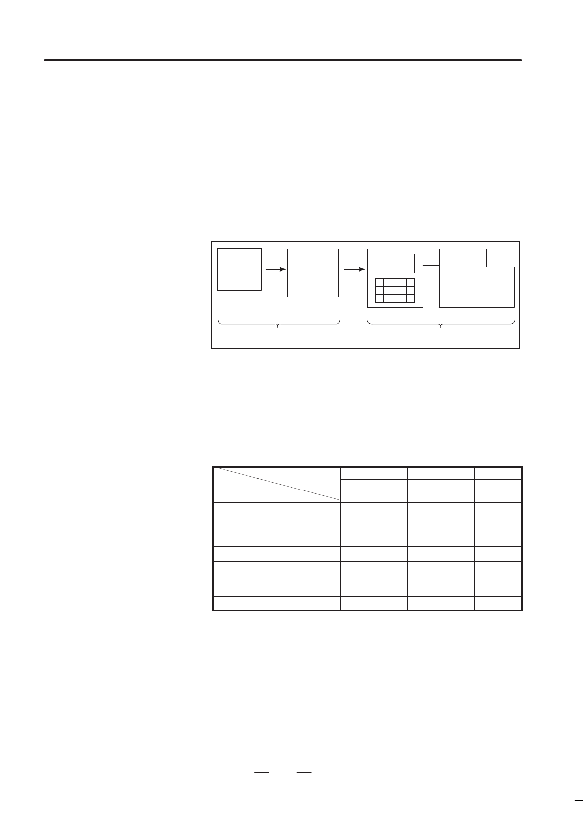
When machining the part using the CNC machine tool, first prepare the
program, then operate the CNC machine by using the program.
1) First, prepare the program from a part drawing to operate the CNC
machine tool.
How to prepare the program is described in the Chapter II.
PROGRAMMING.
2) The program is to be read into the CNC system. Then, mount the
workpieces and tools on the machine, and operate the tools according
to the programming. Finally, execute the machining actually.
How to operate the CNC system is described in the Chapter III.
OPERATION.
Part
drawing
CHAPTER II PROGRAMMING CHAPTER III OPERATION
Part
programming
CNC
MACHINE TOOL
Before the actual programming, make the machining plan for how to
machine the part.
Machining plan
1. Determination of workpieces machining range
2. Method of mounting workpieces on the machine tool
3. Machining sequence in every cutting process
4. Cutting tools and cutting conditions
Decide the cutting method in every cutting process.
in
Cutting procedure
1. Cutting method
: Rough
Semi
Finish
2. Cutting tools
3. Cutting conditions
: Feedrate
Cutting depth
4. Tool path
pr
1 2 3
End face
cutting
Outer diameter
cutting
Grooving
5
Page 17

1. GENERAL
GENERAL
B–62444E/03
Grooving
Outer
diameter
cutting
Workpiece
End
face
cutting
Prepare the program of the tool path and cutting condition
according to the workpiece figure, for each cutting.
6
Page 18

B–62444E/03
GENERAL
1. GENERAL
1.2
NOTES ON READING THIS MANUAL
1) The function of an CNC machine tool system depends not only on the
CNC, but on the combination of the machine tool, its magnetic
cabinet, the servo system, the CNC, the operator’s panels, etc. It is too
difficult to describe the function, programming, and operation relating
to all combinations. This manual generally describes these from the
stand–point of the CNC. So, for details on a particular CNC machine
tool, refer to the manual issued by the machine tool builder, which
should take precedence over this manual.
2) Headings are placed in the left margin so that the reader can easily
access necessary information. When locating the necessary
information, the reader can save time by searching though these
headings.
Machining programs, parameters, variables, etc. are
stored in the CNC unit internal non–volatile memory . In
general, these contents are not lost by the switching
ON/OFF of the power. However, it is possible that a
state can occur where precious data stored in the
non–volatile memory has to be deleted, because of
deletions from a maloperation, or by a failure
restoration. In order to restore rapidly when this kind of
mishap occurs, it is recommended that you create a
copy of the various kinds of data beforehand.
This manual describes as many reasonable variations
in equipment usage as possible. It cannot address
every combination of features, options and commands
that should not be attempted.
If a particular combination of operations is not
described, it should not be attempted.
7
Page 19

II. PROGRAMMING
Page 20

B–62444E/03
1
PROGRAMMING
1. GENERAL
11
Page 21
1. GENERAL
PROGRRAMING
B–62444E/03
1.1
TOOL MOVEMENT
ALONG WORKPIECE
PARTS FIGURE–
INTERPOLATION
Explanations
Tool movement along a
straight line
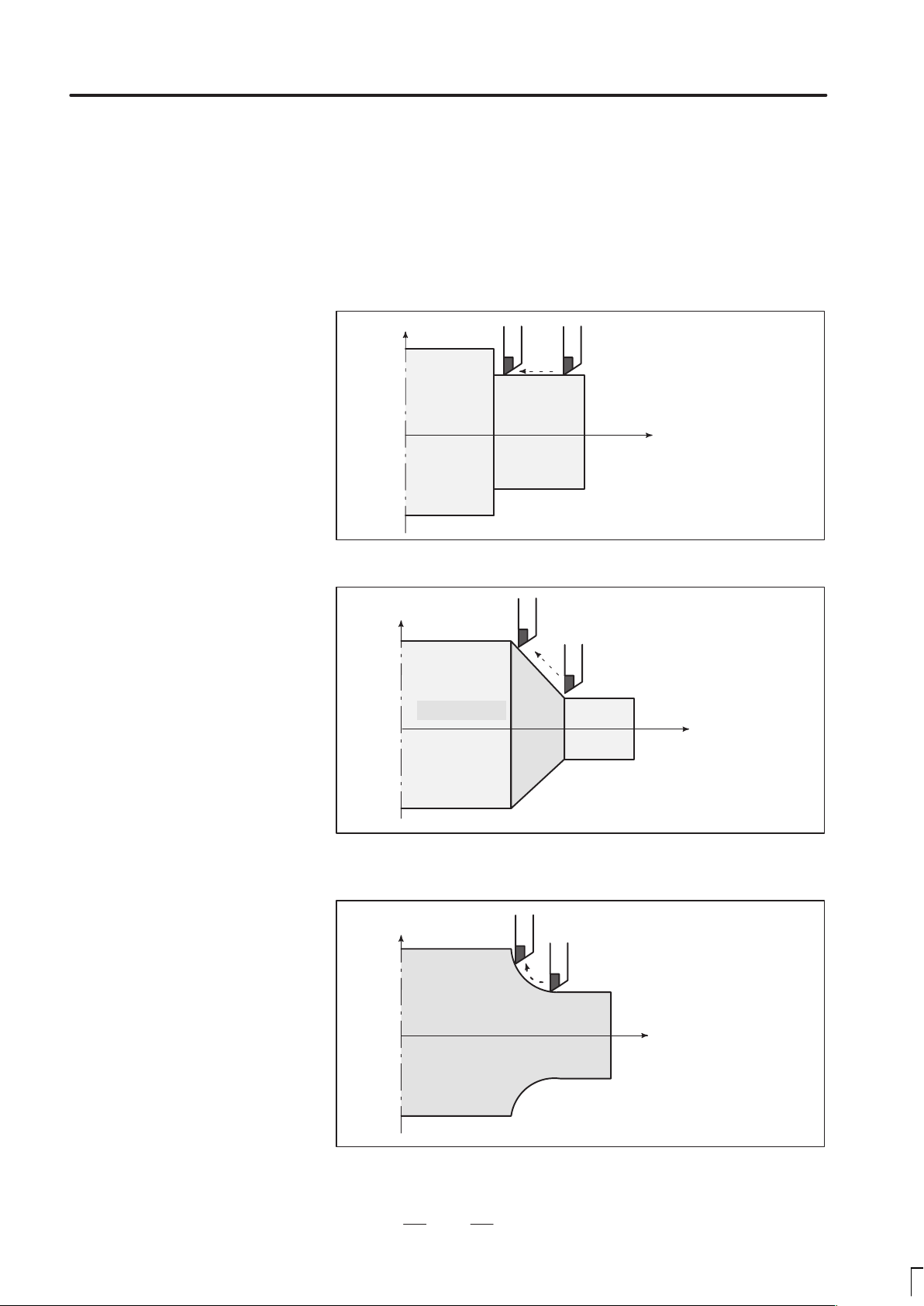
The tool moves along straight lines and arcs constituting the workpiece
parts figure (See II–4).
X
Tool
Workpiece
Fig.1.1 (a) Tool movement along the straight line which is parallel to Z–axis
Program
G01 Z...;
Z
Tool movement along an
arc
X
Tool
Workpiece
Fig.1.1 (b) Tool movement along the taper line
X
Workpiece
Tool
Program
G01 X ... Z... ;
Z
Program
G02X ... Z ... R ... ;
or
G03X ... Z ... R ... ;
Z
Fig. 1.1 (c) Tool movement along an arc
12
Page 22
B–62444E/03
PROGRAMMING
1. GENERAL
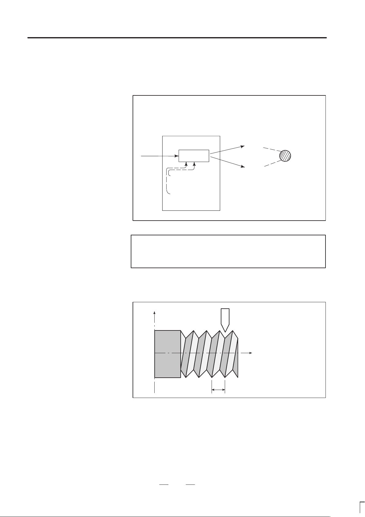
The term interpolation refers to an operation in which the tool moves
along a straight line or arc in the way described above.
Symbols of the programmed commands G01, G02, ... are called the
preparatory function and specify the type of interpolation conducted in
the control unit.
(a) Movement along straight line
G01 Z__;
X––Z––––;
Control unit
Interpolation
a) Movement
along straight
line
b) Movement
along arc
Fig. 1.1 (d) Interpolation function
(b) Movement along arc
G03X––Z––;
X axis
Y axis
Tool
movement
Notes
Some machines move tables instead of tools but this
manual assumes that tools are moved against workpieces.
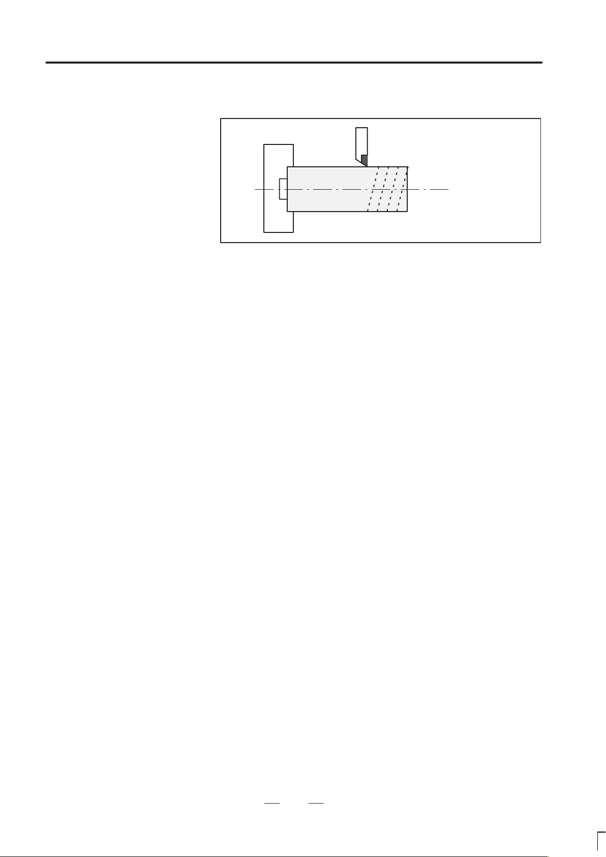
Thread cutting
Threads can be cut by moving the tool in synchronization with spindle
rotation. In a program, specify the thread cutting function by G32.
X
Workpiece
Fig. 1.1 (e) Straight thread cutting
Tool
Z
F
Program
G32Z––F––;
13
Page 23
1. GENERAL
PROGRRAMING
B–62444E/03
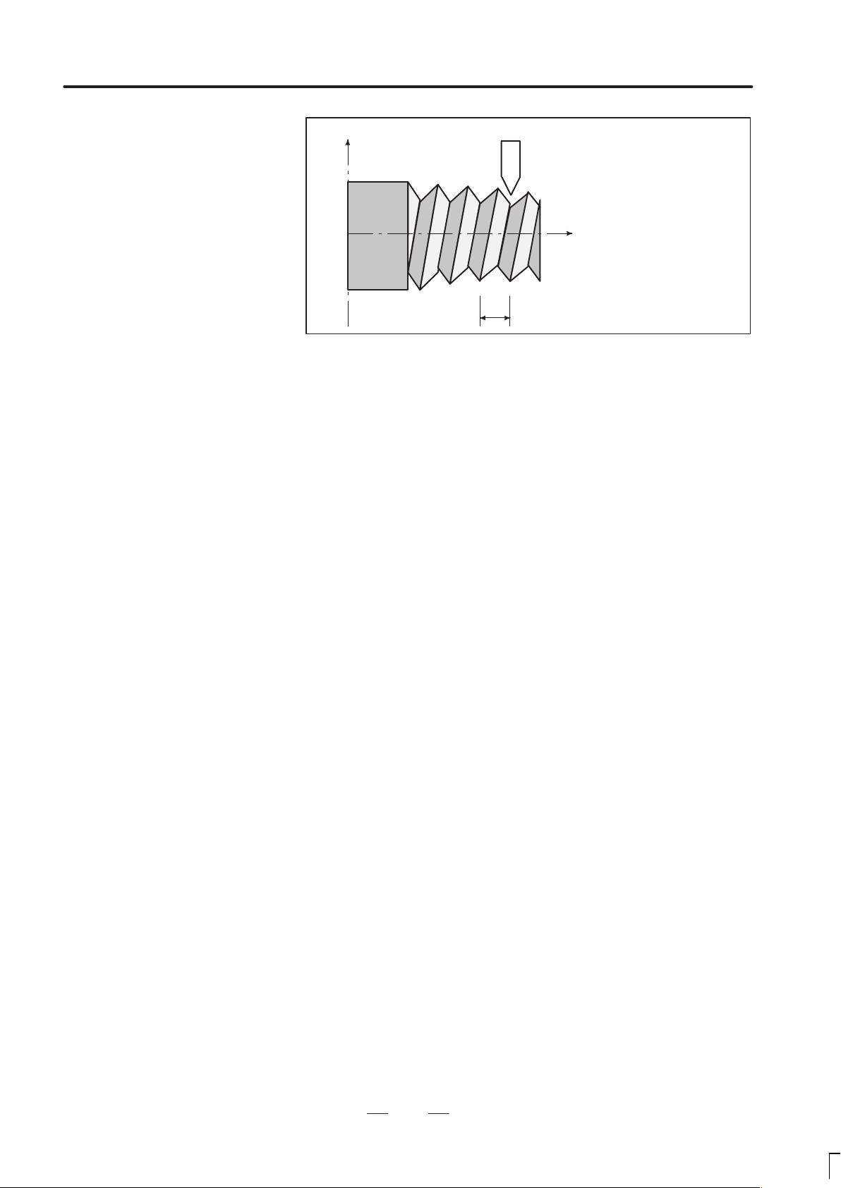
X
Workpiece
Tool
Program
G32X––Z––F––;
Z
F
Fig. 1.1 (f) Taper thread cutting
14
Page 24
B–62444E/03
PROGRAMMING
1. GENERAL
1.2
FEED–
FEED FUNCTION
Movement of the tool at a specified speed for cutting a workpiece is called
the feed.
Chuck
Workpiece
Fig. 1.2 (a) Feed function
Tool
Feedrates can be specified by using actual numerics.
For example, the following command can be used to feed the tool 2 mm
while the workpiece makes one turn :
F2.0
The function of deciding the feed rate is called the feed function (See
II–5).
15
Page 25
1. GENERAL
1.3
PART DRAWING AND TOOL MOVEMENT
PROGRRAMING
B–62444E/03
1.3.1
Reference Position
(Machine–Specific
Position)
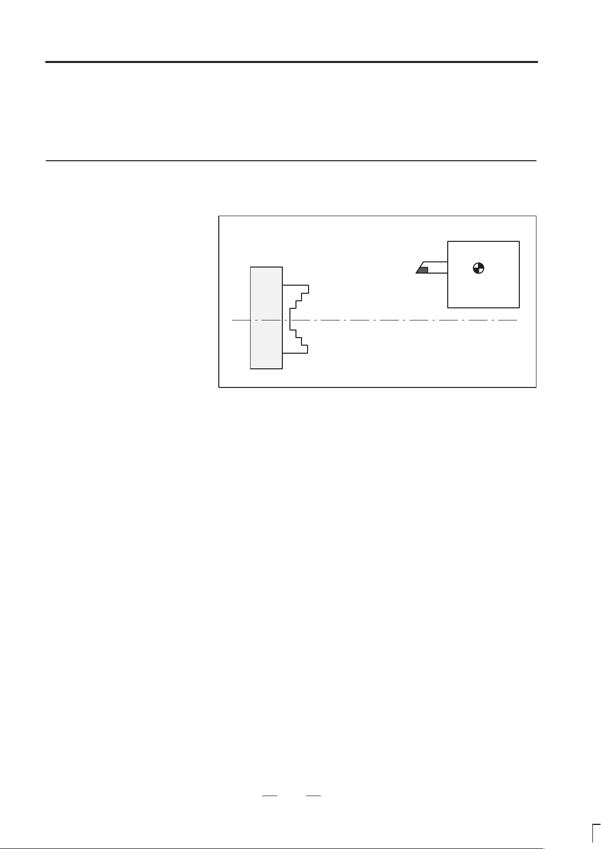
Explanations
A CNC machine tool is provided with a fixed position. Normally, tool
change and programming of absolute zero point as described later are
performed at this position. This position is called the reference position.
Tool post
Chuck
Fig. 1.3.1 (a) Reference position
The tool can be moved to the reference position in two ways:
1. Manual reference position return (See III–3.1)
Reference position return is performed by manual button operation.
Reference
position
2. Automatic reference position return (See II–6)
In general, manual reference position return is performed first after
the power is turned on. In order to move the tool to the reference
position for tool change thereafter, the function of automatic
reference position return is used.
16
Page 26
B–62444E/03
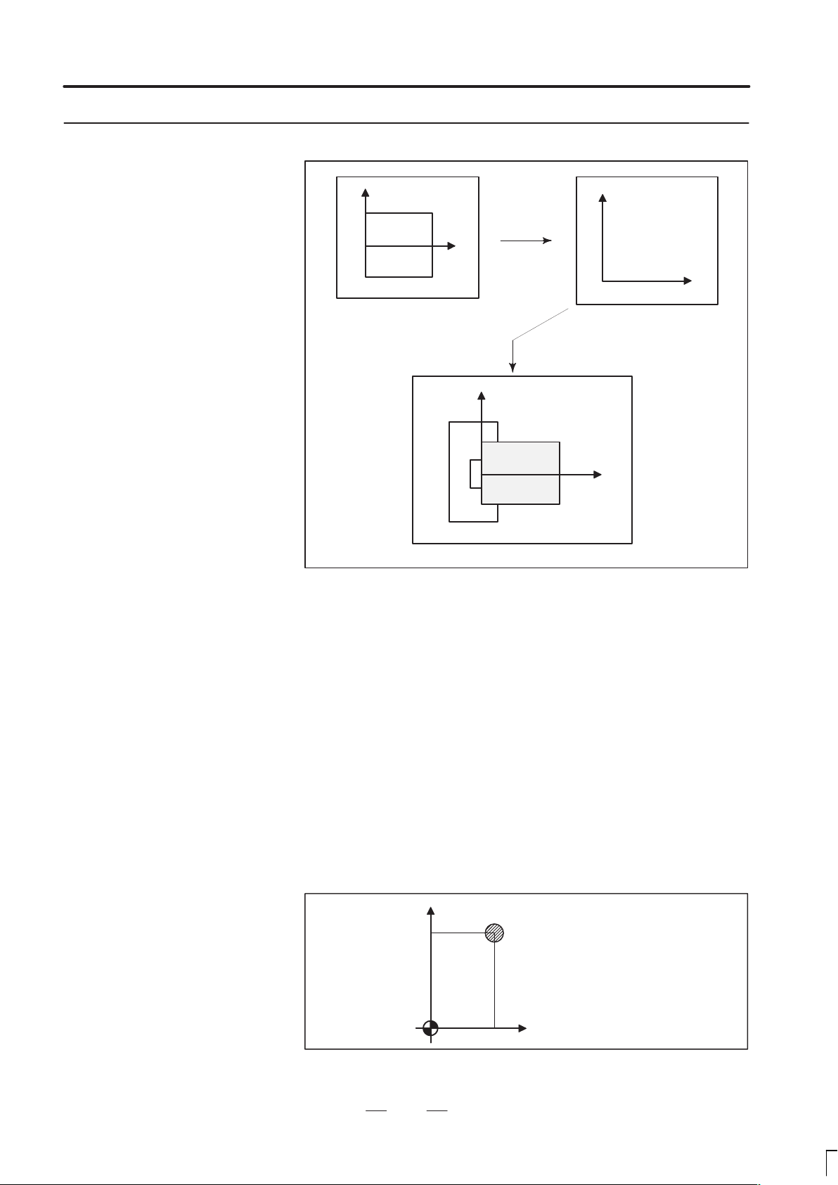
1.3.2
Coordinate System on
Part Drawing and
Coordinate System
Specified by CNC –
Coordinate System
PROGRAMMING
X
Part drawing
1. GENERAL
X
Program
Z
Z
Coordinate system
CNC
Command
X
Workpiece
Explanations
Coordinate system
Z
Machine tool
Fig. 1.3.2 (a) Coordinate system
The following two coordinate systems are specified at different locations:
(See II–8)
1. Coordinate system on part drawing
The coordinate system is written on the part drawing. As the program
data, the coordinate values on this coordinate system are used.
2. Coordinate system specified by the CNC
The coordinate system is prepared on the actual machine tool. This
can be achieved by programming the distance from the current
position of the tool to the zero point of the coordinate system to be
set.
230
300
Program
zero point
Fig. 1.3.2 (b) Coordinate system specified by the CNC
Present tool position
Distance to the zero point of a coordinate system to be set
17
Page 27
1. GENERAL
PROGRRAMING
B–62444E/03
The tool moves on the coordinate system specified by the CNC in
accordance with the command program generated with respect to the
coordinate system on the part drawing, and cuts a workpiece into a shape
on the drawing.
Therefore, in order to correctly cut the workpiece as specified on the
drawing, the two coordinate systems must be set at the same position.
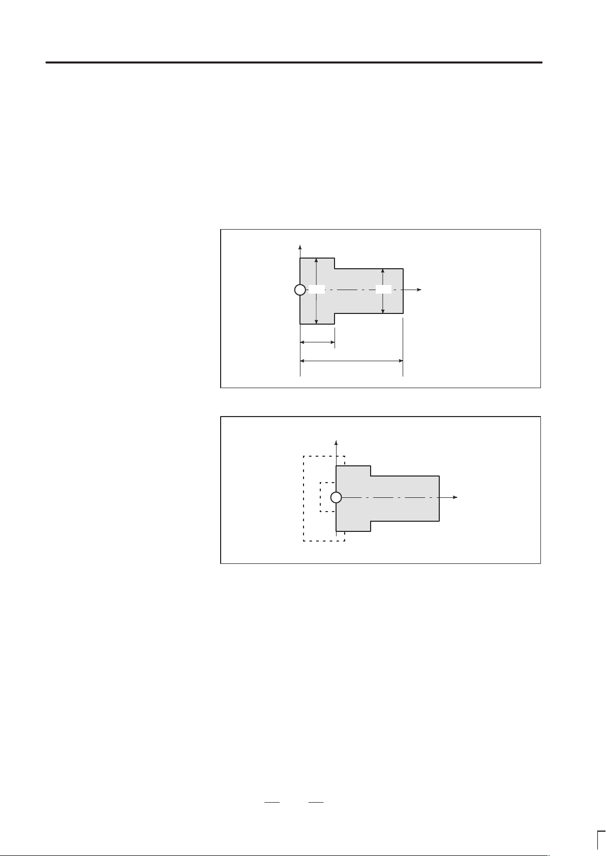
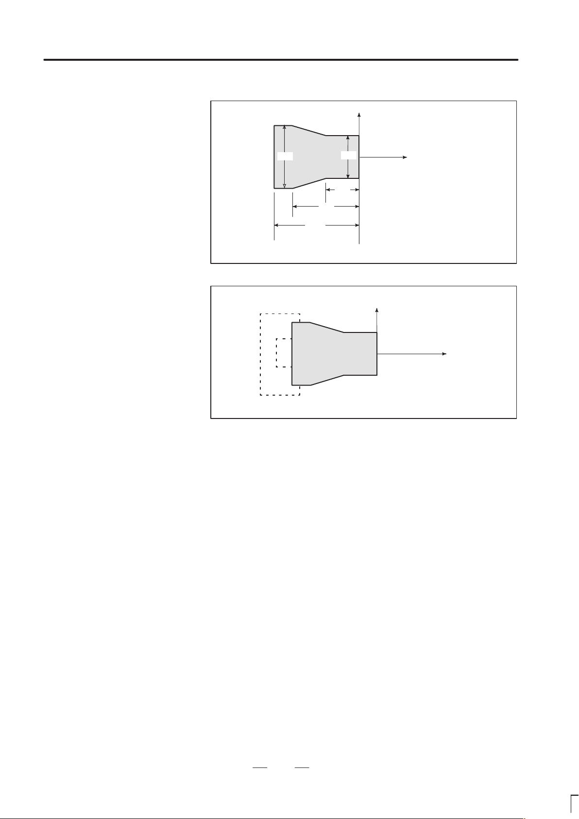
Methods of setting the
two coordinate systems
in the same position
The following method is usually used to define two coordinate systems
at the same location.
1. When coordinate zero point is set at chuck face
X
Workpiece
60
40
150
Fig. 1.3.2 (c)Coordinates and dimensions on part drawing
X
40
Z
Workpiece
Z
Fig. 1.3.2 (d)Coordinate system on lathe as specified by CNC
(made to coincide with the coordinate system on part drawing)
18
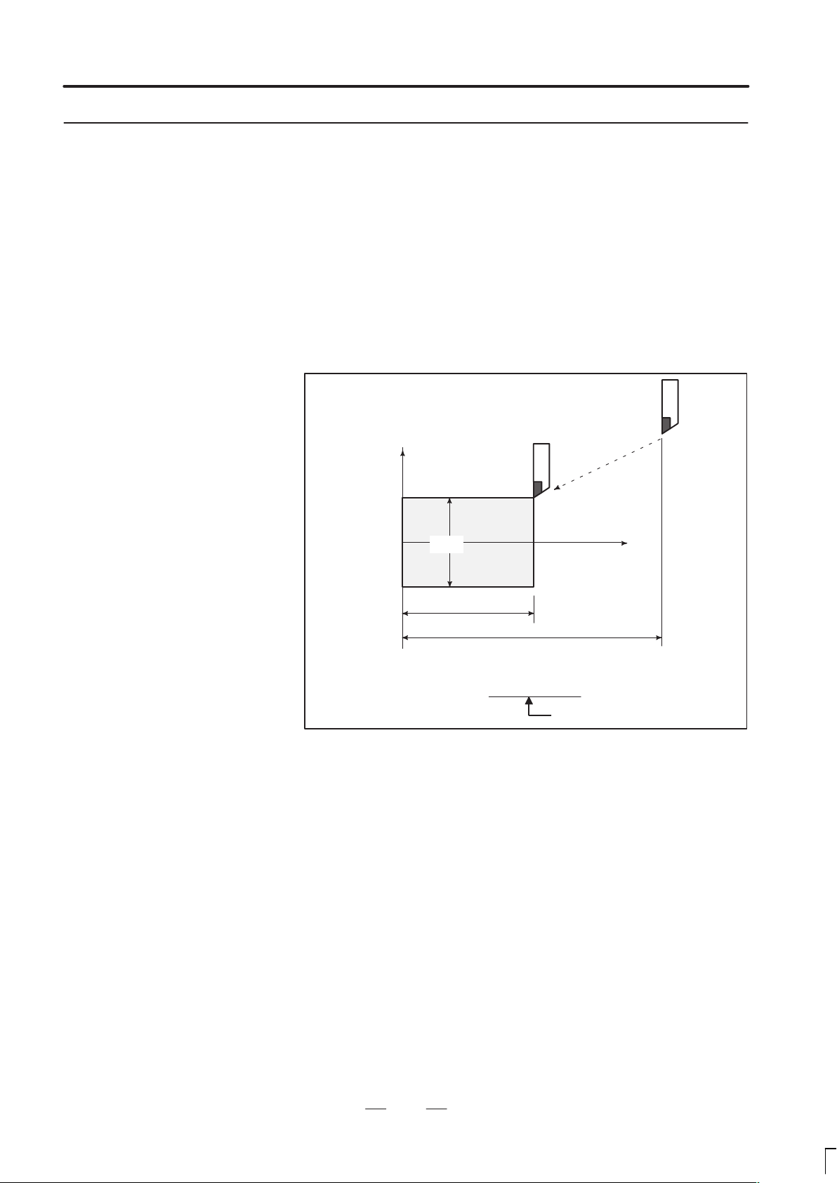
Page 28
B–62444E/03
PROGRAMMING
2. When coordinate zero point is set at work end face.
X
1. GENERAL
Workpiece
60
100
Fig. 1.3.2 (e) Coordinates and dimensions on part drawing
Workpiece
Fig. 1.3.2 (f) Coordinate system on lathe as specified by CNC
(made to coincide with the coordinate system on part drawing)
30
Z
30
80
X
Z
19
Page 29
1. GENERAL
1.3.3
How to Indicate
Command Dimensions
for Moving the Tool –
Absolute, Incremental
Commands
PROGRRAMING
B–62444E/03
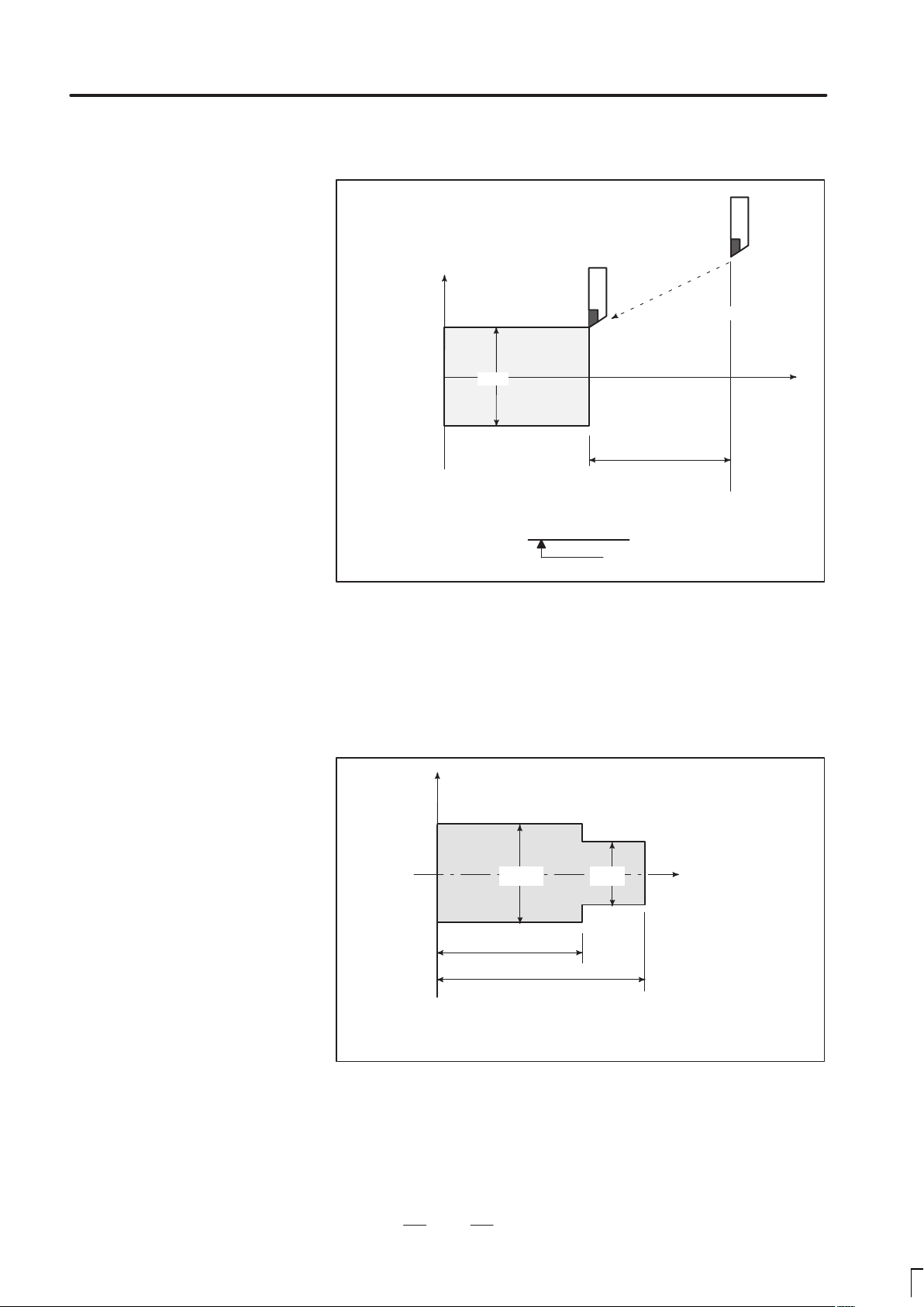
Explanations
Absolute command
Methods of command for moving the tool can be indicated by absolute
or incremental designation (See II–9.1).
The tool moves to a point at ”the distance from zero point of the
coordinate system” that is to the position of the coordinate values.
Tool
X
Workpiece
φ30
70
Command specifying movement from point A to point B
G90X30.0Z70.0;
B
110
A
Z
Fig. 1.3.3 (a) Absolute command
20
Coordinates of point B
Page 30
B–62444E/03
PROGRAMMING
1. GENERAL
Incremental command
Specify the distance from the previous tool position to the next tool
position.
Tool
A
X
φ60
B
Z
φ30
40
Command specifying movement from point A to point B
U–30.0W–40.0
Distance and direction for
movement along each axis
Diameter programming /
radius programming
Fig. 1.3.3 (b) Incremental command
Dimensions of the X axis can be set in diameter or in radius. Diameter
programming or radius programming is employed independently in each
machine.
1. Diameter programming
In diameter programming, specify the diameter value indicated on the
drawing as the value of the X axis.
X
B
Workpiece
φ40
60
80
Coordinate values of points A and B
A(30.0, 80.0), B(40.0, 60.0)
φ30
A
Z
Fig. 1.3.3 (c) Diameter programming
21
Page 31

1. GENERAL
PROGRRAMING
B–62444E/03
2. Radius programming
In radius programming, specify the distance from the center of the
workpiece, i.e. the radius value as the value of the X axis.
X
B
20
Workpiece
60
80
Coordinate values of points A and B
A(15.0, 80.0), B(20.0, 60.0)
Fig. 1.3.3 (d) Radius programming
A
15
Z
22
Page 32

B–62444E/03
PROGRAMMING
1. GENERAL
1.4
CUTTING SPEED –
SPINDLE SPEED
FUNCTION
Examples
The speed of the tool with respect to the workpiece when the workpiece
is cut is called the cutting speed.
As for the CNC, the cutting speed can be specified by the spindle speed
in rpm unit.
Tool
Workpiece
Fig. 1.4 (a) Cutting speed
V: Cutting speed
v m/min
φ
N rpm
<When a workpiece 200 mm in diameter should be machined at
a cutting speed of 300 m/min. >
The spindle speed is approximately 478 rpm, which is obtained from
N=1000v/πD. Hence the following command is required:
S478 ;
Commands related to the spindle speed are called the spindle speed
function (See II–10).
The cutting speed v (m/min) can also be specified directly by the speed
value. Even when the workpiece diameter is changed, the CNC changes
the spindle speed so that the cutting speed remains constant.
This function is called the constant surface speed control function
(See II–10.2).
23
Page 33

1. GENERAL
PROGRRAMING
B–62444E/03
1.5
SELECTION OF TOOL
USED FOR VARIOUS
MACHINING – TOOL
FUNCTION
Examples
When drilling, tapping, boring, milling or the like, is performed, it is
necessary to select a suitable tool. When a number is assigned to each tool
and the number is specified in the program, the corresponding tool is
selected.
Tool number
01
06
02
03
Fig. 1.5 (a) Tool used for various machining
05
04
Tool post
<When No.01 is assigned to a roughing tool>
When the tool is stored at location 01 of the tool post, the tool can be
selected by specifying T0101.
This is called the tool function (See II–11).
24
Page 34

B–62444E/03
PROGRAMMING
1. GENERAL
1.6
COMMAND FOR
MACHINE
OPERATIONS –
MISCELLANEOUS
FUNCTION
When machining is actually started, it is necessary to rotate the spindle,
and feed coolant. For this purpose, on–off operations of spindle motor and
coolant valve should be controlled (See II–12).
Coolant on/off
Chuck open/close
Workpiece
Fig. 1.6 (a) Command for machine operations
CW spindle rotation
The function of specifying the on–off operations of the components of the
machine is called the miscellaneous function. In general, the function is
specified by an M code.
For example, when M03 is specified, the spindle is rotated clockwise at
the specified spindle speed.
25
Page 35

1. GENERAL
PROGRRAMING
B–62444E/03
1.7
PROGRAM CONFIGURATION
A group of commands given to the CNC for operating the machine is
called the program. By specifying the commands, the tool is moved along
a straight line or an arc, or the spindle motor is turned on and off.
In the program, specify the commands in the sequence of actual tool
movements.
Block
Block
Tool movement sequence
Block
Program
Block
⋅
⋅
⋅
⋅
Block
Fig. 1.7 (a) Program configuration
A group of commands at each step of the sequence is called the block.
The program consists of a group of blocks for a series of machining. The
number for discriminating each block is called the sequence number, and
the number for discriminating each program is called the program
number (See II–13).
26
Page 36

B–62444E/03
PROGRAMMING
1. GENERAL
Explanations
D Block
D Program
The block and the program have the following configurations.
1 block
N fffff G ff Xff.f Zfff.f M ff S ff T ff ;
Sequence
number
Preparatory
function
Dimension word Miscel-
laneous
function
Fig. 1.7 (b) Block configuration
Spindle
function
Tool
function
End of
block
A block begins with a sequence number that identifies that block and ends
with an end–of–block code.
This manual indicates the end–of–block code by ; (LF in the ISO code and
CR in the EIA code).
;
Offff;
⋅
⋅
⋅
M30 ;
Fig. 1.7 (c) Program configuration
Program number
Block
Block
Block
⋅
⋅
⋅
End of program
Normally , a program number is specified after the end–of–block (;) code
at the beginning of the program, and a program end code (M02 or M30)
is specified at the end of the program.
27
Page 37

1. GENERAL
PROGRRAMING
B–62444E/03
Main program and
subprogram
When machining of the same pattern appears at many portions of a
program, a program for the pattern is created. This is called the
subprogram. On the other hand, the original program is called the main
program. When a subprogram execution command appears during
execution of the main program, commands of the subprogram are
executed. When execution of the subprogram is finished, the sequence
returns to the main program.
Main program
⋅
⋅
M98P1001
⋅
⋅
⋅
M98P1002
⋅
⋅
⋅
M98P1001
⋅
⋅
Subprogram #1
O1001
M99
Subprogram #2
O1002
Program for
hole #1
Program for
hole #2
⋅
M99
28
Page 38

B–62444E/03
1.8
TOOL FIGURE AND TOOL MOTION BY PROGRAM
Explanations
PROGRAMMING
1. GENERAL
Machining using the end
of cutter – Tool length
compensation function
(See II–15.1)
Usually, several tools are used for machining one workpiece. The tools
have different tool length. It is very troublesome to change the program
in accordance with the tools.
Therefore, the length of each tool used should be measured in advance.
By setting the difference between the length of the standard tool and the
length of each tool in the CNC (data display and setting : see III–11),
machining can be performed without altering the program even when the
tool is changed. This function is called tool length compensation.
Workpiece
Standard
tool
Rough
cutting
tool
Fig. 1.8 (a) Tool offset
Finishing
tool
Grooving
tool
Thread
cutting
tool
29
Page 39

1. GENERAL
PROGRRAMING
B–62444E/03
1.9
TOOL MOVEMENT
RANGE – STROKE
Limit switches are installed at the ends of each axis on the machine to
prevent tools from moving beyond the ends. The range in which tools can
move is called the stroke. Besides the stroke limits, data in memory can
be used to define an area which tools cannot enter.
Table
Motor
Limit switch
Machine zero point
Specify these distances.
Tools cannot enter this area. The area is specified by data in memory or
a program.
Besides strokes defined with limit switches, the operator can define an
area which the tool cannot enter using a program or data in memory (see
Section III–11). This function is called stroke check.
30
Page 40

B–62444E/03
2
PROGRAMMING
CONTROLLED AXES
2. CONTORLED AXES
31
Page 41

2. CONTROLED AXES
2.1
CONTROLLED AXES
Series 16
Series 160
PROGRAMMING
Item
Number of basic
controlled axes
Controlled axis expansion
(total)
Number of basic simultaneously controlled axes
Simultaneously controlled
axis expansion (total)
16–TB
160–TB
2 axes 2 axes for each tool post
Max. 8 axes
(Included in Cs axis)
2 axes 2 axes for each tool post
Max. 6 axes Max. 4 axes for each tool
16–TB, 160–TB
(two–path control)
(4 axes in total)
Max. 6 axes for each tool
post +Cs axis (Note)
(4 axes in total)
post
B–62444E/03
Note
A two–path control system with a 9–inch CRT has up to eight controlled
axes.
Series 18
Series 180
Note
The number of simultaneously controllable axes for manual
operation (jog feed, incremental feed, or manual handle
feed) is 1 or 3 (1 when bit 0 (JAX) of parameter 1002 is set
to 0 and 3 when it is set to 1).
Item
Number of basic
controlled axes
Controlled axis expansion
(total)
Number of basic simultaneously controlled axes
Simultaneously controlled
axis expansion (total)
18–TB
180–TB
2 axes 2 axes for each tool post
Max. 6 axes
(Included in Cs axis)
2 axes 2 axes for each tool post
Max. 4 axes Max. 4 axes for each tool
Note
A two–path control system with a 9–inch CRT has up to eight controlled
axes.
18–TB, 180–TB
(two–path control)
(4 axes in total)
Max. 4 axes for each tool
post +Cs axis (Note)
(4 axes in total)
post
Note
The number of simultaneously controllable axes for manual
operation (jog feed, incremental feed, or manual handle
feed) is 1 or 3 (1 when bit 0 (JAX) of parameter 1002 is set
to 0 and 3 when it is set to 1).
32
Page 42

B–62444E/03
PROGRAMMING
2. CONTORLED AXES
2.2
NAMES OF AXES
Limitations
Default axis name
Duplicate axis name
Nine letters, A, B, C, U, V, W, X, Y, and Z, can be used as axis names.
Each axis name is determined according to parameter No. 1020. If the
parameter specifies 0 or anything other than the nine letters, the axis
name defaults to a number from 1 to 8.
With two–path control, the names of two basic axes for one tool post
are always X and Z; the names of additional axes can be optionally
selected from A, B, C, U, V, W, and Y by using parameter No. 1020.
For one tool post, the same axis name cannot be assigned to multiple
axes, but the same axis name can be used
with the other tool post.
When a default axis name (1 to 8) is used, the system cannot operate in
MEM or MDI mode.
If the parameter specifies an axis name more than once, only the first
axis to be assigned that axis name becomes operable.
Notes
1 When G code system A is used, the letters U, V, and W
cannot be used as an axis name (hence, the maximum of
six controlled axes), because these letters are used as
incremental commands for X, Y, and Z. To use the letters
U, V, and W as axis names, the G code system must be
B or C. Likewise, letter H is used as an incremental
command for C, thus incremental commands cannot be
used if A or B is used as an axis name.
2 With two–path control, when information (such as the
current position) about each axis is displayed on the CRT
screen, an axis name may be followed by a subscript to
indicate a tool post number (e.g.,X1 and X2). This is axis
name to help the user to easily understand which tool
post an axis belongs to. When writing a program, the
user must specify X, Y, Z, U, V, W, A, B, and C without
attaching a subscript.
3 In G76 (multiple–thread cutting), the A address in a block
specifies the tool nose angle instead of a command for
axis A.
If C or A is used as an axis name, C or A cannot be used
as an angle command for a straight line in chamfering or
direct drawing dimension programming. Therefore, C and
A should be used according to bit 4 (CCR) of parameter
No. 3405.
33
Page 43

2. CONTROLED AXES
i
t
a
i
t
i
t
ce
i
t
i
t
a
i
t
i
t
ce
i
t
PROGRAMMING
B–62444E/03
2.3
INCREMENT SYSTEM
The increment system consists of the least input increment (for input )
and least command increment (for output). The least input increment
is the least increment for programming the travel distance. The least
command increment is the least increment for moving the tool on the
machine. Both increments are represented in mm, inches, or degrees.
The increment system is classified into IS–B and IS–C (Tables 2.3(a)
and 2.3(b)). Select IS–B or IS–C using bit 1 (ISC) of parameter 1004.
When selecting IS–C, the option for the 1/10 increment system is
necessary.
T able 2.3 (a) Increment system IS–B
Least input increment Least command increment
Metric
system
machine
Inch
machine
system
mm
npu
inch
npu
mm
npu
inch
npu
0.001mm(Diameter) 0.0005mm
0.001mm(Radius) 0.001mm
0.001deg 0.001deg
0.0001inch(Diameter) 0.0005mm
0.0001inch(Radius) 0.001mm
0.001deg 0.001deg
0.001mm(Diameter) 0.00005inch
0.001mm(Radius) 0.0001inch
0.001deg 0.001deg
0.0001inch(Diameter) 0.00005inch
0.0001inch(Radius) 0.0001inch
0.001deg 0.001deg
Metric
system
machine
Inch
machine
system
T able 2.3 (b) Increment system IS–C
Least input increment Least command increment
mm
npu
inch
npu
mm
npu
inch
npu
0.0001mm(Diameter) 0.00005mm
0.0001mm(Radius) 0.0001mm
0.0001deg 0.0001deg
0.00001inch(Diameter) 0.00005mm
0.00001inch(Radius) 0.0001mm
0.0001deg 0.0001deg
0.0001mm(Diameter) 0.000005inch
0.0001mm(Radius) 0.00001inch
0.0001deg 0.0001deg
0.00001inch(Diameter) 0.000005inch
0.00001inch(Radius) 0.00001inch
0.0001deg 0.0001deg
34
Page 44

B–62444E/03
IS–B
IS–C
PROGRAMMING
2. CONTORLED AXES
2.4
MAXIMUM STROKES
The maximum stroke controlled by this CNC is shown in the table
below:
Maximum stroke=Least command increment99999999
T able 2.4 (a) Maximum strokes
Increment system
Metric machine
system
–
Inch machine
system
Metric machine
system
–
Inch machine
system
Maximum strokes
99999.999 mm
99999.999 deg
9999.9999 inch
99999.999 deg
9999.9999 mm
9999.9999 deg
999.99999 inch
9999.9999 deg
Notes
1. The unit in the table is a diameter value with diameter
programming and a radius value in radius programming.
2. A command exceeding the maximum stroke cannot be
specified.
3. The actual stroke depends on the machine tool.
35
Page 45

3.PREP ARATORY FUNCTION
(G FUNCTION)
PREPARATORY FUNCTION (G FUNCTION )
3
PROGRAMMING
A number following address G determines the meaning of the command
for the concerned block.
G codes are divided into the following two types.
Type Meaning
One–shot G code The G code is effective only in the block in which it is
specified
Modal G code The G code is effective until another G code of the
same group is specified.
(Example)
G01 and G00 are modal G codes.
B–62444E/03
G01X ;
Z;
X;
G00Z ;
There are three G code systems : A,B, and C (Table 3). Select a G code
system using bits 6 (GSB) and 7 (GSC) of parameter 3401. Generally , this
manual describes the use of G code system A, except when the described
item can use only G code system B or C. ln such cases, the use of G code
system B or C is described.
G01 is effective in this range
36
Page 46

B–62444E/03
PROGRAMMING
3. PREP ARATORY FUNCTION
(G FUNCTION)
Explanations
1. If the CNC enters the clear state (see bit 6 (CLR) of parameter 3402)
when the power is turned on or the CNC is reset, the modal G codes
change as follows.
(1)G codes marked with
in Table 3 are enabled.
(2)When the system is cleared due to power-on or reset,
whichever specified, either G20 or G21, remains effective.
(3)Bit 7 of parameter No. 3402 can be used to specify whether
G22 or G23 is selected upon power-on. Resetting the CNC
to the clear state does not affect the selection of G22 or
G23.
(4)Setting bit 0 (G01) of parameter 3402 determines which
code, either G00 or G01, is effective.
(5)Setting bit 3 (G91) of parameter 3402 determines which
code, either G90 or G91, is effective.
2. G codes of group 00 except G10 and G11 are single-shot G
codes.
3. P/S larm (No.010) is displayed when a G code not listed in the
G code list is specified or a G code without a corresponding
option is specified.
4. G codes of different groups can be specified in the same block.
If G codes of the same group are specified in the same block,
the G code specified last is valid.
5. If a G code of group 01 is specified in a canned cycle, the
canned cycle is canceled in the same way as when a G80
command is specified. G codes of group 01 are not affected by
G codes for specifying a canned cycle.
6. When G code system A is used for a canned cycle, only the
initial level is provided at the return point.
7. G codes are displayed for each group number.
37
Page 47

3.PREP ARATORY FUNCTION
Grou
Function
01
06
09
08
01
00
(G FUNCTION)
G code
A B C
G00 G00 G00
G01 G01 G01
G02 G02 G02
G03 G03 G03 Circular interpolation CCW or Helical interpolation CCW
G04 G04 G04 Dwell
G05 G05 G05 High speed cycle cutting
G07.1
(G107)
G10
G10.6 G10.6 G10.6 Tool retract & recover
G11 G11 G11 Programmable data input cancel
G12.1
(G112)
G13.1
(G113)
G17 G17 G17
G18 G18 G18
G19 G19 G19 Y pZp plane selection
G20 G20 G70
G21 G21 G71
G22 G22 G22
G23 G23 G23
G25 G25 G25
G26 G26 G26
G27 G27 G27 Reference position return check
G28 G28 G28 Return to reference position
G30 G30 G30 00 2nd, 3rd and 4th reference position return
G30.1 G30.1 G30.1 Floating reference point return
G31 G31 G31 Skip function
G32 G33 G33
G34 G34 G34
G36 G36 G36 Automatic tool compensation X
G37 G37 G37 00 Automatic tool compensation Z
G39 G39 G39 Corner circular interpolation
G40 G40 G40
G41 G41 G41
G42 G42 G42 Tool nose radius compensation right
G50 G92 G92
G50.3 G92.1 G92.1
G07.1
(G107)
G10 G10
G12.1
(G112)
G13.1
(G113)
G07.1
(G107)
G12.1
(G112)
G13.1
(G113)
PROGRAMMING
Table 3 G code list (1/3)
p
00
21
16
07
B–62444E/03
Positioning (Rapid traverse)
Linear interpolation (Cutting feed)
Circular interpolation CW or Helical interpolation CW
Cylindrical interpolation
Programmable data input
Polar coordinate interpolation mode
Polar coordinate interpolation cancel mode
XpY p plane selection
ZpXp plane selection
Input in inch
Input in mm
Stored stroke check function on
Stored stroke check function off
Spindle speed fluctuation detection off
Spindle speed fluctuation detection on
Thread cutting
V ariable–lead thread cutting
Tool nose radius compensation cancel
Tool nose radius compensation left
Coordinate system setting or max. spindle speed setting
Workpiece coordinate system preset
38
Page 48

B–62444E/03
Grou
Function
20
00
14
12
04
00
10
02
G50.2
(G250)
G51.2
(G251)
G52 G52 G52
G53 G53 G53
G54 G54 G54
G55 G55 G55
G56 G56 G56
G57 G57 G57
G58 G58 G58 Workpiece coordinate system 5 selection
G59 G59 G59 Workpiece coordinate system 6 selection
G65 G65 G65 00 Macro calling
G66 G66 G66
G67 G67 G67
G68 G68 G68
G69 G69 G69
G70 G70 G72 Finishing cycle
G71 G71 G73
G72 G72 G74
G73 G73 G75 Pattern repeating
G74 G74 G76 End face peck drilling
G75 G75 G77 Outer diameter/internal diameter drilling
G76 G76 G78 Multiple threading cycle
G71 G71 G72 Traverse grinding cycle (for grinding machine)
G72 G72 G73
G73 G73 G74 Oscilation grinding cycle (for grinding machine)
G74 G74 G75
G80 G80 G80
G83 G83 G83 Cycle for face drilling
G84 G84 G84
G86 G86 G86
G87 G87 G87 Cycle for side drilling
G88 G88 G88 Cycle for side tapping
G89 G89 G89 Cycle for side boring
G90 G77 G20 Outer diameter/internal diameter cutting cycle
G92 G78 G21 01 Thread cutting cycle
G94 G79 G24 Endface turning cycle
G96 G96 G96
G97 G97 G97
G code
A B C
G50.2
(G250)
G51.2
(G251)
G50.2
(G250)
G51.2
(G251)
PROGRAMMING
Table 3 G code list (2/3)
p
Polygonal turning cancel
Polygonal turning
Local coordinate system setting
Machine coordinate system setting
Workpiece coordinate system 1 selection
Workpiece coordinate system 2 selection
14
01
Workpiece coordinate system 3 selection
Workpiece coordinate system 4 selection
Macro modal call
Macro modal call cancel
Mirror image for double turrets ON or balance cut mode
Mirror image for double turrets OFF or balance cut mode cancel
Stock removal in turning
Stock removal in facing
Traverse direct constant–dimension grinding cycle
(for grinding machine)
Oscilation direct constant–dimension grinding cycle
(for grinding machine)
Canned cycle for drilling cancel
Cycle for face tapping
Cycle for face boring
Constant surface speed control
Constant surface speed control cancel
3. PREP ARATORY FUNCTION
(G FUNCTION)
39
Page 49

3.PREP ARATORY FUNCTION
Grou
Function
05
03
11
(G FUNCTION)
G code
A B C
G98 G94 G94
G99
G91 G91
G98 G98
G99 G99
G95 G95
G90 G90
PROGRAMMING
Table 3 G code list (3/3)
p
Per minute feed
Per revolution feed
Absolute programming
Incremental programming
Return to initial level (See Explanations 6)
Return to R point level (See Explanations 6)
B–62444E/03
40
Page 50

B–62444E/03
4
PROGRAMMING
INTERPOLATION FUNCTIONS
4. INTERPOLA TION FUNCTIONS
41
Page 51

4. INTERPOLA TION FUNCTIONS
PROGRAMMING
B–62444E/03
4.1
POSITIONING (G00)
Format
Explanations
The G00 command moves a tool to the position in the workpiece system
specified with an absolute or an incremental command at a rapid traverse
rate.
In the absolute command, coordinate value of the end point is
programmed.
In the incremental command the distance the tool moves is programmed.
G00IP_;
IP_: For an absolute command, the coordinates of an end
position, and for an incremental command, the distance
the tool moves.
Either of the following tool paths can be selected according to bit 1 (LRP)
of parameter No. 1401.
Nonlinear interpolation positioning
The tool is positioned with the rapid traverse rate for each axis
separately. The tool path is normally straight.
Linear interpolation positioning
The tool path is the same as in linear interpolation (G01). The tool is
positioned within the shortest possible time at a speed that is not more
than the rapid traverse rate for each axis.
Linear interpolation positioning
End position
Non linear interpolation positioning
Start position
The rapid traverse rate in the G00 command is set to the parameter
No.1420 for each axis independently by the machine tool builder. In the
positioning mode actuated by G00, the tool is accelerated to a
predetermined speed at the start of a block and is decelerated at the end
of a block. Execution proceeds to the next block after confirming the
in–position.
”In–position” means that the feed motor is within the specified range.
This range is determined by the machine tool builder by setting to
parameter No.1826.
42
Page 52

B–62444E/03
Examples
PROGRAMMING
X
56.0
4. INTERPOLA TION FUNCTIONS
30.5
30.0
Restrictions
φ40.0
Z
< Radius programming >
G00X40.0Z56.0 ; (Absolute command)
or
G00U–60.0W–30.5;(Incremental command)
The rapid traverse rate cannot be specified in the address F.
Even if linear interpolation positioning is specified, nonlinear
interpolation positioning is used in the following cases. Therefore, be
careful to ensure that the tool does not foul the workpiece.
G28 specifying positioning between the reference and intermediate
positions.
G53
43
Page 53

4. INTERPOLA TION FUNCTIONS
PROGRAMMING
B–62444E/03
4.2
LINEAR
INTERPOLATION
(G01)
Format
Explanations
Tools can move along a line.
G01 IP_F_;
IP_: For an absolute command, the coordinates of an end
point , and for an incremental command, the distance
the tool moves.
F_: Speed of tool feed (Feedrate)
A tools move along a line to the specified position at the feedrate
specified in F.
The feedrate specified in F is effective until a new value is specified. It
need not be specified for each block.
The feedrate commanded by the F code is measured along the tool path.
If the F code is not commanded, the feedrate is regarded as zero.
For feed–per–minute mode under 2–axis simultaneous control, the
feedrate for a movement along each axis as follows :
Examples
Linear interpolation
G01ααββ
< Diameter programming >
G01X40.0Z20.1F20 ; (Absolute command)
or
G01U20.0W–25.9F20 ; (Incremental command)
Ff ;
Feed rate of α axis direction :
Feed rate of Β axis direction :
Ǹ
L +
2
) 2) 2)
2
X
20.1
F +
F
+
46.0
L
L
f
f
44
φ40.0
End point
Start point
φ20.0
Z
Page 54

B–62444E/03
PROGRAMMING
4. INTERPOLA TION FUNCTIONS
4.3
CIRCULAR
INTERPOLATION
(G02,G03)
Format
The command below will move a tool along a circular arc.
Arc in the XpYp plane
G17
G02
G03
Arc in the ZpXp plane
G18
Arc in the YpZp plane
G19
G02
G03
G02
G03
Xp_Yp_
Xp_Zp_
Yp_Zp_
I_J_
R_
I_K_
R_
J_K_
R_
F_
F_
F_
Table.4.3 Description of the Command Format
Command Description
G17 Specification of arc on XpYp plane
G18 Specification of arc on ZpXp plane
G19 Specification of arc on YpZp plane
G02 Circular Interpolation Clockwise direction (CW)
G03 Circular Interpolation Counterclockwise direction (CCW)
X
p_
Y
p_
Z
p_
I_ Xp axis distance from the start point to the center of an arc with
J_ Yp axis distance from the start point to the center of an arc with
Command values of X axis or its parallel axis
(set by parameter No. 1022)
Command values of Y axis or its parallel axis
(set by parameter No. 1022)
Command values of Z axis or its parallel axis
(set by parameter No. 1022)
sign, radius value
sign, radius value
k_ Zp axis distance from the start point to the center of an arc with
sign, radius value
R_ Arc radius with no sign (always with radius value)
F_ Feedrate along the arc
45
Page 55

4. INTERPOLA TION FUNCTIONS
Explanations
PROGRAMMING
B–62444E/03
Note
The U–, V–, and W–axes (parallel with the basic axis) can
be used with G–codes B and C.
Direction of the circular
interpolation
Distance moved on an
arc
Distance from the start
point to the center of arc
”Clockwise”(G02) and ”counterclockwise”(G03) on the X
(Z
plane or YpZp plane) are defined when the XpYp plane is viewed
pXp
in the positive–to–negative direction of the Z
axis (Yp axis or Xp axis,
p
pYp
plane
respectively) in the Cartesian coordinate system. See the figure below.
Yp
G02
G17
G03
Xp
Xp
G03
G02
Zp
G18
Zp
G02
G19
G03
Yp
The end point of an arc is specified by address Xp, Yp or Zp, and is
expressed as an absolute or incremental value according to G90 or G91.
For the incremental value, the distance of the end point which is viewed
from the start point of the arc is specified.
The arc center is specified by addresses I, J, and K for the Xp, Y p, and Zp
axes, respectively . The numerical value following I, J, or K, however, is
a vector component in which the arc center is seen from the start point,
and is always specified as an incremental value irrespective of G90 and
G91, as shown below.
I, J, and K must be signed according to the direction.
Full–circle programming
End point (x,y)
yx
x
Center
i
Start
point
j
End point (z,x)
z
k
Center
Start
point
End point (y ,z)
z
y
i
Center
j
Start
point
k
I0,J0, and K0 can be omitted.
If the difference between the radius at the start point and that at the
end point exceeds the value in a parameter (No.3410), an P/S alarm
(No.020) occurs.
When X
p, Yp
, and Z
are omitted (the end point is the same as the start
p
point) and the center is specified with I, J, and K, a 360° arc (circle) is
specified.
46
Page 56

B–62444E/03
PROGRAMMING
4. INTERPOLA TION FUNCTIONS
The distance between an arc and the center of a circle that contains the arc
can be specified using the radius, R, of the circle instead of I, J, and K.
In this case, one arc is less than 180
considered. An arc with a sector angle of 180
°, and the other is more than 180° are
°or wider cannot be
specified. If Xp, Yp, and Zp are all omitted, if the end point is located at
the same position as the start point and when R is used, an arc of 0
°is
programmed
G02R ; (The cutter does not move.)
For arc (1) (less than 180°)
G02 W60.0 U10.0 R50.0
For arc (2) (greater than 180°)
An arc with a sector angle of 180°
or wider cannot be specified
within a single block.
F300.0 ;
(2)
Start point
r=50mm
End point
1
r=50mm
X
Feedrate
Restrictions
Z
The feedrate in circular interpolation is equal to the feed rate specified by
the F code, and the feedrate along the arc (the tangential feedrate of the
arc) is controlled to be the specified feedrate.
The error between the specified feedrate and the actual tool feedrate is
±2% or less. However, this feed rate is measured along the arc after the
tool nose radius compensation is applied
If I, J, K, and R addresses are specified simultaneously, the arc specified
by address R takes precedence and the other are ignored.
If an axis not comprising the specified plane is commanded, an alarm is
displayed.
For example, when a ZX plane is specified in G–code B or C, specifying
the X–axis or U–axis (parallel to the X–axis) causes P/S alarm No. 028
to be generated.
If the difference in the radius between the start and end points of the arc
exceeds the value specified in parameter No. 3410, P/S alarm No. 020 is
generated.
If the end point is not on the arc, the tool moves in a straight line along
one of the axes after reaching the end point.
If an arc having a central angle approaching 180 is specified with R, the
calculation of the center coordinates may produce an error. In such a case,
specify the center of the arc with I, J, and K.
47
Page 57

4. INTERPOLA TION FUNCTIONS
Examples
Command of circular
interpolation X, Z
PROGRAMMING
B–62444E/03
G02X_Z_I_K_F_; G03X_Z_I_K_F_;
End point
X–axis
X
Z
Center of arc
K
(Absolute programming)
(Diameter
programming)
Start point
Z–axis Z–axis Z–axis
End point
X–axis X–axis
X
Z
K
(Absolute programming)
X
15.0
R25.0
10.0
φ50.0
30.0
G02X_Z_R_F_;
End point
(Diameter
programming)
Start point
X
Z
(Absolute programming)
(Diameter programming)
G02X50.0Z30.0I25.0F0.3; or
G02U20.0W–020.0I25.0F0.3; or
G02X50.0Z30.0R25.0F0.3 or
G02U20.0W–20.0R25.F0.3;
Z
Center of arc
R
(Diameter
programming)
Start point
50.0
48
Page 58

B–62444E/03
PROGRAMMING
4. INTERPOLA TION FUNCTIONS
4.4
HELICAL
INTERPOLATION
(G02,G03)
Format
Helical interpolation which moved helically is enabled by specifying up
to two other axes which move synchronously with the circular
interpolation by circular commands.
Synchronously with arc of XpYp plane
G17
Synchronously with arc of ZpXp plane
G18
Synchronously with arc of YpZp plane
G19
α,β:Any one axis where circular interpolation is not applied
G02
G03
G02
G03
G02
G03
Up to two other axes can be specified.
XpYp
XpZp
YpZp
IJ
R
IK
R
JK
R
Α(Β)F
αβ)F
ΑΒ)F;
.
Explanations
The command method is to simply or secondary add a move command
axis which is not circular interpolation axes. An F command specifies a
feed rate along a circular arc. Therefore, the feed rate of the linear axis
is as follows:
Length of linear axis
F×
Length of circular arc
Determine the feed rate so the linear axis feed rate does not exceed any
of the various limit values. Bit 0 (HFC) of parameter No. 1404 can be used
to prevent the linear axis feedrate from exceeding various limit values.
Z
Tool path
YX
The feedrate along the circumference of two circular interpolated axes is the specified feedrate.
Limitations
Cutter compensation is applied only for a circular arc.
Tool offset and tool length compensation cannot be used in a block in
which a helical interpolation is commanded.
49
Page 59

4. INTERPOLA TION FUNCTIONS
PROGRAMMING
B–62444E/03
4.5
POLAR
COORDINATE
INTERPOLATION
(G12.1,G13.1)
Format
⋅Specify G12.1 and G13.1
in Separate Blocks.
Explanations
Polar coordinate
interpolation plane
Polar coordinate interpolation is a function that exercises contour control
in converting a command programmed in a Cartesian coordinate system
to the movement of a linear axis (movement of a tool) and the movement
of a rotary axis (rotation of a workpiece). This method is useful in cutting
a front surface and grinding a cam shaft on a lathe.
G12.1 ;
G13.1 ;
Starts polar coordinate interpolation mode (enables
polar coordinate interpolation)
Specify linear or circular interpolation using coordinates
in a Cartesian coordinate system consisting of a linear
axis and rotary axis (virtual axis).
Polar coordinate interpolation mode is cancelled (for
not performing polar coordinate interpolation)
G112 and G113 can be used in place of G12.1 and G13.1,
respectively.
G12.1 starts the polar coordinate interpolation mode and selects a polar
coordinate interpolation plane (Fig. 4.6 (a)). Polar coordinate
interpolation is performed on this plane.
Rotary axis (virtual axis)
(unitmm or inch)
Linear axis
(unit:mm or inch)
Origin of the workpiece coordinate system
Fig4.5 (a) Polar coordinate interpolation plane.
When the power is turned on or the system is reset, polar coordinate
interpolation is canceled (G13.1).
The linear and rotation axes for polar coordinate interpolation must be set
in parameters (No. 5460 and 5461) beforehand.
Note
The plane used before G12.1 is specified (plane selected
by G17, G18, or G19) is canceled. It is restored when G13.1
(canceling polar coordinate interpolation) is specified.
When the system is reset, polar coordinate interpolation is
canceled and the plane specified by G17, G18, or G19 is
used.
50
Page 60

B–62444E/03
PROGRAMMING
4. INTERPOLA TION FUNCTIONS
Distance moved and
feedrate for polar
coordinate interpolation
The unit for coordinates on
the hypothetical axis is the
same as the unit for the
linear axis (mm/inch)
The unit for the feedrate is
mm/min or inch/min
G codes which can be
specified in the polar
coordinate interpolation
mode
Circular interpolation in
the polar coordinate
plane
In the polar coordinate interpolation mode, program commands are
specified with Cartesian coordinates on the polar coordinate interpolation
plane. The axis address for the rotation axis is used as the axis address
for the second axis (virtual axis) in the plane. Whether a diameter or
radius is specified for the first axis in the plane is the same as for the
rotation axis regardless of the specification for the first axis in the plane.
The virtual axis is at coordinate 0 immediately after G12.1 is specified.
Polar interpolation is started assuming the angle of 0 for the position of
the tool when G12.1 is specified.
Specify the feedrate as a speed (relative speed between the workpiece and
tool) tangential to the polar coordinate interpolation plane (Cartesian
coordinate system) using F.
G01 Linear interpolation
G02, G03 Circular interpolation
G04 Dwell
G40, G41, G42 Tool nose radius compensation
(Polar coordinate interpolation is applied to the
path after cutter compensation.)
G65, G66, G67 Custom macro command
G98, G99 Feed per minute, feed per revolution
The addresses for specifying the radius of an arc for circular interpolation
(G02 or G03) in the polar coordinate interpolation plane depend on the
first axis in the plane (linear axis).
⋅ I and J in the Xp–Y p plane when the linear axis is the X–axis or an axis
parallel to the X–axis.
⋅ J and K in the Yp–Zp plane when the linear axis is Y–axis or an axis
parallel to the Y–axis.
⋅ K and I in the Zp–Xp plane when the linear axis is the Z–axis or an axis
parallel to the Z–axis.
Movement along axes
not in the polar
coordinate interpolation
plane in the polar
coordinate interpolation
mode
Current position display
in the polar coordinate
interpolation mode
The radius of an arc can be specified also with an R command.
Note
The U–, V–, and W–axes (parallel with the basic axis) can
be used with G–codes B and C.
The tool moves along such axes normally, independent of polar
coordinate interpolation.
Actual coordinates are displayed. However, the remaining distance to
move in a block is displayed based on the coordinates in the polar
coordinate interpolation plane (Cartesian coordinates).
51
Page 61

4. INTERPOLA TION FUNCTIONS
Restrictions
PROGRAMMING
B–62444E/03
Coordinate system for the
polar coordinate
interpolation
Tool nose radius
Program restart
Cutting feedrate for the
rotation axis
Before G12.1 is specified, a workpiece coordinate system) where the
center of the rotary axis is the origin of the coordinate system must be set.
In the G12.1 mode, the coordinate system must not be changed (G92,
G52, G53, relative coordinate reset, G54 through G59, etc.).
The polar coordinate interpolation mode cannot be started or terminated
(G12.1 or G13.1) in the tool nose radius compensation mode (G41 or
G42). G12.1 or G13.1 must be specified in the tool nose radius
compensation canceled mode (G40).
For a block in the G12.1 mode, the program cannot be restarted.
Polar coordinate interpolation converts the tool movement for a figure
programmed in a Cartesian coordinate system to the tool movement in the
rotation axis (C–axis) and the linear axis (X–axis). When the tool moves
closer to the center of the workpiece, the C–axis component of the
feedrate becomes larger and may exceed the maximum cutting feedrate
for the C–axis (set in parameter (No. 1422)), causing an alarm (see the
figure below). To prevent the C–axis component from exceeding the
maximum cutting feedrate for the C–axis, reduce the feedrate specified
with address F or create a program so that the tool (center of the tool when
tool nose radius compensation is applied) does not move close to the
center of the workpiece.
∆
X
Θ1
Θ2
Θ3
L :Distance (in mm) between the tool center and workpiece center when the tool center is the nearest to the
workpiece center
R :Maximum cutting feedrate (deg/min) of the C axis
Then, a speed specifiable with address F in polar coordinate interpolation can be given by the formula below.
Specify a speed allowed by the formula. The formula provides a theoretical value; in practice, a value slightly
smaller than a theoretical value may need to be used due to a calculation error.
F < L × R ×
L1
180
Diameter and radius
programming
Consider lines L1, L2, and L3. ∆X is the distance the tool moves per time unit at
the feedrate specified with address F in the Cartesian coordinate system. As the
tool moves from L1 to L2 to L3, the angle at which the tool moves per time unit
L2
corresponding to ∆X in the Cartesian coordinate system increases fromθ1 toθ 2
L3
to θ3.
In other words, the C–axis component of the feedrate becomes larger as the tool
moves closer to the center of the workpiece. The C component of the feedrate
may exceed the maximum cutting feedrate for the C–axis because the tool
movement in the Cartesian coordinate system has been converted to the tool
movement for the C–axis and the X–axis.
π
(mm/min)
Even when diameter programming is used for the linear axis (X–axis),
radius programming is applied to the rotary axis (C–axis).
52
Page 62

B–62444E/03
PROGRAMMING
4. INTERPOLA TION FUNCTIONS
Examples
Example of Polar Coordinate Interpolation Program Based on X Axis
(Linear Axis) and C Axis (Rotary Axis)
C’ (hypothetical axis)
N205
N206
N204
C axis
N203
N202
N208
N207
Path after tool nose radius compensation
Program path
N201
N200
X axis
Tool
Z axis
X axis is by diameter programming, C axis is by radius programming.
O0001 ;
N010 T0101
N0100 G00 X120.0 C0 Z _ ; Positioning to start position
N0200 G12.1 ; Start of polar coordinate interpolation
N0201 G42 G01 X40.0 F _ ;
N0202 C10.0 ;
N0203 G03 X20.0 C20.0 R10.0 ;
N0204 G01 X–40.0 ; Geometry program
N0205 C–10.0 ; (program based on cartesian coordinates on
N0206 G03 X–20.0 C–20.0 I10.0 J0 ; X–C’ plane)
N0207 G01 X40.0 ;
N0208 C0 ;
N0209 G40 X120.0 ;
N0210 G13.1 ; Cancellation of polar coordinate interpolation
N0300 Z __ ;
N0400 X __C __ ;
N0900M30 ;
53
Page 63

4. INTERPOLA TION FUNCTIONS
PROGRAMMING
B–62444E/03
4.6
CYLINDRICAL
INTERPOLATION
(G07.1)
Format
Explanations
Plane selection
(G17, G18, G19)
The amount of travel of a rotary axis specified by an angle is once
internally converted to a distance of a linear axis along the outer surface
so that linear interpolation or circular interpolation can be performed with
another axis. After interpolation, such a distance is converted back to the
amount of travel of the rotary axis.
The cylindrical interpolation function allows the side of a cylinder to be
developed for programming. So programs such as a program for
cylindrical cam grooving can be created very easily.
G07.1 IP r ; Starts the cylindrical interpolation mode
(enables cylindrical interpolation).
:
:
:
G07.1 IP 0 ; The cylindrical interpolation mode is cancelled.
IP : An address for the rotation axis
r : The radius of the cylinder
Specify G07.1 IP r ; and G07.1 IP 0; in separate blocks.
G107 can be used instead of G07.1.
Use parameter No. 1002 to specify whether the rotation axis is the X–, Y–,
or Z–axis, or an axis parallel to one of these axes. Specify the G code to
select a plane for which the rotation axis is the specified linear axis.
For example, when the rotation axis is an axis parallel to the X–axis, G17
must specify an Xp–Y p plane, which is a plane defined by the rotation axis
and the Y–axis or an axis parallel to the Y–axis.
Only one rotation axis can be set for cylindrical interpolation.
Feedrate
Note
The U–, V–, and W–axes (parallel with the basic axis) can
be used with G–codes B and C.
A feedrate specified in the cylindrical interpolation mode is a speed on the
developed cylindrical surface.
54
Page 64

B–62444E/03
PROGRAMMING
4. INTERPOLA TION FUNCTIONS
Circular interpolation
(G02,G03)
Cutter compensation
Cylindrical interpolation
accuracy
In the cylindrical interpolation mode, circular interpolation is possible
with the rotation axis and another linear axis. Radius R is used in
commands in the same way as described in Section 4.4.
The unit for a radius is not degrees but millimeters (for metric input) or
inches (for inch input).
< Example Circular interpolation between the Z axis and C axis >
For the C axis of parameter No. 1022, 5 (axis parallel with the X axis)
is to be set. In this case, the command for circular interpolation is
G18 Z__C__;
G02 (G03) Z__C__R__;
For the C axis of parameter No. 1022, 6 (axis parallel with the Y axis)
may be specified instead. In this case, however, the command for
circular interpolation is
G19 C__Z__;
G02 (G03) Z__C__R__;
To perform cutter compensation in the cylindrical interpolation mode,
cancel any ongoing cutter compensation mode before entering the
cylindrical interpolation mode. Then, start and terminate cutter
compensation within the cylindrical interpolation mode.
In the cylindrical interpolation mode, the amount of travel of a rotary axis
specified by an angle is once internally converted to a distance of a linear
axis on the outer surface so that linear interpolation or circular
interpolation can be performed with another axis. After interpolation,
such a distance is converted back to an angle. For this conversion, the
amount of travel is rounded to a least input increment.
So when the radius of a cylinder is small, the actual amount of travel can
differ from a specified amount of travel. Note, however, that such an error
is not accumulative.
If manual operation is performed in the cylindrical interpolation mode
with manual absolute on, an error can occur for the reason described
above.
Restrictions
Arc radius specification
in the cylindrical
interpolation mode
Circular interpolation
and tool nose radius
compensation
The actual amount
of travel
MOTION REV
R
MOTION REV
=
2×2πR
The amount of travel per rotation of the rotation axis (Set-
:
ting value of parameter No. 1260)
Workpiece radius
:
:Rounded to the least input increment
Specified value
2×2πR
MOTION REV
In the cylindrical interpolation mode, an arc radius cannot be specified
with word address I, J, or K.
If the cylindrical interpolation mode is started when tool nose radius
compensation is already applied, circular interpolation is not correctly
performed in the cylindrical interpolation mode.
55
Page 65

4. INTERPOLA TION FUNCTIONS
PROGRAMMING
B–62444E/03
Positioning
Coordinate system
setting
Cylindrical interpolation
mode setting
Canned cycle for drilling
during cylindrical
interpolation mode
Examples
Z
In the cylindrical interpolation mode, positioning operations (including
those that produce rapid traverse cycles such as G28, G80 through G89)
cannot be specified. Before positioning can be specified, the cylindrical
interpolation mode must be cancelled. Cylindrical interpolation (G07.1)
cannot be performed in the positioning mode (G00).
In the cylindrical interpolation mode, a workpiece coordinate system
G50 cannot be specified.
In the cylindrical interpolation mode, the cylindrical interpolation mode
cannot be reset. The cylindrical interpolation mode must be cancelled
before the cylindrical interpolation mode can be reset.
Canned cycles for drilling, G81 to G89, cannot be specified during
cylindrical interpolation mode.
Example of a Cylindrical Interpolation Program
O0001 (CYLINDRICAL INTERPOLATION );
N01 G00 Z100.0 C0 ;
N02 G01 G18 W0 H0 ;
N03 G07.1 H57299 ;
N04 G01 G42 Z120.0 D01 F250 ;
N05 C30.0 ;
N06 G02 Z90.0 C60.0 R30.0 ;
N07 G01 Z70.0 ;
N08 G03 Z60.0 C70.0 R10.0 ;
N09 G01 C150.0 ;
N10 G03 Z70.0 C190.0 R75.0 ;
N1 1 G01 Z110.0 C230.0 ;
N12 G02 Z120.0 C270.0 R75.0 ;
N13 G01 C360.0 ;
N14 G40 Z100.0 ;
N15 G07.1 C0 ;
N16 M30 ;
C
RZ
mm
120
110
90
70
60
N05
N06
N11
N07
N08
0
30
60 70
N09
N10
150
N12
230190
270
N13
360
deg
C
56
Page 66

B–62444E/03
PROGRAMMING
4. INTERPOLA TION FUNCTIONS
4.7
CONSTANT LEAD THREADING (G32)
L
Fig. 4.7 (a) Straight Thread
Format
T apered screws and scroll threads in addition to equal lead straight threads
can be cut by using a G32 command.
The spindle speed is read from the position coder on the spindle in real
time and converted to a cutting feedrate for feed–per minute mode, which
is used to move the tool.
L
L
Fig. 4.7 (b) Tapered Screw
Fig. 4.7 (c) Scroll Thread
G32IP_F_;
IP_: End point
F_: Lead of the long axis
(always radius programming)
Explanations
X axis
End point
δ
X
0
2
Z
α
δ
1
L
Start point
Z axis
Fig. 4.7 (d) Example of Thread Cutting
In general, thread cutting is repeated along the same tool path in rough
cutting through finish cutting for a screw . Since thread cutting starts when
the position coder mounted on the spindle outputs a 1–turn signal,
threading is started at a fixed point and the tool path on the workpiece is
unchanged for repeated thread cutting. Note that the spindle speed must
remain constant from rough cutting through finish cutting. If not,
incorrect thread lead will occur.
57
Page 67

4. INTERPOLA TION FUNCTIONS
mm in ut
0.0001 A500.0000mm
Inch in ut
0.000001 inchA9.999999inch
PROGRAMMING
X
Tapered thread
LX
α
LZ
αx45° lead is LZ
αy45° lead is LX
Fig. 4.7 (e) LZ and LX of a Tapered Thread
B–62444E/03
Z
In general, the lag of the servo system, etc. will produce somewhat
incorrect leads at the starting and ending points of a thread cut. To
compensate for this, a threading length somewhat longer than required
should be specified.
Table 4.7 (a) lists the ranges for specifying the thread lead.
T able. 4.7 (a) Ranges of lead sizes that can be specified
Least command increment
p
p
58
Page 68

B–62444E/03
Explanations
1. Straight thread cutting
X axis
PROGRAMMING
30mm
4. INTERPOLA TION FUNCTIONS
The following values are used in programming :
Thread lead :4mm
=3mm
δ
1
δ2=1.5mm
Depth of cut :1mm (cut twice)
(Metric input, Diameter programming)
δ
2
2. T apered thread cutting
X axis
δ
φ50
2
φ43
0
30
70
40
δ
1
G00 U–62.0 ;
G32 W–74.5 F4.0 ;
Z axis
G00 U62.0 ;
W74.5 ;
U–64.0 ;
(For the second cut, cut 1mm more)
G32 W–74.5 ;
G00 U64.0 ;
W74.5 ;
The following values are used in programming :
Thread lead : 3.5mm in the direction of the Z axis
=2mm
δ
1
δ2=1mm
Cutting depth in the X axis direction is 1mm
(Cut twice)
(Metric input, Diameter programming)
δ
1
Z axis
φ14
G00 X 12.0 Z72.0 ;
G32 X 41.0 Z29.0 F3.5 ;
G00 X 50.0 ;
Z 72.0 ;
X 10.0 ;
(Cut 1mm more for the second cut)
G32 X 39.0 Z29.0 ;
G00 X 50.0 ;
Z 72.0 ;
59
Page 69

4. INTERPOLA TION FUNCTIONS
PROGRAMMING
B–62444E/03
Notes
1. Feedrate override is effective (fixed at 100%) during thread cutting.
2. it is very dangerous to stop feeding the thread cutter without stopping the spindle. This will
suddenly increase the cutting depth. Thus, the feed hold function is ineffective while thread
cutting. If the feed hold!button is pressed during thread cutting, the tool will stop after a block
not specifying thread cutting is!executed as if the SINGLE BLOCK button were pushed.
However, the feed hold lamp (SPL lamp) lights!when the FEED HOLD button on the machine
control panel is pushed. Then, when the tool stops, the!lamp is turned off (Single Block stop
status).
3. When the FEED HOLD button is held down, or is pressed again in the first block that does not
specify thread cutting immediately after a thread cutting block, the tool stops at the block that
does not specify thread cutting.
4. When thread cutting is executed in the single block status, the tool stops after execution of
the first block!not specifying thread cutting.
5. When the mode was changed from automatic operation to manual operation during thread
cutting, the!tool stops at the first block not specifying thread cutting as when the feed hold
button is pushed as !mentioned in Note 3.
However, when the mode is changed from one automatic operation mode to another, the tool
stops after!execution of the block not specifying thread cutting as for the single block mode
in Note 4.
6. When the previous block was a thread cutting block, cutting will start immediately without
waiting for!detection of the 1–turn signal even if the present block is a thread cutting block.
G32Z _ F_ ;
Z _; (A 1–turn signal is not detected before this block.)
G32 ; (Regarded as threading block.)
Z_ F_ ;(One turn signal is also not detected.)
7. Because the constant surface speed control is effective during scroll thread or tapered screw
cutting and!the spindle speed changes, the correct thread lead may not be cut. Therefore,
do not use the constant!surface speed control during thread cutting. Instead, use G97.
8. A movement block preceding the thread cutting block must not specify chamfering or corner
R.
9. A thread cutting block must not specifying chamfering or corner R.
10.The spindle speed override function is disabled during thread cutting. The spindle speed is
fixed at 100%.
11.Thread cycle retract function is ineffective to G32.
60
Page 70

B–62444E/03
PROGRAMMING
4. INTERPOLA TION FUNCTIONS
4.8
VARIABLE–LEAD
THREAD CUTTING
(G34)
Format
Explanations
Specifying an increment or a decrement value for a lead per screw
revolution enables variable–lead thread cutting to be performed.
Fig. 4.8 (a) Variable–lead screw
G34 IP_F_K_;
IP : End point
F : Lead in long
K : Increment and decrement of lead per spindle revolution
itudinal axis direction at the start point
Address other than K are the same as in straight/taper thread cutting with
G32.
Table 4.8 (a) lists a range of values that can be specified as K.
Examples
Table 4.8 (a) Range of valid K values
Metric input 0.0001 A 500.0000 mm/rev
Inch input 0.000001 A 9.999999 inch/rev
P/S alarm (No. 14) is produced, for example, when K such that the value
in Table 4.8 (a) is exceeded is directed, the maximum value of lead is
exceeded as a result of increase or decrease by K or the lead has a negative
value.
Note
The ”Thread Cutting Cycle Retract” is not effective for G34.
Lead at the start point: 8.0 mm
Lead increment: 0.3 mm/rev
G34 Z–72.0 F8.0 K0.3 ;
61
Page 71

4. INTERPOLA TION FUNCTIONS
PROGRAMMING
B–62444E/03
4.9
CONTINUOUS THREAD CUTTING
Explanations
This function for continuous thread cutting is such that fractional pulses
output to a joint between move blocks are overlapped with the next move
for pulse processing and output (block overlap) .
Therefore, discontinuous machining sections caused by the interruption
of move during continuously block machining are eliminated, thus
making it possible to continuously direct the block for thread cutting
instructions.
Since the system is controlled in such a manner that the synchronism
with the spindle does not deviate in the joint between blocks wherever
possible, it is possible to performed special thread cutting operation in
which the lead and shape change midway.
G32
G32
Fig. 4.9 (a) Continuous Thread Cutting
G32
Even when the same section is repeated for thread cutting while changing
the depth of cut, this system allows a correct machining without impairing
the threads.
Notes
1. Block overlap is effective even for G01
command,!producing a more excellent finishing surface.
2. When extreme micro blocks continue, no block overlap!may
function.
62
Page 72

B–62444E/03
PROGRAMMING
4. INTERPOLA TION FUNCTIONS
4.10
MUL TIPLE–THREAD
CUTTING
Format
Explanations
Using the Q address to specify an angle between the one–spindle–rotation
signal and the start of threading shifts the threading start angle, making
it possible to produce multiple–thread screws with ease.
Multiple–thread screws.
(constant–lead threading)
G32 IP_ F_ Q_ ;
G32 IP_ Q_ ;
_ : End point
F_ : Lead in longitudinal direction
Q_ : Threading start angle
Available thread cutting
commands
Limitations
Start angle
Start angle increment
Specifiable start angle
range
Multiple–thread cutting
(G76)
G32: Constant–lead thread cutting
G34: Variable–lead thread cutting
G76: Multiple–thread cutting cycle
G92: Thread cutting cycle
The start angle is not a continuous–state (modal) value. It must be
specified each time it is used. If a value is not specified, 0 is assumed.
The start angle (Q) increment is 0.001 degrees. Note that no decimal point
can be specified.
Example:
For a shift angle of 180 degrees, specify Q180000.
Q180.000 cannot be specified, because it contains a decimal point.
A start angle (Q) of between 0 and 360000 (in 0.001–degree units) can be
specified. If a value greater than 360000 (360 degrees) is specified, it is
rounded down to 360000 (360 degrees).
For the G76 multiple–thread cutting command, always use the FS15 tape
format.
63
Page 73

4. INTERPOLA TION FUNCTIONS
Examples
PROGRAMMING
Program for producing double–threaded screws
(with start angles of 0 and 180 degrees)
G00 X40.0 ;
G32 W–38.0 F4.0 Q0 ;
G00 X72.0 ;
W38.0 ;
X40.0 ;
G32 W–38.0 F4.0 Q180000
;
G00 X72.0 ;
W38.0 ;
B–62444E/03
64
Page 74

B–62444E/03
PROGRAMMING
4. INTERPOLA TION FUNCTIONS
4.11
SKIP FUNCTION (G31)
Format
Explanations
Linear interpolation can be commanded by specifying axial move
following the G31 command, like G01. If an external skip signal is input
during the execution of this command, execution of the command is
interrupted and the next block is executed.
The skip function is used when the end of machining is not programmed
but specified with a signal from the machine, for example, in grinding. It
is used also for measuring the dimensions of a workpiece.
For details of how to use this function, refer to the manual supplied by the
machine tool builder.
G31 IP_ ;
G31: One–shot G code (If is effective only in the block in which
it is specified)
The coordinate values when the skip signal is turned on can be used in a
custom macro because they are stored in the custom macro system
variable #5061 to #5068, as follows:
#5061 X axis coordinate value
#5062 Z axis coordinate value
#5063 3rd axis coordinate value
:
:
#5068 8th axis coordinate value
Notes
1 If G31 command is issued while tool nose radius compensation is
applied, an P/S alarm of No.035 is displayed. Cancel the cutter
compensation with the G40 command before the G31 command
is specified.
2 To increase the precision of the tool position when the skip
signal is input, feedrate override, dry run, and automatic
acceleration/deceleration is disabled for the skip function
when the feedrate is specified as a feed per minute value.
To enable these functions, set bit 7 (SKF) of parameter No.
6200 to 1. If the feedrate is specified as a feed per rotation
value, feedrate override, dry run, and automatic
acceleration/deceleration are enabled for the skip function,
regardless of the setting of the SKF bit.
3 For the high–speed skip option, executing G31 during feed–per–
rotation mode causes P/S alarm 211 to be generated.
65
Page 75

4. INTERPOLA TION FUNCTIONS
Examples
The next block to G31 is an
incremental command
PROGRAMMING
G31 W100.0 F100;
U50.0;
B–62444E/03
U50.0
The next block to G31 is an
absolute command for 1
axis
Skip signal is input here
X
Z
Fig.4.10(a) The next block is an incremental command
G31 Z200.00 F100;
X100.0;
Skip signal is input here
100.0
50.0
W100
Actual motion
Motion without skip signal
X100.0
X200.0
The next block to G31 is an
absolute command for 2
axes
Actual motion
Motion without skip signal
Fig.4.10(b) The next block is an absolute command for 1 axis
G31 G90X200.0 F100;
X300.0 Z100.0;
X
Skip signal is input here
100
100 200 300
Fig 4.10(c) The next block is an absolute command for 2 axes
(300,100)
Actual motion
Motion without skip signal
Z
66
Page 76

B–62444E/03
PROGRAMMING
4. INTERPOLA TION FUNCTIONS
4.12
MULTISTAGE SKIP
Format
In a block specifying P1 to P4 after G31, the multistage skip function
stores coordinates in a custom macro variable when a skip signal (4–point
or 8–point ; 8–point when a high–speed skip signal is used) is turned on.
Parameters No. 6202 to No. 6205 can be used to select a 4–point or
8–point (when a high–speed skip signal is used) skip signal. One skip
signal can be set to match multiple Pn or Qn (n=1,2,3,4) as well as to
match a Pn or Qn on a one–to–one basis. Parameters DS1 to DS8 (No.
6206 #0A#7) can be used for dwell.
A skip signal from equipment such as a fixed–dimension size measuring
instrument can be used to skip programs being executed.
In plunge grinding, for example, a series of operations from rough
machining to spark–out can be performed automatically by applying a
skip signal each time rough machining, semi–fine machining,
fine–machining, or spark–out operation is completed.
Move command
G31 IP __ F __ P __ ;
IP_ : End point
F_ : Feedrate
P_ : P1–P4
Explanations
Correspondence to skip
signals
Dwell
G04 X (U, P)__ (Q__) ;
X(U, P)_ : Dwell time
Q_ : Q1 – Q4
Multistage skip is caused by specifying P1, P2, P3, or P4 in a G31 block.
For an explanation of selecting (P1, P2, P3, or P4), refer to the manual
supplied by the machine tool builder.
Specifying Q1, Q2, Q3, or Q4 in G04 (dwell command) enables dwell
skip in a similar way to specifying G31. A skip may occur even if Q is
not specified. For an explanation of selecting (Q1, Q2, Q3, or Q4), refer
to the manual supplied by the machine tool builder.
Parameter Nos. 6202 to 6205 can be used to specify whether the 4–point
or 8–point skip signal is used (when a high–speed skip signal is used).
Specification is not limited to one–to–one correspondence. It is possible
to specify that one skip signal correspond to two or more Pn’s or Qn’s
(n=1, 2, 3, 4). Also, bits 0 (DS1) to 7 (DS8) of parameter No. 6206 can
be used to specify dwell.
Notes
Dwell is not skipped when Qn is not specified and
parameters DS1–DS8 (No. 6206#0–#7) are not set.
67
Page 77

4. INTERPOLA TION FUNCTIONS
PROGRAMMING
B–62444E/03
4.13
TORQUE LIMIT SKIP (G31 P99)
Format
Explanations
G31 P99
With the motor torque limited (for example, by a torque limit command,
issued through the PMC window), a move command following G31 P99
(or G31 P98) can cause the same type of cutting feed as with G01 (linear
interpolation).
With the issue of a signal indicating a torque limit has been reached
(because of pressure being applied or for some other reason), a skip
occurs.
For details of how to use this function, refer to the manuals supplied by
the machine tool builder.
G31 P99 F_ ;
G31 P98 F_ ;
G31: One–shot G code (G code effective only in the block in which it
is issued)
P_I
P_I
If the motor torque limit is reached, or a SKIP signal is received during
execution of G31 P99, the current move command is aborted, and the next
block is executed.
G31 P98
Torque limit command
Custom macro system
variable
Limitations
Axis command
If the motor torque limit is reached during execution of G31 P98, the
current move command is aborted, and the next block is executed. The
SKIP signal <X0004#7/Tool post 2 X0013#7> does not affect G31 P98.
Entering a SKIP signal during the execution of G31 P98 does not cause
a skip.
If a torque limit is not specified before the execution of G31 P99/98, the
move command continues; no skip occurs even if a torque limit is
reached.
When G31 P99/98 is specified, the custom macro variables hold the
coordinates at the end of a skip. (See Section 4.9.)
If a SKIP signal causes a skip with G31 P99, the custom macro system
variables hold the coordinates based on the machine coordinate system
when it stops, rather than those when the SKIP signal is entered.
Only one axis can be controlled in each block with G31 P98/99.
If two or more axes are specified to be controlled in such blocks, or no axis
command is issued, P/S alarm No. 015 is generated.
Degree of servo error
High–speed skip
When a signal indicating that a torque limit has been reached is input
during execution of G31 P99/98, and the degree of servo error exceeds
32767, P/S alarm No. 244 is generated.
With G31 P99, a SKIP signal can cause a skip, but not a high–speed skip.
68
Page 78

B–62444E/03
PROGRAMMING
4. INTERPOLA TION FUNCTIONS
D Simplified
synchronization and
slanted axis control
D Speed control
D Consecutive commands
Notes
G31 P99/98 cannot be used for axes subject to simplified synchronization
or the X–axis or Z–axis when under slanted axis control.
Bit 7 (SKF) of parameter No. 6200 must be set to disable dry run,
override, and auto acceleration or deceleration for G31 skip commands.
Do not use G31 P99/98 in consecutive blocks.
Notes
1. Always specify a torque limit before a G31 P99/98
command. Otherwise, G31 P99/98 allows move
commands to be executed without causing a skip.
2. If G31 is issued with tool nose radius compensation
specified, P/S alarm No. 035 is generated. Therefore,
before issuing G31, execute G40 to cancel tool nose
radius compensation.
Examples
O0001 ;
:
:
MJJ ;
:
:
G31 P99 X200. F100 ;
:
G01 X100. F500 ;
:
:
MYY ;
:
:
M30 ;
:
%
The PMC specifies the torque limit
through the window.
Torque limit skip command
Move command for which a torque
limit is applied
Torque limit canceled by the PMC
69
Page 79

5. FEED FUNCTIONS
5
PROGRAMMING
B–62444E/03
70
Page 80

B–62444E/03
PROGRAMMING
5. FEED FUNCTIONS
5.1
GENERAL
Feed functions
Override
Automatic acceleration/
deceleration
The feed functions control the feedrate of the tool. The following two feed
functions are available:
1. Rapid traverse
When the positioning command (G00) is specified, the tool moves at!a
rapid traverse feedrate set in the CNC (parameter No. 1420).
2. Cutting feed
The tool moves at a programmed cutting feedrate.
Override can be applied to a rapid traverse rate or cutting feedrate using
the switch on the machine operator’s panel.
T o prevent a mechanical shock, acceleration/deceleration is automatically
applied when the tool starts and ends its movement (Fig. 5.1 (a)).
Rapid traverse rate
F
R
F
: Rapid traverse rate
R
: Acceleration/
T
R
deceleration time
constant for rapid traverse rate
Feed rate
F
C
T
Time
T
R
C
Fig. 5.1 (a) Automatic acceleration/deceleration (example)
T
R
F
: Feedrate
C
: Acceleration/
T
C
deceleration time
constant for a cutting feedrate
T
C
Time
71
Page 81

5. FEED FUNCTIONS
PROGRAMMING
B–62444E/03
Tool path in a cutting
feed
If the direction of movement changes between specified blocks during
cutting feed, a rounded–corner path may result (Fig. 5.1 (b)).
X
Programmed path
Actual tool path
0
Fig. 5.1 (b) Example of Tool Path between Two Blocks
Z
In circular interpolation, a radial error occurs (Fig. 5.1(c)).
X
∆r:Error
Programmed path
Actual tool path
r
0
Z
Fig. 5.1 (c) Example of Radial Error in Circular Interpolation
The rounded–corner path shown in Fig. 5.1(b) and the error shown in Fig.
5.1(c) depend on the feedrate. So, the feedrate needs to be controlled for
the tool to move as programmed.
72
Page 82

B–62444E/03
5.2
RAPID TRAVERSE
Format
PROGRAMMING
G00 IP_ ;
G00 : G code (group 01) for positioning (rapid traverse)
IP_ ; Dimension word for the end point
5. FEED FUNCTIONS
Explanations
The positioning command (G00) positions the tool by rapid traverse. In
rapid traverse, the next block is executed after the specified feedrate
becomes 0 and the servo motor reaches a certain range set by the machine
tool builder (in–position check).
A rapid traverse rate is set for each axis by parameter No. 1420, so no rapid
traverse feedrate need be programmed.
The following overrides can be applied to a rapid traverse rate with the
switch on the machine operator’s panel:F0, 25, 50, 100%
F0: Allows a fixed feedrate to be set for each axis by parameter No. 1421.
For detailed information, refer to the appropriate manual of the machine
tool builder.
73
Page 83

5. FEED FUNCTIONS
PROGRAMMING
B–62444E/03
5.3
CUTTING FEED
Format
Feedrate of linear interpolation (G01), circular interpolation (G02, G03),
etc. are commanded with numbers after the F code.
In cutting feed, the next block is executed so that the feedrate change from
the previous block is minimized.
Two modes of specification are available:
1.Feed per minute (G98)
After F, specify the amount of feed of the tool per minute.
2.Feed per revolution (G99)
After F, specify the amount of feed of the tool per spindle
revolution.
3.F1–digit feed
Specify a desired one–digit number after F. Then, the feedrate set
with the CNC for that number is set.
Feed per minute
G98 ; G code (group 05) for feed per minute
F_ ; Feedrate command (mm/min or inch/min)
Feed per revolution
G99 ; G code (group 05) for feed per revolution
F_ ; Feedrate command (mm/rev or inch/rev)
Explanations
Tangential speed
constant control
Feed per minute (G98)
Cutting feed is controlled so that the tangential feedrate is always set at
a specified feedrate.
X
End point
F
Start
point
Linear interpolation
Fig. 5.3 (a) Tangential feedrate (F)
X
Starting
point
F
Center
ZZ
Circular interpolation
End point
After specifying G98 (in the feed per minute mode), the amount of feed
of the tool per minute is to be directly specified by setting a number after
F . G98 is a modal code. Once a G98 is specified, it is valid until G99 (feed
per revolution) is specified. At power–on, the feed per revolution mode
is set.
An override from 0% to 254% (in 1% steps) can be applied to feed per
minute with the switch on the machine operator’s panel. For detailed
information, see the appropriate manual of the machine tool builder.
74
Page 84

B–62444E/03
PROGRAMMING
5. FEED FUNCTIONS
Feed per revolution
(G99)
F
Fig. 5.3 (b) Feed per minute
Feed amount per minute
(mm/min or inch/min)
Note
No override can be used for some commands such as for
threading.
After specifying G99 (in the feed per revolution mode), the amount of
feed of the tool per spindle revolution is to be directly specified by setting
a number after F . G99 is a modal code. Once a G99 is specified, it is valid
until G98 (feed per minute) is specified.
An override from 0% to 254% (in 1% steps) can be applied to feed per
revolution with the switch on the machine operator’s panel. For detailed
information, see the appropriate manual of the machine tool builder.
Cutting feedrate clamp
F
Fig. 5.3 (c) Feed per revolution
Feed amount per spindle revolution
(mm/rev or inch/rev)
Note
When the speed of the spindle is low, feedrate fluctuation
may occur. The slower the spindle rotates, the more
frequently feedrate fluctuation occurs.
A common upper limit can be set on the cutting feedrate along each axis
with parameter No. 1422. If an actual cutting feedrate (with an override
applied) exceeds a specified upper limit, it is clamped to the upper limit.
75
Page 85

5. FEED FUNCTIONS
PROGRAMMING
Note
An upper limit is set in mm/min or inch/min. CNC calculation
may involve a feedrate error of ±2% with respect to a
specified value. However, this is not true for
acceleration/deceleration. To be more specific, this error is
calculated with respect to a measurement on the time the
tool takes to move 500 mm or more during the steady state:
See Appendix C for a range of feedrates that can be specified. Reference
B–62444E/03
76
Page 86

B–62444E/03
s or rev
5.4
DWELL (G04)
Format
PROGRAMMING
Dwell G04 X_ ; or G04 U_ ; or G04 P_ ;
X_ : Specify a time (decimal point permitted)
U_ : Specify a time (decimal point permitted)
P_ : Specify a time (decimal point not permitted)
5. FEED FUNCTIONS
Explanations
By specifying a dwell, the execution of the next block is delayed by the
specified time.
Bit 1 (DWL) of parameter No. 3405 can specify dwell for each rotation
in feed per rotation mode (G99).
Table 5.4 (a)
Command value range of the dwell time (Command by X)
Increment system Command value range Dwell time unit
IS–B
IS–C
Command value range of the dwell time (Command by P)
Increment system Command value range Dwell time unit
IS–B 1 to 99999999 0.001 s or rev
IS–C 1 to 99999999 0.0001 s or rev
0.001 to 99999.999
0.0001 to 9999.9999
Table 5.4 (b)
77
Page 87

6. REFERENCE POSITION
6
General
PROGRAMMING
B–62444E/03
Reference position
The reference position is a fixed position on a machine tool to which the
tool can easily be moved by the reference position return function.
For example, the reference position is used as a position at which tools
are automatically changed. Up to four reference positions can be
specified by setting coordinates in the machine coordinate system in
parameters (No. 1240 to 1243).
Y
2nd reference position
3rd reference position
Reference position
4th reference
position
Machine zero point
Fig. 6 (a) Machine zero point and reference positions
78
X
Page 88

B–62444E/03
PROGRAMMING
6. REFERENCE POSITION
Reference position
return
Reference position
return check
Tools are automatically moved to the reference position via an
intermediate position along a specified axis. When reference position
return is completed, the lamp for indicating the completion of return goes
on.
X
Intermediate position
Reference position
Z
Fig. 6 (b) Reference position return
The reference position return check (G27) is the function which checks
whether the tool has correctly returned to the reference position as
specified in the program. If the tool has correctly returned to the reference
position along a specified axis, the lamp for the axis goes on.
Format
Reference position
return
Reference position
return check
I
P
G28 _ ;
G30 P2 _ ;
G30 P3 _ ;
G30 P4 _ ;
: Command specifying the intermediate position
I
P
(Absolute/incremental command)
G27 _ ;
I
P
Reference position return
I
P
2nd reference position return
I
P
3rd reference position return
I
P
4th reference position return
I
P
: Command specifying the reference position
(Absolute/incremental command)
(P2 can
be omitted.)
79
Page 89

6. REFERENCE POSITION
Explanations
PROGRAMMING
B–62444E/03
Reference position
return (G28)
2nd, 3rd, and 4th
reference position return
(G30)
Reference position
return check (G27)
Restrictions
Status the machine lock
being turned on
Positioning to the intermediate or reference positions are performed at the
rapid traverse rate of each axis.
Therefore, for safety, the tool nose radius compensation, and tool offset
should be cancelled before executing this command.
In a system without an absolute–position detector, the first, third, and
fourth reference position return functions can be used only after the
reference position return (G28) or manual reference position return (see
III–3.1) is made. The G30 command is generally used when the automatic
tool changer (ATC) position differs from the reference position.
G27 command positions the tool at rapid traverse rate. If the tool reaches
the reference position, the reference position return lamp lights up.
However, if the position reached by the tool is not the reference position,
an alarm (No. 092) is displayed.
The lamp for indicating the completion of return does not go on when the
machine lock is turned on, even when the tool has automatically returned
to the reference position. In this case, it is not checked whether the tool
has returned to the reference position even when a G27 command is
specified.
First return to the
reference position after
the power has been
turned on (without an
absolute position
detector)
Reference position
return check in an offset
mode
Lighting the lamp when
the programmed position
does not coincide with
the reference position
Reference
When the G28 command is specified when manual return to the reference
position has not been performed after the power has been turned on, the
movement from the intermediate point is the same as in manual return to
the reference position.
In this case, the tool moves in the direction for reference position return
specified in parameter ZMIx (bit 5 of No. 1006). Therefore the specified
intermediate position must be a position to which reference position
return is possible.
In an offset mode, the position to be reached by the tool with the G27
command is the position obtained by adding the offset value. Therefore,
if the position with the offset value added is not the reference position, the
lamp does not light up, but an alarm is displayed instead. Usually , cancel
offsets before G27 is commanded.
When the machine tool is an inch system with metric input, the reference
position return lamp may also light up even if the programmed position
is shifted from the reference position by least input increment. This is
because the least input increment of the machine is smaller than its least
command increment.
Manual reference
position return
See III–3.1.
80
Page 90

B–62444E/03
7
7. FLOATING REFERENCEPOSITION RE-
PROGRAMMING
TURN (G30.1)
FLOATING REFERENCE POSITION RETURN (G30.1)
General
Format
Explanations
Tools ca be returned to the floating reference position.
A floating reference point is a position on a machine tool, and serves as
a reference point for machine tool operation.
A floating reference point need not always be fixed, but can be moved as
required.
I
G30.1 ;
On some machine tools, the cutting tools can be replaced at any position
unless they interfere with the workpiece or tail stock.
With these machines, the cutting tools should be replaced at a position as
close to the workpiece as possible so as to minimize the machine cycle
time. For this purpose, the tool change position is to be changed,
depending on the figure of the workpiece. This operation can easily be
performed using this function. That is, a tool change position suitable for
the workpiece is memorized as a floating reference point. Then command
G30. 1 can easily cause return to the tool change position.
P
Command of the intermediate position of the floating reference
I
_:
P
position
(Absolute command/incremental command)
Floating reference
position
Setting of floating
reference position
Examples
The G30.1 block first positions the tool at the intermediate point along the
specified axes at rapid traverse rate, then further moves the tool from the
intermediate point to the floating reference point at rapid traverse rate.
Before using G30.1, cancel cutter compensation and tool offset.
A floating reference point becomes a machine coordinate position
memorized by pressing the soft key
display screen (see III–11.1.7).
A floating reference point is not lost even if power is turned off.
G30.1 X40.0 Z50.0 ;
X
[SET FRP] on the current positions
Intermediate position
Floating
Workpiece
reference
position
Z
81
Page 91

8. COORDINA TE SYSTEM
COORDINATE SYSTEM
8
PROGRAMMING
By teaching the CNC a desired tool position, the tool can be moved to the
position. Such a tool position is represented by coordinates in a
coordinate system. Coordinates are specified using program axes.
When two program axes, the X–axis and Z–axis, are used, coordinates
are specified as follows:
X_Z_
This command is referred to as a dimension word.
X
B–62444E/03
β
α
Z
Zero point
Fig. 8 Tool Position Specified by XαZβ
Coordinates are specified in one of following three coordinate systems:
(1) Machine coordinate system
(2) Workpiece coordinate system
(3) Local coordinate system
The number of the axes of a coordinate system varies from one machine
to another. So, in this manual, a dimension word is represented as IP_.
82
Page 92

B–62444E/03
PROGRAMMING
8. COORDINA TE SYSTEM
8.1
MACHINE COORDINATE SYSTEM
Format
Explanations
Selecting a machine
coordinate system (G53)
The point that is specific to a machine and serves as the reference of the
machine is referred to as the machine zero point. A machine tool builder
sets a machine zero point for each machine.
A coordinate system with a machine zero point set as its origin is referred
to as a machine coordinate system.
A machine coordinate system is set by performing manual reference
position return after power–on (see III–3.1). A machine coordinate
system, once set, remains unchanged until the power is turned off.
G53 IP _ ;
IP _; Absolute dimension word
When a position has been specified as a set of machine coordinates, the
tool moves to that position by means of rapid traverse. G53, used for
selecting the machine coordinate system, is a one–shot G code. Any
commands based on the selected machine coordinate system are thus
effective only in the block containing G53. The G53 command must be
specified using absolute values. If incremental values are specified, the
G53 command is ignored. When the tool is to be moved to a
machine–specific position such as a tool change position, program the
movement in a machine coordinate system based on G53.
Restrictions
Cancel of the
compensation function
G53 specification
immediately after
power–on
Reference
When the G53 command is specified, cancel the tool nose radius
compensation and tool offset.
Since the machine coordinate system must be set before the G53
command is specified, at least one manual reference position return or
automatic reference position return by the G28 command must be
performed after the power is turned on. This is not necessary when an
absolute–position detector is attached.
When manual reference position return is performed after power–on, a
machine coordinate system is set so that the reference position is at the
coordinate values of (
β
α, β) set using parameter No.1240.
Machine coordinate system
Machine zero
α
Reference position
83
Page 93

8. COORDINA TE SYSTEM
PROGRAMMING
B–62444E/03
8.2
WORKPIECE COORDINATE SYSTEM
8.2.1
Setting a Workpiece
Coordinate System
A coordinate system used for machining a workpiece is referred to as a
workpiece coordinate system. A workpiece coordinate system is to be set
with the NC beforehand (setting a workpiece coordinate system).
A machining program sets a workpiece coordinate system (selecting a
workpiece coordinate system).
A set workpiece coordinate system can be changed by shifting its origin
(changing a workpiece coordinate system).
A workpiece coordinate system can be set using one of three methods:
(1) Method using G50
A workpiece coordinate system is set by specifying a value after G50
in the program.
(2) Automatic setting
If bit 0 of parameter No. 1201 is set beforehand, a workpiece
coordinate system is automatically set when manual reference
position return is performed (see Part III–3.1.).
(3) Input using the CRT/MDI panel
Six workpiece coordinate systems can be set beforehand using the
CRT/MDI panel (see Part III–3.1.).
When an absolute command is used, a workpiece coordinate system
must be established in any of the ways described above.
Format
Setting a workpiece
coordinate system by G50
Explanations
Examples
G50 IP_
A workpiece coordinate system is set so that a point on the tool, such as
the tool tip, is at specified coordinates. If IP is an incremental command
value, the work coordinate system is defined so that the current tool
position coincides with the result of adding the specified incremental
value to the coordinates of the previous tool position. If a coordinate
system is set using G50 during offset, a coordinate system in which the
position before offset matches the position specified in G50 is set.
84
Page 94

B–62444E/03
ÎÎ
ÎÎ
PROGRAMMING
8. COORDINA TE SYSTEM
Example 1
Setting the coordinate system by the
G50X128.7Z375.1; command (Diameter designation)
X
375.1
φ128.7
Zero point
8.2.2
Selecting a Workpiece
Coordinate System
Start point
Z
The user can choose from set workpiece coordinate systems as described
below. (For information about the methods of setting, see Subsec.
II–8.2.1.)
(1) G50 or automatic workpiece coordinate system setting
Once a workpiece coordinate system is selected, absolute commands
work with the workpiece coordinate system.
(2) Choosing from six workpiece coordinate systems set using the
MDI
By specifying a G code from G54 to G59, one of the workpiece
coordinate systems 1 to 6 can be selected.
G54 Workpiece coordinate system 1
G55 Workpiece coordinate system 2
G56 Workpiece coordinate system 3
G57 Workpiece coordinate system 4
G58 Workpiece coordinate system 5
G59 Workpiece coordinate system 6
Example 2
Setting the coordinate system by the
G50X1200.0Z700.0; command (Diameter designation)
X
Base point
700.0
Start point
(standard point)
φ1200.0
Z
85
Page 95

8. COORDINA TE SYSTEM
Examples
PROGRAMMING
B–62444E/03
Workpiece coordinate system 1 to 6 are established after reference
position return after the power is turned on. When the power is turned
on, G54 coordinate system is selected.
When bit 2 (G50) of parameter No. 1202 is set to 1, executing the
G50 command results in the issue of P/S alarm No. 10. This is
designed to prevent the user from confusing coordinate systems.
G55 G00 X100.0 Z40.0 ;
X
Workpiece coordinate system 2 (G55)
100.0
40.0
In this example, positioning is made to
positions (X=100.0, Z=40.0) in workpiece
coordinate system 2.
Z
Fig. 8.2.2 (a)
86
Page 96

B–62444E/03
PROGRAMMING
8. COORDINA TE SYSTEM
8.2.3
Changing Workpiece
Coordinate System
Workpiece
coordinate
system 1 (G54)
ZOFS1
Machine zero
EXOFS : External workpiece zero point offset value
ZOFS1AZOFS6 : Workpiece zero point offset value
Workpiece
coordinate
system 2 (G55)
EXOFS
The six workpiece coordinate systems specified with G54 to G59 can
be changed by changing an external workpiece zero point offset value
or workpiece zero point offset value.
Three methods are available to change an external workpiece zero
point offset value or workpiece zero point offset value.
(1) Inputting from the MDI panel (see III–11.4.10)
(2) Programming by G10 or G50
(3) Using the external data input function
An external workpiece origin offset can be changed by using a
signal input to the CNC. For details, refer to the relevant manual
supplied by the machine tool builder.
ZOFS2
Workpiece
coordinate
system 3 (G56)
ZOFS3
ZOFS4
ZOFS5
ZOFS6
Workpiece
coordinate
system 4 (G57)
Workpiece
coordinate
system 5 (G58)
Workpiece
coordinate
system 6 (G59)
Fig. 8.2.3 (a) Changing an external workpiece zero point offset value or workpiece zero point offset value
Format
Changing by G10
Changing by G50
G10 L2 Pp IP _;
p=0 : External workpiece zero point offset value
p=1 to 6 : Workpiece zero point offset value correspond to
workpiece coordinate system 1 to 6
IP : Workpiece zero point offset value of each axis
G50 IP _;
87
Page 97

8. COORDINA TE SYSTEM
Explanations
PROGRAMMING
B–62444E/03
Changing by G10
Changing by G50
XXȀ
160
100
With the G10 command, each workpiece coordinate system can be
changed separately.
By specifying G50IP_;, a workpiece coordinate system (selected with a
code from G54 to G59) is shifted to set a new workpiece coordinate
system so that the current tool position matches the specified coordinates
(IP_).
If IP is an incremental command value, the work coordinate system is
defined so that the current tool position coincides with the result of adding
the specified incremental value to the coordinates of the previous tool
position.
Then, the amount of coordinate system shift is added to all the workpiece
zero point offset values. This means that all the workpiece coordinate
systems are shifted by the same amount.
G54 workpiece coordinate system
Tool position
If G50X100Z100; is commanded when the tool
is positioned at (200, 160) in G54 mode, workpiece coordinate system 1 (X’ – Z’) shifted by
vector A is created.
60
<G54 Workpiece coordinate system>
X’
600.0
X
A
X’ – Z’ New workpiece coordinate system
X – Z Original workpiece coordinate system
A : Offset value created by G50
B : Workpiece zero point offset value in G54
C : Workpiece zero point offset value in G55
A
B
100
1200.0
Z
100
200
<G55 Workpiece coordinate system>
Z’
600.0
X
C
Z’
New workpiece coordinate system
Z
Original workpiece coordinate system
Suppose that a G54 workpiece coordinate system is specified. Then, a G55
workpiece coordinate system where
the black circle on the tool (figure at
the left) is at (600.0,12000.0) can be
X’
1200.0
A
Z
set with the following command if the
relative relationship between the G54
workpiece coordinate system and
G55 workpiece coordinate system is
set correctly:G50X600.0Z1200.0;Also,
suppose that pallets are loaded at two
different positions. If the relative relationship of the coordinate systems of
Z’
the pallets at the two positions is correctly set by handling the coordinate
systems as the G54 workpiece coordinate system and G55 workpiece coordinate system, a coordinate system
shift with G50 in one pallet causes the
same coordinate system shift in the
other pallet. This means that workpieces on two pallets can be machined with the same program just by
specifying G54 or G55.
88
Page 98

B–62444E/03
PROGRAMMING
8. COORDINA TE SYSTEM
8.2.4
Workpiece Coordinate
System Preset (G92.1)
Format
Explanations
The workpiece coordinate system preset function presets a workpiece
coordinate system shifted by manual intervention to the pre–shift
workpiece coordinate system. The latter system is displaced from the
machine zero point by a workpiece zero point offset value.
There are two methods for using the workpiece coordinate system preset
function. One method uses a programmed command (G92.1). The other
uses MDI operations on the absolute position display screen, relative
position display screen, and overall position display screen (
G92.1 IP 0 ;
IP 0 ; Specifies axis addresses subject to the workpiece
coordinate system preset operation. Axes that are not
specified are not subject to the preset operation.
G50.3 P0 ; for G code system A)
(
III – 11.1.4).
When manual reference position return operation is performed in the reset
state, a workpiece coordinate system is shifted by the workpiece zero
point offset value from the machine coordinate system zero point.
Suppose that the manual reference position return operation is performed
when a workpiece coordinate system is selected with G54. In this case,
a workpiece coordinate system is automatically set which has its zero
point displaced from the machine zero point by the G54 workpiece zero
point offset value; the distance from the zero point of the workpiece
coordinate system to the reference position represents the current position
in the workpiece coordinate system.
G54 workpiece coordinate system
G54 workpiece zero
point offset value
Reference position
Manual reference position retu
Reference position
rn
If an absolute position detector is provided, the workpiece coordinate
system automatically set at power–up has its zero point displaced from
the machine zero point by the G54 workpiece zero point offset value. The
machine position at the time of power–up is read from the absolute
position detector and the current position in the workpiece coordinate
system is set by subtracting the G54 workpiece zero point offset value
from this machine position. The workpiece coordinate system set by
these operations is shifted from the machine coordinate system using the
commands and operations listed next page.
(a) Manual intervention performed when the manual absolute signal is off
(b) Move command executed in the machine lock state
(c) Movement by handle interrupt
(d) Operation using the mirror image function
(e) Setting the local coordinate system using G52, or shifting the
workpiece coordinate system using G92
89
Page 99

8. COORDINA TE SYSTEM
PROGRAMMING
B–62444E/03
In the case of (a) above, the workpiece coordinate system is shifted by the
amount of movement during manual intervention.
G54 workpiece coordinate
Workpiece zero
point offset
value
system before manual
intervention
WZo
Po
Amount of movement
during manual
intervention
Machine zero point
G54 workpiece coordinate
system after manual intervention
WZn
Pn
In the operation above, a workpiece coordinate system once shifted can
be preset using G code specification or MDI operation to a workpiece
coordinate system displaced by a workpiece zero point offset value from
the machine zero point. This is the same as when manual reference
position return operation is performed on a workpiece coordinate system
that has been shifted. In this example, such G code specification or MDI
operation has the effect of returning workpiece coordinate system zero
point WZn to the original zero point WZo, and the distance from WZo to
Pn is used to represent the current position in the workpiece coordinate
system.
Bit 3 (PPD) of parameter No. 3104 specifies whether to preset relative
coordinates (RELATIVE) as well as absolute coordinates.
When no workpiece coordinate system option (G54 to G59) is selected,
the workpiece coordinate system is preset to the coordinate system set by
automatic workpiece coordinate system setting. When automatic
workpiece coordinate system setting is not selected, the workpiece
coordinate system is preset with its zero point placed at the reference
position.
Restrictions
Cutter compensation,
tool length
compensation, tool
offset
Program restart
Prohibited modes
When using the workpiece coordinate system preset function, cancel
compensation modes: cutter compensation, tool length compensation,
and tool offset. If the function is executed without cancelling these
modes, compensation vectors are temporarily cancelled.
The workpiece coordinate system preset function is not executed during
program restart.
Do not use the workpiece coordinate system preset function when the
scaling, coordinate system rotation, programmable image, or drawing
copy mode is set.
90
Page 100

B–62444E/03
PROGRAMMING
8. COORDINA TE SYSTEM
8.2.5
Workpiece Coordinate
System shift
Explanations
When the coordinate system actually set by the G50 command or the
automatic system setting deviates from the programmed work system, the
set coordinate system can be shifted (see III–3.1).
Set the desired shift amount in the work coordinate system shift memory .
x
O
Shift
X
O
X–Z:
Coordinate system in programming
x–z : Current set coordinate system with shift amount 0
(coordinate system to be modified by shifting)
z
Z
Set the shift amount from O’to O in the work coordinate system shift memory.
Fig. 8.2.5 (a) Workpiece Coordinate System shift
See Section 11.4.5 of Part III for how to specify the distance the work
coordinate system is shifted.
91
 Loading...