

Page 1

-
M
FANUC Series 16*
ODEL B
FANUC Series 18*-MODEL B
FANUC Series 160*-MODEL B
FANUC Series 180*-MODEL B
FANUC Series 160*s-MODEL B
FANUC Series 180*s-MODEL B
PARAMETER MANUAL
B-63530EN/03
Page 2

• No part of this manual may be reproduced in any form.
• All specifications and designs are subject to change without notice.
The export of this product is subject to the authorization of the government of the country
from where the product is exported.
In this manual we have tried as much as possible to describe all the various matters.
However, we cannot describe all the matters which must not be done, or which cannot be
done, because there are so many possibilities.
Therefore, matters which are not especially described as possible in this manual should be
regarded as ”impossible”.
This manual contains the program names or device names of other companies, some of
which are registered trademarks of respective owners. However, these names are not
followed by or in the main body.
Page 3

B-63530EN/03 DEFINITION OF WARNING, CAUTION, AND NOTE
DEFINITION OF WARNING, CAUTION, AND NOTE
This manual includes safety precautions for protecting the user and
preventing damage to the machine. Precautions are classified into
Warning and Caution according to their bearing on safety. Also,
supplementary information is described as a Note. Read the Warning,
Caution, and Note thoroughly before attempting to use the machine.
WARNING
Applied when there is a danger of the user being
injured or when there is a damage of both the user
being injured and the equipment being damaged if
the approved procedure is not observed.
CAUTION
Applied when there is a danger of the equipment
being damaged, if the approved procedure is not
observed.
NOTE
The Note is used to indicate supplementary
information other than Warning and Caution.
- Read this manual carefully, and store it in a safe place.
s-1
Page 4

Page 5

B-63530EN/03 PREFACE
PREFACE
The models covered by this manual, and their abbreviations are :
Model name Abbreviation
FANUC Series 16i-TB 16i-TB
FANUC Series 16i-MB 16i-MB
FANUC Series 160i-TB 160i-TB
FANUC Series 160i-MB 160i-MB
FANUC Series 160is-TB 160is-TB
FANUC Series 160is-MB 160is-MB
FANUC Series 18i-TB 18i-TB
FANUC Series 18i-MB5 18i-MB5
FANUC Series 18i-MB 18i-MB
FANUC Series 180i-TB 180i-TB
FANUC Series 180i-MB5 180i-MB5
FANUC Series 180i-MB 180i-MB
FANUC Series 180is-TB 180is-TB
FANUC Series 180is-MB5 180is-MB5
FANUC Series 180is-MB 180is-MB
NOTE
1 For ease of explanation, the models may be
classified as follows:
T series:
16i-TB/160i-TB/160is-TB/18i-TB/180i-TB/180is-TB
M series:
16i-MB/160i-MB/160is-MB/18i-MB5/ 180i-MB5/
180is-MB5/18i-MB/180i-MB/180is-MB
2 In this manual, the 18i/180i/180is-MB indicates
both the 18i/180i/180is-MB5 and
18i/180i/180is-MB unless otherwise specified.
3 Some functions described in this manual may not
be applied to some products.
For details, refer to the DESCRIPTIONS
(B-63522EN).
Series 16i
Series 160i
Series 160is
Series 18i
Series 180i
Series 180is
p-1
Page 6

PREFACE B-63530EN/03
Related manuals of Series 16i/18i/21i/160i/180i/210i/160is/180is/210is-MODEL B
The following table lists the manuals related to Series 16i, Series 18i,
Series 21i, Series 160i, Series 180i, Series 210i, Series 160is, Series
180is, Series 210is-MODEL B. This manual is indicated by an
asterisk(*).
Related manuals of Series 16i/18i/21i/160i/180i/210i/160is/180is/ 210is-MODEL B
Manual name
DESCRIPTIONS B-63522EN
CONNECTION MANUAL (HARDWARE) B-63523EN
CONNECTION MANUAL (FUNCTION) B-63523EN-1
Series 16i/18i/160i/180i/160is/180is-TB
OPERATOR'S MANUAL
Series 16i/160i/160is-MB, Series 18i/180i/180i-MB5,
Series 18i/180i/180is-MB OPERATOR'S MANUAL
Series 21i/210i/210is-TB OPERATOR'S MANUAL
Series 21i/210i/210is-MB OPERATOR'S MANUAL
MAINTENANCE MANUAL B-63525EN
Series 16i/18i/160i/180i/160is/180is-MODEL B
PARAMETER MANUAL
Series 21i/210i/210is-MODEL B PARAMETER MANUAL
PROGRAMMING MANUAL
Macro Compiler/Macro Executor PROGRAMMING MANUAL B-61803E-1
C Language Executor PROGRAMMING MANUAL B-62443EN-3
FANUC MACRO COMPILER (For Personal Computer)
PROGRAMMING MANUAL
CAP (T series)
FANUC Super CAPi T OPERATOR'S MANUAL
FANUC Symbol CAPi T OPERATOR'S MANUAL
MANUAL GUIDE For Lathe PROGRAMMING MANUAL B-63343EN
MANUAL GUIDE For Lathe OPERATOR'S MANUAL B-63344EN
CAP (M series)
FANUC Super CAPi M OPERATOR'S MANUAL
MANUAL GUIDE For Milling PROGRAMMING MANUAL B-63423EN
MANUAL GUIDE For Milling OPERATOR'S MANUAL B-63424EN
PMC
PMC Ladder Language PROGRAMMING MANUAL B-61863E
PMC C Language PROGRAMMING MANUAL B-61863E-1
Network
I/O Link-II OPERATOR'S MANUAL B-62924EN
Profibus-DP Board OPERATOR'S MANUAL B-62924EN
Ethernet Board/DATA SERVER Board OPERATOR'S MANUAL B-63354EN
FAST Ethernet Board/FAST DATA SERVER
OPERATOR'S MANUAL
DeviceNet Board OPERATOR'S MANUAL B-63404EN
PC function
Screen Display Function OPERATOR'S MANUAL B-63164EN
Specification
number
B-63524EN
B-63534EN
B-63604EN
B-63614EN
B-63530EN *
B-63610EN
B-66102E
B-63284EN
B-63304EN
B-63294EN
B-63644EN
p-2
Page 7

B-63530EN/03 PREFACE
Related manuals of SERVO MOTOR αi series
The following table lists the manuals related to SERVO MOTOR αi
series
Manual name Specification number
FANUC AC SERVO MOTOR αis series
FANUC AC SERVO MOTOR αi series
DESCRIPTIONS
FANUC AC SPINDLE MOTOR αi series
DESCRIPTIONS
FANUC LINEAR MOTOR series
DESCRIPTIONS
FANUC SERVO AMPLIFIER αi series
DESCRIPTIONS
FANUC AC SERVO MOTOR αis series
FANUC AC SERVO MOTOR αi series
FANUC AC SPINDLE MOTOR αi series
FANUC SERVO AMPLIFIER αi series
MAINTENANCE MANUAL
FANUC AC SERVO MOTOR αis series
FANUC AC SERVO MOTOR αi series
PARAMETER MANUAL
FANUC AC SPINDLE MOTOR αi series
PARAMETER MANUAL
FANUC AC SERVO MOTOR αis series
FANUC AC SERVO MOTOR αi series
FANUC AC SERVO MOTOR βis series
PARAMETER MANUAL
B-65262EN
B-65272EN
B-65222EN
B-65282EN
B-65285EN
B-65270EN
B-65280EN
B-65270EN
Related manuals of SERVO MOTOR α series
The following table lists the manuals related to SERVO MOTOR α
series
Manual name Specification number
FANUC AC SERVO MOTOR α series
DESCRIPTIONS
FANUC AC SPINDLE MOTOR α series
DESCRIPTIONS
FANUC SERVO AMPLIFIER α series
DESCRIPTIONS
FANUC SERVO MOTOR α series
MAINTENANCE MANUAL
FANUC AC SERVO MOTOR α series
PARAMETER MANUAL
FANUC AC SPINDLE MOTOR α series
PARAMETER MANUAL
Either of the following servo motors and the corresponding spindle
can be connected to the CNC covered in this manual.
• FANUC SERVO MOTOR αi series
• FANUC SERVO MOTOR α series
This manual mainly assumes that the FANUC SERVO MOTOR αi
series of servo motor is used. For servo motor and spindle information,
refer to the manuals for the servo motor and spindle that are actually
connected.
B-65142E
B-65152E
B-65162E
B-65165E
B-65150E
B-65160E
p-3
Page 8

Page 9

B-63530EN/03 TABLE OF CONTENTS
TABLE OF CONTENTS
DEFINITION OF WARNING, CAUTION, AND NOTE .................................s-1
PREFACE....................................................................................................p-1
1 DISPLAYING PARAMETERS................................................................. 1
2 SETTING PARAMETERS FROM MDI .................................................... 2
3 INPUTTING AND OUTPUTTING PARAMETERS THROUGH
THE READER/PUNCHER INTERFACE ................................................. 4
3.1 OUTPUTTING PARAMETERS THROUGH THE READER/PUNCHER
INTERFACE ..................................................................................................5
3.2 INPUTTING PARAMETERS THROUGH THE READER/PUNCHER
INTERFACE ..................................................................................................6
4 DESCRIPTION OF PARAMETERS ........................................................7
4.1 PARAMETERS OF SETTING........................................................................ 9
4.2 PARAMETERS OF READER/PUNCHER INTERFACE OR REMOTE
BUFFER ...................................................................................................... 14
4.2.1 Parameters Common to all Channels......................................................................15
4.2.2 Parameters of Channel 1 (I/O CHANNEL=0) .......................................................16
4.2.3 Parameters of Channel 1 (I/O CHANNEL=1) .......................................................18
4.2.4 Parameters of Channel 2 (I/O CHANNEL=2) .......................................................18
4.2.5 Parameters of Channel 3 (I/O CHANNEL=3) .......................................................19
4.3 PARAMETERS OF DNC1/DNC2 INTERFACE ...........................................23
4.4 PARAMETERS OF M-NET INTERFACE..................................................... 27
4.5 PARAMETERS OF REMOTE DIAGNOSIS................................................. 30
4.6 PARAMETERS OF DNC1 INTERFACE #2 .................................................34
4.7 PARAMETERS OF MEMORY CARD INTERFACE..................................... 36
4.8 PARAMETERS OF FACTOLINK ................................................................. 37
4.9 PARAMETERS OF DATA SERVER............................................................ 39
4.10 PARAMETERS OF ETHERNET.................................................................. 40
4.11 PARAMETERS OF POWER MATE CNC MANAGER................................. 41
4.12 PARAMETERS OF AXIS CONTROL/INCREMENT SYSTEM..................... 42
4.13 PARAMETERS OF COORDINATES........................................................... 58
4.14 PARAMETERS OF STORED STROKE CHECK ......................................... 68
4.15 PARAMETERS OF CHUCK AND TAILSTOCK BARRIER (T SERIES)....... 74
4.16 PARAMETERS OF FEEDRATE .................................................................. 78
c-1
Page 10

TABLE OF CONTENTS B-63530EN/03
4.17 PARAMETERS OF ACCELERATION/DECELERATION CONTROL ........ 100
4.18 PARAMETERS OF SERVO (1 OF 2) ........................................................133
4.19 PARAMETERS OF DI/DO ......................................................................... 188
4.20 PARAMETERS OF DISPLAY AND EDIT (1 OF 2) .................................... 194
4.21 PARAMETERS OF PROGRAMS ..............................................................236
4.22 PARAMETERS OF PITCH ERROR COMPENSATION ............................ 249
4.23 PARAMETERS OF SPINDLE CONTROL .................................................262
4.24 PARAMETERS OF TOOL COMPENSATION ........................................... 315
4.25 PARAMETERS OF WHEEL WEAR COMPENSATION............................. 337
4.26 PARAMETERS OF CANNED CYCLES..................................................... 338
4.26.1 Parameters of Canned Cycle for Drilling .............................................................338
4.26.2 Parameters of Threading Cycle ............................................................................346
4.26.3 Parameters of Multiple Repetitive Canned Cycle ................................................346
4.26.4 Parameters of Small-hole Peck Drilling Cycle.....................................................350
4.27 PARAMETERS OF RIGID TAPPING ........................................................355
4.28 PARAMETERS OF SCALING AND COORDINATE SYSTEM
ROTATION ................................................................................................ 384
4.29 PARAMETERS OF SINGLE DIRECTION POSITIONING......................... 388
4.30 PARAMETERS OF POLAR COORDINATE INTERPOLATION ................389
4.31 PARAMETERS OF NORMAL DIRECTION CONTROL............................. 392
4.32 PARAMETERS OF INDEX TABLE INDEXING.......................................... 396
4.33 PARAMETERS OF INVOLUTE INTERPOLATION ...................................398
4.34 PARAMETERS OF EXPONENTIAL INTERPOLATION ............................ 401
4.35 PARAMETERS OF FLEXIBLE SYNCHRONOUS CONTROL................... 402
4.36 PARAMETERS OF STRAIGHTNESS COMPENSATION (1 OF 2) ........... 406
4.37 PARAMETERS OF INCLINATION COMPENSATION .............................. 410
4.38 PARAMETERS OF CUSTOM MACROS................................................... 411
4.39 PARAMETERS OF ONE TOUCH MACRO ............................................... 420
4.40 PARAMETERS OF PATTERN DATA INPUT ............................................421
4.41 PARAMETERS OF POSITIONING BY OPTIMAL ACCELERATION ........422
4.42 PARAMETERS OF SKIP FUNCTION ....................................................... 428
4.43 PARAMETERS OF AUTOMATIC TOOL OFFSET (T SERIES) AND
AUTOMATIC TOOL LENGTH MEASUREMENT (M SERIES) .................. 436
4.44 PARAMETERS OF EXTERNAL DATA INPUT .......................................... 439
4.45 PARAMETERS OF FINE TORQUE SENSING.......................................... 440
4.46 PARAMETERS OF MANUAL HANDLE RETRACE................................... 442
4.47 PARAMETERS OF GRAPHIC DISPLAY................................................... 450
c-2
Page 11

B-63530EN/03 TABLE OF CONTENTS
4.47.1 Parameters of Graphic Display / Dynamic Graphic Display................................450
4.47.2 Parameters of Graphic Color................................................................................455
4.48 PARAMETERS OF RUN HOUR AND PARTS COUNT DISPLAY............. 457
4.49 PARAMETERS OF TOOL LIFE MANAGEMENT ...................................... 461
4.50 PARAMETERS OF POSITION SWITCH FUNCTIONS ............................. 468
4.51 PARAMETERS OF MANUAL OPERATION AND AUTOMATIC
OPERATION.............................................................................................. 472
4.52 PARAMETERS OF MANUAL HANDLE FEED, MANUAL HANDLE
INTERRUPTION AND TOOL DIRECTION HANDLE FEED ...................... 480
4.53 PARAMETERS OF MANUAL LINEAR/CIRCULAR FUNCTION................ 487
4.54 PARAMETERS OF REFERENCE POSITION SETTING WITH
MECHANICAL STOPPER ......................................................................... 488
4.55 PARAMETERS OF SOFTWARE OPERATOR'S PANEL .......................... 490
4.56 PARAMETERS OF PROGRAM RESTART............................................... 495
4.57 PARAMETERS OF HIGH-SPEED MACHINING (HIGH-SPEED CYCLE
MACHINING / HIGH-SPEED REMOTE BUFFER) ....................................496
4.58 PARAMETERS OF ROTARY TABLE DYNAMIC FIXTURE OFFSET ....... 504
4.59 PARAMETERS OF POLYGON TURNING ................................................ 506
4.60 PARAMETERS OF EXTERNAL PULSE INPUT........................................ 513
4.61 PARAMETERS OF HOBBING MACHINE AND SIMPLE ELECTRIC
GEAR BOX (EGB) ..................................................................................... 514
4.62 PARAMETERS OF AXIS CONTROL BY PMC.......................................... 527
4.63 PARAMETERS OF TWO-PATH CONTROL.............................................. 536
4.64 PARAMETERS OF INTERFERENCE CHECK BETWEEN TWO TOOL
POSTS (TWO-PATH) (FOR TWO-PATH CONTROL)............................... 538
4.65 PARAMETERS OF SYNCHRONOUS/COMPOSITE CONTROL AND
SUPERIMPOSED CONTROL ...................................................................541
4.66 PARAMETERS OF ANGULAR AXIS CONTROL ......................................561
4.67 PARAMETERS OF B-AXIS CONTROL..................................................... 564
4.68 PARAMETERS OF SIMPLE SYNCHRONOUS CONTROL ......................571
4.69 PARAMETERS OF SEQUENCE NUMBER COMPARISON AND STOP .. 581
4.70 PARAMETERS OF CHOPPING ................................................................ 582
4.71 PARAMETERS OF HIGH-SPEED AND HIGH-PRECISION CONTOUR
CONTROL BY RISC (M SERIES) .............................................................585
4.71.1 Parameters of Acceleration/Deceleration before Interpolation ............................585
4.71.2 Parameters of Automatic Speed Control ..............................................................589
4.72 PARAMETERS OF HIGH-SPEED POSITION SWITCH (1 OF 2) .............602
c-3
Page 12

TABLE OF CONTENTS B-63530EN/03
4.73 OTHER PARAMETERS ............................................................................ 608
4.74 PARAMETERS OF TROUBLE DIAGNOSIS ............................................. 618
4.75 PARAMETERS OF MAINTENANCE ......................................................... 619
4.76 PARAMETERS OF EMBEDDED MACRO................................................. 621
4.77 PARAMETERS OF HIGH-SPEED POSITION SWITCH (2 OF 2) .............628
4.78 PARAMETERS OF SUPERIMPOSED COMMAND FUNCTION IN
BINARY OPERATION ............................................................................... 631
4.79 PARAMETERS OF SERVO SPEED CHECK ............................................ 632
4.80 PARAMETERS OF MANUAL HANDLE FUNCTIONS............................... 633
4.81 PARAMETERS OF MANUAL HANDLE FOR 5-AXIS MACHINING .......... 634
4.82 PARAMETERS OF MANUAL HANDLE FEED ..........................................637
4.83 PARAMETERS OF MULTI-PATH CONTROL ...........................................639
4.84 PARAMETERS OF ACCELERATIOON CONTROL .................................. 648
4.85 PARAMETERS OF EXTERNAL DECELERATION POSITIONS
EXPANSION.............................................................................................. 650
4.86 PARAMETERS OF OPERATION HISTORY ............................................. 652
4.87 PARAMETERS OF DISPLAY AND EDIT (2 OF 2) .................................... 656
4.88 PARAMETERS OF TOOL MANAGEMENT FUNCTIONS......................... 660
4.89 PARAMETERS OF STRAIGHTNESS COMPENSATION (2 OF 2) ........... 665
4.90 PARAMETERS OF INTERPOLATION TYPE STRAIGHTNESS
COMPENSATION...................................................................................... 667
4.91 PARAMETERS OF MACHINING CONDITION SELECTING SCREEN .... 669
4.92 PARAMETERS OF DUAL CHECK SAFETY .............................................681
4.93 PARAMETERS OF SERVO (2 OF 2) ........................................................689
4.94 PARAMETERS OF SERVO GUIDE Mate ................................................. 690
4.95 PARAMETERS OF INTERFERENCE CHECK FOR ROTARY AREA....... 691
4.96 PARAMETERS OF SLIDE AXIS CONTROL FOR LINK-TYPE
PRESSES.................................................................................................. 708
4.97 PARAMETERS OF AI/AI-NANO HIGH-PRECISION CONTOUR
CONTROL AND FUNCTIONS RELATED FOR RISC PROCESSOR
OPERATION.............................................................................................. 710
4.98 PARAMETERS OF 5-AXIS MACHINING .................................................. 726
APPENDIX
A. CHARACTER CODE LIST ..................................................................763
c-4
Page 13
B-63530EN/03 1.DISPLAYING PARAMETERS
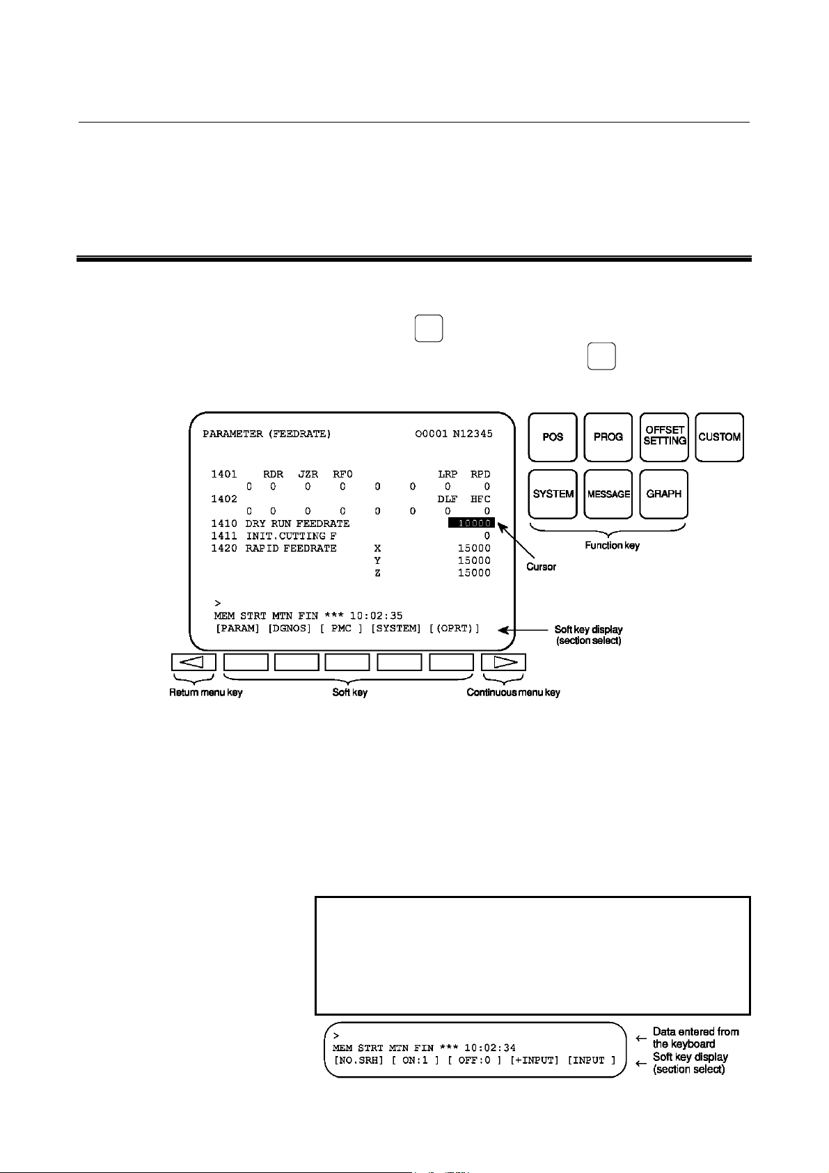
1 DISPLAYING PARAMETERS
Follow the procedure below to display parameters.
SYSTEM
(1) Press the
required, or alternatively, press the
then the [PARAM] section display soft key. The parameter
screen is then selected.
function key on the MDI as many times as
SYSTEM
function key once,
(2) The parameter screen consists of multiple pages. Use step (a) or
(b) to display the page that contains the parameter you want to
display.
(a) Use the page select key or the cursor move keys to display
the desired page.
(b) Enter the data number of the parameter you want to display
from the keyboard, then press the [NO.SRH] soft key. The
parameter page containing the specified data number
appears with the cursor positioned at the data number. (The
NOTE
If key entry is started with the section select soft
data is displayed in reverse video.)
keys displayed, they are replaced automatically by
operation select soft keys including [NO.SRH].
Pressing the [(OPRT)] soft key can also cause the
operation select keys to be displayed.
- 1 -
Page 14
2.SETTING PARAMETERS FROM MDI B-63530EN/03
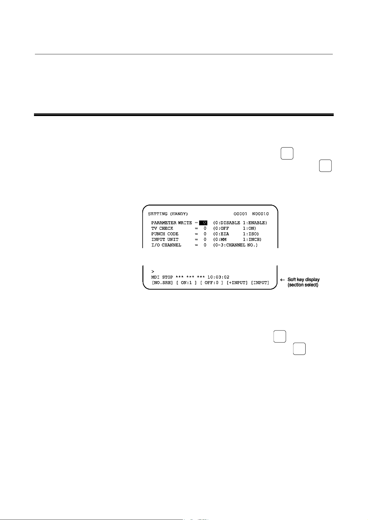
2 SETTING PARAMETERS FROM MDI
Follow the procedure below to set parameters.
(1) Place the NC in the MDI mode or the emergency stop state.
(2) Follow the substeps below to enable writing of parameters.
OFFSET
SETTING
1. To display the setting screen, press the
as many times as required, or alternatively press the
function key once, then the [SETTING] section select soft
key. The first page of the setting screen appears.
2. Position the cursor on "PARAMETER WRITE" using the
cursor move keys.
function key
OFFSET
SETTING
3. Press the [(OPRT)] soft key to display operation select soft
keys.
4. To set "PARAMETER WRITE=" to 1, press the [ON:1]
soft key, or alternatively enter 1 and press the [INPUT] soft
key. From now on, the parameters can be set. At the same
time an alarm condition (P/S100 PARAMETER WRITE
ENABLE) occurs in the CNC.
SYSTEM
(3) To display the parameter screen, press the
many times as required, or alternatively press the
key once, then the [PARAM] section select soft key.
(See Chapter 1 "DISPLAYING PARAMETERS.")
(4) Display the page containing the parameter you want to set, and
position the cursor on the parameter. (See Chapter 1
"DISPLAYING PARAMETERS.")
function key as
SYSTEM
function
- 2 -
Page 15
B-63530EN/03 2.SETTING PARAMETERS FROM MDI
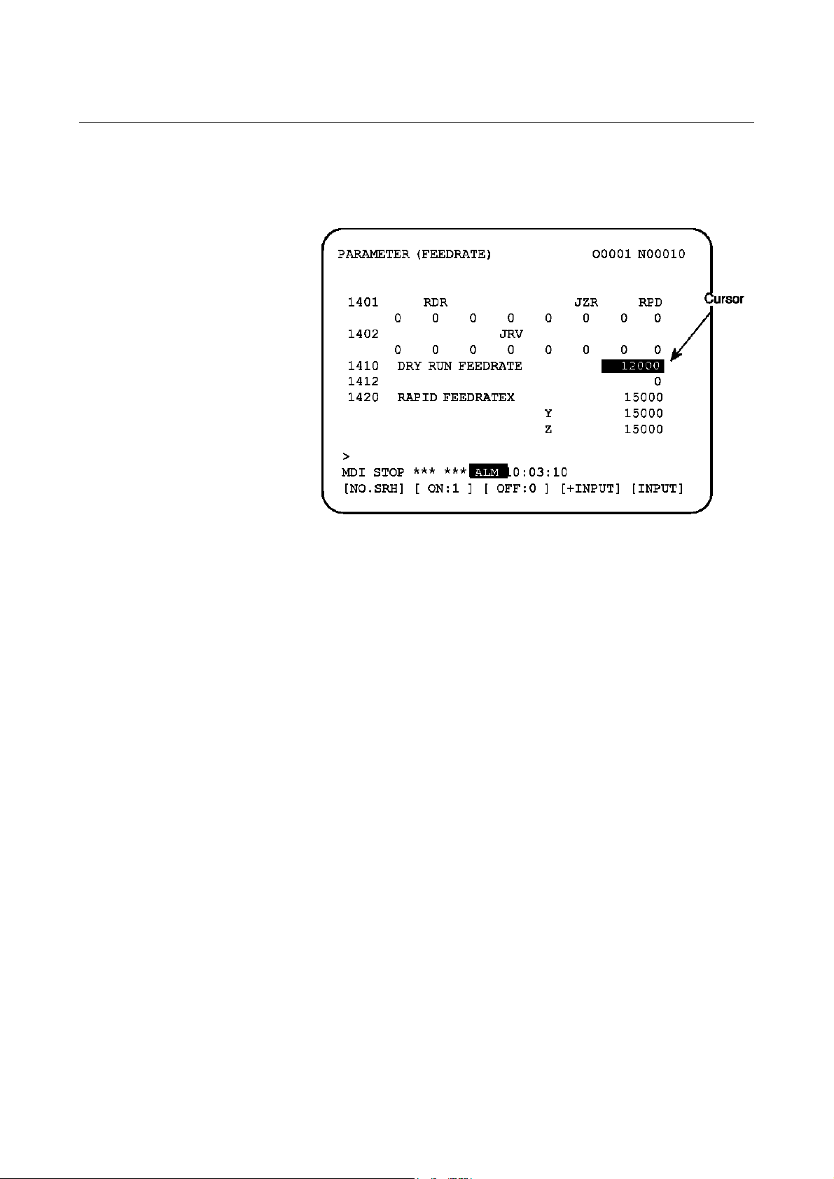
(5) Enter data, then press the [INPUT] soft key. The parameter
indicated by the cursor is set to the entered data.
[Example] 12000 [INPUT]
Data can be entered continuously for parameters, starting at
the selected parameter, by separating each data item with a
semicolon (;).
[Example]
Entering 10;20;30;40 and pressing the [INPUT] key assigns
values 10, 20, 30, and 40 to parameters in order starting at
the parameter indicatedby the cursor.
(6) Repeat steps (4) and (5) as required.
(7) If parameter setting is complete, set "PARAMETER WRITE="
to 0 on the setting screen to disable further parameter setting.
(8) Reset the NC to release the alarm condition (P/S100).
If an alarm condition (P/S000 PLEASE TURN OFF POWER)
occurs in the NC, turn it off before continuing operation.
- 3 -
Page 16

3.INPUTTING AND OUTPUTTING PARAMETERS THROUGH THE READER/PUNCHER INTERFACE B-63530EN/03
3 INPUTTING AND OUTPUTTING
PARAMETERS THROUGH THE
READER/PUNCHER INTERFACE
This section explains the parameter input/output procedures for
input/output devices connected to the reader/puncher interface.
The following description assumes the input/output devices are ready
for input/output. It also assumes parameters peculiar to the
input/output devices, such as the baud rate and the number of stop bits,
have been set in advance. (See Section 4.2.)
- 4 -
Page 17
B-63530EN/03 3.INPUTTING AND OUTPUTTING PARAMETERS THROUGH THE READER/PUNCHER INTERFACE
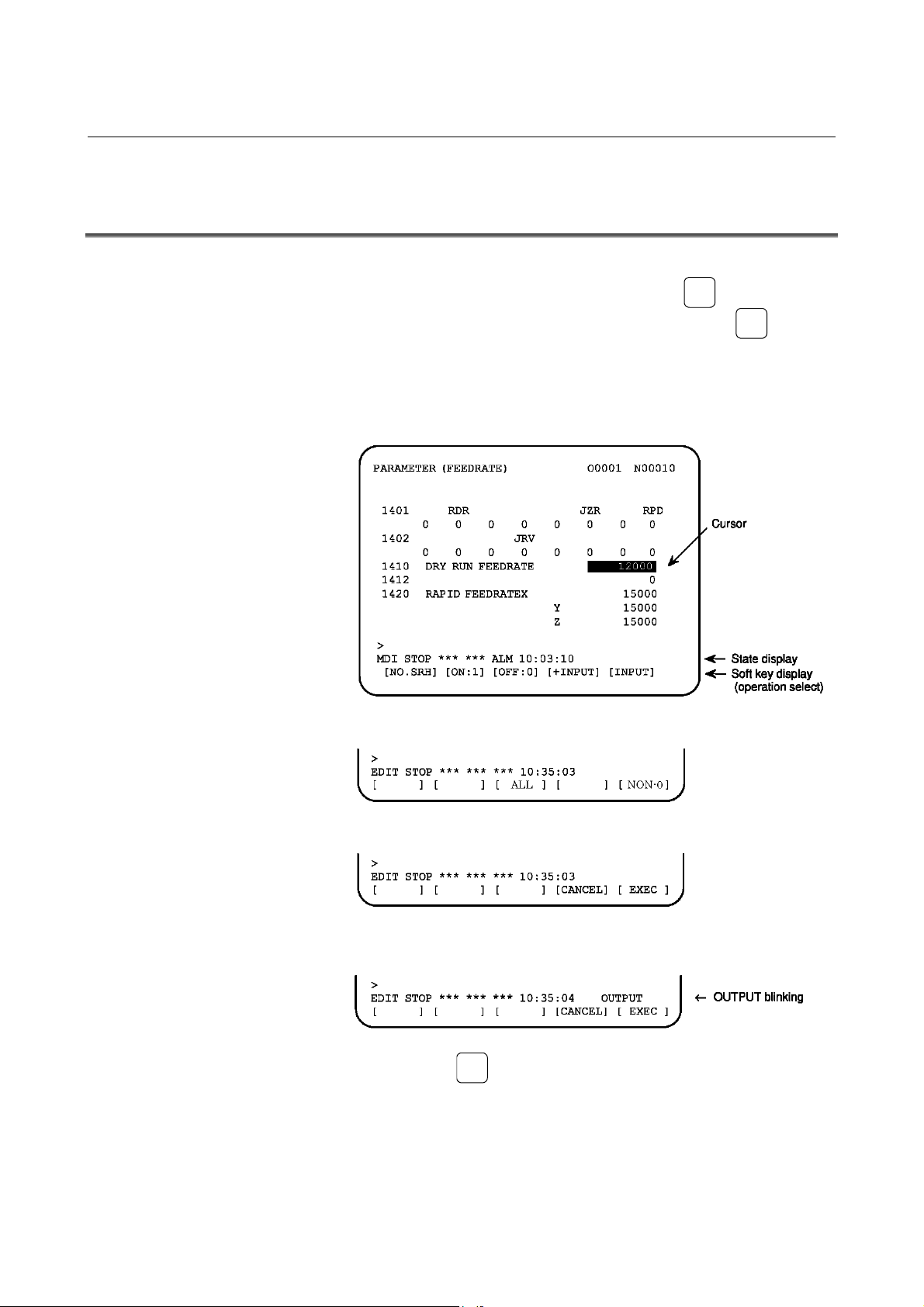
3.1 OUTPUTTING PARAMETERS THROUGH THE
READER/PUNCHER INTERFACE
(1) Select the EDIT mode or set to Emergency stop.
SYSTEM
(2) To select the parameter screen, press the
many times as required, or alternatively press the
key once, then the [PARAM] section select soft key.
(3) Press the [(OPRT)] soft key to display operation select soft keys,
then press the forward menu key located at the right-hand side of
the soft keys to display another set of operation select keys
including [PUNCH].
function key as
SYSTEM
function
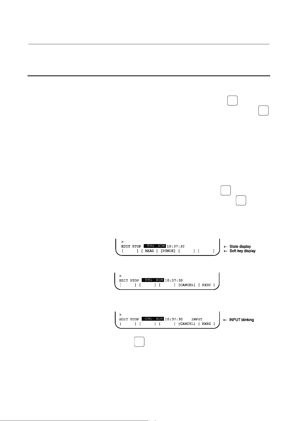
(4) Pressing the [ALL] or [NON-0]soft key changes the soft key
display as shown below:
(5) Pressing the [PUNCH] soft key changes the soft key display as
shown below:
(6) Press the [EXEC] soft key to start parameter output. When
parameters are being output, "OUTPUT" blinks in the state
display field on the lower part of the screen.
(7) When parameter output terminates, "OUTPUT" stops blinking.
Press the
RESET
key to interrupt parameter output.
- 5 -
Page 18
3.INPUTTING AND OUTPUTTING PARAMETERS THROUGH THE READER/PUNCHER INTERFACE B-63530EN/03
3.2 INPUTTING PARAMETERS THROUGH THE
READER/PUNCHER INTERFACE
(1) Place the NC in the emergency stop state.
(2) Enable parameter writing.
OFFSET
SETTING
1. To display the setting screen, press the
as many times as required, or alternatively press the
function key once, then the [SETTING] section select soft
key. The first page of the setting screen appears.
2. Position the cursor on "PARAMETER WRITE" using the
cursor move keys.
3. Press the [(OPRT)] soft key to display operation select soft
keys.
4. To set "PARAMETER WRITE=" to 1, press the ON:1 soft
key, or alternatively enter 1, then press the [INPUT] soft
key. From now on, parameters can be set. At the same time
an alarm condition (P/S100 PARAMETER WRITE
ENABLE) occurs in the NC.
(3) To select the parameter screen, press the
SYSTEM
function key
OFFSET
SETTING
function key as
SYSTEM
many times as required, or alternatively press the
key once,
then [PARAM] soft key.
(4) Press the [(OPRT)] soft key to display operation select keys, then
press the forward menu key located at the right-hand side of the
soft keys to display another set of operation select soft keys
including [READ].
(5) Pressing the [READ] soft key changes the soft key display as
shown below:
(6) Press the [EXEC] soft key to start inputting parameters from the
input/output device. When parameters are being input, "INPUT"
blinks in the state display field on the lower part of the screen.
(7) When parameter input terminates, "INPUT" stops blinking. Press
RESET
the
key to interrupt parameter input.
(8) When parameter read terminates, "INPUT" stops blinking, and
an alarm condition (P/S000) occurs in the NC. Turn it off before
continuing operation.
- 6 -
Page 19

B-63530EN/03 4.DESCRIPTION OF PARAMETERS
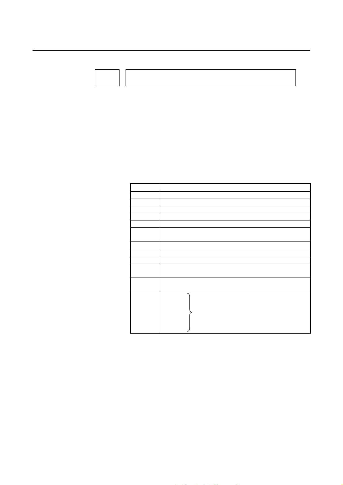
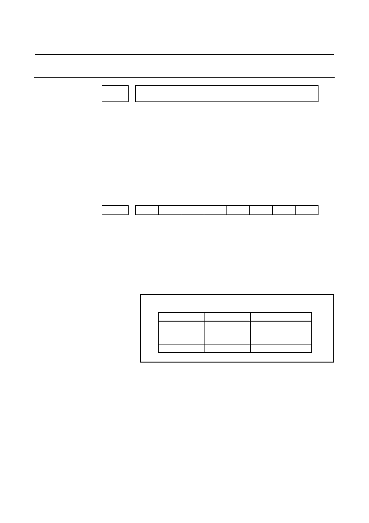
4 DESCRIPTION OF PARAMETERS
Parameters are classified by data type as follows:
Table 4 Data Types and Valid Data Ranges of Parameters
Data type Valid data range Remarks
Bit
Bit axis
Byte
Byte axis
Word
Word axis
2-word
2-word axis
NOTE
1 For the bit type and bit axis type parameters, a
single data number is assigned to 8 bits. Each bit
has a different meaning.
2 The axis type allows data to be set separately for
each control axis.
3 The valid data range for each data type indicates a
general range. The range varies according to the
parameters. For the valid data range of a specific
parameter, see the explanation of the parameter.
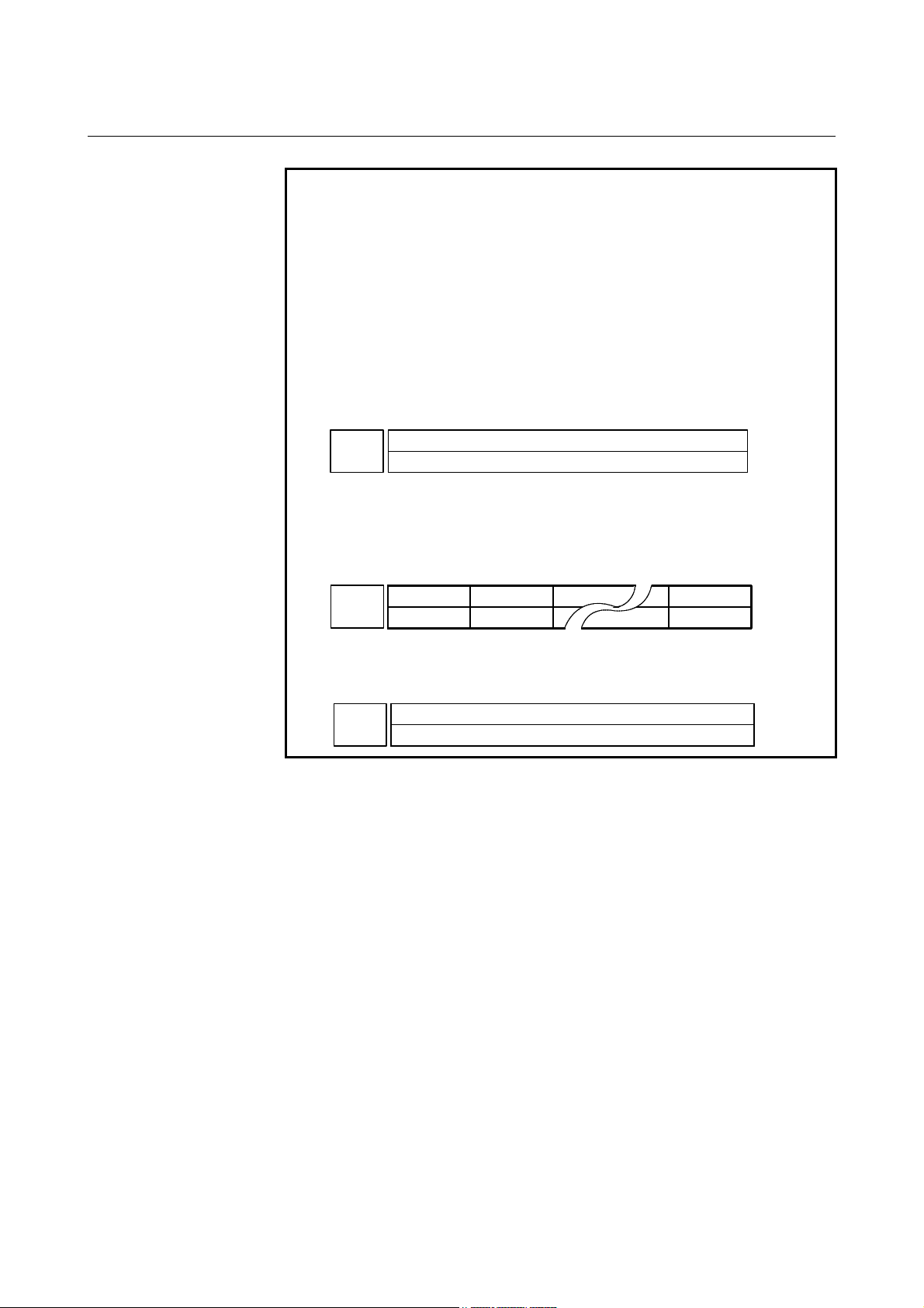
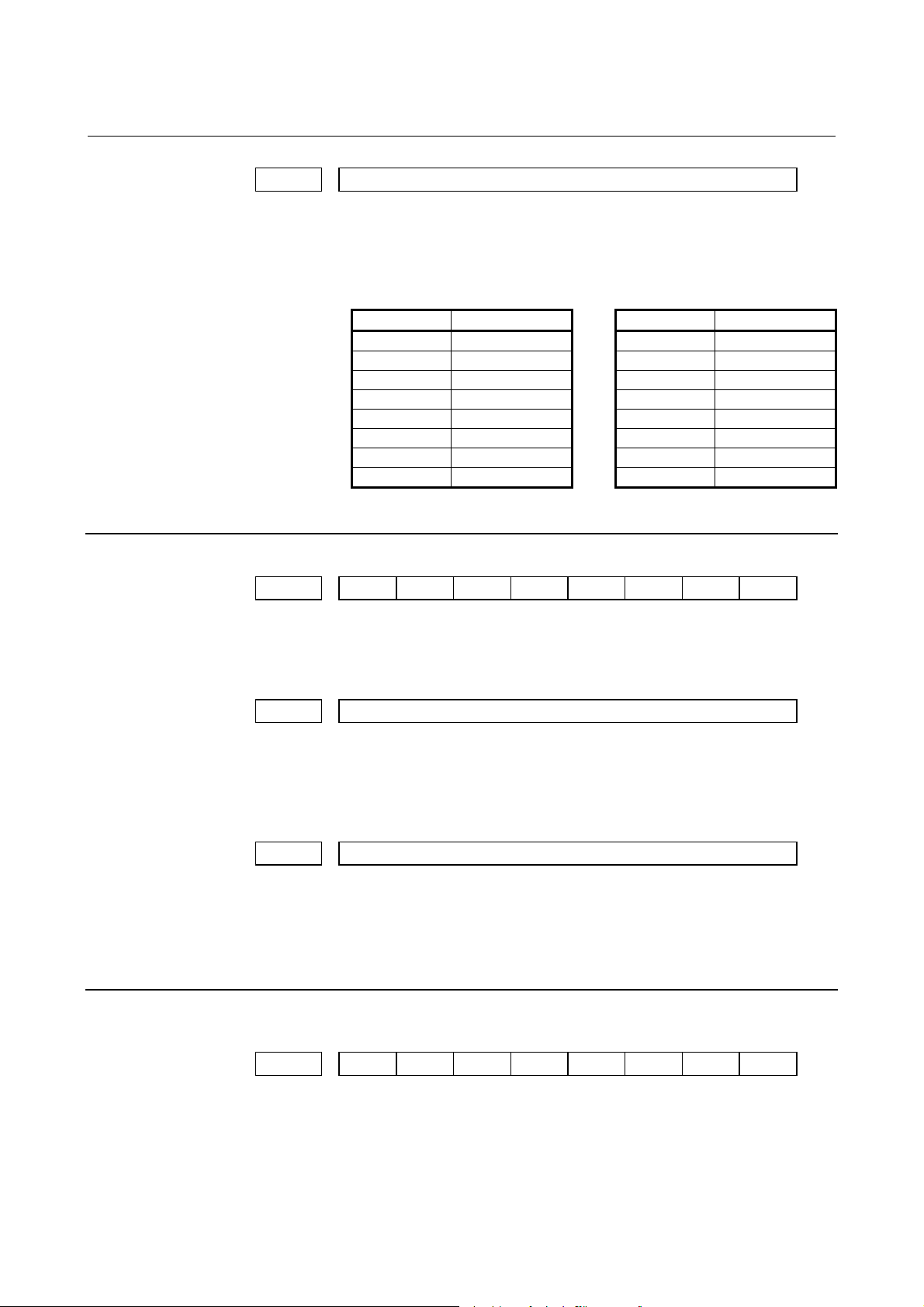
(1) Notation of bit type and bit axis type parameters
#7 #6 #5 #4 #3 #2 #1 #0
0000 SEQ INI ISO TVC
Data No. Data #0 to #7 are bit positions.
1023 Number of the servo axis for each axis
Data No. Data.
(2) Notation of parameters other than bit type and bit axis type
0 or 1
-128 to 127
0 to 255
-32768 to 32767
0 to 65535
-99999999 to 99999999
In some parameters, signs are
ignored.
In some parameters, signs are
ignored.
- 7 -
Page 20
4.DESCRIPTION OF PARAMETERS B-63530EN/03
NOTE
1 The bits left blank in Chapter 4 “DESCRIPTION OF
PARAMETERS” and parameter numbers that appear on
the display but are not found in the parameter list are
reserved for future expansion. They must always be 0.
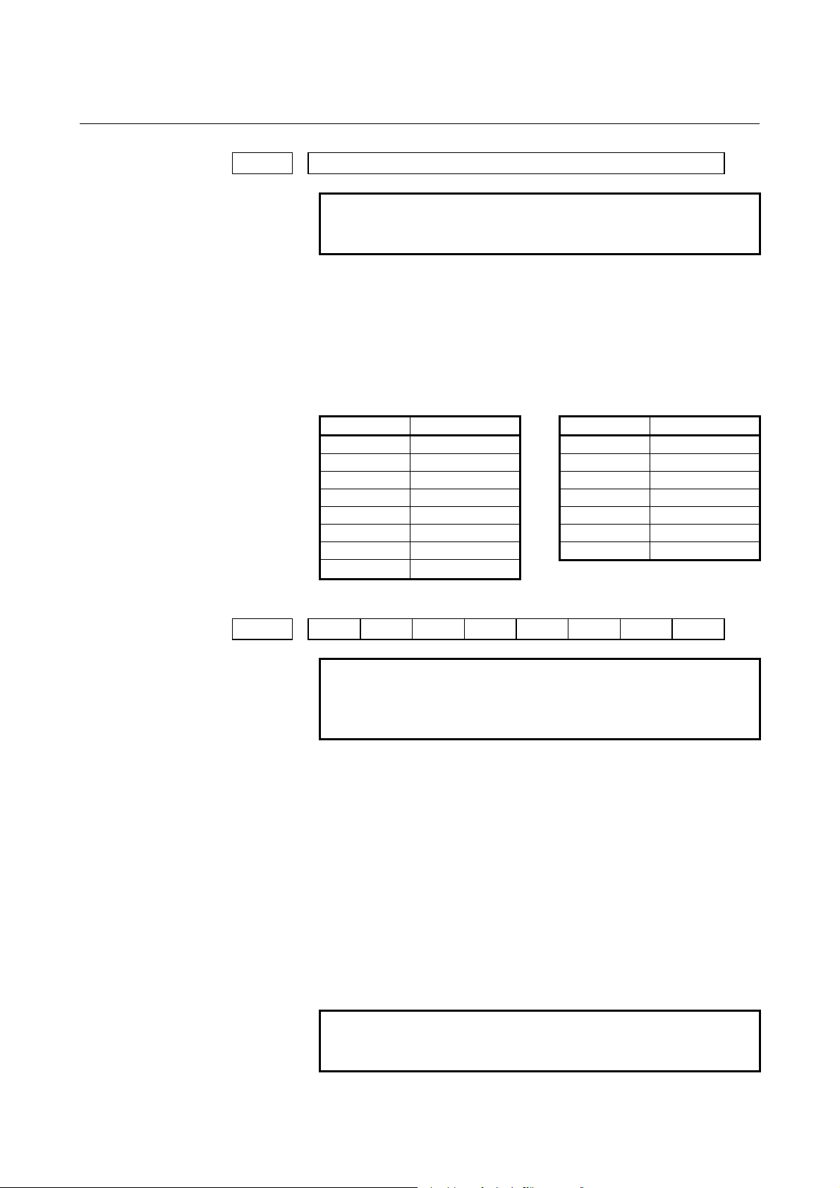
2 Parameters having different meanings between the T
series and M series and parameters that are valid only for
the T or M series are indicated in two levels as shown
below. Parameters left blank are unavailable.
[Example1]
Parameter No. 5010 has different meanings for the T
series and M series.
5010
Tool nose radius compensation ...
Tool compensation C ...
T series
M series
[Example2]
DPI is a parameter common to the M and T series, but
GSB and GSC are parameters valid only for the T
series.
#7 #6 #0
3401
GSC GSB DPI
DPI
T series
M series
[Example3]
The following parameter is provided only for the M
series.
1450
F1 digit feed ...
T series
M series
- 8 -
Page 21

B-63530EN/03 4.DESCRIPTION OF PARAMETERS
4.1 PARAMETERS OF SETTING
#7 #6 #5 #4 #3 #2 #1 #0
0000 SEQ INI ISO TVC
At least one of these parameters can also be set on the “Setting
screen”.
[Data type] Bit
TVC TV check
0 : Not performed
1 : Performed
ISO Code used for data output
0 : EIA code
1 : ISO code
INI Unit of input
0 : In mm
1 : In inches
SEQ Automatic insertion of sequence numbers
0 : Not performed
1 : Performed
When a program is prepared by using MDI keys in the part program
storage and edit mode, a sequence number can automatically be
assigned to each block in set increments. Set the increment to
parameter No. 3216.
#7 #6 #5 #4 #3 #2 #1 #0
0001 FCV
At least one of these parameters can also be set on the “Setting
screen”.
[Data type] Bit
FCV Tape format
0 : Series 16 standard format
1 : Series 15 format
NOTE
1 Programs created in the Series 15 tape format can
be used for operation on the following functions:
(1) Subprogram call M98
(2) Threading with equal leads G32 (T series)
(3) Canned cycle G90, G92, G94 (T series)
(4) Multiple repetitive canned cycle G71 to G76 (T
series)
(5) Drilling canned cycle G73, G74, G76, G80 to
G89 (M series)
(6) Cutter compensation C (M series)
2 When the tape format used in the Series 15 is used
for this CNC, some limits may add. Refer to the
Series 16i/18i/160i/180i/160is/180is-MODEL B
OPERATOR'S MANUAL.
- 9 -
Page 22

4.DESCRIPTION OF PARAMETERS B-63530EN/03
#7 #6 #5 #4 #3 #2 #1 #0
0002 SJZ RDG
At least one of these parameters can also be set on the “Setting
screen”.
[Data type] Bit
RDG Remote diagnosis is
0 : Not performed.
1 : Performed.
To use an RS-232C serial port for performing remote diagnosis,
connect and setup the modem, cable, and the like, then set 1 in this
parameter. When using a modem card, the setting is not necessary.
SJZ Manual reference position is performed as follows:
0 : When no reference position has been set, reference position
return is performed using deceleration dogs. When a reference
position is already set, reference position return is performed
using rapid traverse and deceleration dogs are ignored.
1 : Reference position return is performed using deceleration dogs at
all times.
NOTE
SJZ is enabled when bit 3 (HJZ) of parameter
No.1005 is set to 1. When a reference position is
set without a dog, (i.e. when bit 1 (DLZ) of
parameter No.1002 is set to 1 or bit 1 (DLZx) of
parameter No.1005 is set to 1) reference position
return after reference position setting is performed
using rapid traverse at all times, regardless of the
setting of SJZ.
#7 #6 #5 #4 #3 #2 #1 #0
0012
RMVx AICx MIRx
RMVx MIRx
At least one of these parameters can also be set on the “Setting
screen”.
[Data type] Bit axis
MIRx Mirror image for each axis
0 : Mirror image is off.
1 : Mirror image is on.
AICx The travel distance of an axis command is:
0 : Determined by the value specified with the address.
1 : Always handled as an incremental value.
RMVx Releasing the assignment of the control axis for each axis
0 : Not released
1 : Released
NOTE
RMVx is valid when bit 7 (RMBx) of parameter No.
1005 is 1.
- 10 -
Page 23
B-63530EN/03 4.DESCRIPTION OF PARAMETERS
0020
I/O CHANNEL: Selection of an input/output device or selection of input
device in the foreground
This parameter can also be set on the “Setting screen”.
[Data type] Byte
[Valid data range] 0 to 35
The CNC provides the following interfaces for data transfer to and
from the host computer and external input/output devices:
• Input/output device interface (RS-232C serial port 1 or 2)
• Remote buffer interface (RS-232C/RS-422)
• DNC1/DNC2 interface
In addition, data can be transferred to and from the power mate CNC
via the FANUC I/O Link.
This parameter selects the interface used to transfer data to and from
an input/output device.
Setting Description
0 or 1 RS-232C serial port 1
2 RS-232C serial port 2
3 Remote buffer interface
4 Memory card interface (NC side)
5 Data server interface
6
7 Memory card interface (touch panel side)
10 DNC1/DNC2 interface, OSI-Ethernet
12 DNC1 interface #2
15
16
20
21
22
to
34
35
The DNC operation is performed or M198 is specified by
FOCAS1/Ethernet or DNC1/Ethernet.
M198 is specified by FOCAS1/HSSB. (Bit 1 (NWD) of
parameter No. 8706) must also be specified.)
The DNC operation is performed or M198 is specified by
FOCAS1/ HSSB (port 2).
Group 0
Group 1
Group 2
to
Group 14
Group 15
Data is transferred between the CNC and a
power mate CNC in group n (n: 0 to 15) via the
FANUC I/O Link.
Supplemental remark 1
If the DNC operation is performed with FOCAS1/HSSB, the
setting of parameter No. 20 does not matter. The DMMC signal
<G042.7> is used.
Supplemental remark 2
If bit 0 (IO4) of parameter No. 110 is set to control the I/O
channels separately, the I/O channels can be divided into four
types: input and output in the foreground and input and output in
the background. If so, parameter No. 20 becomes a parameter for
selecting the input device in the foreground.
- 11 -
Page 24
4.DESCRIPTION OF PARAMETERS B-63530EN/03
(
)
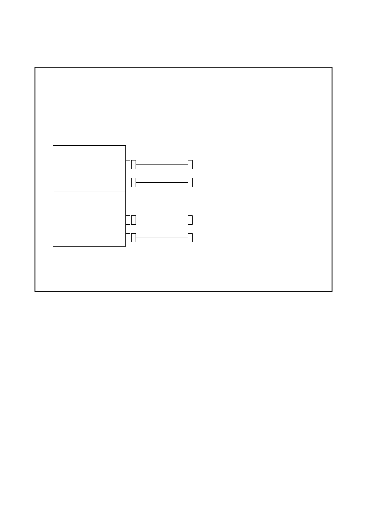
NOTE
1 An input/output device can also be selected using the setting screen. Usually, the
setting screen is used.
2 The specifications (such as the baud rate and the number of stop bits) of the
input/output devices to be connected must be set in the corresponding parameters
for each interface beforehand. (See Section 4.2.) I/O CHANNEL = 0 and I/O
CHANNEL = 1 represent input/output devices connected to RS-232C serial port 1.
Separate parameters for the baud rate, stop bits, and other specifications are
provided for each channel.
Motherboard
RS-232C serial port 1
R232-1(JD36A)
RS-232C serial port 2
Serial communication board
Remote buffer board
DNC1 board
DNC2 board
JD36B
R232-2
R232-3(JD28A)
R422-1(JD6A)
I/O CHANNEL=0, 1
(Channel 1)
I/O CHANNEL=2
(Channel 2)
I/O CHANNEL=3
(Channel 3)
I/O CHANNEL=3
(Channel 3)
RS-232-C I/O device
RS-232-C I/O device
RS-232-C I/O device
(when a remote buffer or DNC2 board is used)
RS-422 I/O device
(when a remote buffer or DNC1 board is used)
3 The input/output device interface may be referred to as the reader/puncher
interface.
RS-232C serial port 1 and RS-232C serial port 2 are also referred to as channel 1
and channel 2, respectively. The remote buffer interface is also referred to as
channel 3.
- 12 -
Page 25

B-63530EN/03 4.DESCRIPTION OF PARAMETERS
0021 Setting of the output device in the foreground
0022 Setting of the input device in the background
0023 Setting of the output device in the background
These parameters can also be set on the “Setting screen”.
[Data type] Byte
[Valid data range] 0 to 3, 5, 10
These parameters are valid only when bit 0 (IO4) of parameter No.
110 is set to control the I/O channels separately.
The parameters set individual input/output devices if the I/O channels
are divided into these four types: input and output in the foreground
and input and output in the background. The input device in the
foreground is set in parameter No. 20. For the details of the settings,
see the table provided with the description of parameter No. 20.
NOTE
If different input/output devices are simultaneously
used in the foreground and background, just a
value from 0 to 3 can be specified for the
background device.
If an attempt is made to use a busy input/output
device, an alarm (P/S233 or BP/S233) will be
raised. Note that the settings 0 and 1 indicate the
same input/output device.
- 13 -
Page 26

4.DESCRIPTION OF PARAMETERS B-63530EN/03
4.2 PARAMETERS OF READER/PUNCHER INTERFACE OR
REMOTE BUFFER
To exchange data (such as programs and parameters) with an external
input/output device by using the input/output device interface
(RS-232C serial port) or remote buffer interface, the parameters
described below need to be set.
In the setting parameter I/O CHANNEL, specify which of the
input/output devices connected to the three channels (RS-232C serial
port 1, RS-232C serial port 2, and remote buffer interface) is to be
used.
Furthermore, set the specifications (specification number, baud rate,
the number of stop bits, and so forth) of the input/output device
connected to each channel in the parameters corresponding to each
channel beforehand.
For setting of the specifications of channel 1, two sets of parameters
are available.
Fig. 4.2 shows the input/output device interface parameters
corresponding to each channel.
Input/output channel number (parameter No.0020)
↓
No. 0020
Specify a channel for an
input/output device.
I/O CHANNEL
=0 : Channel 1
=1 : Channel 1
=2 : Channel 2
=3 : Channel 3
I/O CHANNEL
I/O CHANNEL=0
(channel 1)
I/O CHANNEL=1
(channel 1)
I/O CHANNEL=2
(channel 2)
I/O CHANNEL=3
(channel 3)
No. 0101
No. 0102
No. 0103
No. 0111
No. 0112
No. 0113
No. 0121
No. 0122
No. 0123
No. 0131
No. 0132
No. 0133
No. 0134
No. 0135
Stop bit and other data
Number specified for the input/output
Baud rate
Stop bit and other data
Number specified for the input/output
Baud rate
Stop bit and other data
Number specified for the input/output
Baud rate
Stop bit and other data
Number specified for the input/output
Baud rate
Selection of protocol
Selection of RS-422 or RS-232C, and
other data
- 14 -
Page 27
B-63530EN/03 4.DESCRIPTION OF PARAMETERS
4.2.1 Parameters Common to all Channels
0024
[Data type] Byte
#7 #6 #5 #4 #3 #2 #1 #0
0100 ENS IOP ND3 NCR CRF CTV
[Data type] Bit
CTV: Character counting for TV check in the comment section of a
CRF EOB (end of block) to be output in the ISO code:
NCR Output of the end of block (EOB) in ISO code
Port for communication with the PMC ladder development tool (FANUC
LADDER-III)
This parameter can also be set on the “Setting screen”.
This parameter sets the port to be used for communication with the
PMC ladder development tool (FANUC LADDER-III).
0 : According to the setting on the PMC online screen
1 : RS-232C serial port 1 (JD36A)
2 : RS-232C serial port 2 (JD36B)
10 : High-speed interface (HSSB (COP7) or Ethernet)
11 : High-speed interface or RS-232C serial port 1
12 : High-speed interface or RS-232C serial port 2
program.
0 : Performed
1 : Not performed
0 : Depends on the setting of bit 3 (NCR) of parameter No. 100.
1 : is "CR""LF".
NOTE
The EOB output patterns are as shown below:
NCR CRF EOB output format
0 0 "LF" "CR" "CR"
0 1 "CR" "LF"
1 0 "LF"
1 1 "CR" "LF"
0 : LF, CR, CR are output.
1 : Only LF is output.
- 15 -
Page 28

4.DESCRIPTION OF PARAMETERS B-63530EN/03
ND3 In DNC operation, a program is:
0 : Read block by block. (A DC3 code is output for each block.)
1 : Read continuously until the buffer becomes full. (A DC3 code is
output when the buffer becomes full.)
NOTE
In general, reading is performed more efficiently
when ND3 set to 1. This specification reduces the
number of buffering interruptions caused by
reading of a series of blocks specifying short
movements. This in turn reduces the effective cycle
time.
IOP Specifies how to stop program input/output operations.
0 : An NC reset can stop program input/output operations.
1 : Only the [STOP] soft key can stop program input/output
operations. (A reset cannot stop program input/output
operations.)
ENS Action taken when a NULL code is found during read of EIA code
0 : An alarm is generated.
1 : The NULL code is ignored.
#7 #6 #5 #4 #3 #2 #1 #0
0110 IO4
[Data type] Bit
IO4 Separate control of I/O channel numbers is:
0 : Not performed.
1 : Performed.
If the I/O channels are not separately controlled, set the input/output
device in parameter No. 20.
If the I/O channels are separately controlled, set the input device and
output device in the foreground and the input device and output device
in the background in parameters No. 20 to No. 23 respectively.
Separate control of I/O channels makes it possible to perform
background editing, program input/output, and the like during the
DNC operation.
4.2.2 Parameters of Channel 1 (I/O CHANNEL=0)
#7 #6 #5 #4 #3 #2 #1 #0
0101
[Data type] Bit
SB2 The number of stop bits
NFD ASI SB2
NFD ASI HAD SB2
0 : 1
1 : 2
- 16 -
Page 29

B-63530EN/03 4.DESCRIPTION OF PARAMETERS
HAD An alarm raised for the internal handy file is:
0 : Not displayed in detail on the NC screen. (PS alarm 86 is
displayed.)
1 : Displayed in detail on the NC screen.
ASI Code used at data input/output
0 : EIA or ISO code (Input: Automatic determination/Output:
Setting of bit 1 (ISO) of parameter No. 0000)
1 : ASCII code for both input and output
NOTE
When using ASCII code for data input/output (when
setting ASI to 1), set also bit 1 (ISO) of parameter
No. 0000 to 1.
NFD Feed before and after the data at data output
0 : Output
1 : Not output
NOTE
When input/output devices other than the FANUC
PPR are used, set NFD to 1.
0102
[Data type] Byte
Number specified for the input/output device (when the I/O CHANNEL is set
to 0)
Set the number specified for the input/output device used when the
I/O CHANNEL is set to 0, with one of the set values listed in Table
4.2.2 (a).
Table 4.2.2 (a)
Set value Input/output device
0 RS-232C (Used control codes DC1 to DC4)
1
2 FANUC CASSETTE ADAPTOR 3 (FANUC CASSETTE F1)
3
4 RS-232C (Not used control codes DC1 to DC4)
5 Portable tape reader
6
FANUC CASSETTE ADAPTOR 1 (FANUC CASSETTE B1/
B2)
FANUC PROGRAM FILE Mate, FANUC FA Card Adaptor
FANUC FLOPPY CASSETTE ADAPTOR, FANUC Handy File
FANUC SYSTEM P-MODEL H
FANUC PPR
FANUC SYSTEM P-MODEL G, FANUC SYSTEM P-MODEL H
- 17 -
Page 30
4.DESCRIPTION OF PARAMETERS B-63530EN/03
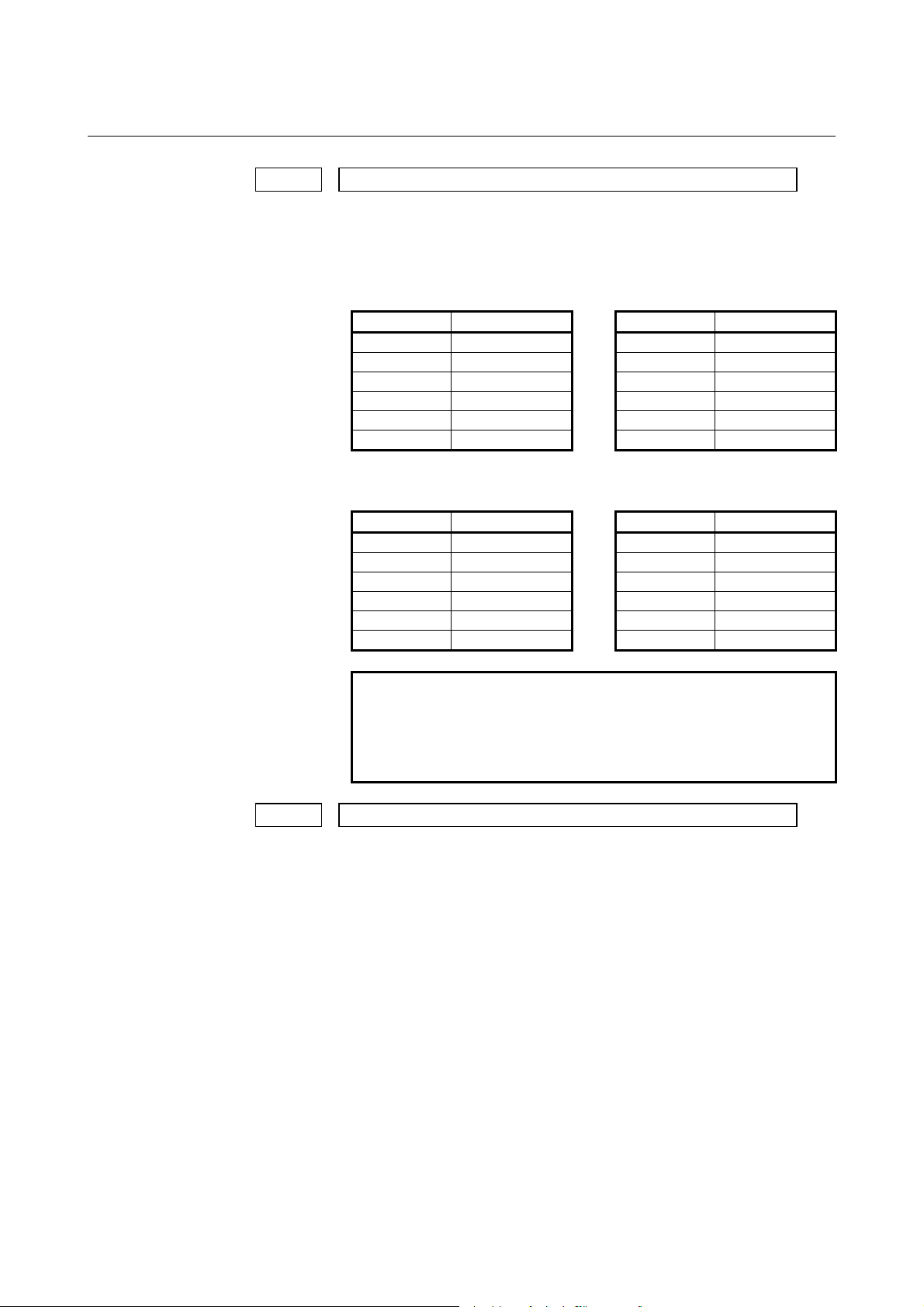
0103 Baud rate (when the I/O CHANNEL is set to 0)
[Data type] Byte
Set baud rate of the input/output device used when the I/O
CHANNEL is set to 0, with a set value in Table 4.2.2 (b).
Table 4.2.2 (b)
Set value Baud rate (bps) Set value Baud rate (bps)
1 50 9 2400
2 100 10 4800
3 110 11 9600
4 150 12 19200
5 200 13 38400
6 300 14 57600
7 600 15 76800
8 1200
16 115200
4.2.3 Parameters of Channel 1 (I/O CHANNEL=1)
#7 #6 #5 #4 #3 #2 #1 #0
0111 NFD ASI SB2
[Data type] Bit
These parameters are used when I/O CHANNEL is set to 1. The
meanings of the bits are the same as for parameter No. 0101.
0112 Number specified for the input/output device (when I/O CHANNEL is set to 1)
[Data type] Byte
Set the number specified for the input/output device used when
the I/O CHANNEL is set to 1, with one of the set values listed in
Table 4.2.2 (a).
0113 Baud rate (when I/O CHNNEL is set to 1)
[Data type] Byte
Set the baud rate of the input/output device used when I/O
CHANNEL is set to 1, with a value in Table 4.2.2 (b).
4.2.4 Parameters of Channel 2 (I/O CHANNEL=2)
#7 #6 #5 #4 #3 #2 #1 #0
0121 NFD ASI SB2
[Data type] Bit
These parameters are used when I/O CHANNEL is set to 2. The
meanings of the bits are the same as for parameter No. 0101.
- 18 -
Page 31

B-63530EN/03 4.DESCRIPTION OF PARAMETERS
0122 Number specified for the input/output device (when I/O CHANNEL is set to 2)
[Data type] Byte
Set the number specified for the input/output device used when I/O
CHANNEL is set to 2, with a value in Table 4.2.2 (a).
0123 Baud rate (when the I/O CHANNEL is set to 2)
[Data type] Byte
Set the baud rate of the input/output device used when I/O
CHANNEL is set to 2, with a value in Table 4.2.2 (b).
4.2.5 Parameters of Channel 3 (I/O CHANNEL=3)
#7 #6 #5 #4 #3 #2 #1 #0
0131 NFD ASI SB2
NOTE
When at least one of these parameters is set, the
power must be turned off before operation is
continued.
[Data type] Bit
These parameters are used when I/O CHANNEL is set to 3. The
meanings of the bits are the same as for parameter No. 0101.
0132 Number specified for the input/output device (when I/O CHANNEL is set to 3)
NOTE
When this parameter is set, the power must be
turned off before operation is continued.
[Data type] Byte
Set the number specified for the input/output device used when I/O
CHANNEL is set to 3, with a number in Table 4.2.2 (a).
- 19 -
Page 32
4.DESCRIPTION OF PARAMETERS B-63530EN/03
0133 Baud rate (when the I/O CHANNEL is set to 3)
NOTE
When this parameter is set, the power must be
turned off before operation is continued.
[Data type] Byte
Set the baud rate of the input/output device used when the I/O
CHANNEL is set to 3 according to the table 4.2.5.
Valid data range: 1 to 15 (up to a baud rate of 86400 bps) for the
RS-422 interface or 1 to 12 (up to a baud rate of 19200 bps) for the
RS-232C interface.
Table 4.2.5
Set value Baud rate (bps) Set value Baud rate (bps)
1 50 9 2400
2 100 10 4800
3 110 11 9600
4 150 12 19200
5 200 13 38400
6 300 14 76800
7 600 15 86400
8 1200
#7 #6 #5 #4 #3 #2 #1 #0
0134 CLK NCD SYN PRY
NOTE
When at least one of these parameters is set, the
power must be turned off before operation is
continued.
[Data type] Bit
PRY Parity bit
0 : Not used
1 : Used
SYN Reset/alarm in protocol B
0 : Not reported to the host
1 : Reported to the host with SYN and NAK codes
NCD CD (signal quality detection) of the RS-232C interface
0 : Checked
1 : Not checked
CLK Baud rate clock when the RS-422 interface is used
0 : Internal clock
1 : External clock
NOTE
When the RS-232C interface is used, set this bit to
0.
- 20 -
Page 33

B-63530EN/03 4.DESCRIPTION OF PARAMETERS
#7 #6 #5 #4 #3 #2 #1 #0
0135 RMS R42 PRA ETX ASC
NOTE
When at least one of these parameters is set, the
power must be turned off before operation is
continued.
[Data type] Bit
ASC Communication code except NC data
0 : ISO code
1 : ASCII code
ETX End code for protocol A or extended protocol A
0 : CR code in ASCII/ISO
1 : ETX code in ASCII/ISO
NOTE
Use of ASCII/ISO is specified by bit 0 (ASC) of
parameter No. 135.
PRA Communication protocol
0 : Protocol B
1 : Protocol A
R42 Interface
0 : RS-232C interface
1 : RS-422 interface
RMS State of remote/tape operation when protocol A is used
0 : Always 0 is returned.
1 : Contents of the change request of the remote/tape operation in
the SET command from the host is returned.
#7 #6 #5 #4 #3 #2 #1 #0
0138
[Data type] Bit
MDP In data output by a memory card, the series information is:
FNL In data output by RS-232C of the loader control function, the series
BIO In multi-path control, NC data input/output via the memory card
OWM When NC data or NC programs are punched to the memory card, a
MDN OWN BIO FNL MDP
MDN OWN FNL MDP
0 : Not added to the output file name.
1 : Added to the output file name.
information is:
0 : Not added to the output file name.
1 : Added to the output file name.
interface is:
0 : Controlled on a path-by-path basis.
1 : Controlled in a batch for all paths.
file overwrite confirmation message is:
0 : Displayed.
1 : Not displayed.
- 21 -
Page 34

4.DESCRIPTION OF PARAMETERS B-63530EN/03
MDN The DNC operation function by a memory card is:
0 : Disabled.
1 : Enabled. (A PCMCIA card attachment is required.)
NOTE
Use a PCMCIA card attachment suited to the CNC
to secure the memory card in the CNC.
- 22 -
Page 35

B-63530EN/03 4.DESCRIPTION OF PARAMETERS
4.3 PARAMETERS OF DNC1/DNC2 INTERFACE
#7 #6 #5 #4 #3 #2 #1 #0
0140 ECD NCE BCC
NOTE
When at least one of these parameters is set, the
power must be turned off before operation is
continued.
[Data type] Bit
BCC The BCC value (block check characters) is:
0 : Checked.
1 : Not checked.
This parameter is dedicated to the DNC2 interface.
Even if the BCC value is not checked, the BCC value itself must be
specified.
NCE The ER (RS-232C) and TR (RS422) signals are:
0 : Checked.
1 : Not checked.
This parameter is dedicated to the DNC2 interface.
ECD Error code of negative acknowledgment
0 : A four-digit hexadecimal error code is added to a negative
acknowledgment.
1 : No error code is added to a negative acknowledgment.
This parameter is dedicated to the DNC2 interface.
NOTE
To use FANUC DNC2 communications library for
the host computer, set this parameter to 1.
0141 System for connection between the CNC and host (DNC1 interface)
NOTE
When this parameter is set, the power must be
turned off before operation is continued.
[Data type] Byte
[Valid data range] 1 or 2
This parameter specifies the system for connection (DNC1 interface)
between the CNC and host.
Set value
1 : Point-to-point connection
2 : Multipoint connection
- 23 -
Page 36

4.DESCRIPTION OF PARAMETERS B-63530EN/03
0142 Station address of the CNC (DNC1 interface)
NOTE
When this parameter is set, the power must be
turned off before operation is continued.
[Data type] Byte
[Valid data range] 2 to 52
This parameter specifies the station address of the CNC when the
CNC is connected via the DNC1 interface using multipoint
connection.
0143 Time limit specified for the timer monitoring a response (DNC2 interface)
NOTE
When this parameter is set, the power must be
turned off before operation is continued.
[Data type] Byte
[Unit of data] sec
[Valid data range] 1 to 60 (The standard setting is 3.)
0144 Time limit specified for the timer monitoring the EOT signal (DNC2 interface)
NOTE
When this parameter is set, the power must be
turned off before operation is continued.
[Data type] Byte
[Unit of data] sec
[Valid data range] 1 to 60 (The standard setting is 5.)
0145 Time required for switching RECV and SEND (DNC2 interface)
NOTE
When this parameter is set, the power must be
turned off before operation is continued.
[Data type] Byte
[Unit of data] sec
[Valid data range] 1 to 60 (The standard setting is 1.)
- 24 -
Page 37

B-63530EN/03 4.DESCRIPTION OF PARAMETERS
0146 Number of times the system retries holding communication (DNC2 interface)
NOTE
When this parameter is set, the power must be
turned off before operation is continued.
[Data type] Byte
[Unit of data] Number of times
[Valid data range] 1 to 10 (The standard setting is 3.)
Set the maximum number of times the system retries holding
communication with the remote device if the remote device uses an
invalid protocol in the data-link layer or the remote device does not
respond to the request.
0147
Number of times the system sends the message in response to the NAK
signal (DNC2 interface)
NOTE
When this parameter is set, the power must be
turned off before operation is continued.
[Data type] Byte
[Unit of data] Number of times
[Valid data range] 1 to 10 (The standard setting is 2.)
Set the maximum number of times the system retries sending the
message in response to the NAK signal.
0148 Number of characters in overrun (DNC2 interface)
NOTE
When this parameter is set, the power must be
turned off before operation is continued.
[Data type] Byte
[Valid data range] 10 to 225 (The standard setting is 10.)
Set the number of characters the system can receive after transmission
is stopped (CS off).
- 25 -
Page 38

4.DESCRIPTION OF PARAMETERS B-63530EN/03
0149
Number of characters in the data section of the communication packet
(DNC2 interface)
NOTE
When this parameter is set, the power must be
turned off before operation is continued.
[Data type] Word
[Valid range] 80 to 256 (The standard setting is 256.)
If the specified value is out of range, a value of 80 or 256 is used.
The standard setting is 256.
This parameter determines the maximum length of the packet used in
transmission over the DNC2 interface. Including the two characters at
the start of the packet, the four characters used for a command, and the
three characters at the end, the maximum number of characters in the
packet is nine plus the number specified in parameter No.0149.
Length of the packet
DLE
STX
2 bytes 4 bytes 80 to 256 bytes 3 bytes
Command Data section DEL ETX BCC
- 26 -
Page 39

B-63530EN/03 4.DESCRIPTION OF PARAMETERS
4.4 PARAMETERS OF M-NET INTERFACE
#7 #6 #5 #4 #3 #2 #1 #0
0161 SRS PEO SRP SRL
NOTE
When at least one of these parameters is set, the
power must be turned off before operation is
continued.
[Data type] Bit
SRL Number of characters used in the serial interface
0 : Seven bits
1 : Eight bits
SRP Vertical parity in the serial interface
0 : Vertical parity is not checked.
1 : Vertical parity is checked.
PEO Either odd or even parity is used for vertical parity in the serial
interface
0 : Odd parity is used.
1 : Even parity is used.
NOTE
This bit is effective when bit SRP is set to 1.
SRS Stop bit in the serial interface
0 : One stop bit is used.
1 : Two stop bits are used.
0171 Length of DI data in bytes in M-NET
NOTE
When this parameter is set, the power must be
turned off before operation is continued.
[Data type] Byte
[Valid range] 1 to 32
Specify the length of DI data in bytes (number of byte of data actually
transferred from the PLC unit to the CNC unit) in the serial interface.
- 27 -
Page 40

4.DESCRIPTION OF PARAMETERS B-63530EN/03
0172 Length of DO data in bytes in M-NET
NOTE
When this parameter is set, the power must be
turned off before operation is continued.
[Data type] Byte
[Valid range] 1 to 32
Specify the length of DO data in bytes (number of bytes of data
actually transferred from the CNC unit to the PLC unit) in the serial
interface.
NOTE
When a self-loop test is performed, specify the
same value in parameters No.0171 and No.0172.
0173 Station address in M-NET
NOTE
When this parameter is set, the power must be
turned off before operation is continued.
[Data type] Byte
[Valid range] 1 to 15
Specify a station address in the serial interface.
0174 Baud rate in M-NET
NOTE
When this parameter is set, the power must be
turned off before operation is continued.
[Data type] Byte
[Valid range] 0 to 6 (The standard setting is 3.)
Specify a baud rate for the serial interface.
Set value Baud rate (bps)
1 2400
2 4800
3 9600
4 19200
5 38400
6 57600
7 76800
- 28 -
Page 41

B-63530EN/03 4.DESCRIPTION OF PARAMETERS
0175 Time required for connecting two stations in M-NET
NOTE
When this parameter is set, the power must be
turned off before operation is continued.
[Data type] Word
[Unit of data] msec
[Valid range] 1 to 32767 (The standard setting is 10000.)
Specify a time limit from when the connection sequence is completed
for the self-station to when the normal transfer sequence starts in the
serial interface.
0176 Time required for polling in M-NET
NOTE
When this parameter is set, the power must be
turned off before operation is continued.
[Data type] Word
[Unit of data] msec
[Valid data range] 1 to 32767 (The standard setting is 500.)
Specify a time limit for polling in the normal sequence at the
self-station in the serial interface.
0177 Time required from SAI to BCC in M-NET
NOTE
When this parameter is set, the power must be
turned off before operation is continued.
[Data type] Word
[Unit of data] msec
[Valid data range] 1 to 32767 (The standard setting is 50.)
Specify a time limit from when the SAI signal starts to be transferred
to when the BCC signal has been sent.
0178 Time between a reception and the next transmission in M-NET
NOTE
When this parameter is set, the power must be
turned off before operation is continued.
[Data type] Word
[Unit of data] msec
[Valid data range] 1 to 32767 (The standard setting is 1.)
Specify the time from when data has been received to when the next
data starts to be transmitted.
- 29 -
Page 42

4.DESCRIPTION OF PARAMETERS B-63530EN/03
4.5 PARAMETERS OF REMOTE DIAGNOSIS
#7 #6 #5 #4 #3 #2 #1 #0
0002 RDG
[Data type] Bit
RDG Remote diagnosis is:
0 : Not performed.
1 : Performed.
If an RS-232C serial port is used to carry out remote diagnosis,
connect and set up the modem, cable, and the like, then set 1 in this
parameter. When using a modem card, the setting is not necessary.
#7 #6 #5 #4 #3 #2 #1 #0
0201 MCB NCR ASC SB2
[Data type] Bit
SB2 The number of stop bits is
0 : 1.
1 : 2.
To carry out remote diagnosis, set 0.
ASC The code to be used for data output is:
0 : ISO code.
1 : ASCII code.
To carry out remote diagnosis, set 1.
NCR EOB (end of block) is output as:
0 : "LF""CR""CR".
1 : Just as "LF".
To carry out remote diagnosis, set 1.
MCB The baud rate setting for data input/output between the modem card
and CNC is:
0 : 9600 bps (fixed).
1 : Determined by the setting of parameter No. 203.
For the detailed setting while MCB is set to 1, see parameter No. 203.
- 30 -
Page 43
B-63530EN/03 4.DESCRIPTION OF PARAMETERS
0203 Baud rate (for remote diagnosis)
[Data type] Byte
Set the baud rate of data input/output by remote diagnosis, with
reference to the tables given below.
When using an RS-232C serial port
Set value Baud rate (bps) Set value Baud rate (bps)
1 50 7 600
2 100 8 1200
3 110 9 2400
4 150 10 4800
5 200 11 9600
6 300
12 19200
When using a modem card (when bit 6 (MCB) of parameter No. 201
is set to 1)
Set value Baud rate (bps) Set value Baud rate (bps)
1 28800 7 600
2 38400 8 1200
3 57600 9 2400
4 - 10 4800
5 - 11 9600
6 300
12 19200
NOTE
The tables above indicate the baud rates of
communication between the CNC and modem. The
actual communication baud rate may be lowered,
depending on the modem and communication line.
0204 Remote diagnosis channel
[Data type] Byte
[Valid data range] 0, 1, 2
The interface to be used for remote diagnosis is:
0,1 : RS-232C serial port 1 (channel 1).
2 : RS-232C serial port 2 (channel 2).
To carry out remote diagnosis using RS-232C, the reader/puncher
interface is required.
- 31 -
Page 44

4.DESCRIPTION OF PARAMETERS B-63530EN/03
0211 Password 1 for remote diagnosis
0212 Password 2 for remote diagnosis
0213 Password 3 for remote diagnosis
[Data type] 2-word
[Valid data range] 1 to 99999999
Specify a password for using the remote diagnosis function.
The remote diagnosis function has the following password settings.
Data can be protected by preventing a third party from accessing any
system parameter or machining program without permission.
Password 1:
Set a password for the whole service of the remote diagnosis
function. (The whole remote diagnosis service is available only
when this password is input on the host side (PC, for instance).)
Password 2:
Set a password of a part program. (The input/output, verification,
and the like of a program are possible only when this password is
input on the host side (PC, for instance).)
Password 3:
Set a password of a parameter. (The input/output or the like of a
parameter is possible only when this password is input on the
host side (PC, for instance).)
NOTE
Once any value other than 0 is specified as a
password, the password can be changed only
when the same value is specified in the
corresponding keyword (parameters No. 221 to No.
223). If any value other than 0 is specified as a
password, the password setting is not displayed on
the parameter screen (blank display is provided).
Take great care when setting the password.
- 32 -
Page 45

B-63530EN/03 4.DESCRIPTION OF PARAMETERS
0221 Keyword 1 for remote diagnosis
0222 Keyword 2 for remote diagnosis
0223 Keyword 3 for remote diagnosis
[Data type] 2-word
[Valid range] 1 to 99999999
Set a keyword corresponding to a password of the remote diagnosis
function.
Keyword 1: Keyword for password 1 (parameter No. 211)
Keyword 2: Keyword for password 2 (parameter No. 212)
Keyword 3: Keyword for password 3 (parameter No. 213)
If any value other than 0 is specified as a password (parameters No.
211 to No. 213), the password can be changed only when the same
value is specified as the corresponding keyword.
NOTE
The keyword value is reset to 0 at power-up. On
the parameter screen, the keyword setting is not
displayed (blank display is provided).
- 33 -
Page 46
4.DESCRIPTION OF PARAMETERS B-63530EN/03
4.6 PARAMETERS OF DNC1 INTERFACE #2
#7 #6 #5 #4 #3 #2 #1 #0
0231 NFD ASI SB2
NOTE
When at least one of these parameters is set, the
power must be turned off before operation is
continued.
[Data type] Bit
SB2 Number of stop bits
0 : 1 bit
1 : 2 bits
ASI Data input code
0 : IEA or ISO (automatic recognition)
1 : ASCII Code
NFD When data is out, feed holes are
0 : Output before and after data section
1 : Not output
0233 Baud rate (DNC1 interface #2)
NOTE
When this parameter is set, the power must be
turned off before operation is continued.
[Data type] Byte
[Valid data range] 1 to 15
Specify a baud rate.
Set value Baud rate (bps) Set value Baud rate (bps)
1 50 9 2400
2 100 10 4800
3 110 11 9600
4 150 12 19200
5 200 13 38400
6 300 14 76800
7 600 15 86400
8 1200
- 34 -
Page 47

B-63530EN/03 4.DESCRIPTION OF PARAMETERS
0241 Mode of connection between the host and CNC (DNC1 interface #2)
NOTE
When this parameter is set, the power must be
turned off before operation is continued.
[Data type] Byte
[Valid data range] 1 or 2
This parameter sets the mode of connection between the host and
CNC.
Setting Mode
1 Point-to-point mode
2 Multipoint mode
0242 CNC station address (DNC 1 interface #2)
NOTE
When this parameter is set, the power must be
turned off before operation is continued.
[Data type] Byte
[Valid data range] 2 to 52
This parameter sets a CNC station address when the CNC is to be
connected in the multipoint mode.
- 35 -
Page 48

4.DESCRIPTION OF PARAMETERS B-63530EN/03
4.7 PARAMETERS OF MEMORY CARD INTERFACE
#7 #6 #5 #4 #3 #2 #1 #0
0300 PCM
[Data type] Bit
PCM If the CNC screen display function is enabled, when a memory card
interface is provided on the NC side,
0 : The memory card interface on the NC side is used.
1 : The memory card interface on the PC side is used.
This parameter is valid when 4 (memory card interface) is set in
parameter No. 20. This parameter is valid only while the CNC screen
display function is active.
- 36 -
Page 49

B-63530EN/03 4.DESCRIPTION OF PARAMETERS
4.8 PARAMETERS OF FACTOLINK
#7 #6 #5 #4 #3 #2 #1 #0
0801 SB2
[Data type] Bit
SB2 The number of stop bits is:
0 : 1 bit.
1 : 2 bits.
(Set the number of stop bits when an RS-232C port is specified as the
FACTOLINK communication port.)
0802 Communication channel for the FACTOLINK
[Data type] Byte
Set the communication port for use with the FACTOLINK.
1 : RS-232C serial port 1
2 : RS-232C serial port 2
11 : Ethernet board port 1
12 : Ethernet board port 2
13 : Ethernet board port 3
21 : Embedded Ethernet
0803 Communication baud rate for the FACTOLINK
[Data type] Byte
Set the communication baud rate when an RS-232C port is specified
as the FACTOLINK communication port.
10 : 4800 bps
11 : 9600 bps
12 : 19200 bps (Recommendation value)
#7 #6 #5 #4 #3 #2 #1 #0
0810 FMN FTM FYR FCL FAS BGS
[Data type] Bit
BGS When the FACTOLINK screen is not displayed, FACTOLINK alarm
task communication is:
0 : Not activated.
1 : Activated.
FAS If FACTOLINK uses the Answer or AnswerEx command, the answer
number A01. is:
0 : Displayed in the answer field.
1 : Not displayed in the answer field.
FCL The FACTOLINK clock is:
0 : Not displayed in reverse video.
1 : Displayed in reverse video.
- 37 -
Page 50

4.DESCRIPTION OF PARAMETERS B-63530EN/03
FYR In the FACTOLINK clock display, years in the 99/01/23 00:00 format
(bit 4 (FTM) of parameter No. 0810 set to 1) are represented:
0 : By a two-digit number.
1 : By a four-digit number.
FTM The FACTOLINK clock is displayed in this format:
0 : Wed Nov 12 00:00:00
1 : 97/11/12 00:00:00
FMN The FACTOLINK screen is displayed:
0 : In color.
1 : With two levels of gray.
0811 Logging type for the FACTOLINK
[Data type] Byte
0812 PMC address of logging data for the FACTOLINK
[Data type] Word
0813 Logging data length for the FACTOLINK
[Data type] Word
0814 Logging wait address for the FACTOLINK
[Data type] Word
0815 FACTOLINK logging data transmission interval
[Data type] 2-word
0820 FACTOLINK device address (1)
0821 FACTOLINK device address (2)
0822 FACTOLINK device address (3)
0823 FACTOLINK device address (4)
0824 FACTOLINK device address (5)
0825 FACTOLINK device address (6)
0826 FACTOLINK device address (7)
0827 FACTOLINK device address (8)
0828 FACTOLINK device address (9)
[Data type] Byte
See following manuals for the parameters related to the FACTOLINK.
• FANUC Ethernet Board/DATA SERVER Board OPARATOR'S
MANUAL (B-63354EN)
• FANUC FACTOLINK SCRIPT FUNCTION OPERATOR'S
MANUAL (B-75054EN)
- 38 -
Page 51

B-63530EN/03 4.DESCRIPTION OF PARAMETERS
4.9 PARAMETERS OF DATA SERVER
#7 #6 #5 #4 #3 #2 #1 #0
0900 ONS DSV
[Data type] Bit
DSV The data server function is
0 : Enabled
1 : Disabled
ONS When the O number of the data server file name and the O number in
an NC program do not match:
0 : The O number of the file name takes priority.
1 : The O number in the NC program takes priority.
0921 OS selected for host computer 1 of data server
0922 OS selected for host computer 2 of data server
0923 OS selected for host computer 3 of data server
[Data type] Word
[Valid data range] 0 to 1
0 : Windows95/98/NT is selected.
1 : UNIX or VMS is selected.
0924 Latency setting for DNC1/Ethernet or FOCAS1/Ethernet
[Data type] Word
[Unit of data] msec
[Valid data range] 0 to 255
Set service latency of DNC1/Ethernet or FOCAS1/Ethernet while
DNC1/Ethernet or FOCAS1/Ethernet is used together with the data
server function.
If a value between 0 and 2 is set, 2 msec is assumed.
- 39 -
Page 52

4.DESCRIPTION OF PARAMETERS B-63530EN/03
4.10 PARAMETERS OF ETHERNET
0931 Special character code corresponding to soft key [CHAR-1]
0932 Special character code corresponding to soft key [CHAR-2]
0933 Special character code corresponding to soft key [CHAR-3]
0934 Special character code corresponding to soft key [CHAR-4]
0935 Special character code corresponding to soft key [CHAR-5]
[Data type] Byte
[Valid data range] 32 to 95
These parameters are provided to allow a special character that is not
provided on the MDI panel but needed in a user name, password, or
login DIR to be input by pressing a soft key on the Ethernet parameter
screen.
If a value other than 0 is input as a parameter, the special character
assigned to the corresponding input soft key [CHAR-1] to [CHAR-5]
is displayed.
The special character codes correspond to the ASCII codes.
Sample special character codes
Special
character
Blank 32 ) 41 < 60
! 33 * 42 > 62
" 34 + 43 ? 63
# 35 , 44 @ 64
$ 36 - 45 [ 91
% 37 . 46 ^ 92
& 38 / 47 # 93
' 39 : 58 ] 94
( 40 ; 59 _ 95
Code
Special
character
Code
Special
character
Code
- 40 -
Page 53

B-63530EN/03 4.DESCRIPTION OF PARAMETERS
4.11 PARAMETERS OF POWER MATE CNC MANAGER
#7 #6 #5 #4 #3 #2 #1 #0
0960 2CH ASG SPW PMN MD2 MD1 SLV
[Data type] Bit
SLV When the power mate CNC manager is selected, the screen displays:
0 : One slave.
1 : Up to four slaves with the screen divided into four.
MD1,MD2 These parameters set a slave parameter input/output destination.
MD2 MD1 Input/output destination
0 0 Part program storage
0 1 Memory card
In either case, slave parameters are output in program format.
PMN The power mate CNC manager function is:
0 : Enabled.
1 : Disabled. (Communication with slaves is not performed.)
SPW With the power mate CNC manager, slave parameters:
0 : Can be set at all times, regardless of the setting of PWE.
1 : Follow the setting of PWE.
ASG Whether the number of bytes allocated to the input/output destination
of the β amplifier with the I/O Link is 16 is:
0 : Not checked.
1 : Checked.
2CH The power mate CNC manager communicates with:
0 : Channel 2
1 : Channel 1
NOTE
1 This parameter is valid only when I/O Link point
extension (to 2 channels) is supported.
2 Even when this parameter is set to 0, the power
mate CNC manager communicates with channel 1
if no β amplifier with the I/O Link is connected with
channel 2.
3 When this parameter is set to 1, the power mate
CNC manager does not communicate with channel
2 if no β amplifier with the I/O Link is connected
with channel 1.
- 41 -
Page 54

4.DESCRIPTION OF PARAMETERS B-63530EN/03
4.12 PARAMETERS OF AXIS CONTROL/INCREMENT SYSTEM
#7 #6 #5 #4 #3 #2 #1 #0
1001 INM
NOTE
When at least one of these parameters is set, the
power must be turned off before operation is
continued.
[Data type] Bit
INM Least command increment on the linear axis
0 : In mm (metric system machine)
1 : In inches (inch system machine)
#7 #6 #5 #4 #3 #2 #1 #0
1002
[Data type] Bit
JAX Number of axes controlled simultaneously in jog feed, manual rapid
DLZ Function setting the reference position without dog
SFD The function for shifting the reference position is
IDG XIK SFD DLZ JAX
IDG XIK AZR SFD DLZ JAX
traverse and manual reference position return
0 : 1 axis
1 : 3 axes
0 : Disabled
1 : Enabled (enabled for all axes)
NOTE
1 This function can be specified for each axis by bit 1
(DLZx) of parameter No.1005.
2 For a system including an axis of Cs contour
control or spindle positioning, avoid using this
parameter. Use bit 1 (DLZx) of parameter No. 1005
instead to set just a required axis.
0 : Not used.
1 : Used.
- 42 -
Page 55

B-63530EN/03 4.DESCRIPTION OF PARAMETERS
AZR When no reference position is set, the G28 command causes:
0 : Reference position return using deceleration dogs (as during
manual reference position return) to be executed.
1 : P/S alarm No.090 to be issued.
NOTE
When the function for setting the reference position
without dogs (refer to bit 1 (DLZ) of parameter No.
1002) is used, the G28 command specified before
a reference position is set causes P/S alarm
No.090 to be issued, regardless of the setting of
AZR.
XIK When bit 1 (LRP) of parameter No.1401, is set to 0, namely, when
positioning is performed using non-linear type positioning, if an
interlock is applied to the machine along one of axes in positioning,
0 : The machine stops moving along the axis for which the interlock
is applied and continues to move along the other axes.
1 : The machine stops moving along all the axes.
IDG When the reference position is set without dogs, automatic setting of
bit 0 (IDGx) of parameter No.1012 to prevent the reference position
from being set again is:
0 : Not performed.
1 : Performed.
#7 #6 #5 #4 #3 #2 #1 #0
1004
IPR ISD ISC
IPR IPI ISC ISA
NOTE
When at least one of these parameters is set, the
power must be turned off before operation is
continued.
[Data type] Bit
ISA, ISC, ISD The least input increment and least command increment are set.
ISD ISC ISA
0 0 0 0.001 mm, 0.001 deg, or 0.0001 inch IS-B
0 0 1 0.01 mm, 0.01 deg, or 0.001 inch IS-A
0 1 0 0.0001 mm, 0.0001 deg, or 0.00001 inch IS-C
1 0 0 0.00001 mm, 0.00001 deg, or 0.000001 inch IS-D
Least input increment and least command
increment
Symbol
NOTE
IS-A cannot be used at present.
- 43 -
Page 56

4.DESCRIPTION OF PARAMETERS B-63530EN/03
IPI Bit 7 (IPR) of parameter No. 1004 is:
0 : Parameter that requires the power to be turned off before
continuation of operation and is invalid in the case of inch input.
1 : Parameter that does not require the power to be turned off before
continuation of operation and is valid even in the case of inch
input.
IPR Whether the least input increment for each axis is set to a value 10
times as large as the least command increment is specified, in
increment systems of IS-B or IS-C at setting mm.
0 : The least input increment is not set to a value 10 times as larg as
the least command increment.
1 : The least input increment is set to a value 10 times as large as the
least command increment.
If IPR is set to 1, the least input increment is set as follows:
Increment system Least input increment
IS-B 0.01 mm, 0.01 deg, or 0.0001 inch
IS-C 0.001 mm, 0.001 deg, or 0.00001 inch
NOTE
For IS-A, the least input increment cannot be set to
a value 10 times as large as the least command
increment.
The least input increment is not multiplied by 10
also when the pocket calculator type decimal point
programming (bit 0 (DPI) of parameter No. 3401) is
used.
- 44 -
Page 57

B-63530EN/03 4.DESCRIPTION OF PARAMETERS
#7 #6 #5 #4 #3 #2 #1 #0
1005 RMBx MCCx EDMx EDPx HJZx DLZx ZRNx
[Data type] Bit axis
ZRNx When a command specifying the movement except for G28 is issued
in automatic operation (memory, MDI, or DNC operation) and when a
return to the reference position has not been performed since the
power was turned on
0 : An alarm is generated (P/S alarm 224).
1 : An alarm is not generated.
NOTE
1 The state in which the reference position has not
been established refers to that state in which
reference position return has not been performed
after power-on when an absolute position detector
is not being used, or that state in which the
association of the machine position with the
position detected with the absolute position
detector has not been completed (see the
description of bit 4 (APZx) of parameter No. 1815)
when an absolute position detector is being used.
2 To use a function that establishes the reference
point and makes a movement with a command
other than G28, such as an axis of Cs contour
control, set this parameter for the relative axis.
3 When the Cs axis coordinate establishment
function (bit 2 (CSF) of parameter No. 3712) is
used, it is recommended to set this parameter to 0.
DLZx Function for setting the reference position without dogs
0 : Disabled
1 : Enabled
NOTE
1 This parameter is valid when bit 1 (DLZ) of
parameter No. 1002 is set to 0. When bit 1 (DLZ) of
parameter No. 1002 is set to 1, the function for
setting the reference position without dogs is
enabled for all axes, regardless of the setting of
this parameter.
2 Do not set this parameter for a Cs contour control
axis and spindle positioning axis.
- 45 -
Page 58

4.DESCRIPTION OF PARAMETERS B-63530EN/03
HJZx When a reference position is already set:
0 : Manual reference position return is performed with deceleration
dogs.
1 : Manual reference position return is performed using rapid
traverse without deceleration dogs, or manual reference position
return is performed with deceleration dogs, depending on the
setting of bit 7 (SJZ) of parameter No.0002.
NOTE
When the function for setting the reference position
without dogs (refer to bit 1 (DLZ) of parameter No.
1002) is used, positioning at the reference position
is performed at the rapid traverse rate at all times
in reference position return operation after
reference position establishment, regardless of the
setting of HJZ.
EDPx External deceleration signal in the positive direction for each axis
0 : Valid only for rapid traverse
1 : Valid for rapid traverse and cutting feed
EDMx External deceleration signal in the negative direction for each axis
0 : Valid only for rapid traverse
1 : Valid for rapid traverse and cutting feed
MCCx When an axis become the removal state using the controlled axis
removal signal or setting:
0 : MCC is turned off
1 : MCC is not turned off. (Servo motor excitation is turned off, but
the MCC signal of the servo amplifier is not turned off.)
NOTE
This parameter is used to remove only one axis, for
example, when a two-axis or three-axis amplifier is
used. When two-a axis or three-axis amplifier is
used and only one axis is removed, servo alarm
No.401 (V-READY OFF) is usually issued.
However, this parameter, when set to 1, prevents
servo alarm No.401 from being issued.
Note, however, that disconnecting a servo amplifier
from the CNC will cause the servo amplifier to
enter the V-READY OFF status. This is a
characteristic of all multiaxis amplifiers.
RMBx Releasing the assignment of the control axis for each axis (signal input
and setting input)
0 : Invalid
1 : Valid
- 46 -
Page 59

B-63530EN/03 4.DESCRIPTION OF PARAMETERS
#7 #6 #5 #4 #3 #2 #1 #0
1006
ZMIx DIAx ROSx ROTx
ZMIx ROSx ROTx
NOTE
When at least one of these parameters is set, the
power must be turned off before operation is
continued.
[Data type] Bit axis
ROTx, ROSx Setting linear or rotary axis.
ROSx ROTx Meaning
Linear axis
(1) Inch/metric conversion is done.
0 0
0 1
1 0 Setting is invalid (unused)
1 1
For the rotary axis used for cylindrical interpolation, set ROTx to 1.
For the C-axis (workpiece axis) used with the hobbing function, be
sure to set ROTx to 1.
DIAx Either a diameter or radius is set to be used for specifying the amount
of travel on each axis.
0 : Radius
1 : Diameter
(2) All coordinate values are linear axis type.
(Is not rounded in 0 to 360°.)
(3) Stored pitch error compensation is linear axis type
(Refer to parameter No.3624.)
Rotary axis (A type)
(1) Inch/metric conversion is not done.
(2) Machine coordinate values are rounded in 0 to 360°.
Absolute coordinate values or relative coordinate values
are rounded or not rounded by bit 0 (ROAx) or bit 2
(RRLx) of parameter No. 1008.
(3) Stored pitch error compensation is the rotation type.
(Refer to parameter No.3624)
(4) Automatic reference position return (G28, G30) is done
in the reference position return direction and the move
amount does not exceed one rotation.
Rotary axis (B type)
(1) Inch/metric conversion, absolute coordinate values and
relative coordinate values are not done.
(2) Machine coordinate values, absolute coordinate values,
and relative coordinate values are linear axis type. (Is
not rounded in 0 to 360°.)
(3) Stored pitch error compensation is linear axis type
(Refer to parameter No.3624.)
(4) Cannot be used with the rotary axis roll-over function
and the index table indexing function (M series).
- 47 -
Page 60

4.DESCRIPTION OF PARAMETERS B-63530EN/03
ZMIx The direction of reference position return on each axis.
0 : Positive direction
1 : Negative direction
NOTE
The direction of the initial backlash, which occurs
when power is switched on, is opposite to the
direction of a reference position return.
#7 #6 #5 #4 #3 #2 #1 #0
1007
[Data type] Bit axis
RTLx A reference position return operation performed on a rotary axis is of:
PRSx RAAx OKIx ALZx RTLx
RAAx OKIx
0 : Rotary axis type.
1 : Linear axis type.
NOTE
Reference position return operations of rotary axis
type and linear axis type differ from each other as
follows, depending on the timing for pressing a dog
(deceleration signal for reference position return):
Linear axis type:
If a dog is pressed before a one-rotation signal
is detected, P/S alarm No. 090 is issued.
Rotation type axis:
If a dig is pressed before a one-rotation signal is
detected, reference position return operation is
continued with no alarm issued.
ALZx In automatic reference position return:
0 : A reference position return operation is performed by positioning.
If no reference position return operation is performed after
power-on, a reference position return operation is performed
according to the same sequence as for manual reference position
return.
1 : A reference position return operation is performed according to
the same sequence as for manual reference position return.
NOTE
This parameter does not affect an axis on which a
reference position return operation is performed
without dogs.
- 48 -
Page 61

B-63530EN/03 4.DESCRIPTION OF PARAMETERS
OKIx Upon completion of reference position return in reference position
setting with mechanical stopper:
0 : P/S alarm 000 is issued.
(When reference position setting with mechanical stopper is used
with this parameter setting, an absolute-position detector is
needed.)
1 : P/S alarm 000 is not issued.
(Even when reference position setting with mechanical stopper is
used with this parameter setting, no absolute-position detector is
needed.)
RAAx When an absolute command is specified for a rotary axis:
0 : The end point coordinates and direction of rotation conform to
bit 1 (RABx) of parameter No.1008.
1 : The end point coordinates conform to the absolute value of the
value specified in the command. The rotational direction
conforms to the sign of the value specified in the command.
NOTE
1 This parameter is valid when the rotary axis control
function is provided and the rotary axis roll-over
function is applied (bit 0 (ROAx) of parameter
No.1008 is set to 1).
2 This parameter is equal to bit 3 (RAAx) of
parameter No.1008. After this parameter is set, the
power does not need to be turned off.
PRSx In automatic reference position return (G28), automatic coordinate
system presetting is:
0 : Not performed.
1 : Performed.
#7 #6 #5 #4 #3 #2 #1 #0
1008 RMCx RAAx RRLx RABx ROAx
NOTE
When at least one of these parameters is set, the
power must be turned off before operation is
continued.
[Data type] Bit axis
ROAx The rotary axis roll-over function is
0 : Invalid
1 : Valid
NOTE
ROAx specifies the function only for a rotary axis
(for which bit 0 (ROTx) of parameter No.1006 is set
to 1)
- 49 -
Page 62

4.DESCRIPTION OF PARAMETERS B-63530EN/03
RABx In the absolute commands, the axis rotates in the direction
0 : In which the distance to the target is shorter.
1 : Specified by the sign of command value.
NOTE
RABx is valid only when ROAx is set to 1.
RRLx Relative coordinates are
0 : Not rounded by the amount of the shift per one rotation
1 : Rounded by the amount of the shift per one rotation
NOTE
1 RRLx is valid only when ROAx is set to 1.
2 Assign the amount of the shift per one rotation in
parameter No.1260.
RAAx The rotation direction of a rotary axis and end point coordinates in the
absolute command mode:
0 : Agree with the setting of bit 1 (RABx) of parameter No.1008.
1 : Agree with the absolute value of the specified value for the end
point coordinates and the sign of the specified value for the
rotation direction.
NOTE
This parameter is enabled when the rotary axis
control function is provided and the rotary axis
roll-over function is used (with bit 0 (ROAx) of
parameter No.1008 set to 1).
RMCx When machine coordinate system selection (G53) or high-speed
machine coordinate system selection (G53P1) is used, bit 1 (RABx) of
parameter No. 1008 for setting the rotation direction of an absolute
command and bit 3 (RAAx) of parameter No. 1007 or parameter No.
1008 for rotary axis control used with the rotary axis roll-over
function are:
0 : Invalid.
1 : Valid.
- 50 -
Page 63

B-63530EN/03 4.DESCRIPTION OF PARAMETERS
1010 Number of CNC-controlled axes
NOTE
When this parameter is set, the power must be
turned off before operation is continued.
[Data type] Byte
[Valid data range] 1, 2, 3, ..., the number of controlled axes
Set the maximum number of axes that can be controlled by the CNC.
[Example] Suppose that the first axis is the X axis, and the second and
subsequent axes are the Y, Z, A, B, and C axes in that order, and that
they are controlled as follows:
X, Y, Z, and A axes: Controlled by the CNC
A axis: Controlled by the CNC and PMC
B and C axes: Controlled by the PMC
Then set this parameter to 4 (total 4: 1st to 4th axes)
With this setting, the fifth and sixth axes (B and C axes) are controlled
only by the PMC, and therefore cannot be controlled directly by the
CNC.
- 51 -
Page 64

4.DESCRIPTION OF PARAMETERS B-63530EN/03
#7 #6 #5 #4 #3 #2 #1 #0
1012 IDGx
[Data type] Bit axis
IDGx The function for setting the reference position again, without dogs, is:
0 : Not inhibited.
1 : Inhibited.
NOTE
1 IDGx is enabled when bit 7 (IDG) of parameter
No.1002 is set to 1.
2 When the function for setting the reference
position, without dogs, is used, and the reference
position is lost for some reason, an alarm
requesting reference position return (No.300) is
generated when the power is next turned on. If the
operator performs reference position return, as a
result of mistakenly identifying the alarm as that
requesting the operator to perform a normal
reference position return, an invalid reference
position may be set. To prevent such an operator
error, bit 0 (IDGx) of parameter No.1012 is
provided to prevent the reference position from
being set again without dogs.
(1) If bit 7 (IDG) of parameter No.1002 is set to 1,
bit 0 (IDGx) of parameter No.1012 is
automatically set to 1 when the reference
position is set using the function for setting the
reference position without dogs. This prevents
the reference position from being set again
without dogs.
(2) Once the reference position is prevented from
being set for an axis again, without dogs, any
attempt to set the reference position for the
axis without dogs results in the output of an
alarm (No.090).
(3) When the reference position must be set again
without dogs, set IDGx to 0 before setting the
reference position.
#7 #6 #5 #4 #3 #2 #1 #0
1015
[Data type] Bit
RHR After increment system (inch/metric) switching, for the rotary axis, the
DWT WIC SVS ZRL RHR
DWT WIC ZRL RHR
first G28 command causes reference position return:
0 : At a low speed.
1 : At a high speed/
- 52 -
Page 65

B-63530EN/03 4.DESCRIPTION OF PARAMETERS
ZRL For high-speed reference position return according to G28, second to
fourth reference position return according to G30, and G53 command:
0 : Non-linear type positioning is performed.
1 : Linear type positioning is performed.
This parameter is valid when bit 1 (LRP) of parameter No. 1401 is set
to 1.
SVS When the servo along an axis is turned off, simple synchronous
control is:
0 : Released.
1 : Not released.
WIC Workpiece origin offset measurement value direct input is:
0 : Valid only in the currently selected workpiece coordinate system.
1 : Valid in all coordinate systems.
NOTE
When this parameter is set to 0, a measurement
value direct input operation can be performed in
the currently selected workpiece coordinate system
or external workpiece coordinate system. A
warning is issued if an attempt is made for
measurement value direct input of any other
workpiece origin offset.
DWT When a dwell time is specified with P, the unit of data is:
0 : 1 msec when IS-B is used, or 0.1 msec when IS-C is used
1 : 1 msec (not dependent on the increment system)
- 53 -
Page 66

4.DESCRIPTION OF PARAMETERS B-63530EN/03
1020 Program axis name for each axis
[Data type] Byte axis
Set the program axis name for each controlled axis, using one of the
values listed in the following table:
Axis
name
Setting
X 88 U 85 A 65 E 69
Y 89 V 86 B 66 - Z 90 W 87 C 67 - -
Axis
name
Setting
Axis
name
Setting
Axis
name
Setting
NOTE
1 With the T series, when G code system A is used,
neither U, V, nor W can be used as an axis name.
Only when G code system B or C is used, U, V,
and W can be used as axis names.
2 The same axis name cannot be assigned to more
than one axis.
3 When the second auxiliary function is provided, the
address used by the second auxiliary function
(address B with the T series or, with the M series,
the address specified in parameter No.3460)
cannot be used as an axis name.
4 With the T series, when address C or A is used for
chamfering, corner rounding, or direct drawing
dimension programming (when the CCR parameter
(bit 4 of parameter No.3405) is set to 1), addresses
C or A cannot be used as an axis name.
5 Only with the T series, address E can be used as
an axis name. Address E cannot be used with the
M series. When address E is used as an axis
name, note the following:
• When G code system A is used, address E is
always assigned to an absolute command.
• When an equal-lead threading command (G32)
is issued in the Series 15 command format,
address E cannot be used to specify the thread
lead. Use address F to specify the thread lead.
- 54 -
Page 67

B-63530EN/03 4.DESCRIPTION OF PARAMETERS
1022 Setting of each axis in the basic coordinate system
NOTE
When this parameter is set, power must be turned
off before operation is continued.
[Data type] Byte axis
To determine the following planes used for circular interpolation,
cutter compensation C (for the M series), tool nose radius
compensation (for the T series), etc., each control axis is set to one of
the basic three axes X, Y, and Z, or an axis parallel to the X, Y, or Z
axis.
G17: Plane Xp-Yp
G18: Plane Zp-Xp
G19: Plane Yp-Zp
Only one axis can be set for each of the three basic axes X, Y, and Z,
but two or more parallel axes can be set.
Set value Meaning
0 Neither the basic three axes nor a parallel axis
1 X axis of the basic three axes
2 Y axis of the basic three axes
3 Z axis of the basic three axes
5 Axis parallel to the X axis
6 Axis parallel to the Y axis
7 Axis parallel to the Z axis
- 55 -
Page 68

4.DESCRIPTION OF PARAMETERS B-63530EN/03
1023 Number of the servo axis for each axis
NOTE
When this parameter is set, power must be turned
off before operation is continued.
[Data type] Byte axis
[Valid data range] 1, 2, 3, ..., number of controlled axes /-1,-2,-3,-4 (-4 can be used in
Series 16i/160i/160is only)
Set the servo axis for each control axis.
Usually set to same number as the control axis number.
The control axis number is the order number that is used for setting
the axis-type parameters or axis-type machine signals
To use a controlled axis as a spindle, specify -1.
Setting bit 7 (CSS) of parameter No. 3704 to 1 enables the second to
fourth serial spindles to be assigned as Cs contour axes.
When one of the second to fourth serial spindles is used as a Cs
contour axis, set a value from -2 to -4.
When Cs contour control is used for a virtual Cs axis, make a setting
for spindle assignment.
Refer to FSSB section of CONNECTION MANUAL (FUNCTION)
B-63523EN-1.
NOTE
1 When the dual check safety function is used, the
first servo axis is required at all times. When the
dual check safety function is used under multi-path
control, the first servo axis cannot be exchanged
between paths.
More details are provided below:
• For 1-path control, 1-CPU 2-path control, or
loader control
An axis with parameter No. 1023 set to 1 is
required for tool post 1 (or the loader).
• For 2-CPU 2-path control or 2-CPU 3-path
control
An axis with parameter No. 1023 set to 1 is
required for tool post 1, and an axis with
parameter No. 1023 set to 9 is required for tool
post 2.
2 For electric gear box controlled axes, two axes
needs to be paired as a set. So, make the following
setting:
• Set one of 1, 3, 5, and 7 for a slave axis. For a
dummy axis to be paired with the slave axis, set
a value obtained by adding 1 to the setting for
the slave axis.
- 56 -
Page 69

B-63530EN/03 4.DESCRIPTION OF PARAMETERS
1031 Reference axis
[Data type] Byte axis
[Valid data range] 1, 2, 3, ..., number of controlled axes
Some parameters for using high-precision/AI high-precision/AI nano
high-precision contour control are common to all axes. The unit of
some of those parameters varies according to the increment system.
The unit of such parameters is matched with the increment system of a
reference axis. This parameter is used to set the ordinal number of an
axis to be used as the reference axis.
If 0 is set, the specification of 1 is assumed.
- 57 -
Page 70

4.DESCRIPTION OF PARAMETERS B-63530EN/03
4.13 PARAMETERS OF COORDINATES
#7 #6 #5 #4 #3 #2 #1 #0
1201
[Data type] Bit
ZPR Automatic setting of a coordinate system when the manual reference
ZPI Coordinates at the reference position when a coordinate system is set
ZCL Local coordinate system when the manual reference position return is
FPC When the floating reference position is specified using soft keys on
AWK When the workpiece origin offset value is changed
WZR AWK FPC ZCL ZPI ZPR
AWK FPC ZCL ZPI ZPR
position return is performed
0 : Not set automatically
1 : Set automatically
NOTE
1 ZPR is valid while a workpiece coordinate system
function is not provided. If a workpiece coordinate
system function is provided, making a manual
reference position return always causes the
workpiece coordinate system to be established on
the basis of the workpiece origin offset (parameters
No. 1220 to No. 1226), irrespective of this
parameter setting.
2 If an absolute-position detector is used in a system
not using a workpiece coordinate system function,
set this parameter.
automatically
0 : Value set in parameter No.1250 is used.
1 : For input in mm, the value set in parameter 1250 is used, or for
input in inches, the value set in parameter No.1251 is used.
This bit is ineffective, when a workpiece coordinate system option is
provided, however.
performed
0 : The local coordinate system is not canceled.
1 : The local coordinate system is canceled.
the current position display screen
0 : The value of the displayed relative position is not preset. (In
other words, the value does not change.)
1 : The value of the displayed relative position is preset to 0.
0 : The absolute position display changed when the next buffering
block is performed.
1 : The absolute position display is changed immediately. (Only
when automatic operation is not activated)
Changed value is valid after buffering the next block.
- 58 -
Page 71

B-63530EN/03 4.DESCRIPTION OF PARAMETERS
WZR Upon reset, the workpiece coordinate system is:
0 : Not returned to that specified with G54
1 : Returned to that specified with G54
NOTE
If bit 2 (D3R) of parameter No. 5400 is set to 1, this
parameter setting is ignored in the
three-dimensional coordinate conversion mode. A
reset does not cause the workpiece coordinate
system to be returned to that specified with G54.
#7 #6 #5 #4 #3 #2 #1 #0
1202
[Data type] Bit
EWD The shift direction of the workpiece coordinate system is:
SNC RLC G50 EWS EWD
SNC G52 RLC
0 : The direction specified by the external workpiece origin offset
value
1 : In the opposite direction to that specified by the external
workpiece origin offset value
X
XXX
EWD=0
Z
EXOFS
Z
EXOFS : External workpiece origin offset value
EWD=1
-EXOFS
Z
(Shifted workpiece
coordinate system)
(Original workpiece
Z
coordinate system)
EWS Shift value of the workpiece coordinate system and external
workpiece origin offset value are
0 : Stored in the separate memory areas.
1 : Stored in the same memory area, that is, the shift and the offset
values are the same.
G50 When the CNC has commands G54 to G59 specifying workpiece
coordinate systems (optional function), if the G50 command for
setting a coordinate system (or the G92 command in G command
system B or C) is specified,
0 : G50 is executed and no alarm is issued.
1 : G50 is not executed and a P/S alarm (No. 010) is issued.
RLC Local coordinate system is
0 : Not cancelled by reset
1 : Cancelled by reset
- 59 -
Page 72

4.DESCRIPTION OF PARAMETERS B-63530EN/03
G52 In local coordinate system setting (G52), a cutter compensation vector
is:
0 : Not considered.
1 : Considered.
NOTE
Select a local coordinate system setting operation
when cutter compensation is applied, and when
two or more blocks specifying no movement exist
prior to the specification of G52, or when G52 is
specified after cutter compensation mode is
canceled without eliminating the offset vector.
SNC After a servo alarm is reset, the local coordinate system (G52/G92 (M
series), G52/G50 (T series)) is:
0 : Cleared.
1 : Not cleared.
NOTE
If a setting is made to cancel the local coordinate
system upon reset (if bit 1 (RLC) of parameter No.
1202 is set to 1), the local coordinate system is
cleared even when this parameter is set to 1.
#7 #6 #5 #4 #3 #2 #1 #0
1203
[Data type] Bit
EMC The extended external machine zero point shift function is:
MMD 3DW WZP 68A EMC
MMD 3DW WZP EMC
0 : Disabled.
1 : Enabled.
NOTE
1 To use the extended external machine zero point
shift function, the external machine zero point shift
function or the external data input function is
required.
2 When the extended machine zero point shift
function is enabled, the conventional external
machine zero point shift function is disabled.
68A In automatic coordinate system setting with an absolute-position
detector when the mode for mirror image for double turret (G68) is
set:
0 : Mirror image for double turret is not considered.
1 : Mirror image for double turret is considered.
- 60 -
Page 73

B-63530EN/03 4.DESCRIPTION OF PARAMETERS
WZP In the three-dimensional coordinate conversion mode, a modification
to the workpiece coordinate system from the MDI is:
0 : Not prohibited.
1 : Prohibited.
3DW When any of the following:
• Workpiece coordinate system selection (G54 to G59, G54.1P)
• Coordinate system setting (G50, G92)
• Local coordinate system (G52)
is specified in the three-dimensional coordinate conversion mode:
0 : An alarm is issued (P/S 049 alarm).
1 : No alarm is issued.
MMD In manual operation on an axis for which mirror image is enabled, the
move direction on the axis is:
0 : Not the same as the direction in automatic operation.
1 : Same as the direction in automatic operation.
NOTE
The move direction on an axis in manual operation
in the three-dimensional coordinate conversion
mode is the same as the direction in automatic
operation at all times, regardless of the setting of
this parameter.
#7 #6 #5 #4 #3 #2 #1 #0
1203
[Data type] Bit
R1O The signal output of the first reference position is:
R2O The signal output of the second reference position is:
R2O R1O
0 : Invalid.
1 : Valid.
The reference position signal output function is needed. See the
description of parameter No. 1245.
0 : Invalid.
1 : Valid.
The reference position signal output function is needed. See the
description of parameter No. 1246.
- 61 -
Page 74

4.DESCRIPTION OF PARAMETERS B-63530EN/03
1220 External workpiece origin offset value
[Data type] 2-word axis
[Unit of data]
Input increment IS-A IS-B IS-C Unit
Linear axis (input in mm) 0.01 0.001 0.0001 mm
Linear axis (input in inches) 0.001 0.0001 0.00001 inch
Rotary axis 0.01 0.001 0.0001 deg
[Valid data range] -99999999 to 99999999
This is one of the parameters that give the position of the origin of
workpiece coordinate system (G54 to G59). It gives an offset of the
workpiece origin common to all workpiece coordinate systems. In
general, the offset varies depending on the workpiece coordinate
systems. The value can be set from the PMC using the external data
input function.
- 62 -
Page 75

B-63530EN/03 4.DESCRIPTION OF PARAMETERS
1221 Workpiece origin offset value in workpiece coordinate system 1 (G54)
1222 Workpiece origin offset value in workpiece coordinate system 2 (G55)
1223 Workpiece origin offset value in workpiece coordinate system 3 (G56)
1224 Workpiece origin offset value in workpiece coordinate system 4 (G57)
1225 Workpiece origin offset value in workpiece coordinate system 5 (G58)
1226 Workpiece origin offset value in workpiece coordinate system 6 (G59)
[Data type] 2-word axis
[Unit of data]
Input increment IS-A IS-B IS-C Unit
Linear axis (input in mm) 0.01 0.001 0.0001 mm
Linear axis (input in inches) 0.001 0.0001 0.00001 inch
Rotary axis 0.01 0.001 0.0001 deg
[Valid data range] -99999999 to 99999999
The workpiece origin offset values in workpiece coordinate systems 1
to 6 (G54 to G59) are set.
Workpiece coordinate system 1 (G54)
Workpiece coordinate system 2 (G55)
Workpiece origin offset
Origin of machine coordinate system
NOTE
The workpiece origin offset can also be set using
the workpiece coordinate system screen.
- 63 -
Page 76

4.DESCRIPTION OF PARAMETERS B-63530EN/03
1240
Coordinate value of the first reference position on each axis in the machine
coordinate system
1241
Coordinate value of the second reference position on each axis in the
machine coordinate system
1242
Coordinate value of the third reference position on each axis in the machine
coordinate system
1243
Coordinate value of the fourth reference position on each axis in the
machine coordinate system
NOTE
When this parameter is set, power must be turned
off before operation is continued.
[Data type] 2-word axis
[Unit of data]
Input increment IS-A IS-B IS-C Unit
Metric machine 0.01 0.001 0.0001 mm
Inch machine 0.001 0.0001 0.00001 inch
Rotary axis 0.01 0.001 0.0001 deg
[Valid data range] -99999999 to 99999999
Set the coordinate values of the first to fourth reference positions in
the machine coordinate system.
1244 Coordinates of the floating reference position for each axis
[Data type] 2-word axis
[Unit of data]
Input increment IS-A IS-B IS-C Unit
Metric machine 0.01 0.001 0.0001 mm
Inch machine 0.001 0.0001 0.00001 inch
Rotary axis 0.01 0.001 0.0001 deg
[Valid data range] -99999999 to 99999999
This parameter specifies the coordinates of the floating reference
position for each axis. The parameter is automatically set when the
floating reference position is specified using soft keys on the current
position display screen.
- 64 -
Page 77

B-63530EN/03 4.DESCRIPTION OF PARAMETERS
Address number of the internal relay (R signal) of the PMC for signal output
1245
of the first reference position
Address number of the internal relay (R signal) of the PMC for signal output
1246
of the second reference position
[Data type] Word
[Unit of data] 0 to 66535
Set the address number of the R signal for signal output of the
first/second reference position. If the address number of a nonexistent
R signal is set in any of these parameters, the reference position signal
output function is disabled.
See the descriptions of bit 4 (R1O) and bit 5 (R2O) of parameter No.
1205.
1250
Coordinate value of the reference position used when automatic coordinate
system setting is performed
[Data type] 2-word axis
[Unit of data]
Input increment IS-A IS-B IS-C Unit
Linear axis (input in mm) 0.01 0.001 0.0001 mm
Linear axis (input in inches) 0.001 0.0001 0.00001 inch
Rotary axis 0.01 0.001 0.0001 deg
[Valid data range] -99999999 to 99999999
Set the coordinate value of the reference position on each axis to be
used for setting a coordinate system automatically.
1251
Coordinate value of the reference position on each axis used for setting a
coordinate system automatically when input is performed in inches
[Data type] 2-word axis
[Unit of data]
Input increment IS-A IS-B IS-C Unit
Linear axis (input in inches) 0.001 0.0001 0.00001 inch
[Valid data range] -99999999 to 99999999
Set the coordinate value of the reference position on each axis to be
used for setting a coordinate system automatically when input is
performed in inches.
NOTE
This parameter is valid when bit 1 (ZPI) of
parameter No. 1201 is set to 1.
- 65 -
Page 78

4.DESCRIPTION OF PARAMETERS B-63530EN/03
1260 Amount of a shift per one rotation of a rotary axis
NOTE
When this parameter is set, the power must be
turned off before operation is continued.
[Data type] 2-word axis
[Unit of data]
IS-A IS-B IS-C
Unit of data
Standard value
0.01 deg 0.001 deg 0.0001 deg
36000 deg 360000 deg 3600000 deg
[Valid data range] 1000 to 99999999
Set the amount of a shift per one rotation of a rotary axis.
For the rotary axis used for cylindrical interpolation, set the standard
value.
1280
First address of the signal group used by the external machine zero point
shift extension
[Data type] Word
[Valid data range] 0 to 65535
Set the first address of the signal group used by the external machine
zero point shift extension. If 100 is specified, R0100 to R0115 can be
used.
R0100
R0101
R0102
R0103
R0114
R0115
Shift amount of external machine zero point shift extension for the
first axis (LOW)
Shift amount of external machine zero point shift extension for the
first axis (HIGH)
Shift amount of external machine zero point shift extension for the
second axis (LOW)
Shift amount of external machine zero point shift extension for the
second axis (HIGH)
: :
Shift amount of external machine zero point shift extension for the
eighth axis (LOW)
Shift amount of external machine zero point shift extension for the
eighth axis (HIGH)
NOTE
1 If the specified number is not present, the external
machine zero point shift extension is disabled.
2 A shift amount of the external machine zero point
shift extension can be written from the C executer
or macro executer.
3 This parameter is valid when bit 0 (EMC) of
parameter No. 1203 is set to 1.
- 66 -
Page 79

B-63530EN/03 4.DESCRIPTION OF PARAMETERS
1290 Distance between two opposite tool posts in mirror image for double turret
[Data type] 2-word
[Unit of data]
Input increment IS-A IS-B IS-C Unit
Metric machine 0.01 0.001 0.0001 mm
Inch machine 0.001 0.0001 0.00001 inch
[Valid data range] 0 to 99999999
Set the distance between two opposite tool posts in mirror image for
double turret.
- 67 -
Page 80

4.DESCRIPTION OF PARAMETERS B-63530EN/03
4.14 PARAMETERS OF STORED STROKE CHECK
#7 #6 #5 #4 #3 #2 #1 #0
1300 BFA LZR RL3 LMS NAL OUT
[Data type] Bit
OUT The area inside or outside of the stored stroke check 2 is set as an
inhibition area (setting by the parameters No.1322 and No.1323).
0 : Inside
1 : Outside
NAL Specifies whether to issue an alarm related to stored stroke check 1, as
follows:
0 : To issue an alarm.
1 : Not to issue an alarm; the stroke limit reached signal <F124> or
<F126> is output (for a manual operation).
LMS The EXLM <G007#6> signal for switching stored stroke check
0 : Disabled
1 : Enabled
NOTE
Stored stroke check 1 supports two pairs of
parameters for setting the prohibited area. The
stored stroke limit switching signal is used to
enable either of the prohibited areas set with these
parameter pairs.
(1) Prohibited area I:
Parameters No.1320 and No.1321
(2) Prohibited area II:
Parameters No.1326 and No.1327
RL3 Stored stroke check 3 release signal RLSOT3 <G007#4> is
0 : Disabled
1 : Enabled
LZR Checking of stored stroke check 1 during the time from power-on to
the manual reference position return
0 : The stroke check 1 is checked.
1 : The stroke check 1 is not checked
NOTE
When an absolute position detector is used and a
reference position is already set upon power-up,
stored stroke limit check 1 is started immediately
after power-up, regardless of the setting.
- 68 -
Page 81

B-63530EN/03 4.DESCRIPTION OF PARAMETERS
BFA When a command that exceeds a stored stroke check 1or 3 is issued
0 : An alarm is generated after the stroke check is exceeded.
1 : An alarm is generated before the stroke check is exceeded.
NOTE
The tool stops at a point up to F/7500 mm short of
or ahead of the boundary.
(F: Feedrate when the tool reaches the boundary
(mm/min))
#7 #6 #5 #4 #3 #2 #1 #0
1301
[Data type] Bit
DLM The stored stroke limit switching signals <G104, G105> for each axial
NPC As part of the stroke limit check performed before movement, the
OTA If the tool is already in the prohibited area at power-up (or when the
PLC OTF OF1 OTA NPC DLM
PLC OTF OTS OF1 OTA NPC DLM
direction is:
0 : Disabled.
1 : Enabled.
movement specified in G31 (skip) and G37 (automatic tool length
measurement (for M series) or automatic tool compensation (for T
series)) blocks is:
0 : Checked
1 : Not checked
conditions of interference check are satisfied), an alarm of stored
stroke limit 2 (inside), stored stroke limit 3, or interference check is:
0 : Immediately raised.
1 : Not raised before a movement is made. (No movement can be
made in an interference check of T series.)
Remark) When the alarm is immediately raised, the system enters the
state before power-down.
If this parameter is set to 1, no alarm is raised before a movement is
made. If the direction of this movement is a direction away from the
prohibited area, movements can be made in the opposite direction only.
Accordingly, there is danger that the tool enters the prohibited area
without an alarm.
- 69 -
Page 82

4.DESCRIPTION OF PARAMETERS B-63530EN/03
OF1 If the tool is moved into the range allowed on the axis after an alarm is
raised by stored stroke check 1,
0 : The alarm is not canceled before a reset is made.
1 : The OT alarm is immediately canceled.
NOTE
In the cases below, the automatic release function
is disabled. To release an alarm, a reset operation
is required.
1 When a setting is made to issue an alarm before
a stored stroke limit is exceeded (bit 7 (BFA) of
parameter No. 1300)
2 When an another overtravel alarm (such as
stored stroke check 2, stored stroke check 3,
and interference check) is already issued
3 When an overtravel alarm is already issued with
the high-precision contour control function or the
chopping function in the M series
OTS If a stored stroke limit alarm is raised by setting bit 7 (BFA) of
parameter No. 1300 to 1, the axial movement stops:
0 : Before the boundary of stored stroke check.
1 : On the boundary of stored stroke check.
CAUTION
To enable this parameter, the manual
linear/circular interpolation function is required. If
this function is not provided, this parameter setting
is ignored.
OTF When an overtravel alarm is issued:
0 : No signal is output.
1 : A signal is output to F124 and F126.
PLC Stroke limit check before movement is:
0 : Not performed
1 : Performed
#7 #6 #5 #4 #3 #2 #1 #0
1310 OT3x OT2x
[Data type] Bit axis
OT2x Whether stored stroke check 2 is checked for each axis is set.
0 : Stored stroke check 2 is not checked.
1 : Stored stroke check 2 is checked.
OT3x Whether stored stroke check 3 is checked for each axis is set.
0 : Stored stroke check 3 is not checked.
1 : Stored stroke check 3 is checked.
- 70 -
Page 83

B-63530EN/03 4.DESCRIPTION OF PARAMETERS
1320
Coordinate value of stored stroke check 1 in the positive direction on each
axis
1321
Coordinate value of stored stroke check 1 in the negative direction on each
axis
[Data type] 2-word axis
[Unit of data]
Input increment IS-A IS-B IS-C Unit
Metric machine 0.01 0.001 0.0001 mm
Inch machine 0.001 0.0001 0.00001 inch
Rotary axis 0.01 0.001 0.0001 deg
[Valid data range] -99999999 to 99999999
The coordinate values of stored stroke check 1 in the positive and
negative directions are set for each axis in the machine coordinate
system. The outside area of the two checks set in the parameters is
inhibited.
Set the machine coordinates of the
(Xp,Yp,Zp)
(Xm,Ym,Zm)
boundaries in the positive direction (Xp,
Yp, and Zp) using parameter No. 1320,
and those of the boundaries in the
negative direction (Xm, Ym, and Zm)
using parameter No. 1321. The prohibited
area thus becomes the hatched area in
the figure on the left.
NOTE
1 For axes with diameter programming, a diameter
value must be set.
2 When the parameters are set as follows, the stroke
becomes infinite:
parameter No.1320 < parameter No.1321
For movement along the axis for which infinite
stroke is set, only increment commands are
available. (The stored stroke limit switching signal
also becomes invalid.) If an absolute command is
issued for this axis, the absolute register may
overflow, and normal movement will not result.
3 The prohibited area specified with these
parameters is invalid if bit 2 (LMS) of parameter
No. 1300 is set to 1 and stored stroke limit
switching signal EXLM <G007#6> is set to 1. In
such a case, the settings of parameter Nos. 1326
and 1327 are used, instead.
- 71 -
Page 84

4.DESCRIPTION OF PARAMETERS B-63530EN/03
1322
1323
[Data type] 2-word axis
[Unit of data]
[Valid data range] -99999999 to 99999999
Coordinate value of stored stroke check 2 in the positive direction on each
axis
Coordinate value of stored stroke check 2 in the negative direction on each
axis
Input increment IS-A IS-B IS-C Unit
Metric machine 0.01 0.001 0.0001 mm
Inch machine 0.001 0.0001 0.00001 inch
Rotary axis 0.01 0.001 0.0001 deg
Set the coordinate values of stored stroke check 2 in the positive and
negative directions for each axis in the machine coordinate system. Bit
0 (OUT) of parameter No. 1300, sets either the area outside of the area
inside specified by two checks are the inhibition area.
(1) When the prohibited area is inside the boundaries (OUT = 0)
(Xp,Yp,Zp)
(Xm,Ym,Zm)
(2) When the prohibited area is outside the
boundaries (OUT = 1)
(Xp,Yp,Zp)
Set the machine coordinates of the
boundaries in the positive direction
(Xp, Yp, and Zp) using parameter
No. 1322, and those of the
boundaries in the negative
direction (Xm, Ym, and Zm) using
parameter No. 1323. The
prohibited area thus becomes the
hatched area in the figure on the
left.
(Xm,Ym,Zm)
NOTE
For axes with diameter programming, a diameter
value must be set.
- 72 -
Page 85

B-63530EN/03 4.DESCRIPTION OF PARAMETERS
1324
Coordinate value of stored stroke check 3 in the positive direction on each
axis
1325
Coordinate value of stored stroke check 3 in the negative direction on each
axis
[Data type] 2-word axis
[Unit of data]
Input increment IS-A IS-B IS-C Unit
Metric machine 0.01 0.001 0.0001 mm
Inch machine 0.001 0.0001 0.00001 inch
Rotary axis 0.01 0.001 0.0001 deg
[Valid data range] -99999999 to 99999999
Set the coordinate values of stored stroke check 3 in the positive and
negative directions for each axis in the machine coordinate system.
The area inside the checks set in the parameter is inhibited.
NOTE
Specify diameters for any axis for which diameter
programming is specified.
1326
Coordinate value II of stored stroke check 1 in the positive direction on each
axis
1327
Coordinate value II of stored stroke check 1 in the negative direction on each
axis
[Data type] 2-word axis
[Unit of data]
Input increment IS-A IS-B IS-C Unit
Metric machine 0.01 0.001 0.0001 mm
Inch machine 0.001 0.0001 0.00001 inch
Rotary axis 0.01 0.001 0.0001 deg
[Valid data range] -99999999 to 99999999
Set the coordinate values of stored stroke check 1 in the positive and
negative directions for each axis in the machine coordinate system.
When stroke check switching signal EXLM <G007#6> is ON, stroke
check are checked with parameter Nos. 1326 and 1327, not with
parameter Nos. 1320 and 1321. The area outside that set by parameter
Nos. 1326 and 1327 is inhibited.
NOTE
1 Specify diameter values for any axes for which
diameter programming is specified.
2 These parameters are invalid if bit 2 (LMS) of
parameter No. 1300 is set to 0, or if stored stroke
limit switching signal EXLM <G007#6> is set to 0.
In such a case, the settings of parameter Nos.
1320 and 1321 are used, instead.
- 73 -
Page 86

4.DESCRIPTION OF PARAMETERS B-63530EN/03
4.15 PARAMETERS OF CHUCK AND TAILSTOCK BARRIER (T
SERIES)
1330 Profile of a chuck
[Data type] Byte
[Valid data range] 0 or 1
0 : Chuck which holds a workpiece on the inner surface
1 : Chuck which holds a workpiece on the outer surface
1331
1332
1333
1334
1335
1336
[Data type] 2-word
[Unit of data]
[Valid range] No.1331 to No.1334: 0 to 99999999
Dimensions of the claw of a chuck (L)
Dimensions of the claw of a chuck (W)
Dimensions of the part of a claw at which a workpiece is held (L1)
Dimensions of the part of a claw at which a workpiece is held (W1)
X coordinate of a chuck (CX)
ZX coordinate of a chuck (CZ)
Input increment IS-B IS-C Unit
Metric machine 0.001 0.0001 mm
Inch machine 0.0001 0.00001 inch
No.1335 to No.1336: -99999999 to 99999999
Specify the profile of a chuck.
- 74 -
Page 87

B-63530EN/03 4.DESCRIPTION OF PARAMETERS
W
A
W
A
Chuck which holds a workpiece on the outer surface (TY= 1)Chuck which holds a workpiece on the inner surface (TY= 0)
L
X
L
X
W1
L1
CX
Z
CZ
Zero point of the
workpiece coordinate
system
W1
L1
CX
Z
CZ
Zero point of the
workpiece coordinate
system
Symbol Description
Profile of a chuck (0: Chuck which holds a workpiece on the
TY
CX X coordinate of a chuck
CZ Z coordinate of a chuck
L Dimensions of the claw of a chuck
W Dimensions of the claw of a chuck (radius input)
L1 Dimensions of the part of a claw at which a workpiece is held
W1
inner surface, 1: Chuck which holds a workpiece on the outer
surface)
Dimensions of the part of a claw at which a workpiece is held
(radius input)
TY Specifies the profile of a chuck. When TY is set to 0, the chuck
holding a workpiece on the inner surface is specified. When TY is set
to 1, the chuck holding a workpiece on the outer surface is specified.
The profile of the chuck is assumed to be symmetrical with respect to
the Z-axis.
CX, and CZ Specify the position (point A) of a chuck with the coordinates of the
workpiece coordinate system. In this case, do not use the coordinates
of the machine coordinate system.
NOTE
Specifying the coordinates with a diameter or
radius depends on whether the corresponding axis
conforms to diameter or radius programming.
When the axis conforms to diameter programming,
specify the coordinates with a diameter.
- 75 -
Page 88

4.DESCRIPTION OF PARAMETERS B-63530EN/03
L, L1, W and W1 Define the profile of a chuck.
NOTE
Always specify W and W1 with radiuses. Specify L
and L1 with radiuses when the Z-axis conforms to
radius programming.
1341
1342
1343
1344
1345
1346
1347
1348
[Data type] 2-word
[Unit of data]
[Valid range] No.1341 to No.1347: 0 to 99999999
Length of a tailstock (L)
Diameter of a tailstock (D)
Length of a tailstock (L1)
Diameter of a tailstock (D1)
Length of a tailstock (D1)
Diameter of a tailstock (D2)
Diameter of the hole of a tailstock (D3)
Z coordinate of a tailstock (TZ)
Input increment IS-B IS-C Unit
Metric machine 0.001 0.0001 mm
Inch machine 0.0001 0.00001 inch
No.1348: -99999999 to 99999999
Specify the profile of a tailstock.
- 76 -
Page 89

B-63530EN/03 4.DESCRIPTION OF PARAMETERS
X
L1
L
Zero point of the
workpiece
coordinate system
Workpiece
TZ
B
D3
L2
D2 D1
Symbol Description
TZ Z-axis coordinate of a tailstock
L Length of a tailstock
D Diameter of a tailstock (diameter input)
L1 Length of a tailstock (1)
D1 Diameter of a tailstock (1) (diameter input)
L2 Length of a tailstock (2)
D2 Diameter of a tailstock (2) (diameter input)
D3 Diameter of the hole of a tailstock (diameter input)
TZ: Specifies the position (point B) of a tailstock with the Z-axis
coordinate of the workpiece coordinate system. In this case, do not use
the coordinate of the machine coordinate system. The profile of a
tailstock is assumed to be symmetrical with respect to the Z-axis.
NOTE
Specifying the position of a tailstock with a radius
or diameter depends on whether the Z-axis
conforms to radius or diameter programming.
L, L1, L2, D, D1, D2, and D3 Define the profile of a tailstock.
NOTE
Always specify D, D1, D2, and D3 with diameters.
Specify L, L1, and L2 with radiuses if the Z-axis
conforms to radius programming.
D
Z
- 77 -
Page 90

4.DESCRIPTION OF PARAMETERS B-63530EN/03
4.16 PARAMETERS OF FEEDRATE
#7 #6 #5 #4 #3 #2 #1 #0
1401
[Data type] Bit
RPD Manual rapid traverse during the period from power-on time to the
LRP Positioning (G00)
JZR The manual reference position return at jog feedrate
RF0 When cutting feedrate override is 0% during rapid traverse,
TDR Dry run during threading or tapping (tapping cycle G74 or G84, rigid
RDR Dry run for rapid traverse command
RDR TDR RF0 JZR LRP RPD
RDR TDR RF0 LRP RPD
completion of the reference position return.
0 : Disabled (Jog feed is performed.)
1 : Enabled
0 : Positioning is performed with non-linear type positioning so that
the tool moves along each axis independently at rapid traverse.
1 : Positioning is performed with linear interpolation so that the tool
moves in a straight line.
NOTE
1 When using a multi-path system, set this parameter
to the same value for all paths.
2 Be sure to set this parameter to 1 when performing
three-dimensional coordinate conversion or using
the tilted working plane command mode.
0 : Not performed
1 : Performed
0 : The machine tool does not stop moving.
1 : The machine tool stops moving.
tapping)
0 : Enabled
1 : Disabled
0 : Disabled
1 : Enabled
- 78 -
Page 91

B-63530EN/03 4.DESCRIPTION OF PARAMETERS
#7 #6 #5 #4 #3 #2 #1 #0
1402
JRV OV2 JOV NPC
OV2 JOV NPC
[Data type] Bit
NPC The feed per rotation command is:
0 : Ineffective when a position coder is not provided.
1 : Effective even when a position coder is not provided (because
the CNC converts it to the feed per minute command from F
command S command).
NOTE
To use a position coder, set this parameter to 0.
While this parameter is set to 1, threading cannot
be performed even if a position coder is provided.
JOV Jog override is:
0 : Enabled
1 : Disabled (tied to 100%)
OV2 2nd feedrate override is
0 : Specified every 1%
1 : Specified every 0.01%
NOTE
Signals used for 2nd feedrate override are:
*AFV0 to *AFV7 <G013> when OV2 = 0
*APF00 to *AFP15 <G094, G095> when OV2 = 1
JRV Jog feed or incremental feed is
0 : Performed at feed per minute.
1 : Performed at feed per rotation.
NOTE
Specify a feedrate in parameter No.1423.
- 79 -
Page 92

4.DESCRIPTION OF PARAMETERS B-63530EN/03
#7 #6 #5 #4 #3 #2 #1 #0
1403
RTV MIF
NOTE
When at least one of these parameters is set, the
power must be turned off before operation is
continued.
[Data type] Bit
MIF Cutting feedrates at feed per minute is specified by F commands
0 : In units of 1 mm/min for millimeter machines or 0.01 inches/min
for inch machines.
1 : In unit of 0.001 mm/min for millimeter machines or 0.00001
inches/min for inch machines.
NOTE
M series are not equipped with this parameter.
Cutting feedrates are specified by F commands in
units of 0.001 mm/min for millimeter machines or
0.00001 inches/min for inch machines.
RTV Override while the tool is retracting in threading
0 : Override is effective.
1 : Override is not effective.
#7 #6 #5 #4 #3 #2 #1 #0
1404 FC0 HCF FRV F8A DLF HFC
[Data type] Bit
HFC The feedrate for helical interpolation is:
0 : Clamped so that the feedrates along a circular and linear axis do
not exceed the maximum cutting feedrate specified by parameter
(No.1422 or 1430).
1 : Clamped so that the composite feedrate along a circular and
linear axis does not exceed the maximum cutting feedrate
specified by parameter (No.1422).
DLF After a reference position is set, manual reference position return
performed at:
0 : Rapid traverse rate (parameter No.1420)
1 : Manual rapid traverse rate (parameter No.1424)
NOTE
This parameter selects a feedrate for reference
position return performed without dogs. This
parameter also selects a feedrate when manual
reference position return is performed according to
bit 7 (SJZ) of parameter No.0002 using rapid
traverse without deceleration dogs after a
reference position is set.
- 80 -
Page 93

B-63530EN/03 4.DESCRIPTION OF PARAMETERS
<For T series>
F8A Valid data range for an F command in feed-per-minute mode
0 : Range specified with bit 0 (MIF) of parameter No.1403
1:
Input increment Units IS-A, IS-B IS-C
Metric input mm/min 0.001 to 240000. 0.001 to 100000.
Inch input inch/min 0.00001 to 9600. 0.00001 to 4000.
Rotary axis deg/min 1 to 240000. 1 to 100000.
<For M series>
F8A Valid data range for an F command with a decimal point in feed-per
minute mode
0:
Input increment Units IS-A, IS-B IS-C
Metric input mm/min 0.001 to 99999.999.
Inch input inch/min 0.00001 to 999.99999.
Rotary axis (mm) deg/min 1 to 240000. 1 to 100000.
Rotary axis (inch) deg/min 1 to 9600. 1 to 4000.
1:
Input increment Units IS-A, IS-B IS-C
Metric input mm/min 0.001 to 240000. 0.001 to 100000.
Inch input inch/min 0.00001 to 9600. 0.00001 to 4000.
Rotary axis deg/min 1 to 240000. 1 to 100000.
FRV For inch input, the valid range of the feedrate specified for feed per
revolution is:
0 : Standard range. (F0.000001 to 9.999999 inches per revolution)
1 : Extended to F50.0 inches per revolution. (F0.000001 to
50.000000 inches per revolution)
HCF As a feedrate for helical interpolation in AI contour control (M series)
or AI nano contour control (M series/T series):
0 : The composite feedrate is specified.
1 : The feedrate along an arc is specified.
FC0 Specifies the behavior of the machine tool when a block (G01, G02,
G03, etc.) containing a feedrate command (F command) that is 0 is
issued during automatic operation, as follows:
0 : A P/S alarm (No.011) is displayed, and the block is not executed.
1 : No alarm is displayed, and the block is executed.
- 81 -
Page 94

4.DESCRIPTION OF PARAMETERS B-63530EN/03
#7 #6 #5 #4 #3 #2 #1 #0
1405
FCI EDR PCL
FCI EDR FD3 F1U
[Data type] Bit
F1U Specifies the units of the data for the parameters that set the feedrates
of the one-digit F code feed (parameter Nos. 1451 to 1459).
Input increment
Metric machine 0.1 mm/min 1 mm/min
Inch machine 0.01 inch/min 0.1 inch/min
Rotary axis 0.1 deg/min 1 deg/min
When F1U is 0 When F1U is 1
Units of data
FD3 The number of significant digits of the fractional part in
the feedrate command (F command) for feed per revolution is:
0 : Up to two decimal positions (three decimal positions for inch
input).
1 : Up to three decimal positions (four decimal positions for inch
input).
PCL The function for feed per rotation without the position coder is:
0 : Not used.
1 : Used.
NOTE
The option for constant surface speed control
without the position coder is required.
To set this parameter to 1, set bit 0 (NPC) of
parameter No. 1402 to 0.
EDR This parameter selects a parameter used for setting of an external
deceleration rate in the case of interpolation-type rapid traverse (with
bit 1 (LRP) of parameter No. 1401 set to 1).
0 : Parameter No. 1426 is used to set an external deceleration rate in
the case of interpolation-type rapid traverse.
1 : The first axis of parameter No. 1427 is used to set an external
deceleration rate in the case of interpolation-type rapid traverse.
When EDR is set to 1, the first axis of the external deceleration
rate parameter for rapid traverse is used also for external
deceleration 2, 3, 4, and 5.
FCI In the case of inch input and feed per rotation, the cutting feedrate is
clamped to:
0 : 9600inch/min.
1 : 144000inch/min.
- 82 -
Page 95

B-63530EN/03 4.DESCRIPTION OF PARAMETERS
#7 #6 #5 #4 #3 #2 #1 #0
1406
ED3 ED2
[Data type] Bit
ED2 External deceleration 2 is:
0 : Invalid.
1 : Valid.
ED3 External deceleration 3 is:
0 : Invalid.
1 : Valid.
#7 #6 #5 #4 #3 #2 #1 #0
1407
RHT ACS
ACF RHT ACS
[Data type] Bit
ACS If positioning of linear interpolation type involving a Cs axis is
specified in a mode other than the three-dimensional coordinate
conversion mode, and reference position return operation on the Cs
axis is not completed yet:
0 : A movement is made for positioning of non-linear interpolation
type (rapid traverse on each axis independently).
1 : P/S alarm No. 5334 is issued.
NOTE
In the three-dimensional coordinate conversion
mode, P/S alarm No. 5334 is issued, regardless of
the setting of this parameter.
RHT As a feedrate for helical interpolation in high-precision contour
control or AI/AI nano high-precision contour control:
0 : The feedrate along an arc is specified.
1 : The composite feedrate is specified.
ACF In the AI contour control/AI nano contour control mode, the feedrate
is clamped to the following value:
0 : The feedrate is clamped to the setting of parameter No. 1432 or
setting of parameter No. 1422, whichever smaller.
(If both parameters are set to 0, P/S alarm No. 5157 is issued.)
1 : The feedrate is clamped to the setting of parameter No. 1432 if
the parameter No. 1432 is set to a value other than 0.
The feedrate is clamped to the setting of parameter No. 1422 if
the parameter No. 1432 is set to 0.
P/S alarm No. 5157 is issued if parameter No. 1422 is set to 0.
Parameter No. 1422 = Maximum cutting feedrate
Parameter No. 1432 = Maximum cutting feedrate for each axis in
the advanced preview control mode
- 83 -
Page 96

4.DESCRIPTION OF PARAMETERS B-63530EN/03
#7 #6 #5 #4 #3 #2 #1 #0
1408
[Data type] Bit axis
RFD The feedrate about a rotary axis is controlled:
1410 Dry run feedrate and jog feedrate in manual linear/circular interpolation
[Data type] Word
[Unit of data, valid data range]
1411
[Data type] Word
[Unit of data, valid data range]
RFD
0 : In the usual method.
1 : By converting the rotation speed about the rotary axis into the
travel speed on the circumference of a virtual circle.
Set the radius of the virtual circle in parameter No. 1465.
Input increment Unit of data
Metric machine 1 mm/min 6 to 15000 6 to 12000
Inch machine 0.1 inch/min 6 to 6000 6 to 4800
Valid data range
IS-A, IS-B IS-C
Set the dry run rate when the manual feedrate is overridden by 100%.
Specify the jog feedrate when the override is 100% for manual linear
or circular interpolation.
Cutting feedrate in automatic operation (initial value)
This parameter can also be set on the “Setting screen”.
Input increment Unit of data Valid data range
Metric machine 1 mm/min 6 to 32767
Inch machine 0.1 inch/min 6 to 32767
When the machine requires little change in cutting feedrate during
cutting, a cutting feedrate can be specified in the parameter. This
eliminates the need to specify a cutting feedrate (F command) in the
NC program.
The cutting feedrate set by this parameter is valid after the CNC is
placed in the clear state by power-up or a reset until a feedrate is
specified by a program command (F command). After a feedrate is
specified by the F command, the feedrate becomes valid.
- 84 -
Page 97

B-63530EN/03 4.DESCRIPTION OF PARAMETERS
1414
Feedrate for retrace
[Data type] 2-word
This parameter sets the feedrate for retrace when the retrace function
is used.
(1) For rapid traverse
[Unit of data, valid data range]
Input increment Unit of data
Metric machine 1 mm/min 6 to 240000 6 to 100000
Inch machine 0.1 inch/min 6 to 96000 6 to 48000
Rotary axis 1 deg/min 6 to 240000 6 to 100000
Valid data range
IS-A, IS-B IS-C
NOTE
When 0 is set in this parameter, the rapid traverse
rate that is set in parameter No.1420 is used for
retrace.
(2) For cutting feed
When a value other than 0 is specified in this parameter, the same
feedrate as an F command specified using the value without a
decimal point is set and is used for retrace. When 0 is specified in
this parameter, the programmed feedrate (F command) is used for
retrace.
1420 Rapid traverse rate for each axis
[Data type] 2-word axis
[Unit of data, valid data range]
Input increment Unit of data
Metric machine 1 mm/min 30 to 240000 6 to 100000
Inch machine 0.1 inch/min 30 to 96000 6 to 48000
Rotary axis 1 deg/min 30 to 240000 6 to 100000
Set the rapid traverse rate when the rapid traverse override is 100% for
each axis.
With this parameter and parameter No. 1773, a reference acceleration
rate for optimum torque acceleration/deceleration is found.
Valid data range
IS-A, IS-B IS-C
- 85 -
Page 98

4.DESCRIPTION OF PARAMETERS B-63530EN/03
1421 F0 rate of rapid traverse override for each axis
[Data type] Word axis
[Unit of data, valid data range]
Input increment Unit of data
Metric machine 1 mm/min 30 to 15000 30 to 12000
Inch machine 0.1 inch/min 30 to 6000 30 to 4800
Rotary axis 1 deg/min 30 to 15000 30 to 12000
Valid data range
IS-A, IS-B IS-C
Set the F0 rate of the rapid traverse override for each axis.
Rapid traverse override signal
ROV2 ROV1
0 0 100%
0 1 50%
1 0 25%
1 1 F0
Override value
F0: Parameter No. 1421
1422 Maximum cutting feedrate for all axes
[Data type] 2-word
[Unit of data, valid data range]
Input increment Unit of data
Metric machine 1 mm/min 6 to 240000 6 to 100000
Inch machine 0.1 inch/min 6 to 96000 6 to 48000
Valid data range
IS-A, IS-B IS-C
Specify the maximum cutting feedrate.
A feedrate in the tangential direction is clamped in cutting feed so that
it does not exceed the feedrate specified in this parameter.
NOTE
1 A maximum cutting feedrate can be specified for
each axis only during linear interpolation and
circular interpolation by using parameter No. 1430.
2 Even when parameter No. 1430 is used, clamping
to a maximum cutting feedrate based on parameter
No. 1422 is enabled during polar coordinate
interpolation, cylindrical interpolation, and involute
interpolation (M series).
- 86 -
Page 99

B-63530EN/03 4.DESCRIPTION OF PARAMETERS
1423 Feedrate in jog feed for each axis
[Data type] Word axis
(1) In M series, or in T series when bit 4 (JRV) of parameter
No.1402, is set to 0 (feed per minute), specify a jog feedrate at
feed per minute with a manual feedrate override of 100%.
[Unit of data, valid data range]
Input increment Unit of data
Metric machine 1 mm/min 6 to 15000 6 to 12000
Inch machine 0.1 inch/min 6 to 6000 6 to 4800
Rotary axis 1 deg/min 6 to 15000 6 to 12000
Valid data range
IS-A, IS-B IS-C
(2) When bit 4 (JRV) of parameter No.1402, is set to 1 (feed per
revolution) in T series, specify a jog feedrate (feed per
revolution) under a manual feedrate override of 100%.
[Unit of data, valid data range]
Input increment Unit of data Valid data range
Metric machine 0.01 mm/rev
Inch machine 0.001 mm/rev
Rotary axis 0.01 deg/rev
0 to 32767
1424 Manual rapid traverse rate for each axis
[Data type] 2-word axis
[Unit of data, valid data range]
Input increment Unit of data
Metric machine 1 mm/min 30 to 240000 30 to 100000
Inch machine 0.1 inch/min 30 to 96000 30 to 48000
Rotary axis 1 deg/min 30 to 240000 30 to 100000
Valid data range
IS-A, IS-B IS-C
Set the rate of manual rapid traverse when the rapid traverse override
is 100% for each axis.
NOTE
If 0 is set, the rate set in parameter No.1420 is
assumed.
- 87 -
Page 100

4.DESCRIPTION OF PARAMETERS B-63530EN/03
1425 FL rate of the reference position return for each axis
[Data type] Word axis
[Unit of data, valid data range]
Input increment Unit of data
Metric machine 1 mm/min 6 to 15000 6 to 12000
Inch machine 0.1 inch/min 6 to 6000 6 to 4800
Rotary axis 1 deg/min 6 to 15000 6 to 12000
Set feedrate (FL rate) after deceleration when the reference position
return is performed for each axis.
1426 External deceleration rate 1 of cutting feed
[Data type] Word
[Unit of data, valid data range]
Input increment Unit of data
Metric machine 1 mm/min 6 to 15000 6 to 12000
Inch machine 0.1 inch/min 6 to 6000 6 to 4800
Set the external deceleration rate of cutting feed.
1427 External deceleration rate 1 of rapid traverse for each axis
[Data type] Word axis
[Unit of data, valid data range]
Input increment Unit of data
Metric machine 1 mm/min 6 to 15000 6 to 12000
Inch machine 0.1 inch/min 6 to 6000 6 to 4800
Rotary axis 1 deg/min 6 to 15000 6 to 12000
Set the external deceleration rate of rapid traverse for each axis.
Valid data range
IS-A, IS-B IS-C
Valid data range
IS-A, IS-B IS-C
Valid data range
IS-A, IS-B IS-C
- 88 -
 Loading...