


Maintenance Manual
B-62545EN/02
FANUC Series 0-TD/0-GCD
FANUC Series 0-MD/0-GSD

• No part of this manual may be reproduced in any form.
• All specifications and designs are subject to change without notice.
The export of this product is subject to the authorization of the government of the country
from where the product is exported.
In this manual we have tried as much as possible to describe all the various matters.
However, we cannot describe all the matters which must not be done, or which cannot be
done, because there are so many possibilities.
Therefore, matters which are not especially described as possible in this manual should be
regarded as ”impossible”.
This manual contains the program names or device names of other companies, some of
which are registered trademarks of respective owners. However, these names are not
followed by or in the main body.

s–1
SAFETY PRECAUTIONS
This section describes the safety precautions related to the use of CNC units. It is essential that these precautions
be observed by users to ensure the safe operation of machines equipped with a CNC unit (all descriptions in this
section assume this configuration).
CNC maintenance involves various dangers. CNC maintenance must be undertaken only by a qualified
technician.
Users must also observe the safety precautions related to the machine, as described in the relevant manual supplied
by the machine tool builder.
Before checking the operation of the machine, take time to become familiar with the manuals provided by the
machine tool builder and FANUC.
Contents
1. DEFINITION OF WARNING, CAUTION, AND NOTE s–2. . . . . . . . . . . . . . . . . . . . . . . .
2. WARNINGS RELATED TO CHECK OPERATION s–3. . . . . . . . . . . . . . . . . . . . . . . . . .
3. WARNINGS RELATED TO REPLACEMENT s–5. . . . . . . . . . . . . . . . . . . . . . . . . . . . . . .
4. WARNINGS RELATED TO PARAMETERS s–6. . . . . . . . . . . . . . . . . . . . . . . . . . . . . . . .
5. WARNINGS AND NOTES RELATED TO DAILY MAINTENANCE s–7. . . . . . . . . . . . .

SAFETY PRECAUTIONS
B–62545EN/02
s–2
1
DEFINITION OF WARNING, CAUTION, AND NOTE
This manual includes safety precautions for protecting the maintenance personnel (herein referred
to as the user) and preventing damage to the machine. Precautions are classified into W arnings and
Cautions according to their bearing on safety. Also, supplementary information is described as a
Note. Read the Warning, Caution, and Note thoroughly before attempting to use the machine.
WARNING
Applied when there is a danger of the user being injured or when there is a damage of both the user
being injured and the equipment being damaged if the approved procedure is not observed.
CAUTION
Applied when there is a danger of the equipment being damaged, if the approved procedure is not
observed.
NOTE
The Note is used to indicate supplementary information other than Warning and Caution.
Read this manual carefully, and store it in a safe place.

B–62545EN/02
SAFETY PRECAUTIONS
s–3
2
WARNINGS RELATED TO CHECK OPERATION
WARNING
1.
When checking the operation of the machine with the cover removed
(1) The user’s clothing could become caught in the spindle or other components, thus
presenting a danger of injury . When checking the operation, stand away from the machine
to ensure that your clothing does not become tangled in the spindle or other components.
(2) When checking the operation, perform idle operation without workpiece. When a
workpiece is mounted in the machine, a malfunction could cause the workpiece to be
dropped or destroy the tool tip, possibly scattering fragments throughout the area. This
presents a serious danger of injury . Therefore, stand in a safe location when checking the
operation.
2.
When checking the machine operation with the power magnetics cabinet door opened
(1) The power magnetics cabinet has a high–voltage section (carrying a
mark). Never
touch the high–voltage section. The high–voltage section presents a severe risk of electric
shock. Before starting any check of the operation, confirm that the cover is mounted on
the high–voltage section. When the high–voltage section itself must be checked, note that
touching a terminal presents a severe danger of electric shock.
(2) Within the power magnetics cabinet, internal units present potentially injurious corners and
projections. Be careful when working inside the power magnetics cabinet.
3.
Never attempt to machine a workpiece without first checking the operation of the machine.
Before starting a production run, ensure that the machine is operating correctly by performing
a trial run using, for example, the single block, feedrate override, or machine lock function or
by operating the machine with neither a tool nor workpiece mounted. Failure to confirm the
correct operation of the machine may result in the machine behaving unexpectedly, possibly
causing damage to the workpiece and/or machine itself, or injury to the user.
4.
Before operating the machine, thoroughly check the entered data.
Operating the machine with incorrectly specified data may result in the machine behaving
unexpectedly , possibly causing damage to the workpiece and/or machine itself, or injury to the
user.

SAFETY PRECAUTIONS
B–62545EN/02
s–4
W ARNING
5.
Ensure that the specified feedrate is appropriate for the intended operation. Generally , for each
machine, there is a maximum allowable feedrate. The appropriate feedrate varies with the
intended operation. Refer to the manual provided with the machine to determine the maximum
allowable feedrate. If a machine is run at other than the correct speed, it may behave
unexpectedly , possibly causing damage to the workpiece and/or machine itself, or injury to the
user.
6.
When using a tool compensation function, thoroughly check the direction and amount of
compensation.
Operating the machine with incorrectly specified data may result in the machine behaving
unexpectedly , possibly causing damage to the workpiece and/or machine itself, or injury to the
user.

B–62545EN/02
SAFETY PRECAUTIONS
s–5
3
WARNINGS RELATED TO REPLACEMENT
WARNING
1.
Always turn off the power to the CNC and the main power to the power magnetics cabinet. If
only the power to the CNC is turned off, power may continue to be supplied to the serve section.
In such a case, replacing a unit may damage the unit, while also presenting a danger of electric
shock.
2.
When a heavy unit is to be replaced, the task must be undertaken by two persons or more. If
the replacement is attempted by only one person, the replacement unit could slip and fall,
possibly causing injury.
3.
After the power is turned off, the servo amplifier and spindle amplifier may retain voltages for
a while, such that there is a danger of electric shock even while the amplifier is turned off. Allow
at least twenty minutes after turning off the power for these residual voltages to dissipate.
4.
When replacing a unit, ensure that the new unit has the same parameter and other settings as the
old unit. (For details, refer to the manual provided with the machine.) Otherwise, unpredictable
machine movement could damage the workpiece or the machine itself, and present a danger of
injury .

SAFETY PRECAUTIONS
B–62545EN/02
s–6
4
WARNINGS RELATED TO PARAMETERS
WARNING
1.
When machining a workpiece for the first time after modifying a parameter, close the machine
cover. Never use the automatic operation function immediately after such a modification.
Instead, confirm normal machine operation by using functions such as the single block function,
feedrate override function, and machine lock function, or by operating the machine without
mounting a tool and workpiece. If the machine is used before confirming that it operates
normally , the machine may move unpredictably , possibly damaging the machine or workpiece,
and presenting a risk of injury.
2.
The CNC and PMC parameters are set to their optimal values, so that those parameters usually
need not be modified. When a parameter must be modified for some reason, ensure that you
fully understand the function of that parameter before attempting to modify it. If a parameter
is set incorrectly, the machine may move unpredictably, possibly damaging the machine or
workpiece, and presenting a risk of injury.

B–62545EN/02
SAFETY PRECAUTIONS
s–7
5
WARNINGS AND NOTES RELATED TO DAILY
MAINTENANCE
WARNING
1.
Memory backup battery replacement
When replacing the memory backup batteries, keep the power to the machine (CNC) turned on,
and apply an emergency stop to the machine. If this work is performed with the power on and
the cabinet open, only those personnel who have received approved safety and maintenance
training may perform this work.
When replacing the batteries, be careful not to touch the high–voltage circuits (marked
and
fitted with an insulating cover).
Touching the uncovered high–voltage circuits presents an extremely dangerous electric shock
hazard.
NOTE
The CNC uses batteries to preserve the contents of its memory , because it must retain data such as
programs, offsets, and parameters even while external power is not applied.
If the battery voltage drops, a low battery voltage alarm is displayed on the machine operator’s panel
or CRT screen.
When a low battery voltage alarm is displayed, replace the batteries within a week. Otherwise, the
contents of the CNC’s memory will be lost.
To replace the battery, see the procedure described in Section 2.8 of this manual.

SAFETY PRECAUTIONS
B–62545EN/02
s–8
W ARNING
2.
Absolute pulse coder battery replacement
When replacing the memory backup batteries, keep the power to the machine (CNC) turned on,
and apply an emergency stop to the machine. If this work is performed with the power on and
the cabinet open, only those personnel who have received approved safety and maintenance
training may perform this work.
When replacing the batteries, be careful not to touch the high–voltage circuits (marked
and
fitted with an insulating cover).
Touching the uncovered high–voltage circuits presents an extremely dangerous electric shock
hazard.
NOTE
The absolute pulse coder uses batteries to preserve its absolute position.
If the battery voltage drops, a low battery voltage alarm is displayed on the machine operator’s panel
or CRT screen.
When a low battery voltage alarm is displayed, replace the batteries within a week. Otherwise, the
absolute position data held by the pulse coder will be lost.
To replace the battery, see the procedure described in Section 2.8 of this manual.

B–62545EN/02
SAFETY PRECAUTIONS
s–9
W ARNING
3.
Fuse replacement
Before replacing a blown fuse, however, it is necessary to locate and remove the cause of the
blown fuse.
For this reason, only those personnel who have received approved safety and maintenance
training may perform this work.
When replacing a fuse with the cabinet open, be careful not to touch the high–voltage circuits
(marked
and fitted with an insulating cover).
Touching an uncovered high–voltage circuit presents an extremely dangerous electric shock
hazard.

B–62545EN/02
PREFACE
p–1
PREFACE
1. CRT/MDI display and operation
This chapter covers those items, displayed on the CRT, that are related to
maintenance. A list of all supported operations is also provided at the end
of this chapter.
2. Hardware
This chapter covers hardware–related items, including the hardware
configuration, connection, and NC status indicated on printed circuit
boards. A list of all units is also provided as well as an explanation of how
to replace each unit.
3. Data input/output
This chapter describes the input/output of data, including programs,
parameters, and tool compensation data, as well as the input/output
procedures for conversational data.
4. Interface between the NC and PMC
This chapter describes the PMC specifications, the system configuration,
and the signals used by the PMC.
5.Digital servo
This chapter describes the servo tuning screen and how to adjust the
reference position return position.
6. Trouble shooting
This chapter describes the procedures to be followed in the event of
certain problems occurring, for example, if the power cannot be turned on
or if manual operation cannot be performed. Countermeasures to be
applied in the event of alarms being output are also described.
APPENDIX
The appendix consists of a list of all alarms, as well as a list of
maintenance parts.
This manual does not provide a parameter list. If necessary, refer to the
separate PARAMETER MANUAL.
This manual describes all optional functions. Refer to the manual
provided by the machine tool builder for details of any options with which
the installed machine tool is provided.
This manual can be used with the following models. The abbreviated
names may be used.
Description of
this manual

PREFACE
B–62545EN/02
p–2
The models covered by this manual, and their abbreviations are :
Product name Abbreviations Series
FANUC Series 0–TD 0–TD
FANUC Series 0–GCD 0–GCD
–
T
series
FANUC Series 0–MD 0–MD
Seri
es 0–
D
FANUC Series 0–GSD 0–GSD
M
series
The table below lists manuals related to the FANUC Series 0–D.
In the table, this manual is marked with an asterisk (*).
Table 1 Manuals related to the FANUC Series 0–D
Manuals name
Specification
number
FANUC Series 0–TD/MD/GCD/GSD
CONNECTION MANUAL (HARDWARE)
B–62543EN
FANUC Series 0–TD/MD/GCD/GSD
CONNECTION MANUAL (FUNCTION)
B–62543EN–1
FANUC Series 0–TD/GCD OPERATOR’S MANUAL B–62544EN
FANUC Series 0–MD/GSD OPERATOR’S MANUAL B–62574EN
FANUC Series 0–TD/MD/GCD/GSD
MAINTENANCE MANUAL
B–62545EN
*
FANUC Series 0–TD/GCD PARAMETER MANUAL B–62550EN
FANUC Series 0–MD/GSD PARAMETER MANUAL B–62580EN
Applicable models
Manuals related to
Series 0–D

B–62545EN/02
Table of Contents
c–1
SAFETY PRECAUTIONS s–1. . . . . . . . . . . . . . . . . . . . . . . . . . . . . . . . . . . . . . . . . . . . . . . . . .
PREFACE p–1. . . . . . . . . . . . . . . . . . . . . . . . . . . . . . . . . . . . . . . . . . . . . . . . . . . . . . . . . . . . . . . .
1. DISPLAY AND OPERATION OF CRT/MDI 1. . . . . . . . . . . . . . . . . . . . . . . . . . . . . . . .
1.1 FUNCTION KEYS AND SOFT KEYS 2. . . . . . . . . . . . . . . . . . . . . . . . . . . . . . . . . . . . . . . . . . . . . . . .
1.1.1 Screen Transition Triggered by The Function Key 2. . . . . . . . . . . . . . . . . . . . . . . . . . . . . . . . . . . . . . . .
1.2 POWER–ON SCREEN DISPLAY 6. . . . . . . . . . . . . . . . . . . . . . . . . . . . . . . . . . . . . . . . . . . . . . . . . . . .
1.3 DIAGNOSTIC FUNCTIONS 7. . . . . . . . . . . . . . . . . . . . . . . . . . . . . . . . . . . . . . . . . . . . . . . . . . . . . . . .
1.3.1 How to Display the Diagnosis Screen 7. . . . . . . . . . . . . . . . . . . . . . . . . . . . . . . . . . . . . . . . . . . . . . . . . .
1.3.2 Display of the CNC Internal Status 7. . . . . . . . . . . . . . . . . . . . . . . . . . . . . . . . . . . . . . . . . . . . . . . . . . . .
1.4 NC STATUS DISPLAYS 12. . . . . . . . . . . . . . . . . . . . . . . . . . . . . . . . . . . . . . . . . . . . . . . . . . . . . . . . . . .
1.5 LIST OF OPERATIONS 13. . . . . . . . . . . . . . . . . . . . . . . . . . . . . . . . . . . . . . . . . . . . . . . . . . . . . . . . . . .
2. HARDWARE 17. . . . . . . . . . . . . . . . . . . . . . . . . . . . . . . . . . . . . . . . . . . . . . . . . . . . . . . . . .
2.1 CONTROL UNIT 18. . . . . . . . . . . . . . . . . . . . . . . . . . . . . . . . . . . . . . . . . . . . . . . . . . . . . . . . . . . . . . . . .
2.1.1 Configuration of the Control Unit 18. . . . . . . . . . . . . . . . . . . . . . . . . . . . . . . . . . . . . . . . . . . . . . . . . . . . .
2.2 COMPLETE CONNECTION DIAGRAM 19. . . . . . . . . . . . . . . . . . . . . . . . . . . . . . . . . . . . . . . . . . . . .
2.2.1 Precautions 19. . . . . . . . . . . . . . . . . . . . . . . . . . . . . . . . . . . . . . . . . . . . . . . . . . . . . . . . . . . . . . . . . . . . . .
2.3 INTER–MACHINE CONNECTION 25. . . . . . . . . . . . . . . . . . . . . . . . . . . . . . . . . . . . . . . . . . . . . . . . . .
2.3.1 CRT/MDI Unit 25. . . . . . . . . . . . . . . . . . . . . . . . . . . . . . . . . . . . . . . . . . . . . . . . . . . . . . . . . . . . . . . . . . . .
2.3.2 Reader/Puncher Interface 28. . . . . . . . . . . . . . . . . . . . . . . . . . . . . . . . . . . . . . . . . . . . . . . . . . . . . . . . . . .
2.3.3 Manual pulse Generator 29. . . . . . . . . . . . . . . . . . . . . . . . . . . . . . . . . . . . . . . . . . . . . . . . . . . . . . . . . . . .
2.3.4 Servo Interface 30. . . . . . . . . . . . . . . . . . . . . . . . . . . . . . . . . . . . . . . . . . . . . . . . . . . . . . . . . . . . . . . . . . .
2.3.5 Serial Spindle Interface 46. . . . . . . . . . . . . . . . . . . . . . . . . . . . . . . . . . . . . . . . . . . . . . . . . . . . . . . . . . . . .
2.3.6 Analog Spindle Interface 47. . . . . . . . . . . . . . . . . . . . . . . . . . . . . . . . . . . . . . . . . . . . . . . . . . . . . . . . . . . .
2.3.7 Position Coder Interface 48. . . . . . . . . . . . . . . . . . . . . . . . . . . . . . . . . . . . . . . . . . . . . . . . . . . . . . . . . . . .
2.3.8 External Environmetal Requirements of Cabinet 49. . . . . . . . . . . . . . . . . . . . . . . . . . . . . . . . . . . . . . . . .
2.3.9 Installation Condition of CNC and Servo Unit 49. . . . . . . . . . . . . . . . . . . . . . . . . . . . . . . . . . . . . . . . . . .
2.3.10 Power Capacity 49. . . . . . . . . . . . . . . . . . . . . . . . . . . . . . . . . . . . . . . . . . . . . . . . . . . . . . . . . . . . . . . . . . .
2.3.11 Action Against Noise 50. . . . . . . . . . . . . . . . . . . . . . . . . . . . . . . . . . . . . . . . . . . . . . . . . . . . . . . . . . . . . .
2.4 LEDS ON PRINTED–CIRCUIT BOARDS 56. . . . . . . . . . . . . . . . . . . . . . . . . . . . . . . . . . . . . . . . . . . . .
2.5 PRINTED–CIRCUIT BOARD UNIT LIST 57. . . . . . . . . . . . . . . . . . . . . . . . . . . . . . . . . . . . . . . . . . . . .
2.5.1 Structure 57. . . . . . . . . . . . . . . . . . . . . . . . . . . . . . . . . . . . . . . . . . . . . . . . . . . . . . . . . . . . . . . . . . . . . . . .
2.5.2 Construction 58. . . . . . . . . . . . . . . . . . . . . . . . . . . . . . . . . . . . . . . . . . . . . . . . . . . . . . . . . . . . . . . . . . . . .
2.5.3 Printed board unit list 61. . . . . . . . . . . . . . . . . . . . . . . . . . . . . . . . . . . . . . . . . . . . . . . . . . . . . . . . . . . . . .
2.6 BATTERY REPLACEMENT METHOD 62. . . . . . . . . . . . . . . . . . . . . . . . . . . . . . . . . . . . . . . . . . . . . .
2.6.1 CNC Memory Backup Battery Replacement 62. . . . . . . . . . . . . . . . . . . . . . . . . . . . . . . . . . . . . . . . . . . .
2.6.2 Absolute Pulse Coder Batteries 63. . . . . . . . . . . . . . . . . . . . . . . . . . . . . . . . . . . . . . . . . . . . . . . . . . . . . . .
2.7 DETAILS OF POWER SUPPLY 64. . . . . . . . . . . . . . . . . . . . . . . . . . . . . . . . . . . . . . . . . . . . . . . . . . . . .
2.7.1 Details of Power Supply Unit AI (A16B–1212–0100) 64. . . . . . . . . . . . . . . . . . . . . . . . . . . . . . . . . . . . .
2.7.2 CE Marking Correspond Details of Power Supply Unit AI (A16B–1212–0950) 71. . . . . . . . . . . . . . . . .
2.7.3 Fuses 77. . . . . . . . . . . . . . . . . . . . . . . . . . . . . . . . . . . . . . . . . . . . . . . . . . . . . . . . . . . . . . . . . . . . . . . . . . .
2.8 MAINTENANCE OF HEAT PIPE TYPE HEAT EXCHANGER 78. . . . . . . . . . . . . . . . . . . . . . . . . . . .
3. DATA INPUT/OUTPUT 81. . . . . . . . . . . . . . . . . . . . . . . . . . . . . . . . . . . . . . . . . . . . . . . . . .
3.1 DATA INPUT/OUTPUT 82. . . . . . . . . . . . . . . . . . . . . . . . . . . . . . . . . . . . . . . . . . . . . . . . . . . . . . . . . . .
3.1.1 Locating the File 82. . . . . . . . . . . . . . . . . . . . . . . . . . . . . . . . . . . . . . . . . . . . . . . . . . . . . . . . . . . . . . . . . .
3.1.2 Outputting CNC Parameters 83. . . . . . . . . . . . . . . . . . . . . . . . . . . . . . . . . . . . . . . . . . . . . . . . . . . . . . . . .
3.1.3 PMC Parameter Output 83. . . . . . . . . . . . . . . . . . . . . . . . . . . . . . . . . . . . . . . . . . . . . . . . . . . . . . . . . . . . .
3.1.4 Program Output 84. . . . . . . . . . . . . . . . . . . . . . . . . . . . . . . . . . . . . . . . . . . . . . . . . . . . . . . . . . . . . . . . . . .

B–62545EN/02
Table of Contents
c–2
3.1.5 Offset Value Output 84. . . . . . . . . . . . . . . . . . . . . . . . . . . . . . . . . . . . . . . . . . . . . . . . . . . . . . . . . . . . . . . .
3.1.6 CNC Parameter Input 85. . . . . . . . . . . . . . . . . . . . . . . . . . . . . . . . . . . . . . . . . . . . . . . . . . . . . . . . . . . . . .
3.1.7 PMC Parameter Input 85. . . . . . . . . . . . . . . . . . . . . . . . . . . . . . . . . . . . . . . . . . . . . . . . . . . . . . . . . . . . . .
3.1.8 Program Input 86. . . . . . . . . . . . . . . . . . . . . . . . . . . . . . . . . . . . . . . . . . . . . . . . . . . . . . . . . . . . . . . . . . . .
3.1.9 Offset Value Input 86. . . . . . . . . . . . . . . . . . . . . . . . . . . . . . . . . . . . . . . . . . . . . . . . . . . . . . . . . . . . . . . . .
3.1.10 Parameters Related to Data Input/Output 87. . . . . . . . . . . . . . . . . . . . . . . . . . . . . . . . . . . . . . . . . . . . . . .
4. INTERFACE BETWEEN NC AND PMC 88. . . . . . . . . . . . . . . . . . . . . . . . . . . . . . . . . . .
4.1 PMC SCREEN 89. . . . . . . . . . . . . . . . . . . . . . . . . . . . . . . . . . . . . . . . . . . . . . . . . . . . . . . . . . . . . . . . . . .
4.1.1 PMCLAD SCREEN 89. . . . . . . . . . . . . . . . . . . . . . . . . . . . . . . . . . . . . . . . . . . . . . . . . . . . . . . . . . . . . . .
4.2 SIGNAL AND SYMBOL TABLE 90. . . . . . . . . . . . . . . . . . . . . . . . . . . . . . . . . . . . . . . . . . . . . . . . . . . .
5. DIGITAL SERVO 103. . . . . . . . . . . . . . . . . . . . . . . . . . . . . . . . . . . . . . . . . . . . . . . . . . . . . . .
5.1 INITIAL SETTING SERVO PARAMETERS 104. . . . . . . . . . . . . . . . . . . . . . . . . . . . . . . . . . . . . . . . . . .
5.2 SERVO TUNING SCREEN 107. . . . . . . . . . . . . . . . . . . . . . . . . . . . . . . . . . . . . . . . . . . . . . . . . . . . . . . . .
5.2.1 Parameter Setting 107. . . . . . . . . . . . . . . . . . . . . . . . . . . . . . . . . . . . . . . . . . . . . . . . . . . . . . . . . . . . . . . . . .
5.2.2 Displaying Servo Tuning Screen (Exa.: Incase of X axis) 107. . . . . . . . . . . . . . . . . . . . . . . . . . . . . . . . . .
5.3 ADJUSTING REFERENCE POSITION (DOG METHOD) 109. . . . . . . . . . . . . . . . . . . . . . . . . . . . . . . .
5.3.1 General 109. . . . . . . . . . . . . . . . . . . . . . . . . . . . . . . . . . . . . . . . . . . . . . . . . . . . . . . . . . . . . . . . . . . . . . . . .
5.4 DOGLESS REFERENCE POSITION SETTING 111. . . . . . . . . . . . . . . . . . . . . . . . . . . . . . . . . . . . . . . .
5.4.1 General 111. . . . . . . . . . . . . . . . . . . . . . . . . . . . . . . . . . . . . . . . . . . . . . . . . . . . . . . . . . . . . . . . . . . . . . . . .
5.4.2 Operation 111. . . . . . . . . . . . . . . . . . . . . . . . . . . . . . . . . . . . . . . . . . . . . . . . . . . . . . . . . . . . . . . . . . . . . . . .
5.4.3 Associated Parameters 112. . . . . . . . . . . . . . . . . . . . . . . . . . . . . . . . . . . . . . . . . . . . . . . . . . . . . . . . . . . . . .
6. TROUBLESHOOTING 113. . . . . . . . . . . . . . . . . . . . . . . . . . . . . . . . . . . . . . . . . . . . . . . . . .
6.1 CORRECTIVE ACTION FOR FAILURES 115. . . . . . . . . . . . . . . . . . . . . . . . . . . . . . . . . . . . . . . . . . . . .
6.1.1 Investigating the Conditions Under which Failure Occurred 115. . . . . . . . . . . . . . . . . . . . . . . . . . . . . . . .
6.2 POWER CANNOT BE SWITCHED ON 117. . . . . . . . . . . . . . . . . . . . . . . . . . . . . . . . . . . . . . . . . . . . . .
6.3 NO MANUAL OPERATION NOR AUTOMATIC OPERATION CAN BE EXECUTED 118. . . . . . . .
6.4 JOG OPERATION CANNOT BE DONE 121. . . . . . . . . . . . . . . . . . . . . . . . . . . . . . . . . . . . . . . . . . . . . .
6.5 HANDLE OPERATION CANNOT BE DONE 124. . . . . . . . . . . . . . . . . . . . . . . . . . . . . . . . . . . . . . . . . .
6.6 AUTOMATIC OPERATION CANNOT BE DONE 127. . . . . . . . . . . . . . . . . . . . . . . . . . . . . . . . . . . . . .
6.7 CYCLE START LED SIGNAL HAS TURNED OFF 134. . . . . . . . . . . . . . . . . . . . . . . . . . . . . . . . . . . . .
6.8 NO DISPLAY APPEARS ON THE SCREEN WHEN THE POWER IS SWITCHED ON 136. . . . . . . .
6.9 ALARM 85 TO 87 (READER/PUNCHER INTERFACE ALARM) 138. . . . . . . . . . . . . . . . . . . . . . . . .
6.10 REFERENCE POSITION DEVIATES 141. . . . . . . . . . . . . . . . . . . . . . . . . . . . . . . . . . . . . . . . . . . . . . . .
6.11 ALARM 90 (REFERENCE POSITION RETURN IS ABNORMAL) 142. . . . . . . . . . . . . . . . . . . . . . . .
6.12 ALARM 3n0 (REQUEST FOR REFERENCE POSITION RETURN) 144. . . . . . . . . . . . . . . . . . . . . . .
6.13 ALARM 3n1 TO 3n6 (ABSOLUTE PULSE CODER IS FAULTY) 145. . . . . . . . . . . . . . . . . . . . . . . . . .
6.14 ALARM 3n7 TO 3n8 (ABSOLUTE PULSE CODER BATTERY IS LOW) 146. . . . . . . . . . . . . . . . . . .
6.15 ALARM 3n9 (SERIAL PULSE CODER IS ABNORMAL) 147. . . . . . . . . . . . . . . . . . . . . . . . . . . . . . . .
6.16 ALARM 400, 402 (OVERLOAD) 148. . . . . . . . . . . . . . . . . . . . . . . . . . . . . . . . . . . . . . . . . . . . . . . . . . . .
6.17 ALARM 401, 403 (*DRDY SIGNAL TURNED OFF) 150. . . . . . . . . . . . . . . . . . . . . . . . . . . . . . . . . . . .
6.18 ALARM 404 AND 405 (*DRDY SIGNAL TURNED ON) 151. . . . . . . . . . . . . . . . . . . . . . . . . . . . . . . .
6.19 ALARM 4n0 (EXCESSIVE POSITION ERROR AMOUNT DURING STOP) 152. . . . . . . . . . . . . . . .
6.20 ALARM 4n1 (EXCESSIVE POSITION ERROR DURING MOVE) 153. . . . . . . . . . . . . . . . . . . . . . . . .
6.21 ALARM 4n4 (DIGITAL SERVO SYSTEM IS ABNORMAL) 155. . . . . . . . . . . . . . . . . . . . . . . . . . . . .

B–62545EN/02
c–3
6.22 ALARM 4n6 (DISCONNECTION ALARM) 165. . . . . . . . . . . . . . . . . . . . . . . . . . . . . . . . . . . . . . . . . . .
6.23 ALARM 4n7 (DIGITAL SERVO SYSTEM IS ABNORMAL) 166. . . . . . . . . . . . . . . . . . . . . . . . . . . . .
6.24 ALARM 700 (OVERHEAT AT CONTROL SIDE) 167. . . . . . . . . . . . . . . . . . . . . . . . . . . . . . . . . . . . . . .
6.25 ALARM 408 (THE SPINDLE SERIAL LINK DOES NOT START NORMALLY.) 168. . . . . . . . . . . . .
6.26 ALARM 409 (SPINDLE ALARM) 169. . . . . . . . . . . . . . . . . . . . . . . . . . . . . . . . . . . . . . . . . . . . . . . . . . .
6.27 ALARM 998 (ROM PARITY ERROR) 170. . . . . . . . . . . . . . . . . . . . . . . . . . . . . . . . . . . . . . . . . . . . . . . .
6.28 ALARMS 910 TO 916 (RAM PARITY ERRORS) 171. . . . . . . . . . . . . . . . . . . . . . . . . . . . . . . . . . . . . . .
6.29 ALARM 920 (WA TCH DOG OR RAM PARITY) 172. . . . . . . . . . . . . . . . . . . . . . . . . . . . . . . . . . . . . . .
6.30 ALARM 941 (INCORRECTL Y INSTALLED MEMORY PRINTED–CIRCUIT BOARD) 173. . . . . . .
6.31 ALARM 930 (CPU ERROR) 174. . . . . . . . . . . . . . . . . . . . . . . . . . . . . . . . . . . . . . . . . . . . . . . . . . . . . . . .
6.32 ALARMS 945 AND 946 (SERIAL SPINDLE COMMUNICATION ERRORS) 175. . . . . . . . . . . . . . . .
6.33 ALARM 950 (BLOWN FUSE) 176. . . . . . . . . . . . . . . . . . . . . . . . . . . . . . . . . . . . . . . . . . . . . . . . . . . . . .
APPENDIX
A. ALARM LIST 179. . . . . . . . . . . . . . . . . . . . . . . . . . . . . . . . . . . . . . . . . . . . . . . . . . . . . . . . . .
A.1 LIST OF ALARM CODES 180. . . . . . . . . . . . . . . . . . . . . . . . . . . . . . . . . . . . . . . . . . . . . . . . . . . . . . . . .
B. LIST OF MAINTENANCE PARTS 199. . . . . . . . . . . . . . . . . . . . . . . . . . . . . . . . . . . . . . . .
B.1 MAINTENANCE PARTS 200. . . . . . . . . . . . . . . . . . . . . . . . . . . . . . . . . . . . . . . . . . . . . . . . . . . . . . . . . .

B–62545EN/02
1. DISPLA Y AND OPERATION OF CRT/MDI
1
1
DISPLAY AND OPERATION OF CRT/MDI
This chapter describes how to display various screens by the function
keys. The screens used for maintenance are respectively displayed.
1.1 FUNCTION KEYS AND SOFT KEYS 2. . . . . . . . . . . . .
1.2 POWER–ON SCREEN DISPLAY 6. . . . . . . . . . . . . . . . .
1.3 DIAGNOSTIC FUNCTIONS 7. . . . . . . . . . . . . . . . . . . . .
1.4 NC STATUS DISPLAYS 12. . . . . . . . . . . . . . . . . . . . . . . .
1.5 LIST OF OPERATIONS 13. . . . . . . . . . . . . . . . . . . . . . . .
1. DISPLA Y AND OPERATION OF CRT/MDI
B–62545EN/02
2
Operations and soft key display status for each function key are described
below:
POS
POS
POSITION DISPLAY SCREEN
Current position screen
Total position display of each coordinate system
ABS REL ALL
Display of run time
and parts count
Display of run time
and parts count
Display of run time
and parts count
1.1
FUNCTION KEYS
AND SOFT KEYS
1.1.1
B–62545EN/02
1. DISPLA Y AND OPERATION OF CRT/MDI
3
Program screen
Display of proĆ
gram contents
Display of current
block and modal
data
PRGRM CURRNT NEXT CHECK
PROG
Screen transition triggered by the function key
in the AUTO or MDI mode
PROG
PROGRAM SCREEN
Display of current
block and next
block
Program being
executed Absolute/
Relative coordinate
value Distance to go
modal values
Display of program
number and seĆ
quence number
Command
for MDI operation
* : Displayed in MDI mode
AUTO (MDI) *
*
Program screen
BG–EDT
Program editing
screen
Program memory
and program diĆ
rectory
PRGRM LIB EDIT
PROG
Program screen
PROGRAM SCREEN
Screen transition triggered by the function key
in the EDIT mode
PROG
I/O
1. DISPLA Y AND OPERATION OF CRT/MDI
B–62545EN/02
4
Tool offset value
Display of tool
offset value
OFFSET MACRO OPR
Screen transition triggered by the function key
(Machining Center)
OFFSET
SETTING
OFFSET
SETTING
OFFSET/SETTING SCREEN
Setting of tool
offset data
Setting macro
variables
Display of
macro variables
Display of workpiece coordinate system
Setting of workpiece original
offset value
Tool offset value
Display of tool
offset value
(Wear)
WEAR
GEOMETRY
WORK MACRO
Screen transition triggered by the function key
(Lathe)
OFFSET
SETTING
OFFSET
SETTING
OFFSET/SETTING SCREEN
Setting of tool
offset data
(Wear)
Setting of tool
offset value
(Geometry)
Display of tool
offset value
(Geometry)
Display of
macro variables
Setting of macro
variable
Setting of work
shift value/work
coordinate
Display of setĆ
ting of work shift
value/work
coordinate
B–62545EN/02
1. DISPLA Y AND OPERATION OF CRT/MDI
5
DGNOS
PARAM
Parameter screen
PARAM DGNOS SV–PRM
DGNOS
PARAM
PARAMETER/DIAGNOSIS SCREEN
(Lathe)
*
Setting of pitch
error compensation data
Setting of setting
data
Display of servo
setting screen
Display of servo
adjusting
screen
* :Setting parameter (No.0389#0).
Servo setting/adjusting screen are not displaied.
Alarm screen
OPR
Screen transition triggered by the function key
OPR
ALARM
ALARM SCREEN
Setting of software operator’s
panel
ALARM
MESSAGE
Display of software operator’s panel
Display of
operator message
OPR
ALARM
Display of
alarm screen
1. DISPLA Y AND OPERATION OF CRT/MDI
B–62545EN/02
6
– The CRT screen displays differ slightly between the M and T systems.
– The screen displays shown below are for reference purposes only. Some
of these displays may not appear depending on the installed options and
actual system configuration.
NOT READY
0 4 7 1 – 0 5
Automatically switched
NOT READY
0 4 7 1 – 0 5
PMC: XXXX – XX
CNC software edition
and version displays,
which also appear
also on the program
list screen
Indicates that the servo system
is not ready to operate, that is,
it is inoperable.
Type of other software in use
PMC : Sequence programs created by the machine
tool builder
– This display does not appear if no other software is
available.
– The displays shown above remain on the screen if the machine is brought to an emer
gency stop.
An ordinary position display is restored when the machine is released from an emergency stop state.
1.2
POWER–ON SCREEN
DISPLAY
D Slot state screen
B–62545EN/02
1. DISPLA Y AND OPERATION OF CRT/MDI
7
(1) Press the
DGNOS
PARAM
key several times, or the [Diagnosis] soft key.
If the CNC does not respond to a command, it is possible to determine the
status of the CNC.
0700
DGN
#7 #6
CSCT#5CITL#4COVZ#3CINP#2CDWL#1CMTN#0CFIN
#6 CSCT The CNC is waiting for the spindle speed reached signal (SAR) to be
turned on after cutting feed begins or an S command is read.
0120
DGN
#7 #6 #5 #4
SAR
#3 #2 #1 #0
SAR 0 The spindle speed has not reached the specified speed.
#7 #6 #5 #4 #3 #2
SCTO
#1 #0
0024
PRM
SCTO 1 : The spindle speed reached signal will be checked.
0 : The spindle speed reached signal will not be checked.
Delay timer for checking the spindle speed reached signal [ms]0110
PRM
#5 CITL An interlock (disable axis movement) signal has been input.
[0–MD and 0–GSD]
PRM
49#0
PRM
08#7
PRM
15#2
PRM
12#1
Signal name DGN number
1 — — — *MITX, Y, Z 142.0 to 7
— 1 — — *ITX, Y, Z, 4 128.0 to 3
— 0 0 0 *ILK (all axes)
— 0 0 1 *ILK (Z–axis only)
117.0
— 0 1 0 *RILK (all axes)
— 0 1 1 *RILK (Z–axis only)
008.5
1.3
DIAGNOSTIC FUNCTIONS
1.3.1
How to Display the
Diagnosis Screen
1.3.2
Display of the CNC
Internal Status
1. DISPLA Y AND OPERATION OF CRT/MDI
B–62545EN/02
8
[0–TD and 0–GCD]
#7 #6 #5 #4 #3 #2 #1
STLK
#0
0120
DGN
STLK 1 : The start lock is in effect.
#7 #6 #5 #4 #3
IT4
#2
IT3
#1
ITZ
#0
ITX
0128
DGN
IT 1 : The start lock for the corresponding start lock is in effect.
#7 #6 #5
–MIT2#4+MIT2#3–MIT1#2+MIT1
#1 #0
0008
DGN
*PRM Valid only when bit 7 (EDILK) of PRM 024 = 1.
#4 COVZ The override signal is 0%.
#7 #6 #5 #4 #3
*OV8#2*OV4#1*OV2#0*OV1
0121
DGN
When bit 4 of PRM 003=0 1 1 1 1
When bit 4 of PRM 003=1 0 0 0 0
#3 CINP A position check is being performed.
DGN 800 to Positional deviation > PRM 500 to Ef fective area
– Probable causes include errors in the servo circuit or machine load.
#2 CDWL A dwell command (G04) is being executed.
#1 CMTN An axis move command is being executed automatically.
#0 CFIN The M, S, T, or B function is being executed (has not been completed).
#7
HSIF
#6 #5 #4 #3 #2 #1 #0
0045
PRM
HSIF The M, S, T , and B code processing uses either of the following interfaces.
1 : High–speed interface
0 : Ordinary interface
Override 0%
B–62545EN/02
1. DISPLA Y AND OPERATION OF CRT/MDI
9
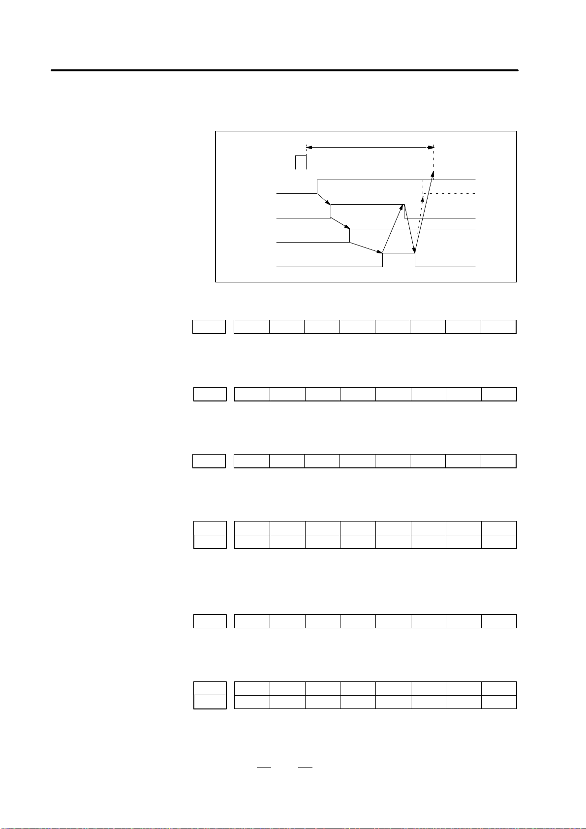
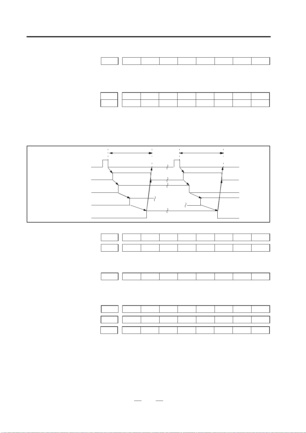
Read auxiliary
function
Auxiliary function code
(BCD)
Strobe (MF, SF,..)
Operation of function
Completion (FIN)
DGN 700.0=1
To the next block
S
and T
functions
M function
#7 #6 #5 #4 #3
TF
#2
SF
#1 #0
MF
0150
DGN
Strobe signals
#7 #6 #5
MF3
#4
MF2
#3 #2 #1 #0
0157
DGN
MF2, MF3 Strobe signal for multiple M functions per block
#7 #6 #5 #4 #3
FIN
#2 #1 #0
0120
DGN
FIN Auxiliary function completion (common to M, S, T and B)
#7
M28
#6
M24
#5
M22
#4
M21
#3
M18
M38
#2
M14
M34
#1
M12
M32
#0
M11
M31
0151
DGN
0157
DGN
– M31 to M38 are the BCD code corresponding to the third digit with the
3–digit M function.
#7
S28
#6
S24
#5
S22
#4
S21
#3
S18
#2
S14
#1
S12
#0
S11
0152
DGN
– This signal is not used for the 4–digit S function.
#7
T28
T48
#6
T24
T44
#5
T22
T42
#4
T21
T41
#3
T18
T38
#2
T14
T34
#1
T12
T32
#0
T11
T31
0153
DGN
0156
DGN
– T31 to T48 are the BCD code corresponding to the fourth and third
digits with the 4–digit T function.
[Ordinary interface]
D Operation sequence of
auxiliary functions
[M function]
[2–digit S function only]
[T function]
1. DISPLA Y AND OPERATION OF CRT/MDI
B–62545EN/02
10
#7
BF1
#6
BF2
#5 #4 #3 #2 #1 #0
0150
DGN
BF1 Strobe signal for the 3 low–order digits of the B code
BF2 Strobe signal for the 3 high–order digits of the B code
#7
B28
#6
B24
#5
B22
#4
B21
#3
B38
B18
#2
B34
B14
#1
B32
B12
#0
B31
B11
0154
DGN
0155
DGN
– For the 6–digit B function, code signals are output for every three digits.
DGN 700.0=1 DGN 700.0=1
To the next block To the next block
Read auxiliary function
Auxiliary function code (BCD)
Strobe (MF, SF ,..)
Behavior of function
Completion (MFIN,...)
#7
BF1
#6
BF2
#5 #4 #3
TF
#2
SF
#1 #0
MF
0150
DGN
BFIN1 BFIN2 TFIN SFIN MFIN0115
DGN
MFIN, SFIN, TFIN Function completion signals
#7 #6 #5
CRST
#4 #3 #2 #1 #0
0701
DGN
#5 CRST The emergency stop signal (*ESP), external reset signal (ERS), reset &
rewind signal (RRW), or MDI reset button is on.
#7 #6 #5 #4
*ESP
#3 #2 #1 #0
0021
DGN
ERS *ESP0121
DGN
RRW0104
DGN
*ESP 0 : The emergency stop signal is on.
ERS 1 : The external reset signal is on.
RRW 1 : The reset & rewind signal is on.
– There is no DGNOS display for the MDI reset button.
[3–/6–digit B function]
[High–speed interface]
D Auxiliary–function
operation sequences
B–62545EN/02
1. DISPLA Y AND OPERATION OF CRT/MDI
11
#7
STP#6REST#5EMS#4RRW#3RSTB
#2 #1 #0
CSU
0712
DGN
This diagnosis information is valid only if automatic operation is
terminated when it should not be. The information indicates the reason
why the cycle start lamp (STL) is off.
#7 #6 #5 #4 #3 #2 #1 #0 Reason
1 1 1 0 0 0 0 1 The emergency stop signal (*ESP) was input.
1 1 0 0 0 0 0 0 The external reset (ERS) signal was input.
1 1 0 1 0 0 0 0 The reset & rewind (RRW) signal was input.
1 1 0 0 1 0 0 0 The MDI reset button was pressed.
1 0 0 0 0 0 0 1 A servo alarm occurred.
1 0 0 0 0 0 0 0 The feed hold (*SP) signal was input, or
another manual mode was selected.
0 0 0 0 0 0 0 0 The machine stopped in a single–function
block.
. All these bits are cleared to 0 when the power is switched on.
#7 #6 #5 #4
*ESP
#3 #2 #1 #0
0021
DGN
ERS *SP *ESP0121
DGN
*ESP 0 The emergency stop signal is on.
ERS 1 The external reset signal is on.
*SP 0 The feed hold signal is on.
#7 #6
RRW
#5 #4 #3 #2 #1 #0
0104
DGN
RRW 1 The reset & rewind signal is on.
#7 #6 #5 #4 #3 #2 #1
SBK
#0
0116
DGN
SBK 1 : The single block signal is on.
#7 #6 #5 #4 #3 #2
MD4#1MD2#0MD1
0122
DGN
Automatic operation (AUTO) 0 0 1
Manual data input (MDI) 0 0 0
– If the program ends with M02 or M03, the machine may enter state 1
or 2 in the above table depending on the processing adopted by the
machine tool builder.
*(1)
*(2)

1. DISPLA Y AND OPERATION OF CRT/MDI
B–62545EN/02
12
[ ABS ] [ REL ] [ ALL ] [ HNDL ] [ ]
ACTUAL POSITION (ABSOLUTE)
ACT.F 3000 MM/M S 0 T
NOT READY ALM BAT BUF AUTO
O0010 N0000
X 123.456
Y 363.233
Z 0.000
MDI Manual data input
AUTO Automatic operation (memory– or tape–based operation)
EDIT Memory editing
HNDL Manual handle feed
JOG Jog feed
TJOG Teach–in jog feed
THND Teach–in handle feed
STEP Manual incremental feed
ZRN Manual reference position return
Alarm Indicates the current alarm.
BAT Indicates that the battery voltage is dropping.
Input Indicates that data is being input.
Output Indicates that data is being output.
Search Indicates that a search is being carried out.
Editing Indicates that some other miscellaneous editing operation
(such as insertion or modification) is under way.
Collation Indicates that a program is being collated.
LSK Indicates the state of label skipping during data input.
BUF Indicates that the next block to be executed has been read.
NOT READY Indicates that the machine is in the emergency stop
state.
1.4
NC STATUS DISPLAYS
(1)Current mode
(2) Alarm conditions
(3) Other status displays
B–62545EN/02
1. DISPLA Y AND OPERATION OF CRT/MDI
13
Reset
Function
Data
protec-
tion
key
Param-
eter
write=1
Mode
Func-
tion
button
Operation
Resetting run hour
–
POS
→
R
CAN
Resetting no. of
machined parts
–
POS
→
P
CAN
Resetting OT alarm
At Pow-
er ON
–
and
P
CAN
Resetting alarm 100
–
– CAN
and
RESET
Registration from MDI
Function
Data
protec-
tion
key
Param-
eter
write=1
Mode
Func-
tion
button
Operation
Inputting
parameters
f MDI
(PARAM)
SYSTEM
Parameter no.→[NO.SRH]→Data→
→ PWE =0 →
INPUT
RESET
Inputting offset
values
–
OFFSET
Offset number→[NO.SRH]→Offset value→
INPUT
Inputting setting
data
MDI
OFFSET
SETTING
Setting no.→[NO.SRH]Data→
INPUT
Input of PMC
parameters
f f MDI
(DGNOS)
SYSTEM
Setting no.→→→Data→
INPUTINPUT
DGNOS
PARAM
Registration from tape
Function
Data
protec-
tion
key
Param-
eter
write=1
Mode
Func-
tion
button
Operation
Inputting
parameters
(tape→memory)
f EDIT
(DGNOS)
SYSTEM
INPUT
Input of PMC
parameter
f f EDIT
(DGNOS)
SYSTEM
INPUT
Inputting offset
values
EDIT
OFFSET
INPUT
Registration of
program
f
EDIT/
AUTO
PRGRM
INPUT
1.5
LIST OF OPERATIONS
1. DISPLA Y AND OPERATION OF CRT/MDI
B–62545EN/02
14
Punch out
Function
Data
protec-
tion
key
Param-
eter
write=1
Mode
Func-
tion
button
Operation
Punch of parameter EDIT
(PARAM)
SYSTEM
OUTPUT
Punch of PMC
parameter
EDIT
(DGNOS)
SYSTEM
OUTPUT
Punch of offset EDIT
OFFSET
SETTING
OUTPUT
Punch of all
programs
EDIT
PROG
→ –999 →
O
OUTPUT
Punch of one
program
EDIT
PROG
→Program no.→
O
OUTPUT
Search
Function
Data
protec-
tion
key
Param-
eter
write=1
Mode
Func-
tion
button
Operation
Searching a
program number
EDIT/
AUTO
PROG
→Program no.→ (cursor key)
O
Searching a
sequence number
AUTO
PROG
Program no. search→→Sequence number
→ (cursor key)
N
Searching an
address word
EDIT
PROG
Data to be searched→ (cursor key)
Searching an
address only
EDIT
PROG
Address to be searched→ (cursor key)
Searching an offset
number
–
OFFSET
SETTING
→Offset no.→
INPUT
NO.
Searching a
diagnostic number
–
(DGNOS)
SYSTEM
→Diagnostic number→
INPUT
NO.
Searching a
parameter number
–
(PARAM)
SYSTEM
→Parameter no.→
INPUT
NO.

B–62545EN/02
1. DISPLA Y AND OPERATION OF CRT/MDI
15
Edit
Function
Data
protec-
tion
key
Param-
eter
write=1
Mode
Func-
tion
button
Operation
Display of memory
capacity used
EDIT
PROG
PRGRM
Deleting all
programs
f EDIT
PROG
→–9999→
O
DELETE
Deleting a program f EDIT
PROG
→Program no.→
O
DELETE
Deleting several
blocks
f EDIT
PROG
→Sequence no.→
N
DELETE
Deleting a block f EDIT
PROG
→
EOB
DELETE
Deleting a word f EDIT
PROG
Searching a word to be deleted→
DELETE
Changing a word f EDIT
PROG
Searching a word to be changed→New Data→
ALTER
Inserting a word f EDIT
PROG
Searching a word immediately before a word to be
searched→New Data→
INSERT
Collation
Function
Data
protec-
tion
key
Param-
eter
write=1
Mode
Func-
tion
button
Operation
Collating memory EDIT
PROG
INPUT
Input/Output with FANUC Cassette
Function
Data
protec-
tion
key
Param-
eter
write=1
Mode
Func-
tion
button
Operation
Registeration of
program
f
EDIT/
AUTO
PROG
→File no.→→
N
INPUT INPUT
Output of all
program
EDIT
PROG
→–9999→
O
OUTPUT
Output of
a program
EDIT
PROG
→Program no.→
O
OUTPUT
Heading a file
EDIT/
AUTO
PROG
→File no.→
N
INPUT
Deleting a file f EDIT
PROG
→File no.→
N
OUTPUT
Collating a program
EDIT/
AUTO
PROG
→File no.→→
N
INPUT INPUT

1. DISPLA Y AND OPERATION OF CRT/MDI
B–62545EN/02
16
Clear
Function
Data
prote-
ction
key
Param-
eter
write=1
Mode
Func-
tion
key
Operation
Memory all clear At
power
ON
AND
RESET DELETE
Parameter clear
f
At
Power
ON
RESET
Clearing a program
f
At
Power
ON
DELETE

B–62545EN/02
2. HARDWARE
17
2
HARDW ARE
This chapter describes structure of CNC control section, connection of
units and the functions of PCBs and modules mounted on PCBs.
2.1 CONTROL UNIT 18. . . . . . . . . . . . . . . . . . . . . . . . . . . . .
2.2 COMPLETE CONNECTION DIAGRAM 19. . . . . . . . . .
2.3 INTER–MACHINE CONNECTION 25. . . . . . . . . . . . . .
2.4 LEDS ON PRINTED–CIRCUIT BOARDS 56. . . . . . . . .
2.5 PRINTED–CIRCUIT BOARD UNIT LIST 57. . . . . . . . .
2.6 BATTERY REPLACEMENT METHOD 62. . . . . . . . . . .
2.7 DETAILS OF POWER SUPPLY 64. . . . . . . . . . . . . . . . . .
2.8 MAINTENANCE OF HEAT PIPE TYPE
HEAT EXCHANGER 78. . . . . . . . . . . . . . . . . . . . . . . . . .

2. HARDWARE
B–62545EN/02
18
Each control P.C.B. of Series 0–D is mounted in the slot as follows.
Available series is in parenthesis.
MEM slot
I/O slot
AXE slot
PMC slot
Power
supply
unit
Memory
card
Internal
I/O card
C6 (TD,
GCD)
C7 (all)
E2 (TD)
E3 (TD, MD)
1st to 4th
card
Type–A
(TD, MD)
Type–B
(All)
PMC–M
Package
3 of TD
and MD
can use
Power
supply unit
AI (All)
CE marking
AI (TD, MD)
NOTE
Connection position of this figure are depended on each printed board.
2.1
CONTROL UNIT
2.1.1
Configuration of the
Control Unit

B–62545EN/02
2. HARDWARE
19
The complete connection diagram shows examples of connecting all PC
boards that can fit into the slots of the master PC board. Some slots can
accept two or more PC boards which are connected to different devices.
This drawing shows two or more identical slot names, but actual
individual slots on the master PC board have different names. See the
connection of each slot according to the PC board to be fitted into the slot.
The diagram shows the connection of all PC boards that can be fitted into
the slots. In the actual unit, the PC boards to be mounted are determined
by the model and optional functions. Note that all the PC boards shown
in the diagram are not always mounted.
2.2
COMPLETE CONNECTION DIAGRAM
2.2.1
Precautions

2. HARDWARE
B–62545EN/02
20
CAP
Power supply
unit AI
CP1
CP2
CP2
CP3
CP14
CP15
BK3.F
BK3.F
BK3.F
BWG6.F
BN3.F
BN6.F
H50.F
H20.F
H50.F
H50.F
H50.F
I/O C6–C7
M1
M2
M18
M19
M20
C6
C7
I/O
CAP
(Continued)
Servo magnetic
contactor
ON/OFF switch
Single–phase 200–VAC
input
200–V AC output
(spare)
24–VDC output
24–VDC output
(display unit using 24 VDC)
H50.M
H50.M
H50.M
H20.M
H50.M
Power magnetics cabinet
MasterPC board
(spare)
For CE marking power
supply
unit AI
CP1
CP3
CP2
CP4
CP6
CP5
AHX3.F
AHX3.F
AHX3.F
AL Y6.F
ALX3.F
AL Y3.F
Servo magnetic
contactor
ON/OFF switch
Single–phase 200–VAC
input
200–V AC output
(spare)
24–VDC output
24–VDC output
(spare)
H50.F
H20.F
H50.F
H50.F
H50.F
I/O E2, E3
M201
M202
M218
M219
M220
E2
E3
I/O
H50.M
H50.M
H50.M
H20.M
H50.M
Power magnetics cabinet
(display unit using 24 VDC)

B–62545EN/02
2. HARDWARE
21
COP5
M5
(Continued)
H20.M
Memory card
D25.F
Relay connector
RS–232–C I/O unit (channel 0, channel 1)
Manual pulse generator
(first unit)
H20.M
M26
H20.F
H20.F
Spindle control
circuit
(analog control)
Spindle motor
S analog output (analog spindle)
Spindle
Position
coder
H20.F
M27
M12
CN11A Spindle control
circuit (Digital control)
CN11B First unit
S serial output (serial spindle)
OPT OPT
OPT
CN11A Spindle control
circuit (Digital control)
CN11B Second unit
OPT
Battery for memory
backup
BWG3.F
CPA7
(For memory PC board)
Spindle motor
Spindle
Position
coder
Spindle motor
Spindle
Position
coder
H20.F
H20.F
CCX5
M3
MEM
CN1 Display (CRT)
KM1 MDI unit
H20.M
H20.F

2. HARDWARE
B–62545EN/02
22
(Continued)
1st to 4th axis
control
CN1 Servo amplifier
(Digital control)
First axis
H20.M
H20.F
M184
AXE
AC
servo motor
H20.F
M185
(Command)
(Velocity/position feedback) Serial pulse coder
A/B–phase pulse coder
(Servo system of semi–closed loop)
CN1 Servo amplifier
(Digital control)
First axis
H20.M
H20.F
M184
AC
servo motor
H20.F
M186
(Command)
(Velocity feedback)
Servo system of closed loop
H20.F
M185
(Position feedback)
Linear scale,
separate pulse coder
H20.M
M187
H20.F
M188
H20.F
M189
Second–axis servo amplifier, motor, pulse
coder, scale
(Same as the connection of the first axis)
H20.M
M194
H20.F
M195
H20.F
M196
Third–axis servo amplifier, motor, pulse coder,
scale
(Same as the connection of the first axis)
H20.M
M197
H20.F
M198
H20.F
M199
Fourth–axis servo amplifier, motor, pulse coder,
scale
(Same as the connection of the first axis)
BWG3.F
CPA9
Battery for absolute pulse coder (for first to
fourth axes)
(Continued)
Serial pulse coder
A/B–phase pulse coder

B–62545EN/02
2. HARDWARE
23
(Continued)
1st to 4th axis
control
JS1B Servo amplifier
(Digital control)
First axis
HF20.F
HF20.F
JS1A
AXE
AC
servo motor
HF20.F
(Command)
(Velocity/position
feedback)
Serial pulse coder
(Servo system of semi–closed loop)
JS1B Servo amplifier
(Digital control)
First axis
H20.M
H20.F
AC
servo motor
H20.F
M186
(Command)
(Velocity feedback)
Servo system of closed loop
(Position feedback)
Linear scale,
separate pulse coder
HF20.F
JS2A
H20.F
M189
Second–axis servo amplifier, motor, pulse
coder, scale
(Same as the connection of the first axis)
HF20.F
JS3A
H20.F
M196
Third–axis servo amplifier, motor, pulse coder,
scale
(Same as the connection of the first axis)
HF20.F
JS4A
H20.F
M199
Fourth–axis servo amplifier, motor, pulse coder,
scale
(Same as the connection of the first axis)
BWG3.F
CPA9
Battery for remote type absolute pulse coder
(for first to fourth axes)
(Continued)
Serial pulse coder
(Type B interface control PC board)
JF1
JS1A
JF1

2. HARDWARE
B–62545EN/02
24
(Continued)
PMC–M
*Both Package 3 of 0–TD and 0–MD can use only.
PMC

B–62545EN/02
2. HARDWARE
25
1 RVDO
2 HSYN
3 VSYN
4 GVDO
11 0V
12 0V
13
14
5 BVDO
6
7
8 0V
15
16
17
18
9 0V
10 0V
19
20
Control unit
Memory card CCX5
(MR–20RMD)
1 RVDO
2 HSYN
3 VSYN
4 GVDO
0V
0V
5 BVDO
6
7
8 0V
9 0V
10 0V
RVDO
1
2
3
4
1
8
4
11
RVDO
0V
GVDO
0V
Maximum cable length: 50 m
Recommended cable material : A66L–0001–0219 coaxial cable
Recommended cable order number: A02B–0098–K825 (7 m)
CRT unit
CN1
(MR–20RM)
H20.F H20.F
Cable wiring
0V
GVDO
0V
BVDO
5
6
18
14
5
12
2
9
BVDO
0V
HSYNC
0V
0V
HSYNC
0V
12
16
3
10
VSYNC
0V
0V
VSYNC
11
12
13
14
15
16
17
18
19
20
2.3
INTER–MACHINE
CONNECTION
2.3.1
CRT/MDI Unit
D Video signal interface

2. HARDWARE
B–62545EN/02
26
Use a power cable containing conductors of 30/0.18 (0.8 mm2) or greater .
(1) 9″ monochrome CRT
1
2
3 0V
4 0V
5 +24V
6 +24V
Power supply unit
CP15 (SMS6RN–4)
9″ CRT unit
(monochrome)
CN2 (SMS6RN–4)
Cable side connector (CP15)
Housing: Japan Burndy SMS6PN–5
Contact: Japan Burndy RC16M–23T3 or
RC16M–SCT3
J38
1
2
3 0V
4 0V
5 +24V
6 +24V
Recommended cable: A02B–0072–K814 (7 m)
1 +24V
2 0V
3
For CE marking
Power supply unit
CP15 (SMS6RN–4)
9″ CRT unit
(monochrome)
CN2 (SMS6RN–4)
Cable side connector (CP15)
Housing: Japan Burndy SMS6PN–5
Contact: Japan Burndy RC16M–23T3 or
RC16M–SCT3
J38
1
2
3 0V
4 0V
5 +24V
6 +24V
Recommended cable: A02B–0120–K820 (5 m)
Cable side connector (CP5)
Housing: JAPAN AMP 2–178288–3
Contact: JAPAN AMP 1–175218–5
Some separate display units have soft keys. These units have flat cables
for the soft keys. Connect the soft key cable to connector KM2 of a
separate MDI unit.
KM2
Separate display unit
Separate MDI unit
The flat cable is about 500 mm long.
D Connecting the display
unit power supply
D Connecting the soft key
cable of a separate
display unit

B–62545EN/02
2. HARDWARE
27
1 *KCM08
2 *KCM00
3 *KCM01
4 *SW06
11 *SW05
12 *SW03
13 *SW01
14 *KCM04
5 *SW04
6 *SW02
7 *SW00
8 *KCM02
15 *KCM05
16 *KCM06
17 *KCM07
18
9 *KCM03
10 *SW07
19
20
Control unit
Memory card M3
(MR–20RMD) (MR–20RFM)
*KCM08
(01)
(02)
(03)
(04)
Use unified shield cable and the length is 50m or less.
Recommended cable : A02B–0050–K803 (7m) or A02B–0098–K803 (7m)
Recommended cable material : A66L–0001–0041 (7/0. 18, 20 core)
MDI unit
KM1
H20.F H20.M
Cable connection
*SW06
*KCM01
*KCM00
*SW04
(05)
(06)
(07)
(08)
*KCM02
*SW00
*SW02
(09)
(10)
*SW07
*KCM03
(11)
*SW05
*SW03
(12)
(13)
(14)
(15)
*KCM05
*KCM04
*SW01
(16)
(17)
*KCM07
*KCM06
Shield
1 *KCM08
2 *KCM00
3 *KCM01
4 *SW06
11 *SW05
12 *SW03
13 *SW01
14 *KCM04
5 *SW04
6 *SW02
7 *SW00
8 *KCM02
15 *KCM05
16 *KCM06
17 *KCM07
18
9 *KCM03
10 *SW07
19
20
*KCM08
*SW06
*KCM01
*KCM00
*SW04
*KCM02
*SW00
*SW02
*SW07
*KCM03
*SW05
*SW03
*KCM05
*KCM04
*SW01
*KCM07
*KCM06
(01)
(02)
(03)
(04)
(05)
(06)
(07)
(08)
(09)
(10)
(11)
(12)
(13)
(14)
(15)
(16)
(17)
D Connection to MDI unit
MDI unit interface

2. HARDWARE
B–62545EN/02
28
1
FG SD RD RS CS DR SG CD
2 3 4 5 6 7 8 9 10 11 12 13
14 15 16 17 18 19 20 21 22 23 24 25
ER +24V
Interconnection connector signal arrangement
CNC
FG
Interconnection
cable
Interconnection connector
Connector: DBM–25S (Japan Aviation Electronics)
Lock hardware: D20418–J2 (Japan Aviation Electronics)
Cable–end connector
Connector: DBM–25P
(Japan Aviation Electronics)
Lock hardware: DB–C2–J9
(Japan Aviation Electronics)
Control unit
M5 (MR–20RFD)
1
2
3
4
11
12
13
14 +24V
5 ER
6
7
8 RD
15
16 CD
17 SG
18 DR
9 SD
10
19 CS
20 RS
CAUTION
1 The machine tool builder is requested to provide the
interconnection connectors and cables.
2 Use a common shielded cable for the signal cable.
Recommended cable specification: A66L–0001–0041
2.3.2
Reader/Puncher Interface

B–62545EN/02
2. HARDWARE
29
Control unit
M12 Honda Tsushin MR–20RMD
1 0V
2 0V
3 0V
4 +5V
11
12
13
14
5 +5V
6 +5V
7
8 HA1
15
16
17
18
9 HB1
10
19
20
3
+5V4+0V5HA16HB1
M3 screw terminal
Manual pulse generator (for the first axis)
J24
Cable: Cable with common shielded conductors, 7/0.18 (0.2 mm2) or thicker
Recommended cable conductor specification: A66L–001–0041
A02B–0050–K802 (7 m) is usable for J24.
Honda Tsushin
Manual pulse generator
(for the first axis)
HA1
+5V
M12(6)
M12(1)
M12(2)
M12(3)
M12(8)
M12(9)
M12(5)
M12(4)
HB1
Control unit
+5V
2
3
0V
HA1
4
5
HB1 6
Similarly to the pulse coder, the manual pulse generator is designed to
operate on 5 VDC. So, any voltage drop relative to the supply voltage
must be kept to within 0.2 V (total drop through the 0 V and 5 V lines).
Namely:
0.2 y
0.1 R 2L
m
where 0.1 : Current required by the manual pulse generator
R : Wire resistance per unit length [Ω/m]
m : Number of wires in the 0 V or 5 V cable
L : Cable length [m]
Thus,
L x
m
R
2.3.3
Manual pulse Generator
Manual pulse generator
cable

2. HARDWARE
B–62545EN/02
30
This section describes the servo interface between the Series 0–D and the
a and b series servo amplifier and servo motor.
The Series 0–D supports two types of axis control cards according to the
type of servo interface.
D Axis control card of type A interface
(It can be used by 0–TD and 0–MD)
D Axis control card of type B interface
Axis control card of type A interface Axis control card of type B interface
Axis name Command
Semi–
closed
loop
Closed loop
Command
Semi–
closed
loop
Closed loop
Feedback
Position
feedback
Velocity
feedback
Feedback
Position
feedback
Velocity
feedback
1st axis M184 M185 M186 M185 JS1A JFn M186 JFn
2nd axis M187 M188 M189 M188 JS2A JFn M189 JFn
3rd axis M194 M195 M196 M195 JS3A JFn M196 JFn
4th axis M197 M198 M199 M198 JS4A JFn M199 JFn
For a type B interface axis control card, the feedback or velocity feedback
cable is connected to the JFn connector on the servo amplifier, where n
varies with the servo amplifier being used.
2.3.4
Servo Interface
D Outline
D Connector names

B–62545EN/02
2. HARDWARE
31
Battery
unit
Pulse
coder
Servo
motor
Servo amplifier
Power
Type A interface axis
control card
Command
Feedback
The battery unit is not required when an incremental pulse coder is used.
(when an absolute pulse coder and relay unit are used)
Battery
unit
Pulse
coder
Servo
motor
Servo amplifier
Power
Type A interface axis
control card
Command
Feedback
Relay
unit
D Semi–closed loop
system
D Semi–closed loop
system

2. HARDWARE
B–62545EN/02
32
Pulse
coder
Servo
motor
Servo amplifier
Power
Type B interface axis
control card
Command/
Feedback
Battery
unit
The battery unit is not required when an incremental pulse coder is used.
Use the servo amp. for type B interface or set common amp. to the B type.
Feedback
Pulse
coder
Servo
motor
Servo amplifier
Power
Type A interface axis
control card
Command
Remote
pulse coder
Battery
unit
The battery unit is not required when an incremental pulse coder is used.
Velocity feedback
Position feedback
D Semi–closed loop
system
D Closed loop system

B–62545EN/02
2. HARDWARE
33
(when an absolute pulse coder and relay unit are used)
Pulse
coder
Servo
motor
Servo amplifier
CN1
Power
Series 0 axis control
card
Command
Velocity feedback
Remote
pulse coder
Battery
unit
Relay
unit
Position feedback
Pulse
coder
Servo
motor
Servo amplifier
CN1
Power
Type B interface axis
control card
Command/
Velocity feedback
Remote
pulse coder
Battery
unit
Position feedback
Velocity feedback
The battery unit is not required when an incremental remote pulse coder is used.
D Closed loop system
D Closed loop system

2. HARDWARE
B–62545EN/02
34
(1) Servo amplifier interface
This section describes each servo amplifier interface, taking that for
the first axis as an example.
(1)–1 In case of type A interface
01
02
03
04
05
06
07
*PWMAn
COMAn
*PWMBn
COMBn
*PWMCn
COMCn
*DRDYn
08
09
10
11
12
13
IRn
GDRn
ISn
GDSn
*MCONn
GNDn
14
15
16
17
18
19
20
*PWMDn
COMDn
*PWMEn
COMEn
*PWMFn
COMFn
Type A interface axis
control card M184
(MR–20RF)
01
02
03
04
05
06
07
08
09
10
IRn
GDRn
*PWMAn
COMAn
*PWMBn
COMBn
*PWMCn
COMCn
*MCONn
Servo amplifier JV1B (L–axis),
JV2B (M–axis)
CN1
n: axis number
Connector: MR–20LMH (HONDA, 20–pin, male) Connector: PCR–E20FA (HONDA, 20–pin,
half–pitch) or equivalent
Cable connection
IRn
GDRn
*PWMAn
COMAn
*PWMBn
COMBn
*PWMCn
COMCn
*MCONn
ISn
GDSn
*PWMDn
COMDn
*PWMEn
COMEn
*PWMFn
COMFn
*DRDYn
8
9
1
2
3
4
5
6
12
10
11
14
15
16
17
18
19
7
1
2
3
4
5
6
7
8
10
11
12
13
14
15
16
17
18
20
IRn
GDRn
*PWMAn
COMAn
*PWMBn
COMBn
*PWMCn
COMCn
*MCONn
ISn
GDSn
*PWMDn
COMDn
*PWMEn
COMEn
*PWMFn
COMFn
*DRDYn
Shield
Recommended cable material A66L–0001–0284#10P (#28AWG 10pairs)
Recommended cable specification A02B–0098–K841 (5m)
11
12
13
14
15
16
17
18
19
20
ISn
GDSn
*PWMDn
COMDn
*PWMEn
COMEn
*PWMFn
COMFn
*DRDYn

B–62545EN/02
2. HARDWARE
35
CAUTION
T o protect the signals from external noise, assign the cable’s
central pairs to each pair of current feedback signal and
ground signal (i.e., IRn and GDRn, and ISn and GDSn).
Otherwise, external noise may result in uneven feed or
abnormal sound.
For connection on control motor amplifier α series or β series,
refer to the Descriptions manual.

2. HARDWARE
B–62545EN/02
36
(1)–2 Interface to the servo amplifier
:MCONn
GDRn
01
03
IRn
02
:PWMAn
:PWMCn
04
06
0V
05
0V
:PWMEn
08
07
0V
:MCONn
09
:DRDYn
10
GDSn
11
13
ISn
12
:ENBLn
PDn
14
16
0V
15
:PDn
PREQn
18
17
:PREQn
0V
19
0V
20
Servo Amplifier Module
Type B interface axis control card
JS1A (PCR–EV20MDT)
JS1B (L axis) JS2B (M axis)
JS3B (N axis) (PCR–EV20MDT)
01
03
02
04
06
05
08
07
09
10
11
13
12
14
16
15
18
17
19
20
GDRn
IRn
:PWMAn
:PWMCn
0V
0V
:PWMEn
0V
:DRDYn
GDSn
ISn
:ENBLn
PDn
0V
:PDn
PREQn
:PREQn
0V
0V
Connector: PCR–E20FA etc.
(HONDA 20 pin half pitch)
1
2
3
4
5
6
7
8
9
10
11
12
13
14
15
16
17
18
19
20
Shield
IRn
GDRn
:PWMAn
0V
:PWMCn
0V
:PWMEn
0V
:DRDYn
:MCONn
ISn
GDSn
:ENBLn
0V
PDn
:PDn
PREQn
:PREQn
0V
0V
1
2
3
4
5
6
7
8
9
10
11
12
13
14
15
16
17
18
19
20
IRn
GDRn
:PWMAn
0V
:PWMCn
0V
:PWMEn
0V
:DRDYn
:MCONn
ISn
GDSn
:ENBLn
0V
PDn
:PDn
PREQn
:PREQn
0V
0V
CABLE WIRING
RECOMMENDED CABLE MATERIAL A66L–0001–0284#10P(#28WAG 10 pair)
RECOMMENDED CABLE SPECIFICATION A02B–0120–K800(5m)
NOTE
1 The total length of the cable between the CNC and amplifier and that between the amplifier and
motor shall not exceed 50m.
2 As the current feedback lines (IRn and ISn), use the middle twisted pair of the recommended
cable. If any other pair is used, abnormal noise or oscillation may occur.
3 Use a servo unit which supports the type–B interface. When using a servo unit which supports
both the type–A and type–B interfaces, select the type–B interface. For details, refer to the
manual supplied with the servo unit. If the interface setting is incorrect, a servo alarm (AL401
V READY OFF) will be issued.

B–62545EN/02
2. HARDWARE
37
(2) Internal type pulse coder (Serial pulse coder interface)
The connector to which the feedback cable from the built–in pulse
coder is connected varies with the servo interface type.
For the type A interface, connect the feedback cable to the feedback
connector on the axis control card (for example, M185 for the first
axis).
For the type B interface, connect the feedback cable to the feedback
connector on the servo amplifier (for example, JF1 for the first axis).
(2)±1 α series motor (α3/3000 to α150/2000)
A
D
G
K
N
S
V
01
02
03
04
05
06
07
REQ
*REQ
SD
*SD
08
09
10
11
12
13
14
15
16
17
18
19
20
0V
0V
0VB
+5V
+5V
+5V
+6VB
Series 0–D (control unit)
Type A interface axis control card
M185
(MR–20RM)
SD
*SD
*REQn
+5V
0V
0VB
C
F
J
M
R
U
REQ
+5V
+6VB
Pulse coder
(MS3102A–22–29P)
Connector: MR–20LFH (HONDA, 20–pin, female) Connector: MS3106A20–29SW or
MS3108B20–29SW
Cable connection
SD
*SD
REQ
*REQ
+5V
+5V
+5V
0V
0V
0V
+6VB
(16)
(17)
(14)
(15)
(04)
(05)
(06)
(01)
(02)
(03)
(07)
(A)
(D)
(F)
(G)
(J)
(K)
(N)
(T)
(S)
(R)
(H)
Shield
B
E
H
L
P
T
SHILD
0V
SD
*SD
REQ
*REQ
+5V
+5V
0V
0V
0VB
+6VB
SHLD
Cable material: +5V, 0V
Two or more wires each having a cross–sectional area of at least 0.5 mm
2
(when the cable length is 14 m or less)
: +6VB, 0VB One or more wires each having a cross–sectional area of at least 0.5 mm
2
: SD, *SD, REQ, *REQ Twisted pair wires each having a cross–sectional area of at least 0.18 mm
2
J23n
These wires do not have to be connected for
an incremental pulse coder.
NOTE
The voltage resistance for +5 V must not exceed 0.5Ω, total for both ways.

2. HARDWARE
B–62545EN/02
38
(2)±2 α series motor (α1/3000, α2/2000, or α2/3000)
01
02
03
04
05
06
07
REQ
*REQ
SD
*SD
08
09
10
11
12
13
14
15
16
17
18
19
20
0V
0V
0V
+5V
+5V
+5V
+6VB
Series 0–D (control unit)
Type A interface axis control card
M185
(MR–20RM)
Pulse coder
Connector: MR–20LFH (HONDA, 20–pin, female) Connector: HDAB–15S (Hirose Electric, D–SUB)
Connector cover: HDAW–15–CV (Hirose Electric)
Cable connection
SD
*SD
REQ
*REQ
+5V
+5V
+5V
0V
0V
0V
+6VB
(16)
(17)
(14)
(15)
(04)
(05)
(06)
(01)
(02)
(03)
(07)
(12)
(13)
(5)
(6)
(8)
(15)
(1)
(2)
(3)
(10)
(14)
(4)
Shield
SD
*SD
REQ
*REQ
+5V
+5V
0V
0V
0V
0VB
+6VB
SHLD
Cable material: +5V, 0V
Two or more wires each having a cross–sectional area of at least 0.5 mm
2
(when the cable length is 14 m or less)
: +6VB, 0VB
One or more wires each having a cross–sectional area of at least 0.5 mm
2
: SD, *SD, REQ, *REQ Twisted pair wires each having a cross–sectional area of at least 0.18 mm
2
K22
These wires do not have to be connected for
an incremental pulse coder.
1
2
3
4
5
6
7
8
0V
0V
0V
SHLD
REQ
*REQ
+5V
9
10
11
12
13
14
15
0VB
SD
*SD
+6VB
+5V
NOTE
The voltage resistance for +5 V must not exceed 0.5Ω, total for both ways.

B–62545EN/02
2. HARDWARE
39
(3) Remote type pulse coder
(3)–1 Low–resolution A/B phase separate pulse coder (2000P to
3000P) (Separate incremental pulse coder)
The position feedback cable from the separate pulse coder
must be connected to the position feedback connector on the
axis control card (for example, M186 for the first axis),
regardless of the servo interface type.
01
02
03
04
05
06
07
0V
0V
0V
+5V
+5V
+5V
08
09
10
11
12
13
14
15
16
17
18
19
20
PCZn
*PCZn
PCAn
*PCAn
PCBn
*PCBn
Series 0 (control unit)
M35 or M186
(MR–20RM)
A
D
G
K
N
S
An
*Bn
Cn1
Cn8
G
C
F
J
M
R
U
Bn
*PCZn
Cn4
0V
OHnB
0V
Remote pulse coder
(MS3102A–22–14P)
n: axis number
J23n
Connector: MR–20LFH (HONDA, 20–pin, female) Connector: MS3106B–22–14S or
MS3108B–22–14S
Cable connection
PCZn
*PCZn
PCAn
*PCAn
PCBn
*PCBn
+5V
0V
(14)
(15)
(16)
(17)
(18)
(19)
(04, 05, 06)
(01, 02, 03)
(E)
(F)
(A)
(D)
(C)
(E)
(L, T)
(M, U)
(N)
Shield
B
E
H
L
P
T
*An
PCZn
Cn2
+5V
OHnA
+5V
Cable material: +5V, 0V
For each, six or more vinyl–coated wires each having a cross–sectional area of 0.2 mm
2
: Others Unified shield twisted pair wires each having a cross–sectional area of at least 0.1 mm
2
PCZn
*PCZn
PCAn
*PCAn
PCBn
*PCBn
+5V
0V
SHLD
NOTE
The total voltage resistance for +5 V and 0 V must not exceed 0.5Ω, total for both ways.

2. HARDWARE
B–62545EN/02
40
(3)–2 Remote pulse coder (Separate absolute pulse coder)
The velocity feedback connection between the motor’s built–in pulse
coder and the Series 0 is the same as that described in Section 9.3.5.
An A/B–phase absolute pulse coder can be connected to the Series 0 in
either of two ways: via the relay unit of the absolute pulse coder battery
unit, or directly.
D When using the relay unit
(a) Connection between Series 0 and relay unit
01
02
03
04
05
06
07
0V
0V
0V
+5V
+5V
+5V
08
09
10
11
12
13
14
15
16
17
18
19
20
PCZn
*PCZn
PCAn
*PCAn
PCBn
*PCBn
REQn
Series 0 (control unit)
M186
(MR–20RM)
Relay unit
CF1A
(MR–20RM)
Connector: MR–20LFH (HONDA, 20–pin, female)
Cable connection
PCZn
*PCZn
PCAn
*PCAn
PCBn
*PCBn
REQn
+5V
0V
(14)
(15)
(16)
(17)
(18)
(19)
(20)
(04, 05, 06)
(01, 02, 03)
Shield
The cable length must not exceed 2 m.
Recommended cable specification A02B–0074–K804 (2m)
PCZn
*PCZn
PCAn
*PCAn
PCBn
*PCBn
REQn
+5V
0V
Cable material: +5V, 0V
Six or more vinyl–coated wires each having a cross–sectional area of 0.5 mm
2
: Cn1 to Cn8 Vinyl–coated wires each having a cross–sectional area of at least 0.18 mm
2
: Others Unified shield twisted pair wires each having a cross–sectional area of at least 0.18 mm
2
01
02
03
04
05
06
07
0V
0V
0V
+5V
+5V
+5V
08
09
10
11
12
13
14
15
16
17
18
19
20
PCZn
*PCZn
PCAn
*PCAn
PCBn
*PCBn
REQn
Connector: MR–20LFH (HONDA, 20–pin, female)
(14)
(15)
(16)
(17)
(18)
(19)
(20)
(04, 05, 06)
(01, 02, 03)
D Velocity feedback
connection
D Position feedback
connection

B–62545EN/02
2. HARDWARE
41
(b)Connection between relay unit and A/B–phase pulse coder
01
02
03
04
05
06
07
0V
0V
0V
+5V
+5V
+6VA
08
09
10
11
12
13
14
15
16
17
18
19
20
PCZn
*PCZn
PCAn
*PCAn
PCBn
*PCBn
REQn
Relay unit
CF1B
(MR–20RM)
A
D
G
K
N
S
PCAn
*PCBn
SHLD
REQn
C
F
J
M
R
U
PCBn
*PCZn
0V
0V A
A/B–phase separate pulse coder
(separate absolute pulse coder)
(MS3102A–22–14P)
Connector: MR–20LFH (HONDA, 20–pin, female) Connector: MS3106B–22–14S (straight)
MS3108B–22–14S (elbow)
Cable connection
PCZn
*PCZn
PCAn
*PCAn
PCBn
*PCBn
REQn
+5V
0V
+6VA
0V A
(14)
(15)
(16)
(17)
(18)
(19)
(20)
(04, 05)
(01, 02)
(06)
(03)
(E)
(F)
(A)
(B)
(C)
(D)
(S)
(L)
(M)
(T)
(U)
(N)
Shield
B
E
H
L
P
T
*PCAn
PCZn
+5V
+6VA
PCZn
*PCZn
PCAn
*PCAn
PCBn
*PCBn
REQn
+5V
0V
+6VA
0V A
SHLD
Cable material: +5V, 0V
Two 0.5–mm2 wires
: +6VA, 0VA
One 0.5–mm2 wire
: Others
Unified shield twisted pair wires each having a cross–sectional area of 0.18 mm
2
NOTE
The total voltage resistance for +5 V and 0 V must not exceed 0.5Ω, total for both ways,
including the cable between the axis control card and the relay unit.

2. HARDWARE
B–62545EN/02
42
D Direct connection
Cable material : +6VB, 0VB 0.5 mm2 or more
: +5V, 0V 0.5 mm2 or more
: Others Unified shield twisted pair wires each having a cross–sectional area of at least 0.1 mm
2
: REQn 0.18 mm2 or more
01
02
03
04
05
06
07
0V
0V
0VB
+5V
+5V
+5V
+6VB
08
09
10
11
12
13
14
15
16
17
18
19
20
PCZn
*PCZn
PCAn
*PCAn
PCBn
*PCBn
REQn
Series 0 (control unit)
M186
(MR–20RM)
A
D
G
K
N
S
PCAn
*PCBn
SHLD
REQn
C
F
J
M
R
U
PCBn
*PCZn
0V
0VB
A/B–phase separate pulse coder
(separate absolute pulse coder)
(MS3102A–22–14P)
Connector: MR–20LFH (HONDA, 20–pin, female) Connector: MS3106B–22–14S (straight)
MS3108B–22–14S (elbow)
Cable connection
REQn
PCZn
*PCZn
PCAn
*PCAn
PCBn
*PCBn
+5V
0V
+6VB
0VB
(20)
(14)
(15)
(16)
(17)
(18)
(19)
(04, 05, 06)
(01, 02)
(07)
(03)
(S)
(E)
(F)
(A)
(B)
(C)
(D)
(L)
(M)
(T)
(U)
(N)
Shield
B
E
H
L
P
T
*PCAn
PCZn
+5V
+6VB
REQn
PCZn
*PCZn
PCAn
*PCAn
PCBn
*PCBn
+5V
0V
+6VB
0VB
SHLD
Recommended cable specification A02B–0096–K801 (14m) (straight)
A02B–0096–K802 (14m) (elbow)
NOTE
The voltage resistance for +5 V must not exceed 0.5Ω, total for both ways.

B–62545EN/02
2. HARDWARE
43
(4) Connection of the battery unit for an absolute pulse coder
The battery unit for an absolute pulse coder can be connected to the
Series 0 in either of two ways: via a relay unit or directly.
(4)–1 Connection Using the Relay Unit
01
+6VB
02 03 04 05 06
0V
Relay unit
CA7
Connector : SMS6PK–5D28 (Japan Burndy)
Battery unit
Cable connection
Relay unit
+6VB
0V
Battery unit
M3
terminal
(1)
(6)
Cable material: Shielded wire each having a cross–sectional area of
at least 0.18 mm
2
Recommended cable specification: A02B–0072–K902 (4m)
+
–
Shield
NOTE
1 A single relay unit can distribute power from the battery to
up to four pulse coders.
2 A single battery unit can supply power to up to six pulse
coders.
3 Replace the battery with a new one once a year.

2. HARDWARE
B–62545EN/02
44
(4)–2 Connection without a Relay Unit
The battery unit can be connected directly to each axis control
card, from which the battery power is distributed to each
pulse coder.
Battery connector name
1st–4th axis control card
1st axis 2nd axis 3rd axis 4th axis
Connector name CPA9
01
+6VB
02
0V
03
Series 0 (control unit)
CP9, CP10, CP11
Connector: SMS3PWS–5(Japan Burndy)
(A02B–0096–K891)
Battery unit
Cable connection
Relay unit
+6VB
0V
Battery unit
M3
terminal
(1)
(2)
Shield
Cable material: Shielded wire each having a cross–sectional area of
at least 0.18 mm
2
+
–
NOTE
1 A single battery unit can supply power to up to six pulse
coders.
2 Replace the battery with a new one once a year.

B–62545EN/02
2. HARDWARE
45
(5) Handling of unused axes (Clamping)
The user can select any of the supported axes as the axes to be
controlled. A cable for a servo amplifier or motor need not be
connected to those axes that are not to be used. Leaving the connector
for an unused axis open, however, causes the CNC to enter a servo
alarm state. This section describes how to handle (clamp) unused
axes.
NOTE
Servo parameters must also be set for clamped axes. Set
the same servo parameters as those for any axis to be used.
(5)–1 Handling of the Command Connectors of Unused Axes
Connect a command clamping dummy connector to the
command connector of each unused axis.
Command clamping dummy connector
MR–20LMH
(HONDA, 20–pin, male)
*DRDYn
*MCONn
(7)
(12)
Jumper
Command clamping dummy connector
PCR–E20FA
(HONDA, 20–pin, female)
*DRDYn
*MCONn
(9)
(10)
Jumper
(5)–2 Handling of the Feedback Connectors of Unused Axes
A dummy connector is not necessary . Set the relevant servo
parameters as follows and leave the feedback connectors
open.
Set the axis ignore parameter (bit 0 of No. 8n09: n is the axis
number) for each unused axis to 1. Set flexible feed gear
parameters 8n84 and 8n85 to 1.
D
Type A interface
D Type B interface

2. HARDWARE
B–62545EN/02
46
1 *SIN
2 SIN
3 *SOUT
4 SOUT
0V
0V
0V
0V
5
6
7
8
0V
0V
+5V
9 +5V
10 +5V
1 SIN
2 *SIN
3 SOUT
4 *SOUT
0V
0V
0V
0V
5
6
7
8
0V
0V
+5V
9 +5V
10 +5V
COP
FS0–C
Connector
: PCR–E20FA
(HONDA 20–pin, half pitch)
Housing
: PCR–V20LA
Code of optical cable (K4X)
A66L–6001–0009#LVVVVV
(with reinforced jacket)
Length designation
or A66L–6001–0008#L2R003 (2m) (Without reinforced jacket)
1111
1212
1313
1414
1515
1616
1717
1818
1919
2020
1111
1212
1313
1414
1515
1616
1717
1818
1919
2020
Memory card
COP5
or
5th/6th axis card
COP6
Optical cable
Optical link adapter JD1
Electric cable J39
(up to 2 m)
α–series spindle amplifier module
JA7B
K4X
Shield
0V
*SIN
SIN
*SOUT
SOUT
+5V
+5V
+5V
0V
0V
0V
0V
0V
(16)
(1)
(2)
(3)
(4)
(9)
(18)
(20)
(11)
(12)
(13)
(14)
(15)
(16)
(4)
(3)
(2)
(1)
(9)
(18)
(20)
(11)
(12)
(13)
(14)
(15)
0V
*SOUT
SOUT
*SIN
SIN
+5V
+5V
+5V
0V
0V
0V
0V
0V
Recommended cable material A66L–0001–0284#10P (#28AWG × 10)
Recommended cable specification A02B–0120–K844 (1m)
Electric cable connection J39
2.3.5
Serial Spindle Interface

B–62545EN/02
2. HARDWARE
47
The speed of the analog spindle is specified by analog voltage output. The
analog output for the first spindle can be output from pin 10 of M12 or
pin 7 of M26.
Control unit
M12 (MR–20RMD)
1 (0V)
2 (0V)
3 (0V)
4 (+5V)
11 0V
12
13
5 (+5V)
6 (+5V)
7
8 (HA1)
9 (HB1)
10 SVC
M26 (MR–20RFD)
1
2
3
4
11
12
13
5
6
7 SVC
8
9
10
To spindle control
circuit
To spindle control
circuit
Å
Å
Control unit
SVC
(Spindle speed command)
0V
Ground plate
Cable material 12/0.18 (0.3mm
2
) Unified shield twisted–pair cable
Recommended cable A66L–0001–0041
1414
1515
1616
1717
1818
1919
2020
0V
1414
1515
1616
1717
1818
1919
2020
NOTE
1 M12 is also used as the connector for the first manual pulse
generator.
2 In addition to the spindle speed analog voltage signal
(SVC), use the spindle enable signal (ENB). Use the same
cable as that indicted above.
2.3.6
Analog Spindle Interface

2. HARDWARE
B–62545EN/02
48
Unified shield twisted–pair cable
Characteristic impedance: 100 Ω
*SC
0V
+5V
PA
*PA
PB
*PB
SC
(15)
(1)(2)(3)
(4)(5)(6)
(16)
(17)
(18)
(19)
(14)
(P)
(K)
(H)
(A)
(N)
(C)
(R)
(B)
1 0V
2 0V
3 0V
4 +5V
11
12
13
SC
5 +5V
6 +5V
7
8
*SC
PA
*PA
PB
9
10
*PB
Signal name Description
SC, *SC Position coder phase–C signal
PA, *PA Position coder phase–A signal
PB, *PB Position coder phase–B signal
CNC
*SC
0V
+5V
PA
*PA
PB
*PB
SC
Position coder
M27 MRE20–RMD
Position
coder input
Connector pin number
1414
1515
1616
1717
1818
1919
2020
NOTE
The current drain of the position coder is 0.35 A. Determine
the number of 0V and +5V lines to be connected so that the
total voltage drop between the NC and position coder does
not exceed 0.2 V, total for both ways.
2.3.7
Position Coder Interface

B–62545EN/02
2. HARDWARE
49
The peripheral units, such as the control unit and CRT/MDI, have been
designed on the assumption that they are housed in closed cabinets. In
this manual “cabinet” refers to the following:
D Cabinet manufactured by the machine tool builder for housing the
control unit or peripheral units;
D Cabinet for housing the flexible turnkey system provided by FANUC;
D Operation pendant, manufactured by the machine tool builder, for
housing the CRT/MDI unit or operator’s panel.
D Equivalent to the above.
The environmental conditions when installing these cabinets shall
conform to the following table.
In operation 0_ to 45_
Room temperature
In storage or transportation –20_ to 60_
Change in
temperature
1.1°C/minute max.
Normal 75% or less
Relative humidity
Temporary (within 1 month) 95% or less
Vibration In operation: 0.5G or less
Environment
Normal machine shop environment
(The environment must be considered if the cabinets are in a
location where the density of dust, coolant, and/or organic
solvent is relatively high.)
In operation 0°C to +55°C
Room temperature
In storage or transportation –20°C to +60°C
Relative humidity 95% RH or less (no condensation)
Vibration 0.5 G or less
Environment
The unit shall not be exposed direct to cutting oil, lubricant or
cutting chips.
The power capacity of the CNC control unit, which in this section means
the specification required for the power supply , is obtained by adding the
power capacity of the control section and the power capacity of the servo
section.
The power capacity of the control section includes the power capacity of
the control unit, CRT/MDI.
Power capacity of the
control section
0.4 kVA
Power capacity of the
servo section
Depends on servo motor type.
Refer to each DESCRIPTIONS.
2.3.8
External Environmetal
Requirements of
Cabinet
2.3.9
Installation Condition
of CNC and Servo Unit
2.3.10
Power Capacity

2. HARDWARE
B–62545EN/02
50
The CNC has been steadily reduced in size using surface–mount and
custom LSI technologies for electronic components. The CNC also is
designed to be protected from external noise. However, it is difficult to
measure the level and frequency of noise quantitatively, and noise has
many uncertain factors. Generally, noise is induced in the CNC due to
electrostatic coupling, electromagnetic induction, and ground loop.
The CNC is equipped with provisions to minimize the influence of
extraneous noise. However, it is difficult to quantitatively measure the
strength of the noise and how often it occurs. Besides, noise has many
unknown elements. To maintain the stability of the CNC machine tool
system, it is important to minimize the occurrence of noise and prevent
it from being induced into the CNC.
When designing the power magnetics cabinet, guard against noise in the
machine as described in the following section.
(1) Separationg signal lines
The cables used for the CNC machine tool are classified as listed in the
following table:
Process the cables in each group as described in the action column.
Group Signal line Action
Primary AC power line
Bind the cables in group A separately (Note 1) from groups B and C, or
Secondary AC power line
gp p y( ) gp
cover group A with an electromagnetic shield (Note 2).
A
AC/DC power lines (containing the power lines for
the servo and spindle motors)
See Section (3) and connect spark killers or diodes with the solenoid and
relay.
AC/DC solenoid
AC/DC relay
DC solenoid (24VDC)
Connect diodes with DC solenoid and relay.
DC relay (24VDC)
Bind the cables in group B separately from group A, or cover group B
B
DI/DO cable between the CNC and power magnetics cabinet
with an electromagnetic shield.
Separate group B as far from Group C as possible.
DI/DO cable between the CNC and machine
It is more desirable to cover group B with the shield.
Cable between the CNC and servo amplifier
Bind the cables in group C separately from group A, or cover group C
Cable for position and velocity feedback
gp p y gp gp
with an electromagnetic shield.
Cable between the CNC and spindle amplifier
Separate group C as far from Group B as possible.
Cable for the position coder
Be sure to perform shield processing in Section (4).
C
Cable for the manual pulse generator
Cable between the CNC and the CRT/MDI
RS–232–C interface cable
Cable for the battery
Other cables to be covered with the shield
NOTE
1 The groups must be 10 cm or more apart from one another
when binding the cables in each group.
2 The electromagnetic shield refers to shielding between
groups with grounded steel plates.
2.3.11
Action Against Noise

B–62545EN/02
2. HARDWARE
51
Cable of group B, C
Cable of group A
Cabinet
Spindle
amp.
Servo
amp.
Control
unit
Duct
To operator’s
panel,
motor, etc.
Section
Group A Group B, C
Cover
(2) Ground
The following ground systems are provided for the CNC machine tool:
D Signal ground system (SG)
The signal ground (SG) supplies the reference voltage (0V) of the
electrical signal system.
D Frame ground system (FG)
The frame ground system (FG) is used for safety , and suppressing
external and internal noises. In the frame ground system, the
frames, cases of the units, panels, and shields for the interface
cables between the units are connected.
D System ground system
The system ground system is used to connect the frame ground
systems connected between devices or units with the ground.
Power
magnetics
unit
Servo
amplifier
CNC
control
unit
Power
magnetics
cabinet
Distribution board
Operator’s
panel
Machine
tool
System ground system
Frame ground system
Signal ground system

2. HARDWARE
B–62545EN/02
52
D Connect the signal ground with the frame ground (FG) at only one
place in the CNC control unit.
D The grounding resistance of the system ground shall be 100 ohms
or less (class 3 grounding).
D The system ground cable must have enough cross–sectional area
to safely carry the accidental current flow into the system ground
when an accident such as a short circuit occurs.
(Generally, it must have the cross–sectional area of the AC power
cable or more.)
D Use the cable containing the AC power wire and the system
ground wire so that power is supplied with the ground wire
connected.
Ground cable using
a wire of 2 mm
2
or
greate
Ground strap on
the cabinet
System ground
Control unit (control unit A)
Frame ground
M4 screw for
grounding

B–62545EN/02
2. HARDWARE
53
(3) Noise suppressor
The AC/DC solenoid and relay are used in the power magnetics
cabinet.
A high pulse voltage is caused by coil inductance when these devices
are turned on or off.
This pulse voltage induced through the cable causes the electronic
circuits to be disturbed.
D Use a spark killer consisting of a resistor and capacitor in series. This
type of spark killer is called a CR spark killer.(Use it under AC)
(A varistor is useful in clamping the peak voltage of the pulse
voltage, but cannot suppress the sudden rise of the pulse voltage.
FANUC therefore recommends a CR spark killer.)
D The reference capacitance and resistance of the spark killer shall
conform to the following based on the current (I (A)) and DC
resistance of the stationary coil:
1) Resistance (R) : Equivalent DC resistance of the coil
2) Capacitance (C) :
20
I
2
(mF)
to
I
2
10
I : Current at stationary state of the coil
Equivalent circuit of the spark killer
RC
Spark killer
Spark killer
Motor
AC
relay
Mount the noise eliminator near a motor or a relay coil.
Resistance Condenser
NOTE
Use a CR–type noise eliminator. Varistor–type noise
eliminators clamp the peak pulse voltage but cannot
suppress a sharp rising edge.
Use a diode which can withstand a
voltage up to two times the applied
voltage and a current up to two times
the applied current.
Diode
DC relay
Diode (used for direct–current circuits)
–
+

2. HARDWARE
B–62545EN/02
54
(4) Cable clamp and shield processing
The CNC cables that require shielding should be clamped by the
method shown below. This cable clamp treatment is for both cable
support and proper grounding of the shield. To insure stable CNC
system operation, follow this cable clamp method.
Partially peel out the sheath and expose the shield. Push and clamp
by the plate metal fittings for clamp at the part. The ground plate must
be made by the machine tool builder, and set as follows :
Cable
Metal fittings
for clamp
Ground plate
40mm X 80mm
Fig.2.3.11(a) Cable clamp (1)

B–62545EN/02
2. HARDWARE
55
Control unit
Ground plate
Metal fittings
for clamp
Shield cover
Machine side
installation
board
Fig.2.3.11(b) Cable clamp (2)
Prepare ground plate like the following figure.
Mount screw hole
Hole for securing metal fitting clamp
Ground terminal
(grounded)
Fig.2.3.11(c) Ground plate
For the ground plate, use a metal plate of 2 mm or thicker, which
surface is plated with nickel.

2. HARDWARE
B–62545EN/02
56
LED
Number Color
D
escription and Correction
L1 Green
Blinks during automatic operation. Does not indicate an
alarm.
L2 Red
Lights when an alarm occurs. Appropriate corrective
action should be applied according to the alarm number
displayed on the CRT screen.
L3 Red No memory card has been installed.
L4 Red
(1) A watchdog timer alarm has occurred.
The master printed–circuit board or memory card may
be defective. . See alarm 902.
(2) A servo alarm has occurred.
(3) No axis card has been installed or, if one has been
installed, it may be defective.
f f f
L1 L2 L3
f
L4
0–D master printed–circuit board
(A20B–2001–0120)
2.4
LEDS ON
PRINTED–CIRCUIT
BOARDS

B–62545EN/02
2. HARDWARE
57
0–D Control
Power supply unit
PMC–M card
Servo 2–axis/4–axis card
I/O card
Memory card
2.5
PRINTED–CIRCUIT
BOARD UNIT LIST
2.5.1
Structure

2. HARDWARE
B–62545EN/02
58
MEMI/O AXEPMC
CS8 CS3
CS11
CS12 CS10
CE0 CAP
0–D Control
CAP
Power supply AI for CE marking
A16B–1212–0950
AC input power
supply
AC output
ON/OFF control
CRT
CP1
CP2
CP4
CP5
CP3
CP6
CP14 CP15
Power supply AI
A16B–1212–0100
CRT
Reserve
AC input power
supply
CPI
CP3
CP2
ON/OFF control
AC output
PMC
PMC–M
(I/O–Link)
A16B–2200–0341
(MASTER/ROM)
A16B–2200–346
(MASTER/RAM)
CS3
Fig.2.5.2 (a) Construction of 0–D
2.5.2
Construction

B–62545EN/02
2. HARDWARE
59
AXE
JS1A
3/4 axis card (Type B interface)
A16B–2203–0020
CS10
1st axis
2nd axis
3rd axis
4th axis
CPA9
Battery
JS2A
JS3A
JS4A
M189
M186
M199
M196
Remote type
position
detector
2nd axis
1st axis
4th axis
3rd axis
Servo
amp.
JS1A
2 axis card (Type B interface)
A16B–2203–0021
CS10
1st axis
2nd axis
CPA9
Battery
JS2A
M189
M186
Remote type
position
detector
2nd axis
1st axis
Servo
amp.
3/4 axis card (Serial pulse coder)
A16B–2200–0390
CS10
2nd axis
1st axis
4th axis
3rd axis
2nd axis
1st axis
4th axis
3rd axis
CPA12
Battery
Servo
amp.
Servo
motor
Remote type
position
detector
M187
M184
2nd axis
1st axis
4th axis
3rd axis
M197
M194
M188
M185
M198
M195
M189
M186
M199
M196
M188
M185
M187
M184
2 axis card (Serial pulse coder)
A16B–2200–0391
CS10
CPA12
Battery
M189
M186
Remote type
position
detector
2nd axis
1st axis
Servo
amp.
Servo
motor
2nd axis
1st axis
2nd axis
1st axis
Fig.2.5.2 (b) Construction of 0–D

2. HARDWARE
B–62545EN/02
60
I/O
M2
I/O C7
A16B–1212–0220
DO
DO
CS8
M19
DI
DI
DI/DO
M18
M1
M20
M2
I/O C6
A16B–1212–0221
DO
DO
CS8
M19
DI
DI
M18
M1
M196
I/O E3
A16B–121 1–0970
DO
DO
CS8
M186
DI
DI
DI/DO
M218
M201
M220
M196
I/O E2
A16B–121 1–0971
DO
DO
CS8
M186
DI
DI
M218
M201
MEM
Memory card
CS11
Position coder
Manual pulse generator
S analog
MDI
CRT
Reader puncher 1
Battery
M27
M12
M26
M3
CCX5
M5
CPA7
CS12
A16B–2201–0103
Fig.2.5.2 (c) Construction of 0–D

B–62545EN/02
2. HARDWARE
61
Name Drawing number Remark
9″ CRT
Small type key board A86L–0001–0125
/ MDI
Soft key board A20B–1001–0720
Small type key sheet
0–MD, 0–GSD
A98L–0001–0518#MR English for CE mark
Small type key sheet
0–TD, 0–GCD
A98L–0001–0518#TR English for CE mark
CRT soft key sheet A98L–0001–0629
9″ monochrome CRT A13B–0057–C001
Power supply
AI A16B–1212–0100
unit
CE mark A16B–1212–0950
Master
printed board
0–D 32bit control A A20B–2001–0120
Memory
printed board
A16B–2201–0101
I/O printed
C6 A16B–2203–011 1 DI/DO=80/56
board
C7 A16B–2203–0110 DI/DO=104/72
E2 A16B–1211–0971 DO common output I/O–C6
E3 A16B–1211–0970 DO common output I/O–C7
Axis printed
A16B–2200–0391 1/2 axis
board
A16B–2200–0390 3/4 axis
A16B–2203–0021 1/2 axis type B
A16B–2203–0020 3/4 axis type B
PMC–M
ROM board A16B–2200–0341
Printed board
RAM board for debug A16B–2200–0346
2.5.3
Printed board unit list

2. HARDWARE
B–62545EN/02
62
Part programs, offset data, and system parameters are stored in the CMOS
memory of the control unit. Three ”D”(R20) size alkaline batteries are
used to back up the memory of the control unit when the AC power source
is off. These batteries are held in the battery unit. The user is requested
to replace these batteries once a year. When replacing the batteries, it is
necessary to keep the power supply switched on. Note that if the batteries
are removed when the power supply is off, the contents (parameters and
programs) of memory will be lost.
If the battery voltage drops, the warning message ”BAT” appears on the
CRT screen, and a battery alarm signal is sent to the PMC. If a battery
alarm occurs, replace the batteries as soon as possible (no later than within
one or two weeks). Actually, however, the battery life depends on the
configuration of your system.
If the battery voltage drops even further, it will become impossible to provide
memory backup. If the power is switched on under this condition, a system
alarm (SRAM party alarm) occurs, because the contents of memory will
have been damaged. Therefore, after replacing the batteries, it is necessary
to clear the entire contents of memory and re–enter the necessary programs
and data. Keep the power switched on when replacing the batteries. Do not
forget that disconnecting the memory backup batteries with the power
switched off will result in the total loss of the memory contents.
Battery replacement method
1 Obtain three new ”D” (R20) size alkaline dry cells.
2 Switch on the power to the control unit.
3 Remove the battery case lid.
4 Replace the batteries, observing the correct orientation.
5 Replace the battery case lid.
6 Switch off the power to the control unit.
The connecting
terminals are
on the rear.
Battery case
Four mounting holes
Dry cell
Lid
2.6
BATTERY
REPLACEMENT
METHOD
2.6.1
CNC Memory Backup
Battery Replacement
Battery replacement

B–62545EN/02
2. HARDWARE
63
(1) Obtain four new ”D”(R20) size alkaline dry cells.
(2) Switch on the power to the CNC.
Note that replacing the batteries with the CNC power switched off
will result in the machine absolute position being lost, making it
necessary to make a return to the reference position.
(3) Loosen the battery case screws, then remove the lid.
To determine the location of the battery case, refer to the manual
published by the machine tool builder.
(4) Install the new batteries.
The batteries must be installed as shown below . Note the orientation.
Ç
Screw
Lid
(5) After installing the new batteries, replace the lid.
(6) Switch the power off and then back on.
(7) A battery alarm will occur. Ignore this alarm; switch the power off
and back on again.
(8) This completes battery replacement.
2.6.2
Absolute Pulse Coder
Batteries

2. HARDWARE
B–62545EN/02
64
It is easy to mount and dismount the CNC power supply unit, because it
is designed to be mounted on, and connected directly to, the master
printed–circuit board. All its AC inputs and DC outputs are linked via
connectors.
Because this power supply unit has a built–in input unit function, it is not
necessary to prepare a separate relay or input unit for switching the AC
input on and off. The AC input can be connected directly to the power
supply unit. The unit has an AC service outlet, which is switched on and
off simultaneously with the power supply unit. This AC service outlet can
be used to supply power to a unit such as a fan motor.
Fig.2.7.1(a) is an outline of this power supply unit, and Fig.2.7.1(b) is the
block diagram.
(1) Input/output connectors
Connector
name
Description
CP1 200/220/230/240 VAC input
CP2 200/220/230/240 VAC output
(switched on and off simultaneously with the power supply unit)
CP3 Power on/off switch contact signal input
External alarm signal input
Alarm signal input
CP12 Supply of +5 V , +15 V, –15 V, +24 V, and +24E to the master
printed–circuit board
EN signal output
CP14 Reserved for future use
CP15 +24V supply for the 9” monochrome CRT/MDI unit (for Series 0)
(2) Descriptions of the input/output signals and display LEDs
1. AC power supply display LED (green)
When an AC power source is connected to the power supply unit,
the LED lights regardless of whether the unit is on or off.
2. Alarm display LED (red)
If the power supply unit is switched off because of an alarm
condition due to a failure such as an output error, the alarm
display LED lights and remains on until the alarm condition is
cleared by pressing the OFF switch or shutting down the AC
power supply.
3. ENABLE signal EN (output)
This TTL level signal indicates that all DC outputs are normal.
It becomes low if an output failure is detected in any circuit.
2.7
DETAILS OF POWER
SUPPLY
2.7.1
Details of Power
Supply Unit AI
(A16B–1212–0100)

B–62545EN/02
2. HARDWARE
65
Power supply unit
CP12
–C31
EN
0V
EN: High when all outputs are normal
0V: Low if an output failure occurs.
4. Power supply on/off control signal ON–OFF–COM (input)
If two switches are connected to this circuit as shown below,
pressing the ON switch turns on the power supply unit, while
pressing the OFF switch turns the unit off.
If an alarm occurs in the power supply unit, and the alarm display
LED lights in red, however, pressing the ON switch will not turn
on the power supply unit. In this case, it is necessary to remove
the cause of the alarm and press the OFF switch.
Pressing the OFF switch clears the alarm condition.
Subsequently pressing the ON switch turns on the power supply
unit.
Power supply
unit
CP3
ON
–1
ON switch: Is closed when pressed.
OFF switch: Opens when pressed.
ON
OFF
OFF
COM
–2
–3
5. External alarm signal AL (input)
When a contact signal from another unit or external power supply
becomes ”closed,” the ENABLE signal of this power supply unit
becomes low, thus immediately turning off the power supply
unit.

2. HARDWARE
B–62545EN/02
66
Power supply
unit
CP3
Normal: Closed
Abnormal:Open
AL
OFF
–4
–2
6. Alarm signal FA–FB (output)
This contact signal indicates the state of all DC outputs. The
contact is open when all the DC outputs are normal. It is closed
if an output failure is detected in any DC output circuit.
If an external alarm signal (item 5) is connected, the FA–FB
contact opens, when all DC outputs are normal and the external
alarm signal is ”open.” The contact closes when the external
alarm signal becomes ”closed.”
Power supply unit
CP3
–5
FA
FB
FA : The FA–FB contact opens, when all DC outputs are normal and
the external alarm contact signal is ”open.”
FB : The FA–FB contact is closed if any DC output is normal, or if
the external alarm contact signal is ”closed.”
–6
ry1
(3) Adjustments and settings
This power supply unit requires no adjustment or setting. Do not
attempt to adjust the reference voltage (=10.00V) at A10 unless
absolutely necessary , because the reference voltage has been adjusted
during unit test; merely confirm the voltage across A10 and A0 of
check connector CP16.
If the reference voltage at A10 falls outside the rated range, set it to
10.00V, using VR11, while measuring the voltage with a digital
voltmeter. Rotating VR11 clockwise increases the voltage at A10.
After the power supply unit is replaced, always to check the reference
voltage at A10.

B–62545EN/02
2. HARDWARE
67
(4) Causes of blown fuses and required corrective actions
This power supply unit is provided with fuses F11 and F12 at its input,
fuse F13 at the +24 V output, and fuse F14 at the +24E output.
Possible causes of these fuses blowing are listed below together with
the corrective actions required to restore normal operation.
1. Fuses F11 and F12
(a) Short circuit in surge absorber VS11
VS11 is intended to suppress surge voltages on the input line.
If an excessively large surge voltage or steady voltage is
applied to VS11, it breaks down, short–circuiting and,
causing F11 and F12 to blow. If VS11 has short–circuited,
but you do not have a replacement part on hand, the machine
can be used with VS11 removed. In such a case, however,
you should obtain a replacement and install it as soon as
possible, especially when the machine is being used in an
installation prone to surge voltages. The specification
number of VS11 is A50L–8001–0067#431U.
(b) Short circuit in diode stack DS11
(c) Short circuit between the collector and emitter of switching
transistors Q14 and Q15
(d) Short circuit in diodes D33 and D34
(e) Short circuit between the collector and emitter of transistor
Q1 in the auxiliary power supply circuit
If you suspect that any of short circuits (b) to (e) has occurred in
the respective parts, replace the power supply unit with a spare.
When replacing a fuse, use a replacement having the same rating.
The specification number for fuses F11 and 12 is
A60L–0001–0245#GP75.
2. Fuse F13
(a) A short circuit may have occurred in the CRT/MDI unit or a
+24 V power supply cord leading to it. Remove the cord from
CP15, and check the unit and cord carefully.
(b) A short circuit may have occurred in the +24 V circuit on the
master printed–circuit board. Remove the cable from CP14
and CP15. Also, remove the power supply unit from the
master printed–circuit board, then check the printed–circuit
board carefully. When replacing a fuse, use a replacement
having the same rating. The specification number for fuse
F13 is A60L–0001–0075#3.2.
3. Fuse F14
(a) Short circuit in +24E power supply cables for various
printed–circuit board units
(b) Ground fault of the +24E power supply line in the machine
or false contact of the +24E power supply line with another
power supply line
If either of (a) or (b) may have occurred, remove the cable from
CP14, and check it carefully. When replacing a fuse, use a
replacement part having the same rating. The specification
number for fuse F14 is A60L–0001–0046#5.0.

2. HARDWARE
B–62545EN/02
68
4. Fuse F1
Fuse F1 and surge absorber VS1 are wired so that, if a high current
flows through VS1, it may cause F1 to blow . This is intended to
protect the circuits in the power supply unit from an abnormal
voltage that may occur due to a failure in the auxiliary power
supply circuit of the power supply unit and an abnormal voltage
that may originate in the power supply ON/OFF switch contact
signal line or external alarm signal line. If F1 blows, probable
causes are:
(1) Failure in the auxiliary power supply circuit (M1, Q1, T1,
D1, Q2, or ZD1)
(2) False contact between the power supply ON/OFF switch
contact signal line or external alarm signal line and the AC
power line
If cause (1) is more likely , replace the power supply unit. If cause (2) is
more likely, replace the power supply unit, because the power supply
unit may have failed. After the power supply ON/OFF switch contact
signal line and external alarm signal line have been checked, and all
abnormal conditions (if any) have been cleared, if replacing F1 restores
normal operation, there is no need to replace the power supply unit. The
specification number of fuse F1 is A60L–0001–0172#DM03. When
replacing the fuse, use a replacement having the same rating.

B–62545EN/02
2. HARDWARE
69
AC input fuse
(Black)
For CRT/MDI
(Brown)
For connection
unit
(Brown)
AC input fuse
LED for
(White, lighting
: red)
LED for AC
power supply
(Green)
(Slow blow)
24V fuse+
+
24E fuse
View with the
cover detached
Used for testing
the unit
alarm display
+
F14 5A
+
F13 3.2AS
F11 to 12
7.5A
Fig.2.7.1(a) Power supply unit AI external diagram

2. HARDWARE
B–62545EN/02
70
Fig.2.7.1(b) Power supply unit AI block diagram

B–62545EN/02
2. HARDWARE
71
It is easy to mount and dismount the CNC power supply unit, because it
is designed to be mounted on, and connected directly to, the master
printed–circuit board. All its AC inputs and DC outputs are linked via
connectors.
Because this power supply unit has a built–in input unit function, it is not
necessary to prepare a separate relay or input unit for switching the AC
input on and off. The AC input can be connected directly to the power
supply unit. The unit has an AC service outlet, which is switched on and
off simultaneously with the power supply unit. This AC service outlet can
be used to supply power to a unit such as a fan motor.
Fig.2.7.2(a) is an outline of this power supply unit, and Fig.2.7.2(b) is the
block diagram.
(1) Input/output connectors
Connector
name
Description
CP1 200/220/230/240 VAC input
CP2 or CP3 200/220/230/240 VAC output
(switched on and off simultaneously with the power supply unit)
CP4 Power on/off switch contact signal input
External alarm signal input
Alarm signal (FA–FB) output
CP7 Supply of +5 V, +15 V, –15 V, +24 V, and +24E to the master
printed–circuit board
EN signal output
CP6 Reserved for future use
CP5 +24V supply for the 9” monochrome CRT/MDI unit (for Series 0)
(2) Descriptions of the input/output signals and display LEDs
1. AC power supply display LED (green)
When an AC power source is connected to the power supply unit,
the LED lights regardless of whether the unit is on or off.
2. Alarm display LED (red)
If the power supply unit is switched off because of an alarm
condition due to a failure such as an output error, the alarm
display LED lights and remains on until the alarm condition is
cleared by pressing the OFF switch or shutting down the AC
power supply.
3. ENABLE signal EN (output)
This TTL level signal indicates that all DC outputs are normal.
It becomes low if an output failure is detected in any circuit.
2.7.2
CE Marking
Correspond Details of
Power Supply Unit AI
(A16B–1212–0950)

2. HARDWARE
B–62545EN/02
72
Power supply unit
CP7
–C31
EN
0V
EN: High when all outputs are normal
0V: Low if an output failure occurs.
4. Power supply on/off control signal ON–OFF–COM (input)
If two switches are connected to this circuit as shown below,
pressing the ON switch turns on the power supply unit, while
pressing the OFF switch turns the unit off.
If an alarm occurs in the power supply unit, and the alarm display
LED lights in red, however, pressing the ON switch will not turn
on the power supply unit. In this case, it is necessary to remove
the cause of the alarm and press the OFF switch.
Pressing the OFF switch clears the alarm condition.
Subsequently pressing the ON switch turns on the power supply
unit.
Power supply
unit
CP4
ON
–1
ON switch: Is closed when pressed.
OFF switch: Opens when pressed.
ON
OFF
OFF
COM
–2
–3
5. External alarm signal AL (input)
When a contact signal from another unit or external power supply
becomes ”closed,” the ENABLE signal of this power supply unit
becomes low, thus immediately turning off the power supply
unit.

B–62545EN/02
2. HARDWARE
73
Power supply
unit
CP4
Normal: Open
Abnormal:Closed
AL
OFF
–4
–2
6. Alarm signal FA–FB (output)
This contact signal indicates the state of all DC outputs. The
contact is open when all the DC outputs are normal. It is closed
if an output failure is detected in any DC output circuit.
If an external alarm signal (item 5) is connected, the FA–FB
contact opens, when all DC outputs are normal and the external
alarm signal is ”open.” The contact closes when the external
alarm signal becomes ”closed.”
Power supply unit
CP4
–5
FA
FB
FA : The FA–FB contact opens, when all DC outputs are normal and
the external alarm contact signal is ”open.”
FB : The FA–FB contact is closed if any DC output is normal, or if
the external alarm contact signal is ”closed.”
–6
ry1
(3) Adjustments and settings
This power supply unit requires no adjustment or setting.

2. HARDWARE
B–62545EN/02
74
(4) Causes of blown fuses and required corrective actions
This power supply unit is provided with fuses F1 at its input, fuse F3
at the +24V output, and fuse F4 at the +24E output. Possible causes
of these fuses blowing are listed below together with the corrective
actions required to restore normal operation.
1. Fuses F1
(a) Short circuit in surge absorber VS11
VS11 is intended to suppress surge voltages on the input line.
If an excessively large surge voltage or steady voltage is
applied to VS11, it breaks down, short–circuiting and,
causing F1 to blow . If VS1 1 has short–circuited, but you do
not have a replacement part on hand, the machine can be used
with VS11 removed. In such a case, however, you should
obtain a replacement and install it as soon as possible,
especially when the machine is being used in an installation
prone to surge voltages. The specification number of VS11
is A50L–2001–0122#G431K.
(b) Short circuit in diode stack DB11
(c) Short circuit between the collector and emitter of switching
transistors Q21 and Q22, Q11
(d) Short circuit in diodes D12, D31, D32
(e) Failure auxiliary power supply circuit IC (H1)
(f) Failure in power–factor improvement IC (H3)
(g) Failure in a unit connected to AC OUT (CP2 and CP3) or
short circuit in the wiring
If you suspect that any of short circuits (b) to (e) has occurred in
the respective parts, replace the power supply unit with a spare.
When replacing a fuse, use a replacement having the same rating.
The specification number for fuses F1 is A60L–0001–0245#GP75.
2. Fuse F3
(a) A short circuit may have occurred in the CRT/MDI unit or a
+24 V power supply cord leading to it. Remove the cord from
CP5, and check the unit and cord carefully.
(b) A short circuit may have occurred in the +24 V circuit on the
master printed–circuit board. Remove the cable from CP5
and CP6. Also, remove the power supply unit from the
master printed–circuit board, then check the printed–circuit
board carefully. When replacing a fuse, use a replacement
having the same rating. The specification number for fuse F3
is A60L–0001–0075#5.0.
3. Fuse F4
(a) Short circuit in +24E power supply cables for various
printed–circuit board units
(b) Ground fault of the +24E power supply line in the machine
or false contact of the +24E power supply line with another
power supply line
If either of (a) or (b) may have occurred, remove the cable from
CP6, and check it carefully. When replacing a fuse, use a
replacement part having the same rating. The specification
number for fuse F4 is A60L–0001–0046#5.0.

B–62545EN/02
2. HARDWARE
75
Fig.2.7.2(a) Power supply AI for CE marking

2. HARDWARE
B–62545EN/02
76
Fig.2.7.2(b) Block diagram of power supply AI for CE marking

B–62545EN/02
2. HARDWARE
77
Unit name
Part
number
Rating Specification Use
F11, F12 7.5A A60L–0001–0245#GP75 For 200 VAC input
Power sup-
F13 3.2A A60L–0001–0075#3.2 +24 V for small–sized CRT/MDI master printed–circuit board
p
ply unit
AI
F14 5A A60L–0001–0046#5.0 Protection of +24E line in the machine from external failures
F1 5A A60L–0001–0172#DM03 For sections inside the power supply unit
Power supply unit AI
F1 7.5A A60L–0001–0245#GP75 For 200 VAC input
ply unit AI
complying
with CE
AI
F3 5A A60L–0001–0075#5.0 +24 V for small–sized CRT/MDI master printed–circuit board
marking
requirements
F4 5A A60L–0001–0046#5.0 Protection of +24E line in the machine from external failures
2.7.3
Fuses

2. HARDWARE
B–62545EN/02
78
It is necessary to regulary clean the heat transformer, because the heat
transformation ability will be reduced by the accumulation of dust. The
frequency of the cleaning needed differs according to the installation
environment and therefore should be determined by your own judgment
according to the degree of dirt.
Air filter cleaning and replacement method
1 When cleaning and replacing the filter, be sure to cut off the fan’s
electric power source.
2 Detach the filter cover and take out the filter inside.
Detach the cover by pressing, the flanges
which are in the grooves of both sides
towards the inside by minus screwdriver, etc.
3 Protect the filter from silting due to dust by blowing air on both sides.
4 When dirt is conspicuous, press wash with a neutral detergent, rinse
with fresh water, and the washing, allow to dry naturally. When
replacing with the same product.
5 Insert the filter in the cover, align the flange in the groove, and install
by pressing. Confirm that the cover will not come loose even if it is
pulled.
2.8
MAINTENANCE OF
HEAT PIPE TYPE
HEAT EXCHANGER
Air filter cleaning and
replacement

B–62545EN/02
2. HARDWARE
79
Cleaning heat exchanger
1 When cleaning, be sure to cut off the fan power source.
2 Take out the external fan unit from the heat exchanger main unit.
Detach the two installation screws (A) of the external fan unit, and detach the unit
from the main unit by sliding it down. Detach the power source cable to the fan and
the earth cable. Also detach installation screws (B).
Heat exchanger main unit
Power cable for fan
(detach the connector)
Installation screws B (1)
Earth cable (if the installation screw on the fan
side is detached, it can be taken out)
External fan unit
Installation screws A (2)
Method of cleaning fan unit
1 Wipe the dirt, condensation, etc., which has accumulated on the fan
motor and fan installation case with a dry cloth, etc. When the
condensation, etc. has accumulated and the dirt is difficult to remove,
soak a cloth in neutral detergent, lightry sqeeze it and wipe away the dirt.
However, take care not to allow the detergent to enter the electrical
sections such as the internal rotor of the fan motor.
D Cleaning heat exchanger
D Cleaning fan unit

2. HARDWARE
B–62545EN/02
80
Method of cleaning heat exchanger fan
1 Detach the heat exchanger format the unit and either blow off with air,
wipe off with a dry cloth, or brush the accumulated dirt, condensation,
etc.
When the dirt is especially severe
1 Detach the internal fan unit, the terminal unit, and the cable from the
main unit.
Terminal unit and cable
Main unit
2 Using a neutral detergent, remove the dirt from the main unit fan
section by brushing. At this time, take care not to bend the fin of the
element.
3 After cleaning, dry well.
Method of installation after cleaning
After completing cleaning of the fan unit and heat transformer.
1 Install the terminal unit and cable in the original position.
2 Install the fan unit in the original position. At this time, do not forget
to connect the fan power cable and the earth cable.
D Cleaning heat exchanger
fan
D Installation

B–62545EN/02
3. DA TA INPUT/OUTPUT
81
3
DATA INPUT/OUTPUT
Once the memory printed–circuit board has been replaced, the data must
be re–input. This chapter explains how to input parameters, part
programs, and tool offset values to, and output them from, I/O units such
as floppy disk drives.
3.1 DATA INPUT/OUTPUT 82. . . . . . . . . . . . . . . . . . . . . . . .

3. DA TA INPUT/OUTPUT
B–62545EN/02
82
(1) Select EDIT mode.
(2) Press the [PRGRM] key several times to display the program list
screen.
SYSTEM EDITION 0471 – 05
PROGRAM NO. USED : 14 FREE : 49
MEMORY AREA USED : 275 FREE : 3820
PROGRAM LIBRARY LIST
O0010 O2000 O0020 O0030 O0200 O0300
O0555 O1200 O0777 O1234 O0040 O0050
O1969 O1224
>
EDIT
[ PRGRM ][ CONDNS ][ ][ ][ ]
PROGRAM O1224 N0000
(3) Key in address N.
(4) Key in the file number.
N0 Locates the first file on the floppy disk.
This is used regardless of whether a file exists on the floppy
disk.
N1 Locates the first file on the floppy disk.
This is used when a file exists on the floppy disk.
N2 to N9999 å Locates an arbitrary file.
3.1
DATA INPUT/OUTPUT
3.1.1
Locating the File

B–62545EN/02
3. DA TA INPUT/OUTPUT
83
(1) Select EDIT mode.
(2) Press the [PRGRM] key several times to display the parameter
screen.
PARAMETER O1224 N0000
NO. REVX = S 0 T
MDI
[ PARAM ][ DGNOS ][ ][ SV–PRM ][ ]
(SETTING 1)
REVX = 0
REVY = 0
TVON = 0
ISO = 0 (0:EIA 1:ISO)
INCH = 0 (0:MM 1:INCH)
I/O = 0
ABS = 0 (0:INC 1:ABS)
SEQ = 0
(3) Press the [OUTPT] key to start parameter output.
Note) Any parameter No. between 900 and 999 is not output.
(1) Select EDIT mode.
(2) Press the DGNOS key several times to display the DGNOS
(diagnosis) screen.
(3) Press the OUTPT key to begin PMC parameter output.
3.1.2
Outputting CNC Parameters
3.1.3
PMC Parameter Output

3. DA TA INPUT/OUTPUT
B–62545EN/02
84
(1) Select EDIT mode.
(2) Press the [PRGRM] key several times to display the program list
screen.
SYSTEM EDITION 0471 – 05
PROGRAM NO. USED : 14 FREE : 49
MEMORY AREA USED : 275 FREE : 3820
PROGRAM LIBRARY LIST
O0010 O2000 O0020 O0030 O0200 O0300
O0555 O1200 O0777 O1234 O0040 O0050
O1969 O1224
>
EDIT
[ PRGRM ][ CONDNS ][ ][ ][ ]
PROGRAM O1224 N0000
(3) Key in address O.
(4) Key in the program number.
(5) Pressing the [OUTPT] key begins program output.
* To output all programs, enter: O–9999[OUTPUT]
(1) Select EDIT mode.
(2) Press the [OFSET] key several times to display the offset screen.
OFFSET O1224 N0000
NO. DATA NO. DATA
001 10.000 009 0.000
002 0.000 010 12.269
003 5.000 011 10.230
004 0.000 012 –11.265
005 12.580 013 –8.562
006 0.000 014 0.000
007 0.000 015 0.000
008 0.000 016 0.000
ACTUAL POSITION (RELATIVE)
X 0.000 Y 0.000
Z 0.000
NO. 013 =
MDI
[ OFFSET ][ MACRO ][ ][ ][ ]
(3) Press the [OUTPT] key to begin offset value output.
3.1.4
Program Output
3.1.5
Offset V alue Output
 Loading...