

Page 1

< Series 0+-MODEL F Plus
For Machining Center System
OPERATOR'S MANUAL
B-64694EN-2/01
Page 2

• The appearance and specifications of this product are subject to change without notice.
manual are controlled based on Japan's “Foreign Exchange and
The export from Japan may be subject to an export license by the
export to another country may be subject to the license of the government of
Should you wish to export or re-export these products, please contact FANUC for advice.
to safety.
are, however, a very large number of operations that must not or cannot be
being possible are "not possible".
This manual contains the program names or device names of other companies, some of
which are registered trademarks of respective owners. However, these names are not
followed by or in the main body.
• No part of this manual may be reproduced in any form.
The products in this
Foreign Trade Law".
government of Japan.
Further, rethe country from where the product is re-exported. Furthermore, the product may also be
controlled by re-export regulations of the United States government.
The products in this manual are manufactured under strict quality control. However, when
a serious accident or loss is predicted due to a failure of the product, pay careful attention
In this manual, we endeavor to include all pertinent matters.
There
performed, and if the manual contained them all, it would be enormous in volume.
It is, therefore, requested to assume that any operations that are not explicitly described as
Page 3

B-64694EN-2/01 SAFETY PRECAUTIONS
WARNING
occur if he or she fails to observe the approved procedure.
CAUTION
approved procedure.
NOTE
and CAUTION is to be indicated.
SAFETY PRECAUTIONS
This section describes the safety precautions related to the use of CNC units.
It is essential that these precautions be observed by users to ensure the safe operation of machines
equipped with a CNC unit (all descriptions in this section assume this configuration). Note that some
precautions are related only to specific functions, and thus may not be app licable to certain CNC units.
Users must also observe the safety precaution s related to the machine, as described i n the relevan t manual
supplied by the machine tool builder. Before attempting to operate the machine or create a program to
control the operation of the machine, the operator must become fully familiar with the contents of this
manual and relevant manual supplied by the machine tool builder.
DEFINITION OF WARNING, CAUTION, AND NOTE
This manual includes safety precautions for protecting the user and preventing damage to the machine.
Precautions are classified into WARNING and CAUTION according to their bearing on safety. Also,
supplementary information is described as a NOTE. Read the WARNING, CAUTION, and NOTE
thoroughly before attempting to use the machine.
Used if a danger resulting in the death or serious injury of the user is expected to
Used if a danger resulting in the minor or moderate injury of the user or
equipment damage is expected to occur if he or she fails to observe the
Used if a supplementary explanation not related to any of DANGER, WARNING,
• Read this manual carefully, and store it in a safe place.
s-1
Page 4

SAFETY PRECAUTIONS B-64694EN-2/01
WARNING
1 Never attempt to machine a workpiece without first checking the operation of the
machine itself, or injury to the user.
5 The parameters for the CNC and PMC are factory-set. Usually, there is not need
or injury to the user.
GENERAL WARNINGS AND CAUTIONS
machine. Before starting a production run, ensure that the machine is operating
correctly by performing a trial run using, for example, the single block, feedrate
override, or machine lock function or by operating the machine with neither a tool
nor workpiece mounted. Failure to confirm the correct operation of the m achine
may result in the machine behaving unexpectedly, possibly causing damage to
the workpiece and/or machine itself, or injury to the user.
2 Before operating the machine, thoroughly check the entered data.
Operating the machine with incorrectly specified data may result in the machine
behaving unexpectedly, possibly causing damage to the workpiece and/or
machine itself, or injury to the user.
3 Ensure that the specified feedrate is appropriate for the intended operation.
Generally, for each machine, there is a maximum allowable feedrate.
The appropriate feedrate varies with the intended operation. Refer to the manual
provided with the machine to determine the maximum allowable feedrate.
If a machine is run at other than the correct speed, it may behave unexpectedly,
possibly causing damage to the workpiece and/or machine itself, or injury to the
user.
4 When using a tool compensation function, thoroughly check the direction and
amount of compensation.
Operating the machine with incorrectly specified data may result in the machine
behaving unexpectedly, possibly causing damage to the workpiece and/or
to change them. When, however, there is not alternative other than to change a
parameter, ensure that you fully understand the function of the param et er before
making any change.
Failure to set a parameter correctly may result in the machine behaving
unexpectedly, possibly causing damage to the workpiece and/or machine itself,
s-2
Page 5

B-64694EN-2/01 SAFETY PRECAUTIONS
CAUTION
phenomenon is a common attribute of LCDs and is not a defect.
NOTE
non-volatile memory at registration, modification, or deletion of program s.
1 Immediately after switching on the power, do not touch any of the keys on the
MDI unit until the position display or alarm screen appears on the CNC unit.
Some of the keys on the MDI unit are dedicated to maintenance or other special
operations. Pressing any of these keys may place the CNC unit in other than its
normal state. Starting the machine in this state may cause it to behave
unexpectedly.
2 The OPERATOR’S MANUAL and programming manual supplied with a CNC
unit provide an overall description of the machine's functions. Note that the
functions will vary from one machine model to another. Therefore, some
functions described in the manuals may not actually be available for a particular
model. Check the specification of the machine if in doubt.
3 Some functions may have been implemented at the request of the machine-tool
builder. When using such functions, refer to the manual supplied by the
machine-tool builder for details of their use and any related cautions.
4 The liquid-crystal display is manufactured with very precise fabrication
technology. Some pixels may not be turned on or may remain on. This
Programs, parameters, and macro variables are stored in non-volatile mem or y in
the CNC unit. Usually, they are retained even if the power is turned off.
Such data may be deleted inadvertently, however, or it may prove necessary to
delete all data from non-volatile memory as part of error recovery.
To guard against the occurrence of the above, and assure quick restoration of
deleted data, backup all vital data, and keep the backup copy in a safe place.
The number of times to write machining programs to the non-volatile memory is
limited.
You must use "High-speed program management" when registration and the
deletion of the machining programs are frequently repeated in such case that the
machining programs are automatically downloaded from a personal computer at
each machining.
In "High-speed program management", the program is not saved to t he
s-3
Page 6

SAFETY PRECAUTIONS B-64694EN-2/01
WARNING
1
Coordinate system setting
workpiece, or cause injury to the user.
4
Inch/metric conversion
to the user.
5
Constant surface speed control
machine itself, the workpiece, or cause injury to the user.
6
Stroke check
workpiece, or causing injury to the user.
WARNINGS AND CAUTIONS RELATED TO PROGRAMM ING
This section covers the major safety precautions r elated to programming. Before attempting to perform
programming, read the supplied OPERATOR’S MANUAL carefully such that you are fully f amiliar with
their contents.
If a coordinate system is established incorrectly, the machine may behave
unexpectedly as a result of the program issuing an otherwise valid move
command. Such an unexpected operation may damage the tool, the machine
itself, the workpiece, or cause injury to the user.
2
Positioning by nonlinear interpolation
When performing positioning by nonlinear interpolation (positioning by nonlinear
movement between the start and end points), the tool path must be caref ully
confirmed before performing programming. Positioning involves rapid traverse. If
the tool collides with the workpiece, it may damage the tool, the machine itself,
the workpiece, or cause injury to the user.
3
Function involving a rotation axis
When programming normal-direction (perpendicular) control, pay careful
attention to the speed of the rotation axis. Incorrect programming m ay result in
the rotation axis speed becoming excessively high, such that centrifugal force
causes the chuck to lose its grip on the workpiece if the latter is not mounted
securely. Such mishap is likely to damage the tool, the machine itself, the
Switching between inch and metric inputs does not convert the measurement
units of data such as the workpiece origin offset, parameter, and current
position. Before starting the machine, therefore, determine which measur ement
units are being used. Attempting to perform an operation with invalid data
specified may damage the tool, the machine itself, the workpiece, or cause injury
When an axis subject to constant surface speed control approaches the origin of
the workpiece coordinate system, the spindle speed may become excessively
high. Therefore, it is necessary to specify a maximum allowable speed.
Specifying the maximum allowable speed incorrectly may damage the tool, the
After switching on the power, perform a manual reference position return as
required. Stroke check is not possible before manual reference position return is
performed. Note that when stroke check is disabled, an alarm is not issued even
if a stroke limit is exceeded, possibly damaging the tool, the machine itself, the
s-4
Page 7

B-64694EN-2/01 SAFETY PRECAUTIONS
WARNING
7
Tool post interference check
automatic operation and specify the tool number of the tool to be used.
8
Same address command in same block
program command”)
CAUTION
1
Absolute/incremental mode
be executed without performing a skip.
4
Programmable mirror image
mirror image is enabled.
5
Compensation function
compensation function mode.
A tool post interference check is performed based on the tool data specified
during automatic operation. If the tool specification does not match the tool
actually being used, the interference check cannot be made correctly, possibly
damaging the tool or the machine itself, or causing injury to the user. After
switching on the power, or after selecting a tool post manually, always start
The G code or M code including the same address cannot be commanded on
the same block. If you use the same address, it may result in the mac hine
behaving unexpectedly, possibly causing damage to the workpiece and/or
machine itself, or injury to the user. Command on separate block.(About
address P, refer to the appendix “List of functions include address P in the
If a program created with absolute values is run in incremental mode, or vice
versa, the machine may behave unexpectedly.
2
Plane selection
If an incorrect plane is specified for circular interpolation, helical interpolation, or
a canned cycle, the machine may behave unexpectedly. Refer to the
descriptions of the respective functions for details.
3
Torque limit skip
Before attempting a torque limit skip, apply the torque limit. If a tor que limit s kip
is specified without the torque limit actually being applied, a move command will
Note that programmed operations vary considerably when a programmable
If a command based on the machine coordinate system or a reference position
return command is issued in compensation function mode, compensation is
temporarily canceled, resulting in the unexpected behavior of the machine.
Before issuing any of the above commands, therefore, always cancel
s-5
Page 8

SAFETY PRECAUTIONS B-64694EN-2/01
WARNING
1
Manual operation
injury to the user.
6
Workpiece coordinate system shift
workpiece, or causing injury to the operator.
WARNINGS AND CAUTIONS RELATED TO HANDLING
This section presents safety precautions related to the handling of machine tools. Before attempting to
operate your machine, read the supplied OPERATOR’S MANUAL carefully, such that you are fully
familiar with their contents.
When operating the machine manually, determine the current position of the tool
2
After switching on the power, perform manual reference position return as
3
In manual handle feed, rotating the handle with a large scale factor, such as 100,
4
If override is disabled (according to the specification in a macro variable) during
5
Basically, never attempt an origin/preset operation when the machine is
and workpiece, and ensure that the movement axis, direction, and feedrate have
been specified correctly. Incorrect operation of the machine may damage t he
tool, the machine itself, the workpiece, or cause injury to the operator.
Manual reference position return
required.
If the machine is operated without first performing manual reference posit ion
return, it may behave unexpectedly. Stroke check is not possible before manual
reference position return is performed.
An unexpected operation of the machine may damage the tool, the machine
itself, the workpiece, or cause injury to the user.
Manual handle feed
applied causes the tool and table to move rapidly. Careless handling may
damage the tool and/or machine, or cause injury to the user.
Disabled override
threading, rigid tapping, or other tapping, the speed cannot be predicted,
possibly damaging the tool, the machine itself, the workpiece, or causing injury
to the operator.
Origin/preset operation
operating under the control of a program. Otherwise, the machine may behave
unexpectedly, possibly damaging the tool, the machine itself, the tool, or causing
Manual intervention, machine lock, or mirror imaging may shift the workpiece
coordinate system. Before attempting to operate the machine under the c ont rol
of a program, confirm the coordinate system carefully.
If the machine is operated under the control of a program without making
allowances for any shift in the workpiece coordinate system, the machine may
behave unexpectedly, possibly damaging the tool, the machine itself, the
s-6
Page 9

B-64694EN-2/01 SAFETY PRECAUTIONS
WARNING
7
Software operator's panel and menu switches
use the emergency stop button instead of the RESET key to ensure security.
CAUTION
1
Manual intervention
the axis movement stops.
Using the software operator's panel and menu switches, in combination with the
Note, however, that if the MDI unit keys are operated inadvertently, t he m ac hine
8
If manual intervention is performed during programmed operation of the
2
The feed hold, feedrate override, and single block functions can be disabled
3
Usually, a dry run is used to confirm the operation of the machine. During a dry
4
If the machine is stopped, after which the machining program is edited
5
When a PS alarm is occurred during executing a blolck, the axis movement of
MDI unit, it is possible to specify operations not supported by the machine
operator's panel, such as mode change, override value change, and jog feed
commands.
may behave unexpectedly, possibly damaging the tool, the machine itself, the
workpiece, or causing injury to the user.
RESET key
Pressing the RESET key stops the currently running program. As a result, the
servo axes are stopped. However, the RESET key may fail to function for
reasons such as an MDI unit problem. So, when the motors must be stopped,
machine, the tool path may vary when the machine is restarted. Before
restarting the machine after manual intervention, therefore, c onf ir m the settings
of the manual absolute switches, parameters, and absolute/incremental
command mode.
Feed hold, override, and single block
using custom macro system variable #3004. Be careful when operating the
machine in this case.
Dry run
run, the machine operates at dry run speed, which differs from the
corresponding programmed feedrate. Note that the dry run speed may
sometimes be higher than the programmed feed rate.
Program editing
(modification, insertion, or deletion), the machine may behave unexpectedly if
machining is resumed under the control of that program. Basically, do not
modify, insert, or delete commands from a machining program while it is in use.
PS alarm
the block is continued to the end of block. After finishing the executing the block,
s-7
Page 10

SAFETY PRECAUTIONS B-64694EN-2/01
WARNING
electric shock hazard.
NOTE
the battery replacement procedure.
WARNING
electric shock hazard.
NOTE
of the battery replacement procedure.
WARNINGS RELATED TO DAILY MAINTENANCE
1
Memory backup battery replacement
When replacing the memory backup batteries, keep the power to the machine
(CNC) turned on, and apply an emergency stop to the machine. Because this
work is performed with the power on and the cabinet open, only those personnel
who have received approved safety and maintenance training may perform this
work.
When replacing the batteries, be careful not to touch the high-voltage circuits
(marked and fitted with an insulating cover).
Touching the uncovered high-voltage circuits presents an extremely dangerous
The CNC uses batteries to preserve the contents of its memory, because it m ust
retain data such as programs, offsets, and parameters even while external
power is not applied.
If the battery voltage drops, a low battery voltage alarm is displayed on the
machine operator's panel or screen.
When a low battery voltage alarm is displayed, replace the batteries within a
week. Otherwise, the contents of the CNC's memory will be lost.
Refer to the Section “Method of replacing battery” in the OPERAT OR’S
MANUAL (Common to Lathe System/Machining Center System) for details of
2
Absolute pulse coder battery replacement
When replacing the memory backup batteries, keep the power to the machine
(CNC) turned on, and apply an emergency stop to the machine. Because this
work is performed with the power on and the cabinet open, only those personnel
who have received approved safety and maintenance training may perform this
work.
When replacing the batteries, be careful not to touch the high-voltage circuits
(marked and fitted with an insulating cover).
Touching the uncovered high-voltage circuits presents an extremely dangerous
The absolute pulse coder uses batteries to preserve its absolute position.
If the battery voltage drops, a low battery voltage alarm is displayed on the
machine operator's panel or screen.
When a low battery voltage alarm is displayed, replace the batteries within a
week. Otherwise, the absolute position data held by the pulse coder will be lost.
Refer to the FANUC SERVO MOTOR
i
series Maintenance Manual for details
α
s-8
Page 11

B-64694EN-2/01 SAFETY PRECAUTIONS
WARNING
electric shock hazard.
3 Fuse replacement
Before replacing a blown fuse, however, it is necessary to locate and remove the
cause of the blown fuse.
For this reason, only those personnel who have received approved safety and
maintenance training may perform this work.
When replacing a fuse with the cabinet open, be careful not to touch the
high-voltage circuits (marked and fitted with an insulating cover).
Touching an uncovered high-voltage circuit presents an extremely dangerous
s-9
Page 12

Page 13

B-64694EN-2/01 TABLE OF CONTENTS
TABLE OF CONTENTS
SAFETY PRECAUTIONS ............................................................................ s-1
I. GENERAL
1 GENERAL ............................................................................................... 3
1.1 NOTES ON READING THIS MANUAL .......................................................... 6
1.2 NOTES ON VARIOUS KINDS OF DATA ...................................................... 6
II. PROGRAMMING
1 GENERAL ............................................................................................... 9
1.1 TOOL FIGURE AND TOOL MOTION BY PROGRAM ................................... 9
2 PREPARATORY FUNCTION (G FUNCTION) ...................................... 10
3 INTERPOLATION FUNCTION .............................................................. 14
3.1 THREADING (G33) ..................................................................................... 14
4 COORDINATE VALUE AND DIMENSION ........................................... 16
4.1 POLAR COORDINATE COMMAND (G15, G16) ......................................... 16
5 FUNCTIONS TO SIMPLIFY PROGRAMMING ..................................... 21
5.1 CANNED CYCLE FOR DRILLING ............................................................... 21
5.1.1 High-Speed Peck Drilling Cycle (G73) .................................................................. 26
5.1.2 Left-Handed Tapping Cycle (G74) ........................................................................ 28
5.1.3 Fine Boring Cycle (G76) ........................................................................................ 30
5.1.4 Drilling Cycle, Spot Drilling (G81) ....................................................................... 32
5.1.5 Drilling Cycle Counter Boring Cycle (G82) .......................................................... 33
5.1.6 Peck Drilling Cycle (G83) ...................................................................................... 35
5.1.7 Small-Hole Peck Drilling Cycle (G83) .................................................................. 37
5.1.8 Tapping Cycle (G84) .............................................................................................. 41
5.1.9 Boring Cycle (G85) ................................................................................................ 43
5.1.10 Boring Cycle (G86) ................................................................................................ 44
5.1.11 Back Boring Cycle (G87) ....................................................................................... 46
5.1.12 Boring Cycle (G88) ................................................................................................ 48
5.1.13 Boring Cycle (G89) ................................................................................................ 50
5.1.14 Canned Cycle Cancel for Drilling (G80) ................................................................ 51
5.1.15 Example for Using Canned Cycles for Drilling ..................................................... 52
5.1.16 Reducing of Waiting Time of Spindle Speed Arrival in the Canned Cycle for
Drilling ................................................................................................................... 54
5.2 CANNED CYCLE OVERLAP FOR DRILLING ............................................. 55
5.3 RIGID TAPPING .......................................................................................... 60
5.3.1 Rigid Tapping (G84) .............................................................................................. 61
5.3.2 Left-Handed Rigid Tapping Cycle (G74) ............................................................... 65
5.3.3 Peck Rigid Tapping Cycle (G84 or G74) ............................................................... 69
5.3.4 Canned Cycle Cancel (G80) ................................................................................... 73
5.3.5 Override during Rigid Tapping .............................................................................. 73
c-1
Page 14

TABLE OF CONTENTS B-64694EN-2/01
5.3.5.1 Extraction override ............................................................................................ 73
5.3.5.2 Override signal .................................................................................................. 75
5.4 OPTIONAL CHAMFERING AND CORNER R ............................................. 76
5.5 INDEX TABLE INDEXING FUNCTION ........................................................ 79
5.6 IN-FEED CONTROL (FOR GRINDING MACHINE) ..................................... 81
5.7 CANNED GRINDING CYCLE (FOR GRINDING MACHINE) ....................... 84
5.7.1 Plunge Grinding Cycle (G75) ................................................................................. 86
5.7.2 Direct Constant-Dimension Plunge Grinding Cycle (G77) .................................... 89
5.7.3 Continuous-feed Surface Grinding Cycle (G78) .................................................... 92
5.7.4 Intermittent-feed Surface Grinding Cycle (G79) .................................................... 95
6 COMPENSATION FUNCTION .............................................................. 97
6.1 TOOL LENGTH COMPENSATION SHIFT TYPES ..................................... 97
6.2 AUTOMATIC TOOL LENGTH MEASUREMENT (G37) ............................ 104
6.3 TOOL OFFSET (G45 TO G48) .................................................................. 107
6.4 OVERVIEW OF CUTTER COMPENSATION (G40-G42) .......................... 112
6.5 OVERVIEW OF TOOL NOSE RADIUS COMPENSATION (G40-G42) ..... 117
6.5.1 Imaginary Tool Nose ............................................................................................ 117
6.5.2 Direction of Imaginary Tool Nose ....................................................................... 119
6.5.3 Offset Number and Offset Value .......................................................................... 120
6.5.4 Workpiece Position and Move Command ............................................................ 121
6.5.5 Notes on Tool Nose Radius Compensation .......................................................... 127
6.6 DETAILS OF CUTTER OR TOOL NOSE RADIUS COMPENSATION ...... 128
6.6.1 Overview .............................................................................................................. 128
6.6.2 Tool Movement in Start-up .................................................................................. 132
6.6.3 Tool Movement in Offset Mode ........................................................................... 137
6.6.4 Tool Movement in Offset Mode Cancel ............................................................... 155
6.6.5 Prevention of Overcutting Due to Tool Radius / Tool Nose Radius
Compensation ....................................................................................................... 162
6.6.6 Interference Check ............................................................................................... 165
6.6.6.1 Operation to be performed if an interference is judged to occur ..................... 168
6.6.6.2 Interference check alarm function ................................................................... 169
6.6.6.3 Interference check avoidance function ............................................................ 171
6.6.7 Tool Radius / Tool Nose Radius Compensation for Input from MDI .................. 176
6.7 VECTOR RETENTION (G38) .................................................................... 178
6.8 CORNER CIRCULAR INTERPOLATION (G39) ........................................ 179
6.9 TOOL COMPENSATION VALUES, NUMBER OF COMPENSATION
VALUES, AND ENTERING VALUES FROM THE PROGRAM (G10) ....... 181
6.10 COORDINATE SYSTEM ROTATION (G68, G69) ..................................... 183
7 MEMORY OPERATION USING Series 15 PROGRAM FORMAT ..... 190
8 HIGH-SPEED CUTTING FUNCTIONS ................................................ 192
8.1 SELECT SETTING PATTERN OF FINE SURFACE SETTING BY
PROGRAM COMMAND ............................................................................ 192
III. OPERATION
1 SETTING AND DISPLAYING DATA ................................................... 195
1.1 SCREENS DISPLAYED BY FUNCTION KEY
1.1.1 Setting and Displaying the Tool Compensation Value ........................................ 195
c-2
................................... 195
Page 15

B-64694EN-2/01 TABLE OF CONTENTS
1.1.2 Tool Length Measurement ................................................................................... 199
1.1.3 Fine surface setting ............................................................................................... 202
APPENDIX
A LIST OF FUNCTIONS INCLUDE ADDRESS P IN THE PROGRAM
COMMAND .......................................................................................... 207
A.1 LIST OF FUNCTIONS INCLUDE ADDRESS P IN THE ARGUMENT OF
G CODE .................................................................................................... 207
A.2 LIST OF FUNCTIONS INCLUDE ADDRESS P IN THE ARGUMENT OF
M AND S CODE ........................................................................................ 210
c-3
Page 16

Page 17

I. GENERAL
Page 18

Page 19

B-64694EN-2/01 GENERAL 1. GENERAL
NOTE
machine tool builder.
Model name
Abbreviation
FANUC Series 0i-MF Plus
0i-MF Plus
Series 0i-F Plus
Series 0i
NOTE
1 For an explanatory purpose, the following descriptions may be used according to
- 0i-MF Plus : Machining center system (M series)
1 GENERAL
This manual consists of the following parts:
About this manual
I. GENERAL
Describes chapter organization, applicable models, related manuals, and notes for reading this
manual.
II. PROGRAMMING
Describes each function: Format used to progr am functions in the NC language, characteristics, and
restrictions.
III. OPERATION
Describes the manual operation and automatic operation of a machine, procedures for inputting and
outputting data, and procedures for editing a program.
APPENDIX
Describes supplementary materials.
1 This manual describes the functions that can operate in the machining center
system path control type. For other functions not specific to the lathe system,
refer to the Operator's Manual (Common to Lathe System/M ac hining Center
System) (B-64694EN).
2 Some functions described in this manual may not be applied to some products.
For detail, refer to the DESCRIPTIONS manual (B-64692EN).
3 This manual does not detail the parameters not mentioned in the text. For
details of those parameters, refer to the Parameter Manual ( B-64700EN).
Parameters are used to set functions and operating conditions of a CNC
machine tool, and frequently-used values in advance. Usually, the machine tool
builder factory-sets parameters so that the user can use the machine t ool easily.
4 This manual describes not only basic functions but also optional functions. Look
up the options incorporated into your system in the manual written by the
Applicable models
This manual describes the following models that are 'Nano CNC'.
'Nano CNC system' which realizes high precision machining can be constructed by combining these
models and high speed, high precision servo controls.
In the text, the abbreviations indicated below may be used.
the CNC model :
- 3 -
Page 20
1. GENERAL GENERAL B-64694EN-2/01
NOTE
2 Some functions described in this manual may not be applied to some products.
For details, refer to the Descriptions (B-64692EN).
Manual name
Specification number
DESCRIPTIONS
B-64692EN
CONNECTION MANUAL (HARDWARE)
B-64693EN
CONNECTION MANUAL (FUNCTION)
B-64693EN-1
OPERATOR’S MANUAL (Common to Lathe System/Machining Center System)
B-64694EN
OPERATOR’S MANUAL (For Lathe System)
B-64694EN-1
OPERATOR’S MANUAL (For Machining Center System)
B-64694EN-2
*
MAINTENANCE MANUAL
B-64695EN
PARAMETER MANUAL
B-64700EN
Programming
Macro Executor PROGRAMMING MANUAL
B-63943EN-2
Macro Compiler PROGRAMMING MANUAL
B-66263EN
C Language Executor PROGRAMMING MANUAL
B-63943EN-3
PMC
PMC PROGRAMMING MANUAL
B-64513EN
Network
PROFIBUS-DP Board CONNECTION MANUAL
B-63993EN
Fast Ethernet / Fast Data Server OPERATOR’S MANUAL
B-64014EN
DeviceNet Board CONNECTION MANUAL
B-64043EN
FL-net Board CONNECTION MANUAL
B-64163EN
CC-Link Board CONNECTION MANUAL
B-64463EN
Operation guidance function
OPERATOR’S MANUAL
MANUAL GUIDE i (For Machining Center System) OPERATOR’S MANUAL
B-63874EN-2
MANUAL GUIDE i (Set-up Guidance Functions) OPERATOR’S MANUAL
B-63874EN-1
MANUAL GUIDE 0i OPERATOR’S MANUAL
B-64434EN
Dual Check Safety
Dual Check Safety CONNECTION MANUAL
B-64483EN-2
Special symbols
This manual uses the following symbols:
- IP
Indicates a combination of axes such as X_ Y_ Z_
In the underlined position following each address, a numeric value such as a coordinate value is
placed (used in PROGRAMMING.).
- ;
Indicates the end of a block. It actually corresponds to the ISO code LF or EI A code CR.
Related manuals of Series 0i-F Plus
The following table lists the manuals related to Series 0i-F Plus. This manual is indicated by an asterisk
(*).
Table 1 (a) Related manuals
MANUAL GUIDE i (Common to Lathe System/Machining Center System)
B-63874EN
- 4 -
Page 21

B-64694EN-2/01 GENERAL 1. GENERAL
Manual name
Specification number
DESCRIPTIONS
FANUC AC SPINDLE MOTOR αi-B / βi-B series
DESCRIPTIONS
DESCRIPTIONS
FANUC SERVO AMPLIFIER αi series
DESCRIPTIONS
DESCRIPTIONS
FANUC AC SERVO MOTOR αi series
MAINTENANCE MANUAL
FANUC AC SERVO MOTOR βi series
MAINTENANCE MANUAL
FANUC AC SERVO MOTOR αi series
PARAMETER MANUAL
FANUC AC SPINDLE MOTOR αi/βi series,
PARAMETER MANUAL
Related manuals of SERVO MOTOR αi/βi series
The following table lists the manuals related to SERVO MOTOR αi/βi series
Table 1 (b) Related manuals
FANUC AC SERVO MOTOR αi-B series
FANUC AC SERVO MOTOR αi series
FANUC AC SERVO MOTOR βi-B series
FANUC AC SERVO MOTOR βi series
B-65262EN
B-65452EN
B-65302EN
B-65282EN
FANUC SERVO AMPLIFIER βi series
FANUC AC SPINDLE MOTOR αi series
FANUC SERVO AMPLIFIER αi series
FANUC AC SPINDLE MOTOR βi series
FANUC SERVO AMPLIFIER βi series
FANUC AC SERVO MOTOR βi series
FANUC LINEAR MOTOR LiS series
FANUC SYNCHRONOUS BUILT-IN SERVO MOTOR DiS series
BUILT-IN SPINDLE MOTOR Bi series
B-65322EN
B-65285EN
B-65325EN
B-65270EN
B-65280EN
The above servo motors and the corresponding spindles can be connected to the CNC covered in this
manual.
This manual mainly assumes that the FANUC SERVO MOTOR αi series of servo motor is used. For
servo motor and spindle information, refer to the manuals for the servo motor and spindle that are actually
connected.
- 5 -
Page 22

1. GENERAL GENERAL B-64694EN-2/01
CAUTION
attempted.
CAUTION
non-volatile memory at registration, modification, or deletion of program s.
1.1 NOTES ON READING THIS MANUAL
1 The function of a CNC machine tool system depends not only on the CNC, but on
the combination of the machine tool, its magnetic cabinet, the servo system, the
CNC, the operator's panels, etc. It is too difficult to describe the function,
programming, and operation relating to all combinations. This manual generally
describes these from the stand-point of the CNC. So, for details on a particular
CNC machine tool, refer to the manual issued by the machine tool builder, which
should take precedence over this manual.
2 In the header field of each page of this manual, a chapter title is indicated so that
the reader can reference necessary information easily.
By finding a desired title first, the reader can reference necessary parts only.
3 This manual describes as many reasonable variations in equipment usage as
possible. It cannot address every combination of features, options and commands
that should not be attempted.
If a particular combination of operations is not described, it should not be
1.2 NOTES ON VARIOUS KINDS OF DATA
Machining programs, parameters, offset data, etc. ar e s t ored in the CNC unit
internal non-volatile memory. In general, these contents are not lost by the
switching ON/OFF of the power. However, it is possible that a state can occur
where precious data stored in the non-volatile memory has to be deleted,
because of deletions from a maloperation, or by a failure restoration. In order to
restore rapidly when this kind of mishap occurs, it is recommended that you
create a copy of the various kinds of data beforehand.
The number of times to write machining programs to the non-volatile memory is
limited.
You must use "High-speed program management" when registration and the
deletion of the machining programs are frequently repeated in such case that the
machining programs are automatically downloaded from a personal computer at
each machining.
In "High-speed program management", the program is not saved to t he
- 6 -
Page 23

II. PROGRAMMING
Page 24

Page 25
B-64694EN-2/01 PROGRAMMING 1. GENERAL
Workpiece
Cutter path using cutter compensation
Machined part figure
Tool
1 GENERAL
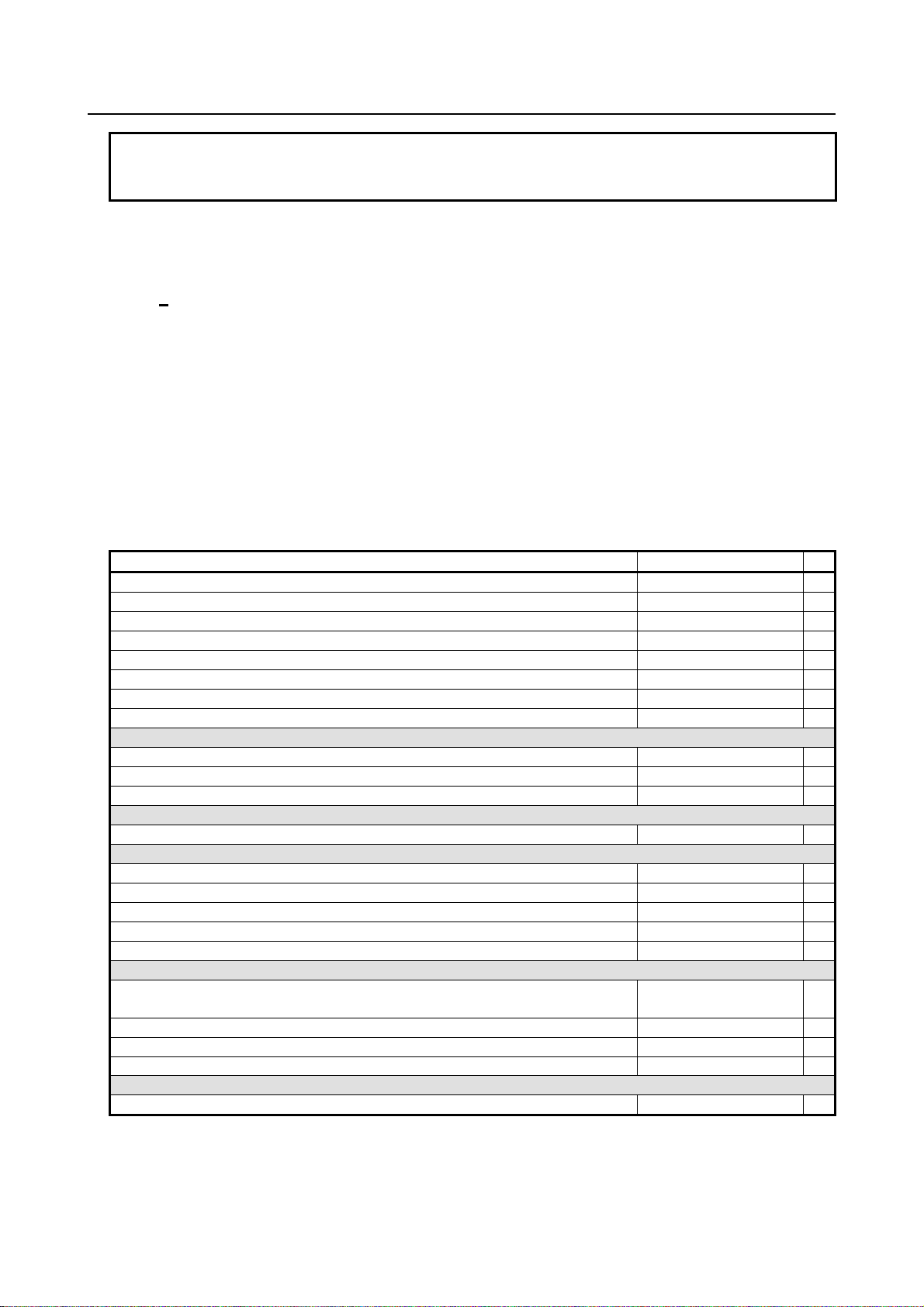
1.1 TOOL FIGURE AND TOOL MOTION BY PROGRAM
Explanation
- Machining using the end of cutter - Tool length compensation f unction
Usually, several tools are used for machining o ne workpiece. The tools have different tool length. It is
very troublesome to change the program in accordance with the tools.
Therefore, the length of each tool used should be measured in advance. By setting the differ ence between
the length of the standard tool and the length of each tool in the CNC (See Chapter, “Setting and
Displaying Data” in OPERATOR’S MANUAL (Common to Lathe System / Machining Center
System)(B-64694EN)), machining can be performed without altering the program even when the tool is
changed. This function is called tool length compensation (See Section, “Tool Length Compensation” in
OPERATOR’S MANUAL (Common to Lathe System / Machinin g Center System) (B-64694EN)).
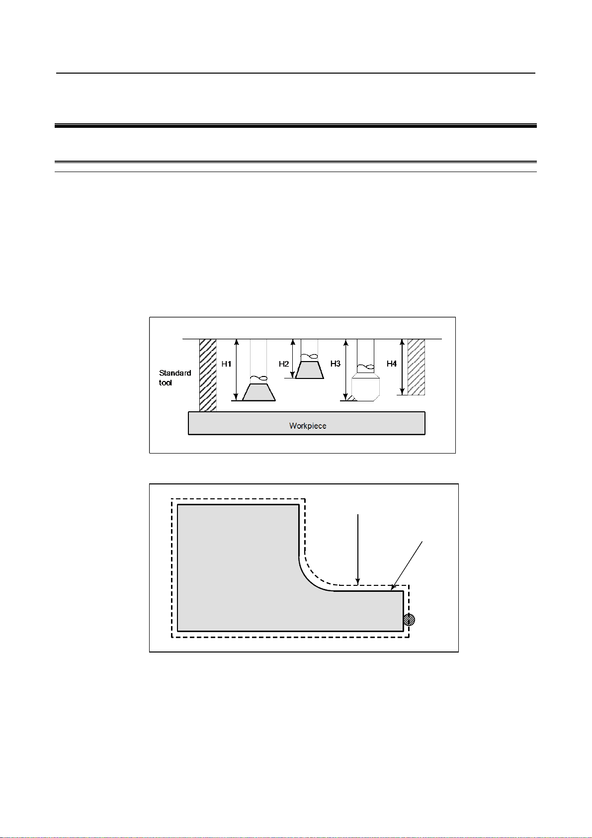
- Machining using the side of cutter - Cutter compensation function
Because a cutter has a radius, the center of the cutter path goes around the workpiece with the cutter
radius deviated.
If radius of cutters are stored in the CNC (See Chapter, “Setting and Displaying Data” in OPERATOR’S
MANUAL (Common to Lathe System / Machining Cent er Sy st em) (B-64694EN)), the tool can be moved
by cutter radius apart from the machining part figure. This function is called cutter compensation (See
Chapter, “Compensation Function”).
- 9 -
Page 26

2. PREPARATORY FUNCTION
(G FUNCTION)
PROGRAMMING B-64694EN-2/01
2 PREPARATORY FUNCTION
(G FUNCTION)
A number following address G determines the meaning of the command for the concerned block.
G codes are divided into the following two types.
Type Meaning
One-shot G code The G code is effective only in the block in which it is specified.
Modal G code The G code is effective until another G code of the same group is specified.
(Example)
G01 and G00 are modal G codes in group 01.
G01 X_ ;
Z_ ; G01 is effective in this range.
X_ ;
G00 Z_ ; G00 is effective in this range.
X_ ;
G01 X_ ;
:
Explanation
1. When the clear state (bit 6 (CLR) of parameter No. 3402) is set at power-up or reset, the modal G
codes are placed in the states described below.
(1) The modal G codes are placed in the states marked with
(2) G20 and G21 remain unchanged when the clear state is set at power-up or reset.
(3) Which status G22 or G23 at power on is set by bit 7 (G23) of parameter No. 3402. However,
G22 and G23 remain unchanged when the clear state is set at reset.
(4) The user can select G00 or G01 by setting bit 0 (G01) of parameter No. 3402.
(5) The user can select G90 or G91 by setting bit 3 (G91) of parameter No. 3402.
When G code system B or C is used in the lathe system, setting bit 3 (G91) of parameter No.
3402 determines which code, either G90 or G91, is effective.
(6) In the machining center system, the user can select G17, G18, or G19 by setting bits 1 (G18)
and 2 (G19) of parameter No. 3402.
2. G codes of group 00 other than G10 and G11 are one-shot G codes.
3. When a G code not listed in the G code list is specified, or a G code that has no corresponding
option is specified, alarm PS0010, “IMPROPER G-CODE” occurs.
4. Multiple G codes can be specified in the same block if each G code belongs to a different group. If
multiple G codes that belong to the same group are specified in the same block, only the last G code
specified is valid.
5. If a G code belonging to group 01 is specified in a canned cycle for drilling, the canned cycle for
drilling is cancelled. This means that the same state set by specifying G80 is set. Note that the G
codes in group 01 are not affected by a G code specifying a canned cycle for drilling.
6. G codes are indicated by group.
7. The group of G60 is switched according to the setting of the bit 0 (MDL) of parameter No. 5431.
(When the MDL bit is set to 0, the 00 group is selected. When the MDL bit is set to 1, the 01 group
is selected.)
as indicated in Table 2 .
- 10 -
Page 27

2. PREPARATORY FUNCTION
B-64694EN-2/01 PROGRAMMING
Table 2 G code list
G code Group Function
G00
G01 Linear interpolation (cutting feed)
G02 Circular interpolation CW or helical interpolation CW
G03 Circular interpolation CCW or helical interpolation CCW
G04
G04.1 G code preventing buffering
G05 AI contour control (high-precision contour control compatible command)
G05.1 AI contour control
G05.4 HRV3 on/off
G07.1
G08 AI contour control (advanced preview control compatible command)
G09 Exact stop
G10 Programmable data input
G10.6 Tool retract and recover
G11 Programmable data input mode cancel
G15
G16 Polar coordinates command
G17
G18 ZpXp plane selection
G19 YpZp plane selection
G20 (G70)
G21 (G71) Input in mm
G22
G23 Stored stroke check function off
G25
G26 Spindle speed fluctuation detection on
G27
G28 Automatic return to reference position
G28.2 In-position check disable reference position return
G29 Movement from reference position
G30 2nd, 3rd and 4th reference position return
G30.2 In-position check disable 2nd, 3rd, or 4th reference position return
G31 Skip function
G31.8 EGB-axis skip
G33 01 Threading
G37
G38 Tool radius/tool nose radius compensation : preserve vector
G39 Tool radius/tool nose radius compensation : corner circular interpolation
G40
G41 Tool radius/tool nose radius compensation : left
G42 Tool radius/tool nose radius compensation : right
G40.1
G41.1 Normal direction control on : left
G42.1 Normal direction control on : right
G43
G44 Tool length compensation G43.7 Tool offset
G45
G46 Tool offset : decrease
G47 Tool offset : double increase
G48 Tool offset : double decrease
G49 (G49.1) 08 Tool length compensation cancel
01
00
00
17
02
06
04
19
00
00
07
18
08
00
Positioning (rapid traverse)
Dwell
Cylindrical interpolation
Polar coordinates command cancel
XpYp plane selection Xp: X axis or its parallel axis
Input in inch
Stored stroke check function on
Spindle speed fluctuation detection off
Reference position return check
Automatic tool length measurement
Tool radius/tool nose radius compensation : cancel
Normal direction control cancel mode
Tool length compensation +
Tool offset : increase
(G FUNCTION)
Yp: Y axis or its parallel axis
Zp: Z axis or its parallel axis
- 11 -
Page 28

2. PREPARATORY FUNCTION
(G FUNCTION)
PROGRAMMING B-64694EN-2/01
Table 2 G code list
G code Group Function
G50
G51 Scaling
G50.1
G51.1 Programmable mirror image
G50.4
G50.5 Cancel composite control
G50.6 Cancel superimposed control
G51.4 Start synchronous control
G51.5 Start composite control
G51.6 Start superimposed control
G52
G53 Machine coordinate system setting
G53.1 Tool axis direction control
G53.2 Selecting a machine coordinate system with feedrate
G53.6 Tool center point retention type tool axis direction control
G54 (G54.1)
G55 Workpiece coordinate system 2 selection
G56 Workpiece coordinate system 3 selection
G57 Workpiece coordinate system 4 selection
G58 Workpiece coordinate system 5 selection
G59 Workpiece coordinate system 6 selection
G60 00 Single direction positioning
G61
G62 Automatic corner override
G63 Tapping mode
G64 Cutting mode
G65 00 Macro call
G66
G66.1 Macro modal call B
G67 Macro modal call A/B cancel
G68
G69 Coordinate system rotation cancel or 3-dimensional coordinate conversion mode off
G68.2 Tilted working plane indexing
G68.3 Tilted working plane indexing by tool axis direction
G68.4 Tilted working plane indexing (incremental multi-command)
G72.1
G72.2 Figure copying (linear copy)
G73
G74 Left-handed tapping cycle
G75 01 Plunge grinding cycle
G76 09 Fine boring cycle
G77
G78 Continuous-feed surface grinding cycle
G79 Intermittent-feed surface grinding cycle
G80 09
G80.4
G81.4 Electronic gear box: synchronization start
G80.5
G81.5 Electronic gear box 2 pair: synchronization start
G81 09
11
22
00
00
14
15
12
16
00
09
01
34
24
Scaling cancel
Programmable mirror image cancel
Cancel synchronous control
Local coordinate system setting
Workpiece coordinate system 1 selection
Exact stop mode
Macro modal call A
Coordinate system rotation start or 3-dimensional coordinate conversion mode on
Figure copying (rotary copy)
Peck drilling cycle
Plunge direct sizing/grinding cycle
Canned cycle cancel
Electronic gear box : synchronization cancellation
Electronic gear box: synchronization cancellation
Electronic gear box 2 pair: synchronization cancellation
Drilling cycle or spot boring cycle
Electronic gear box : synchronization start
- 12 -
Page 29

2. PREPARATORY FUNCTION
B-64694EN-2/01 PROGRAMMING
Table 2 G code list
G code Group Function
G81.1 00 High precision oscillation
G82
G83 Peck drilling cycle
G84 Tapping cycle
G84.2 Rigid tapping cycle (FS15 format)
G84.3 Left-handed rigid tapping cycle (FS15 format)
G85 Boring cycle
G86 Boring cycle
G87 Back boring cycle
G88 Boring cycle
G89 Boring cycle
G90
G91 Incremental programming
G91.1
G92 Setting for workpiece coordinate system or clamp at maximum spindle speed
G92.1 Workpiece coordinate system preset
G93
G94 Feed per minute
G95 Feed per revolution
G96
G97 Constant surface speed control cancel
G96.1
G96.2 Spindle indexing execution (not waiting for completion)
G96.3 Spindle indexing completion check
G96.4 SV speed control mode ON
G98
G99 Canned cycle : return to R point level
G107 00 Cylindrical interpolation
G160
G161 In-feed control
09
03
00
05
13
00
10
20
Drilling cycle or counter boring cycle
Absolute programming
Checking the maximum incremental amount specified
Inverse time feed
Constant surface speed control
Spindle indexing execution (waiting for completion)
Canned cycle : return to initial level
In-feed control cancel
(G FUNCTION)
- 13 -
Page 30
3. INTERPOLATION FUNCTION PROGRAMMING B-64694EN-2/01
G33IP_ F_ ;
F :Long axis direction lead
Z
X
Workpiece
Least command increment
Command value range of the lead
0.001 mm
F1 to F50000 (0.01 to 500.00mm)
0.0001 mm
F1 to F50000 (0.01 to 500.00mm)
0.0001 inch
F1 to F99999 (0.0001 to 9.9999inch)
0.00001 inch
F1 to F99999 (0.0001 to 9.9999inch)
3 INTERPOLATION FUNCTION
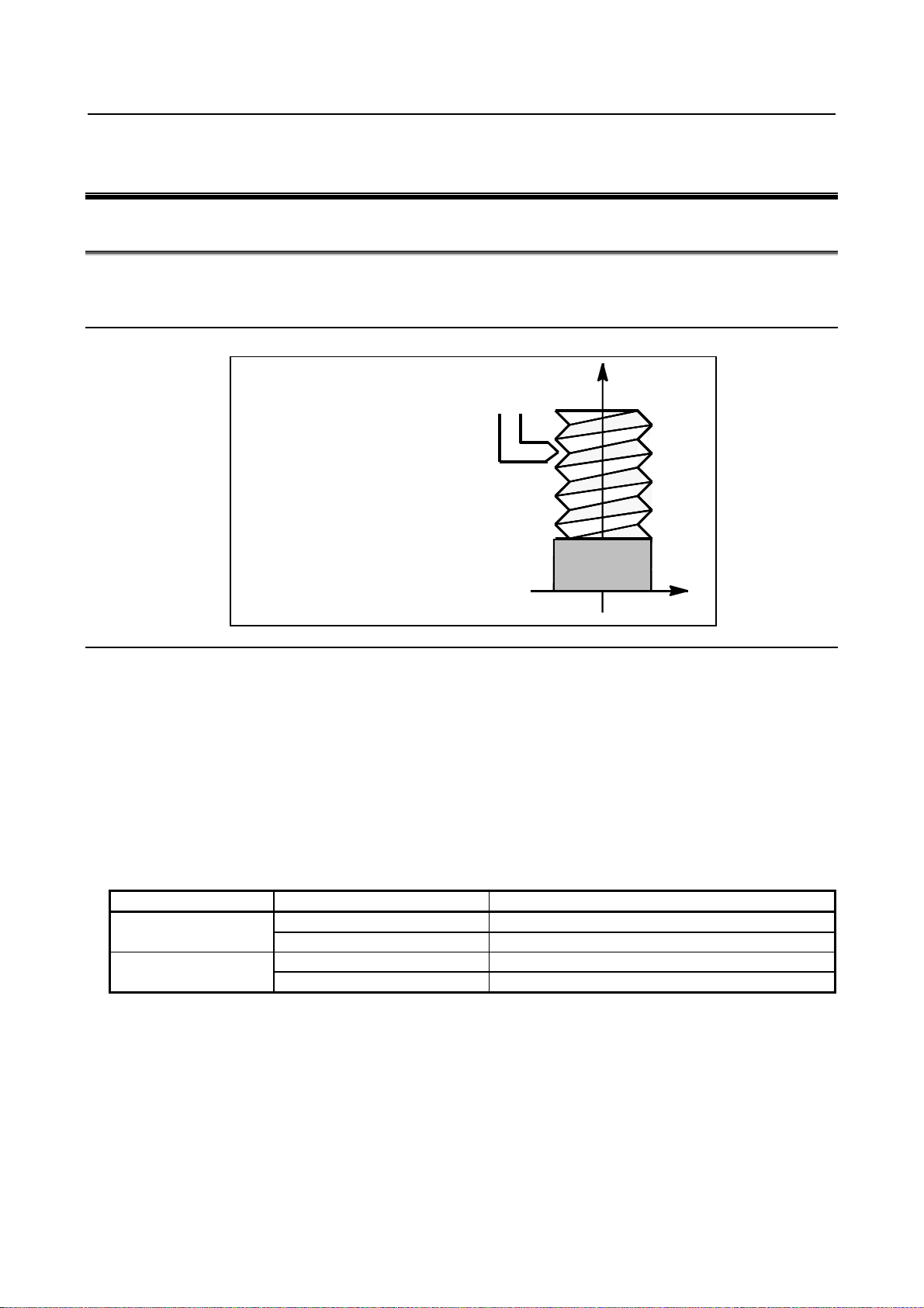
3.1 THREADING (G33)
Straight threads with a constant lead can be cut. The position coder mounted on the spindle reads the
spindle speed in real-time. The read spindle speed is converted to the feedr ate per minute to feed the tool.
Format
Explanation
In general, threading is repeated along the same tool path in rough cutting through finish cutting for a
screw. Since threading starts when the position coder mounted on the spindle outputs a 1-turn signal,
threading is started at a fixed point and the tool path on the workpiece is unchanged for repeated
threading. Note that the spindle speed must remain constant from rough cutting through finish cutting. If
not, incorrect thread lead will occur.
In general, the lag of the servo system, etc. will produce somewhat incorrect leads at the starting and
ending points of a thread cut. To compensate for this, a threading length somewhat longer than required
should be specified.
Table 3.1 (a) lists the ranges for specifyin g the thread lead.
Table 3.1 (a) Ranges of lead sizes th at can be specified
Metric input
Inch input
- 14 -
Page 31

B-64694EN-2/01 PROGRAMMING 3. INTERPOLATION FUNCTION
NOTE
1 The threading spindle speed which executes threading is limited as follows :
smaller
2 Cutting feedrate override is not applied to the converted feedrate in all machining
MANUAL (Common to Lathe System/Machining Center System) (B-64694EN).
Z
X
Workpiece
1.5mm
0 < spindle speed ≤ (Maximum cutting feedrate of threading axis(per rev.))
/ (Thread lead (length per rev.))
Spindle speed : min-1
Thread lead : mm or inch
Maximum cutting feedrate : mm/min or inch/min ; maximum command-specified
feedrate for feed-per-minute mode or maximum feedrate that is determined
based on mechanical restrictions including those related to motors, whichever is
process from rough cutting to finish cutting. The feedrate is fixed at 100%
3 The converted feedrate is limited by the upper feedrate specified.
4 Feed hold is disabled during threading. Pressing the feed hold key during
threading causes the machine to stop at the end point of the next block after
threading (that is, after the G33 mode is terminated)
5 The leads of a thread are generally incorrect, due to automatic acceleration and
deceleration. Thus distance allowances must be made to the extent in the
program. Refer “INCORRECT THREADED LENGTH” in the OPERATOR’S
Limitation
- Tool Retract and Recover
When the major axis for threading is specified as th e retraction axis, retraction is not performed. In this
case, after a block that does not specify threading is executed, an alarm PS0429, “ILLEGAL
COMMAND IN G10.6” is issued and the tool sto ps.
Example
Threading at a lead of 1.5mm
G33 Z10. F1.5;
- 15 -
Page 32

PROGRAMMING B-64694EN-2/01
4. COORDINATE VALUE AND
DIMENSION
Gxx Gyy G16; Starting the polar coordinate command
(polar coordinate mode)
G00 IP_ ;
:
Polar coordinate command
:
G15;
Canceling the polar coordinate command
(polar coordinate mode)
Second axis : angle of polar coordinate
Command position
Actual position
Angle
Radius
Command position
Actual position
Angle
Radius
When the angle is specified with an
absolute command
When the angle is speci
fied with an
incremental command
4 COORDINATE VALUE AND DIMENSION
4.1 POLAR COORDINATE COMMAND (G15, G16)
The end point coordinate value can be input in polar coordinates (radius and angle).
The plus direction of the angle is counterclockwise of the selected plane first axis + direction, and the
minus direction is clockwise.
Both radius and angle can be commanded in either absolute or incremental programming (G90, G91).
Format
G16 : Polar coordinate command
G15 : Polar coordinate command cancel
Gxx : Plane selection of the polar coordinate command (G17, G18 or G19)
Gyy : Center selection of the polar coordinate command (G90 or G91)
G90 specifies the origin of the program coordinate system as the origin of the
polar coordinate system, from which a radius is measured.
G91 specifies the current position as the origin of the polar coordinate
system, from which a radius is measured.
IP_ : Specifying the addresses of axes constituting the plane selected for the polar
coordinate system, and their values
First axis : radius of polar coordinate
- Setting the origin of the program coordinate system as the origi n of the polar
coordinate system
Specify the radius (the distance between the origin and the point) to be programmed with an absolute
programming. The origin of the program coordin ate system is set as the origin of the polar coordinate
system.
- 16 -
Page 33

B-64694EN-2/01 PROGRAMMING
4. COORDINATE VALUE AND
DIMENSION
When the angle is specified with an
incremental command
Command position
Actual position
Command position
Angle
Actual position
When the angle is specified with an
absolute command
Radius
Radius
Angle
PCC = 0
PCC = 1
When G16 has been commanded
[Example] G16 G91 G00 X20.0 Y30.0
commanded after reset (*1)
the selected plane 1st axis (radius)
the selected plane 1st axis (radius)
program coordinate system (*2)
command.
(angle)
coordinate command.
- Setting the current position as the origin of the polar coor di nate system
Specify the radius (the distance between the current position and the point) to be programmed with an
incremental programming. The current position is set as the origin of the polar coordinate system.
- Operation of which the address in the selected pl ane 1st axis (radius) or 2nd
axis (angle) is omitted
The behavior depends on bit 5 (PCC) of parameter No. 10351.
(PCC = 0 (FS0i specification), PCC = 1 (FS16i compatible specification))
The origin of the polar coordinate system
The origin of the polar coordinate system is decided according to Table 4.1 (a).
Table 4.1 (a) The origin of the polar coordinate system is decided
The origin of the program coordinate system
When Polar coordinate command has been
When the selected plane has been changed
(G17,G18,G19)
When the modal is G90 and there is the address of
When the modal is G91 and there is the address of
When there is not
the address of the
selected plane 1st
axis (radius) and
there is the
address of the
selected plane
2nd axis (angle)
When there is not the address of the selected plane
1st axis (radius) and the selected plane 2nd axis
When the origin of the polar
coordinate system before this
command is the origin of the
When the origin of the polar
coordinate system before this
command is the current position
(*3)
However, when the modal is G91 and there is the address
of the selected plane 1st axis (radius), the origin of the
polar coordinate system is the current position.
The origin of the program coordinate system
The current position
The origin of the program
coordinate system
The current position
In addition, the radius
becomes 0. Therefore, the
axis doesn't move by this
The origin of the polar coordinate system is not decided
because this command is not regarded as Polar
The origin of the program
coordinate system
*1 This means that Polar coordinate command is continued after reset in the polar coordinate command
mode.
This operation can use at reset state (bit 6 (CLR) of parameter No. 3402 is 0).
[Example]
G16 G90 G00 X100.0 Y45.0
:
RESET
G91 Y60.0 ......................... Polar coordinate command is continued after reset.
- 17 -
Page 34

PROGRAMMING B-64694EN-2/01
4. COORDINATE VALUE AND
DIMENSION
PCC = 0
PCC = 1
commanded
Therefore, the axes move to (X 35.355, Y 61.237).
*2 This means the following.
(1) G16 or the selected plane 1st axis (radius) in G90 is commanded.
(2) The origin of the program coordinate system is set to the origin of the polar coordinate.
(3) Thereafter, the selected plane 2nd axis (angle) is commanded without the address of the
selected plane 1st axis (radius).
[Example]
G16 .................................... The origin of the polar coordinate system is the origin of the
program coordinate system.
G91 Y60.0 ......................... There is not the ad dress of the selected plane 1st axis
(radius) and there is the address of the selected plane 2nd
axis (angle).
*3 This means the following.
(1) The selected plane 1st axis (radius) in G91 is commanded.
(2) The current position is set to the origin of the polar coordinate.
(3) Thereafter, the selected plane 2nd axis (angle) is commanded without the address of the
selected plane 1st axis (radius).
[Example]
G16
G91 X30.0 Y30.0 ............... The origin of the polar coordinate system is the current
position.
G90 Y40.0 ......................... There is no t the address of the selected plane 1st axis
(radius) and there is the address of the selected plane 2nd
axis (angle).
The radius and angle
The radius and the angle at following cases are set according to Table 4.1 (b).
- When G16 has been commanded.
- When Polar coordinate command has been commanded after reset.
- When the selected plane has been changed (G1 7, G18, G19).
Table 4.1 (b) The radius and the angle
When G16
has been
When Polar
coordinate
command
has been
commanded
after reset
The radius and the angle become 0.
When the radius or the angle is commanded at
the same time, the radius or the angle
becomes the value specified in the command.
[Example]
G90 G00 X50.0 Y50.0
G16 ............ The radius = 0, the angle = 0.
Y60.0 ......... The radius = 0, the angle = 60.0.
Therefore, the axes move to (X 0.0, Y 0.0).
- 18 -
The radius and the angle are calculated from the
current position.
When the radius or the angle is commanded at
the same time, the radius or the angle becomes
the value specified in the command.
[Example]
G90 G00 X50.0 Y50.0
G16 ........ The radius = 70.710,
the angle = 45.0.
(from the current position (X 50.0,
Y 50.0))
Y60.0 ..... The radius = 70.710,
the angle = 60.0.
Page 35

B-64694EN-2/01 PROGRAMMING
4. COORDINATE VALUE AND
DIMENSION
PCC = 0
PCC = 1
Therefore, the axes move to (Y 0.0, Z 0.0).
Therefore, the axes move to (Y 76.604, Z 64. 279 ).
- The origin of the program coordinate
system is set as the origin of the polar
coordinate system.
- The XY plane is selected.
Y
150°
30°
100mm
270°
X
When the
selected
plane has
been
changed
(G17,G18,
G19)
Example
Bolt hole circle
The radius and the angle become 0.
When the radius or the angle is commanded at
the same time, the radius or the angle
becomes the value specified in the command.
[Example]
G90 G16 G17
X100.0 Y30.0 ......... The radius = 100.0,
the angle = 30.0.
G19 Z40.0 ............The radius = 0,
the angle = 40.0.
The radius and the angle are succeeded.
When the radius or the angle is commanded at
the same time, the radius or the angle becomes
the value specified in the command.
[Example]
G90 G16 G17
X100.0 Y30.0 ......... The radius = 100.0,
the angle = 30.0.
G19 Z40.0 .... The radius = 100.0,
the angle = 40.0.
- Specifying angles and a radius with absolute programmings
N1 G17 G90 G16 ; Specifying the polar coordinate command and selecting the XY plane
Setting the origin of the program coordinate system as the origin of the polar
coordinate system
N2 G81 X100.0 Y30.0 Z-20.0 R-5.0 F200.0 ;
Specifying a distance of 100 mm and an angle of 30 deg
N3 Y150.0 ; Specifying a di st ance of 100 mm and an angle of 150 deg
N4 Y270.0 ; Specifying a di st ance of 100 mm and an angle of 270 deg
N5 G15 G80 ; Canceling the polar coordinate command
- Specifying angles with incremental programmings and a radi us with absolute
programmings
N1 G17 G90 G16; Specifying the polar coordinate command and selecting the XY plane
Setting the origin of the program coordinate system as the origin of the polar
coordinate system
N2 G81 X100.0 Y30.0 Z-20.0 R-5.0 F200.0 ;
Specifying a distance of 100 mm and an angle of 30 deg
N3 G91 Y120.0 ; Specifying a distance of 100 mm and an angle of +120 deg
N4 Y120.0 ; Specifying a distance of 100 mm and an angle of +120 deg
N5 G15 G80 ; Canceling the polar coordinate command
- 19 -
Page 36

PROGRAMMING B-64694EN-2/01
4. COORDINATE VALUE AND
DIMENSION
NOTE
adding new CNC function.
Limitation
- Specifying a radius in the polar coordinate m ode
In the polar coordinate mode, specify a radius for circular interpolation or helical interpolation (G02,
G03) with R.
- Axes that are not considered part of a polar coordinate command in the pol ar
coordinate mode
Axes specified for the following commands are not considered part of the polar coordinate command. The
command value is not converted by the polar coordinate command.
- Dwell (G04)
- Programmable data input (G10)
- Local coordinate system setting (G52)
- Workpiece coordinate system setting (G92)
- Machine coordinate system setting (G53)
- Stored stroke check (G22)
- Coordinate system rotation (G68)
- Scaling (G51)
- Tool retract and recover (G10.6)
- Workpiece coordinate system preset (G92.1)
- Figure copying (G72.1, G72.2)
- Cylindrical interpolation (G07.1, G107)
- Programmable mirror image (G51.1)
- Rotary axis
The polar coordinate command specify by the selected plane first axis and second axis. The polar
coordinate command cannot be specified with the axis that is set as a rotation axis.
- Function with limitation when using simultaneously
There is a limitation when the following functions are used together with the polar coordinate command.
For details of the limitations, refer to the explanation of each function.
- Retrace
- Inch/metric conversion
- Functions that cannot be used simultaneously
The following functions cannot be used together with the polar coordinate command.
- AI contour control
- Tilted working plane indexing
- Cs contour control
- Optional angle chamfering and corner rounding
“Axes that are not considered part of a polar coordinate command in the polar
coordinate mode”, “Function with limitation when using simultaneously” and
“Functions that cannot be used simultaneously” might be changed or added by
- 20 -
Page 37

B-64694EN-2/01 PROGRAMMING
5. FUNCTIONS TO SIMPLIFY
PROGRAMMING
Drilling
(-Z direction)
Operation at the
bottom of a hole
Retraction
(+Z direction)
G73
Intermittent feed
-
Rapid traverse
High-speed peck drilling cycle
G74
Feed
Dwell → Spindle CW
Feed
Left-hand tapping cycle
G76
Feed
Spindle orientation
Rapid traverse
Fine boring cycle
G80
- - -
Cancel
Drilling cycle, spot drilling
cycle
Drilling cycle, counter boring
cycle
G83
Intermittent feed
-
Rapid traverse
Peck drilling cycle
G84
Feed
Dwell → Spindle CCW
Feed
Tapping cycle
G85
Feed
-
Feed
Boring cycle
G86
Feed
Spindle stop
Rapid traverse
Boring cycle
G87
Feed
Spindle CW
Rapid traverse
Back boring cycle
G88
Feed
Dwell → Spindle stop
Manual
Boring cycle
G89
Feed
Dwell
Feed
Boring cycle
5 FUNCTIONS TO SIMPLIFY PROGRAMMING
5.1 CANNED CYCLE FOR DRILLING
Overview
Canned cycles for drilling make it easier for the programmer to create programs. With a canned cycle, a
frequently-used machining operation can be specified in a single block with a G function; without canned
cycles, normally more than one block is required. In addition, the use of canned cycles can shorten the
program to save memory.
Table 5.1 (a) lists canned cycles for drilling.
Table 5.1 (a) Canned cycles for drilling
G code
G81 Feed - Rapid traverse
G82 Feed Dwell Rapid traverse
Application
- 21 -
Page 38

PROGRAMMING B-64694EN-2/01
5. FUNCTIONS TO SIMPLIFY
PROGRAMMING
Operation 1
Feed
Initial level
Operation 2
Operation 6
Point R level
Operation 5
Operation 3
Rapid traverse
Operation 4
G code
Positioning plane
Drilling axis
G17
Xp-Yp plane
Zp
G18
Zp-Xp plane
Yp
G19
Yp-Zp plane
Xp
Explanation
A canned cycle for drilling consists of a sequence of six operations.
Operation 1 Positioning of axes X and Y (including also another axis)
Operation 2 Rapid traverse up to point R level
Operation 3 Hole machining
Operation 4 Operation at the bottom of a hole
Operation 5 Retraction to point R level
Operation 6 Rapid traverse up to the initial point
Fig. 5.1 (a) Operation sequence of canned cycle for drilling
- Positioning plane
The positioning plane is determined by plane selection code G17, G18, or G19.
The positioning axis is an axis other than the drilling axis.
- Drilling axis
Although canned cycles for drilling include tapping and boring cycles as well as drilling cycles, in this
chapter, only the term drilling will b e used to refer to operations implemented with canned cycles.
The drilling axis is a basic axis (X, Y, or Z) not used to define the positioning plane, or any axis parallel
to that basic axis.
The axis (basic axis or parallel axis) used as the drilling axis is determined according to the axis address
for the drilling axis specified in the same block as G codes G73 to G89.
If no axis address is specified for the drilling axis, the basic axis is assumed to be the drilling axis.
Table 5.1 (b) Positioning plane and drilling axis
Xp: X axis or an axis parallel to the X axis
Yp: Y axis or an axis parallel to the Y axis
Zp: Z axis o r an axis parallel to the Z axis
- 22 -
Page 39

B-64694EN-2/01 PROGRAMMING
5. FUNCTIONS TO SIMPLIFY
PROGRAMMING
CAUTION
Switch the drilling axis after canceling a canned cycle for drilling.
NOTE
drilling axis. When FXY=0, the Z axis is always the drilling axis.
G90 (Absolute programming)
G91 (Incremental programming)
Z = 0
R
Z
Point R
Point Z
R
Z
Point R
Point Z
Example
Assume that the U, V and W axes be parallel to the X, Y, and Z axes respectively. This condition is
specified by parameter No. 1022.
G17 G81 Z_ _ : The Z axis is used for drilling.
G17 G81 W_ _ : The W axis is used for drilling.
G18 G81 Y_ _ : The Y axis is used for drilling.
G18 G81 V_ _ : The V axis is used for drilling.
G19 G81 X_ _ : The X axis is used for drilling.
G19 G81 U_ _ : The U axis is used for drilling.
G17 to G19 may be specified in a block in which any of G73 to G89 is not specified.
A bit 0 (FXY) of parameter No. 5101 can be set to the Z axis always used as the
- Travel distance along the drilling axis G90/G91
The travel distance along the drilling axis varies for G90 and G91 as Fig. 5.1 (b):
Fig. 5.1 (b) Absolute programming and incremental programming
- Drilling mode
G73, G74, G76, and G81 to G89 are modal G codes an d remain in effect until canceled. When in effect,
the current state is the drilling mode.
Once drilling data is specified in the drilling mode, the data is retained until modified or canceled.
Specify all necessary drilling data at the beginning of canned cycles; when canned cycles are being
performed, specify data modifications only.
- 23 -
Page 40

PROGRAMMING B-64694EN-2/01
5. FUNCTIONS TO SIMPLIFY
PROGRAMMING
G98 (Return to initial level)
G99 (Return to point R level)
Initial level
Point R level
In the case of without ",D"
parameter to be used
G73
High-speed peck drilling cycle
No.5114
High-speed peck rigid tapping cycle,
Peck rigid tapping cycle
Peck drilling cycle
No.5115
Small-hole peck drilling cycle
No.5174
G84.2
Rigid tapping cycle (FS15 format)
No.5213
G84.3
Left-handed rigid tapping cycle (FS15 format)
No.5213
Number of repeats K The maximum command value = 9999
NOTE
For K, specify an integer of 0 or 1 to 9999.
- Return point level G98/G99
When the tool reaches the bottom of a hole, the tool may be returned to point R or to the initial level.
These operations are specified with G98 and G99. The operations performed when G98 and G99 are
specified are shown in Fig. 5.1 (c). Generally, G99 is used for the first drilling operation and G98 is used
for the last drilling operation.
The initial level does not change even when drilling is performed in the G99 mode.
Fig. 5.1 (c) Initial level and point R level
- Clearance
Clearance is commanded with an address D with a comma. If the cycle is commanded without ",D"
command, the clearance parameter will be valid. The cycles that can be commanded are as shown in
Table 5.1 (c).
If clearance is not programmed, use parameterized clearance. ",D" should be commanded in the block
where the drilling operation is performed. It is memorized as a modal command during canned cycle for
drilling. Decimal point input is possible for the ",D" command.
Table 5.1 (c) List of canned cycle for drilling which clearance can be commanded
G code Function
G74, G84
G83
command, the clearance
No.5213
- Repeat
To repeat drilling for equally-spaced holes, specify the number of repeats in K_.
K is effective only within the block where it is specified.
Specify the first hole position in incremental programming (G91).
If it is specified in absolute programming (G90), drilling is repeated at the same position.
If K0 is specified, drilling data is stored, but drilling is not performed.
- 24 -
Page 41

B-64694EN-2/01 PROGRAMMING
5. FUNCTIONS TO SIMPLIFY
PROGRAMMING
Positioning (rapid traverse G00)
Cutting feed (linear interpolation G01)
Manual feed
OSS
Oriented spindle stop (The spindle stops at a fi xed rotation position)
P
Dwell
- Single block
If a drilling cycle is performed in a single block, the control unit stops at each of the end points of
operations 1, 2, and 6 in Fig. 5.1 (a). This means that three starts are made to make a single hole. At th e
end points of operations 1 and 2, the feed hold lamp turns on and the control unit stops. If the repetitive
count is not exhausted at the end point of operation 6, the control unit stops in the feed hold mode, and
otherwise, stops in the single block stop mode. Note that G87 does not cause a stop at point R in G87.
G88 causes a stop at point Z after a dwell.
- Cancel
To cancel a canned cycle, use G80 or a gro up 01 G code.
Group 01 G codes
G00 : Positioning (rapid traverse)
G01 : Linear interpolation
G02 : Circular interpolation or helical interpolation (CW)
G03 : Circular interpolation or helical interpolation (CCW)
- Symbols in figures
Subsequent sections explain the individual canned cycles. Figures in these Explanation use the following
symbols:
Shift (rapid traverse G00)
- 25 -
Page 42

PROGRAMMING B-64694EN-2/01
5. FUNCTIONS TO SIMPLIFY
PROGRAMMING
G73 X_ Y_ Z_ R_ Q_ ,D_ F_ K_ ;
K_ : Number of repeats (if required)
G73 (G98)
G73 (G99)
Point R
q
qqd
d
Point Z
Initial level
Point R level
Point R
q
qqd
d
Point Z
5.1.1 High-Speed Peck Drilling Cycle (G73)
This cycle performs high-speed peck drilling. It performs intermittent cutting feed to the bottom of a hole
while removing chips from the hole.
Format
X_ Y_ : Hole position data
Z_ : The distance from point R to the bottom of the hole
R_ : The distance from the initial level to point R level
Q_ : Depth of cut for each cutting feed
,D_ : Clearance
F_ : Cutting feedrate
Explanation
- Operations
The high-speed peck drilling cycle performs intermittent feeding along the Z-axis. When this cycle is
used, chips can be removed from the hole easily, and a smaller val ue can b e set for retractio n. This allows,
drilling to be performed efficiently. Set the clearance, d, in ",D" command or parameter No. 5114.
The tool is retracted in rapid traverse.
- Spindle rotation
Before specifying G73, rotate the spindle using an auxiliary function (M code).
- Auxiliary function
When the G73 code and an M code are specified in the same block, the M code is executed at the time of
the first positioning operation. When K is used to specify the number of repeats, the M code is executed
for the first hole only; for the second and subsequent holes, the M code is not executed.
- Tool length compensation
When a tool length compensation (G43, G44, or G49) is specified in the canned cycle for drilling, the
offset is applied after the time of positioning to point R.
- 26 -
Page 43

B-64694EN-2/01 PROGRAMMING
5. FUNCTIONS TO SIMPLIFY
PROGRAMMING
Limitation
- Axis switching
Before the drilling axis can be changed, the canned cycle for drilling must be canceled.
- Drilling
In a block that does not contain X, Y, Z, R, or any other axes, drilling is not performed.
- Q
Specify Q in blocks that perform drilling. If they are specified in a block that does not perform drilling,
they cannot be stored as modal data.
- Cancel
Do not specify a G code of the 01 group (G00 to G03) and G73 in a single block. Otherwise, G73 will be
canceled.
- Tool offset
In the canned cycle mode for drilling, tool offsets are i gnored.
Example
M3 S2000 ; Cause the spindle to start rotating.
G90 G99 G73 X300.0 Y-250.0 Z-150.0 R-100.0 Q15.0 F120 ;
Position, drill hole 1, then return to point R.
Y-550.0 ; Position, drill hole 2, then return to point R.
Y-750.0 ; Position, drill hole 3, then return to point R.
X1000.0 ; Position, drill hole 4, then return to point R.
Y-550.0 ; Position, drill hole 5, then return to point R.
G98 Y-750.0 ; Position, drill hole 6, then return to the initial level.
G80 G28 G91 X0 Y0 Z0 ; Return to the reference position
M5 ; Cause the spindle to stop rotating.
- 27 -
Page 44
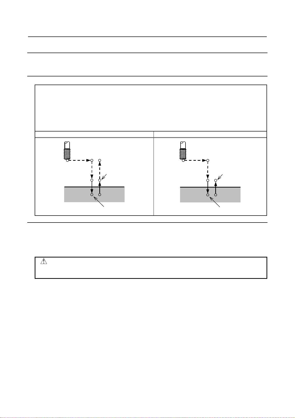
PROGRAMMING B-64694EN-2/01
5. FUNCTIONS TO SIMPLIFY
PROGRAMMING
G74 X_ Y_ Z_ R_P_ F_ K_ ;
K_ : Number of repeats (if required)
G74 (G98)
G74 (G99)
Point R
Point Z
P
P
Spindle CW
Spindle
CCW
Initial level
Point R
Point Z
P
P
Spindle CW
Spindle
CCW
Point R level
CAUTION
stop the machine until the return operation is completed.
5.1.2 Left-Handed Tapping Cycle (G74)
This cycle performs left-handed tapping. In the left-handed tapping cycle, when the bottom of the hole
has been reached, the spindle rotates clockwise.
Format
X_ Y_ : Hole position data
Z_ : The distance from point R to the bottom of the hole
R_ : The distance from the initial level to point R level
P_ : Dwell time
F_ : Cutting feedrate
Explanation
- Operations
Tapping is performed by turning the spindle counterclockwise. When the bottom of the hole has been
reached, the spindle is rotated clockwise fo r retraction. This creates a reverse thread.
Feedrate overrides are ignored during left-handed tapping. A feed hold does not
- Spindle rotation
Before specifying G74, use an auxiliary function (M code) to rotate the spindle counterclockwise.
If drilling is continuously performed with a small value specified for the distance between the hole
position and point R level or between the initial level and point R level, the normal spindle speed may not
be reached at the start of hole cutting op eration. In this case, insert a d well before each drilling operation
with G04 to delay the operation, without specifying the number of repeats for K. For some machines, the
above note may not be considered. Refer to the manual provided by the machine tool builder.
- Auxiliary function
When the G74 command and an M code are specified in the same block, the M code is ex ecuted at the
time of the first positioning operation. When K is used to specify the n umber of repeats, the M code is
executed for the first hole only; for the second and subsequent holes, the M code is not executed.
- Tool length compensation
When a tool length compensation (G43, G44, or G49) is specified in the canned cycle for drilling, the
offset is applied after the time of positioning to point R.
- 28 -
Page 45

B-64694EN-2/01 PROGRAMMING
5. FUNCTIONS TO SIMPLIFY
PROGRAMMING
Limitation
- Axis switching
Before the drilling axis can be changed, the canned cycle for drilling must be canceled.
- Drilling
In a block that does not contain X, Y, Z, R, or any other axes, drilling is not performed.
- P
Specify P in blocks that perform drilling. If it is specified in a block that does not perform drilling, it
cannot be stored as modal data.
- Cancel
Do not specify a G code of the 01 group (G00 to G03) and G74 in a single block. Otherwise, G74 will be
canceled.
- Tool offset
In the canned cycle mode for drilling, tool offsets are ignored.
Example
M4 S100 ; Cause the spindle to start rotating.
G90 G99 G74 X300.0 Y-250.0 Z-150.0 R-120.0 F120 ; Position, tapping hole 1, then return to point R.
Y-550.0 ; Position, tapping hole 2, then return to point R.
Y-750.0 ; Position, tapping hole 3, then return to point R.
X1000.0 ; Position, tapping hole 4, then return to point R.
Y-550.0 ; Position, tapping hole 5, then return to point R.
G98 Y-750.0 ; Position, tapping hole 6, then return to the initial
level.
G80 G28 G91 X0 Y0 Z0 ; Return to the ref erence position
M5 ; Cause the spindle to stop rotating.
- 29 -
Page 46

PROGRAMMING B-64694EN-2/01
5. FUNCTIONS TO SIMPLIFY
PROGRAMMING
G76 X_ Y_ Z_ R_ Q_ P_ F_ K_ ;
K_ : Number of repeats (if required)
Spindle CW
Initial level
Point R
Point Z
q
P
OSS
Spindle CW
Point R level
Point R
Point Z
q
P
OSS
Shift amount q
Spindle orientation
Tool
5.1.3 Fine Boring Cycle (G76)
The fine boring cycle bores a hole precisely. When the bottom of the hole has been reached, the spindle
stops, and the tool is moved away from the machined surface of the workpiece and retracted.
Format
X_ Y_ : Hole position data
Z_ : The distance from point R to the bottom of the hole
R_ : The distance from the initial level to point R level
Q_ : Shift amount at the bottom of a hole
P_ : Dwell time at the bottom of a hole
F_ : Cutting feedrate
G76(G98) G76(G99)
Explanation
- Operations
When the bottom of the hole has been reached, the spindle is stopped at the fixed rotation position, and
the tool is moved in the direction opposite to the tool nose and retracted. This ensures that the machined
surface is not damaged and enables precise and efficient boring to be performed.
- Spindle rotation
Before specifying G76, use a Auxiliary function (M code) to rotate the spindle.
- Auxiliary function
When the G76 command and an M code are specified in the same block, the M code is ex ecuted at the
time of the first positioning operation. When K is used to specify the n umber of repeats, the M code is
executed for the first hole only; for the second and subsequent holes, the M code is not executed.
- Tool length compensation
When a tool length compensation (G43, G44, or G49) is specified in the canned cycle for drilling, the
offset is applied after the time of positioning to point R.
- 30 -
Page 47

B-64694EN-2/01 PROGRAMMING
5. FUNCTIONS TO SIMPLIFY
PROGRAMMING
CAUTION
cut for G73 and G83.
Limitation
- Axis switching
Before the drilling axis can be changed, the canned cycle for drilling must be canceled.
- Drilling
In a block that does not contain X, Y, Z, R, or any additional axes, drilling is not performed.
- P, Q
Be sure to specify a positive value in Q. If Q is specified with a n egative value, the sign is ignored. Set
the direction of shift in the parameter No.5148.
Specify P and Q in a block that performs drilling. If they are specified in a block that does not perform
drilling, they are not stored as modal data.
Q (shift at the bottom of a hole) is a modal value retained within canned cycles
for drilling. It must be specified carefully because it is also used as the depth of
- Cancel
Do not specify a G code of the 01 group (G00 to G03) and G76 in a single block. Otherwise, G76 will be
canceled.
- Tool offset
In the canned cycle mode for drilling, tool offsets are igno red.
Example
M3 S500 ; Cause the spindle to start rotating.
G90 G99 G76 X300.0 Y-250.0 Position, bore hole 1, then return to point R.
Z-150.0 R-120.0 Q5.0 Orient at the bottom of the hole, then shift by 5 mm.
P1000 F120 ; Stop at the bottom of the hole for 1 sec.
Y-550.0 ; Position, drill hole 2, then return to point R.
Y-750.0 ; Position, drill hole 3, then return to point R.
X1000.0 ; Position, drill hole 4, then return to point R.
Y-550.0 ; Position, drill hole 5, then return to point R.
G98 Y-750.0 ; Position, drill hole 6, then return to the initial level.
G80 G28 G91 X0 Y0 Z0 ; Return to the reference position
M5 ; Cause the spindle to stop rotating.
- 31 -
Page 48

PROGRAMMING B-64694EN-2/01
5. FUNCTIONS TO SIMPLIFY
PROGRAMMING
G81 X_ Y_ Z_ R_ F_ K_ ;
K_ : Number of repeats (if required)
G81 (G98)
G81 (G99)
Initial level
Point R
Point Z
Point R level
Point R
Point Z
5.1.4 Drilling Cycle, Spot Drilling (G81)
This cycle is used for normal drilling. Cutting feed is performed to the bottom of the hole. The tool is then
retracted from the bottom of the hole in rapid traverse.
Format
X_ Y_ : Hole position data
Z_ : The distance from point R to the bottom of the hole
R_ : The distance from the initial level to point R level
F_ : Cutting feedrate
Explanation
- Operations
After positioning along the X- and Y-axes, rapid traverse is performed to point R.
Drilling is performed from point R to point Z.
The tool is then retracted in rapid traver se.
- Spindle rotation
Before specifying G81, use an auxiliary function (M code) to rotate the spindle.
- Auxiliary function
When the G81 command and an M code are specified in the same block, the M code is ex ecuted at the
time of the first positioning operation. When K is used to specify the n umber of repeats, the M code is
performed for the first hole only; for the second and subsequent holes, the M code is not executed.
- Tool length compensation
When a tool length compensation (G43, G44, or G49) is specified in the canned cycle for drilling, the
offset is applied after the time of positioning to point R.
Limitation
- Axis switching
Before the drilling axis can be changed, the canned cycle for drilling must be canceled.
- Drilling
In a block that does not contain X, Y, Z, R, or any other axes, drilling is not performed.
- 32 -
Page 49

B-64694EN-2/01 PROGRAMMING
5. FUNCTIONS TO SIMPLIFY
PROGRAMMING
G82 X_ Y_ Z_ R_ P_ F_ K_ ;
K_ : Number of repeats (if required)
G82 (G98)
G82 (G99)
Initial level
Point R
Point Z
P
Point R level
Point R
Point Z
P
- Cancel
Do not specify a G code of the 01 group (G00 to G03) and G81 in a single block. Otherwise, G81 will be
canceled.
- Tool offset
In the canned cycle mode for drilling, tool offsets are ignored.
Example
M3 S2000 ; Cause the spindle to start rotating.
G90 G99 G81 X300.0 Y-250.0 Z-150.0 R-100.0 F120 ; Position, drill hole 1, then return to point R.
Y-550.0 ; Position, drill hole 2, then return to point R.
Y-750.0 ; Position, drill hole 3, then return to point R.
X1000.0 ; Position, drill hole 4, then return to point R.
Y-550.0 ; Position, drill hole 5, then return to point R.
G98 Y-750.0 ; Position, drill ho le 6, then return to the initial
level.
G80 G28 G91 X0 Y0 Z0 ; Return to the reference position
M5 ; Cause the spindle to stop rotating.
5.1.5 Drilling Cycle Counter Boring Cycle (G82)
This cycle is used for normal drilling.
Cutting feed is performed to the bottom of the hole. At the bottom, a dwell is performed, then the tool is
retracted in rapid traverse.
This cycle is used to drill holes more accurately with respect to depth.
Format
X_ Y_ : Hole position data
Z_ : The distance from point R to the bottom of the hole
R_ : The distance from the initial level to point R level
P_ : Dwell time at the bottom of a hole
F_ : Cutting feed rate
- 33 -
Page 50

PROGRAMMING B-64694EN-2/01
5. FUNCTIONS TO SIMPLIFY
PROGRAMMING
Explanation
- Operations
After positioning along the X- and Y-axes, rapid traverse is performed to point R.
Drilling is then performed from point R to point Z.
When the bottom of the hole has been reached, a dwell is performed. The tool is then retracted in rapid
traverse.
- Spindle rotation
Before specifying G82, use an auxiliary function (M code) to rotate the spindle.
- Auxiliary function
When the G82 command and an M code are specified in the same block, the M code is ex ecuted at the
time of the first positioning operation. When K is used to specify the n umber of repeats, the M code is
executed for the first hole only; for the second and subsequent holes, the M code is not executed.
- Tool length compensation
When a tool length compensation (G43, G44, or G49) is specified in the canned cycle for drilling, the
offset is applied after the time of positioning to point R.
Limitation
- Axis switching
Before the drilling axis can be changed, the canned cycle for drilling must be canceled.
- Drilling
In a block that does not contain X, Y, Z, R, or any other axes, drilling is not performed.
- P
Specify P in blocks that perform drilling. If it is specified in a block that does not perform drilling, it
cannot be stored as modal data.
- Cancel
Do not specify a G code of the 01 group (G00 to G03) and G82 in a single block. Otherwise, G82 will be
canceled.
- Tool offset
In the canned cycle mode for drilling, tool offsets are ignored.
Example
M3 S2000 ; Cause the spindle to start rotating.
G90 G99 G82 X300.0 Y-250.0 Z-150.0 R-100.0 P1000 F120 ;
Position, drill hole 1, and dwell for 1 sec at the bottom of the hole, then
return to point R.
Y-550.0 ; Position, drill hole 2, then return to point R.
Y-750.0 ; Position, drill hole 3, then return to point R.
X1000.0 ; Position, drill hole 4, then return to point R.
Y-550.0 ; Position, drill hole 5, then return to point R.
G98 Y-750.0 ; Position, drill hole 6, then return to the initial level.
G80 G28 G91 X0 Y0 Z0 ; Return to the reference position
M5 ; Cause the spindle to stop rotating.
- 34 -
Page 51

B-64694EN-2/01 PROGRAMMING
5. FUNCTIONS TO SIMPLIFY
PROGRAMMING
G83 X_ Y_ Z_ R_ Q_ ,D_ F_ K_ ;
K_ : Number of repeats (if required)
G83 (G98)
G83 (G99)
q
q
q d
d
Point R
Point Z
Initial level
q
q
q
d
d
Point R
Point Z
Point R level
5.1.6 Peck Drilling Cycle (G83)
This cycle performs peck drilling.
It performs intermittent cutting feed to the bottom of a hole while removing shavings from the hole.
Format
X_ Y_ : Hole position data
Z_ : The distance from point R to the bottom of the hole
R_ : The distance from the initial level to point R level
Q_ : Depth of cut for each cutting feed
,D_ : Clearance
F_ : Cutting feedrate
Explanation
- Operations
Q represents the depth of cut for each cutting feed. It must always be specified as an incremental valu e.
In the second and subsequent cutting feeds, rapid traverse is performed up to a point that lies at a distance
of d just before where the last drilling has ended. Th en, the cutting feed is performed from the point again.
d is set in ",D" command or parameter No.5115.
Be sure to specify a positive value in Q. Negative values are ignored.
- Spindle rotation
Before specifying G83, use an auxiliary function (M code) to rotate the spindle.
- Auxiliary function
When the G83 command and an M code are specified in the same block, the M code is ex ecuted at the
time of the first positioning operation. When K is used to specify the number of repeats, the M code is
executed for the first hole only; for the second and subsequent holes, the M code is not executed.
- Tool length compensation
When a tool length compensation (G43, G44, or G49) is specified in the canned cycle for drilling, the
offset is applied after the time of positioning to point R.
- 35 -
Page 52

PROGRAMMING B-64694EN-2/01
5. FUNCTIONS TO SIMPLIFY
PROGRAMMING
Limitation
- Axis switching
Before the drilling axis can be changed, the canned cycle for drilling must be canceled.
- Drilling
In a block that does not contain X, Y, Z, R, or any other axes, drilling is not performed.
- Q
Specify Q in blocks that perform drilling. If they are specified in a block that does not perform drilling,
they cannot be stored as modal data.
- Cancel
Do not specify a G code of the 01 group (G00 to G03) and G83 in a single block. Otherwise, G83 will be
canceled.
- Tool offset
In the canned cycle mode for drilling, tool offsets are ignored.
Example
M3 S2000 ; Cause the spindle to start rotating.
G90 G99 G83 X300.0 Y-250.0 Z-150.0 R-100.0 Q15.0 F120.0 ;
Position, drill h ole 1, then return to point R.
Y-550.0 ; Position, drill hole 2, then return to point R.
Y-750.0 ; Position, drill hole 3, then return to point R.
X1000.0 ; Position, drill hole 4, then return to point R.
Y-550.0 ; Position, drill hole 5, then return to point R.
G98 Y-750.0 ; Position, drill hole 6, then return to the initial level.
G80 G28 G91 X0 Y0 Z0 ; Return to the reference position
M5 ; Cause the spindle to stop rotating.
- 36 -
Page 53

B-64694EN-2/01 PROGRAMMING
5. FUNCTIONS TO SIMPLIFY
PROGRAMMING
G83 X_ Y_ Z_ R_ Q_ ,D_ F_ I_ K_ P_ ;
(If this is omitted, P0 is assumed as the default.)
G83 (G98)
G83 (G99)
∆
∆
Point R
Point Z
q
Initial level
Dwell
Overload torque
∆
Point R
Point Z
q
Dwell
Overload torque
Point R level
∆
()
5.1.7 Small-Hole Peck Drilling Cycle (G83)
An arbor with the overload torque detection function is used to retract the tool when the overload torque
detection signal (skip signal) is detected during drilling. Drilling is resumed after the spindle speed and
cutting feedrate are changed. These steps are repeated in this peck drilling cycle.
The mode for the small–hole peck drilling cycle is selected when the M cod e in parameter No. 5163 is
specified. The cycle can be started by specifying G83 in this mode. This mode is canceled when G80 is
specified or when a reset occurs.
Format
X_ Y_ : Hole position data
Z_ : Distance from point R to the bottom of the hole
R_ : Distance from the initial level to point R
Q_ : Depth of each cut
,D_ : Clearance
F_ : Cutting feedrate
I_ : Forward or backward traveling speed (same format as F above)
(If this is omitted, the values in parameters Nos. 5172 and 5173 are
assumed as defaults.)
K_ : Number of times the operation is repeated (if required)
P_ : Dwell time at the bottom of the hole
∆: Initial clearance when the tool is retracted to point R and the clearance from the bottom of the hole in the
second or subsequent drilling (",D" command or parameter No. 5174)
q: Depth of each cut
Path along which the tool travels at the rapid traverse rate
Path along which the tool travels at the programmed cutting feedrate
Path along which the tool travels at the forward or backward rate specified with parameters during the cycle
- 37 -
Page 54

PROGRAMMING B-64694EN-2/01
5. FUNCTIONS TO SIMPLIFY
PROGRAMMING
NOTE
target point as previous advancing.
Explanations
- Component operations of the cycle
* X- and Y-axis positioning
* Positioning at point R along the Z-axis
* Cutting along the Z-axis (first time, depth of cut Q, incremental)
Retracting (bottom of hole → minimum clearance ∆, incremental)
Retracting (bottom of hole + clearance ∆ → point R, absolute)
Forwarding (point R → bottom of hole + clearance ∆, absolute)
Cutting (second and subsequent times, cut of depth Q + ∆, incremental)
* Dwell
* Return to point R along the Z-axis (or initial point) = end of cycle
Acceleration/deceleration during advancing and retraction is controlled according to the cutting feed
acceleration/deceleration time constant.
When retraction is performed, the position is checked at point R.
- Specifying an M code
When the M code in parameter No. 51 63 is specified , the system enters th e mode for the small–hole peck
drilling cycle.
This M code does not wait for F IN. Care must be taken when this M code is specified with another M
code in the same block.
(Example) M03 M□□ ; → Waits for FIN.
M□□ M03 ; → Does not wait for FIN.
- Specifying a G code
When G83 is specified in the mode for the small-hole peck drilling cycle, the cycle is started.
This continuous–state G code remains unchanged until another canned cycle is specified or until the G
code for canceling the canned cycle is specified. This eliminates the need for specifying drilling data in
each block when identical drilling is repeated.
- Signal indicating that the cycle is in progress
In this cycle mode, the small-hole peck drilling cycle in progress signal is set to "1" at the start of point R
positioning on the axis in the drilling direction after G83 is specified and positioning is performed to the
specified hold position. This signal is set to "0" if another canned cycle is specified or if this mode is
canceled with G80, a reset, or an emergency stop. For details, refer to the manual of the machine tool
builder.
- Overload torque detection signal
A skip signal is used as the overload torq ue detection signal. The skip signal is effective while the tool i s
advancing or drilling and the tool tip is between points R and Z. (The signal causes a retraction). For
details, refer to the manual of the machine tool builder.
When receiving overload torque detect signal while the tool is advancing, the tool
will be retracted (clearance ∆ and to the point R), then advanced to the same
- 38 -
Page 55

B-64694EN-2/01 PROGRAMMING
5. FUNCTIONS TO SIMPLIFY
PROGRAMMING
Cutting feedrate = F × α
Spindle speed = S × γ
- Changing the drilling conditions
In a single G83 cycle, drilling conditions are changed for each drilling operation (advance → drilling →
retraction). Bits 1 and 2 of parameter OLS, NOL No. 5160 can be specified to supp ress the change in
drilling conditions.
1 Changing the cutting feedrate
The cutting feedrate programmed with the F code is changed for each of the second and subsequent
drilling operations. In parameters Nos.5166 and 5167, specify the respective rates of change applied
when the skip signal is detected and when it is not detected in the previous drilling operation.
<First drilling> α=1.0
<Second or subsequent drilling>
α=α×β÷100, where β is the rate of change for each drilling operation
When the skip signal is detected during the previous drilling operation: β=b1% (parameter No.5166)
When the skip signal is not detected during the previous drilling operation: β=b2% (parameter
No.5167)
If the rate of change in cutting feedrate becomes smaller than the rate specified in parameter No.
5168, the cutting feedrate is not changed.
The cutting feedrate can be increased up to the maximum cutting feedrate.
2 Changing the spindle speed
The spindle speed programmed with the S code is changed for each of the second and subsequent
advances. In parameters Nos. 5164 and 5165, specify the rates of change applied when the skip
signal is detected and when it is not detected in the previous drilling operation.
<First drilling> γ=1.0
<Second or subsequent drilling>
γ=γ×δ÷100, where δ is the rate of change for each drilling operation
When the skip signal is detected during the previous drilling operation: δ=d1% (parameter No.5164)
When the skip signal is not detected during the previous drilling operation: δ=d2% (parameter
No.5165)
When the cutting feedrate reaches the minimum rate, the spindl e speed is not changed. The spindle
speed can be increased up to a value corresponding to the maximum value of S analog data.
- Advance and retraction
Advancing and retraction of the tool are not executed in the same manner as rapid -traverse positioning.
Like cutting feed, the two operations are carried out as interpolated operations. Note that the tool life
management function excludes advancing and retraction from the calculation of the tool life.
- Specifying address I
The forward or backward traveling speed can be specified wit h address I in the same format as address F,
as shown below:
G83 I1000 ; (without decimal point)
G83 I1000. ; (with decimal point)
Both commands indicate a speed of 1000 mm/min.
Address I specified with G83 in the continuous-state mode continues to be valid until G80 is specified or
until a reset occurs.
- 39 -
Page 56

PROGRAMMING B-64694EN-2/01
5. FUNCTIONS TO SIMPLIFY
PROGRAMMING
NOTE
cutting feedrate specified by F.
NOTE
small-hole peck drilling cycle mode.
If address I is not specified and parameter No.5172 (for backward) or No.5173
(for forward) is set to 0, the forward or backward travel speed is same as the
- Functions that can be specified
In this canned cycle mode, the following functions can be specified:
- Hole position on the X-axis, Y-axis, and additional axis
- Operation and branch by custom macro
- Subprogram (hole position group, etc.) calling
- Switching between absolute and incremental modes
- Coordinate system rotation
- Scaling (This command will not affect depth of cut Q or small clearance ∆.)
- Dry run
- Feed hold
- Single block
When single-block operation is enabled, drilling is stopped after each retraction. Also, a single block stop
is performed by setting bit 0 (SBC) of parameter No. 5105.
- Feedrate override
The feedrate override function works during cutting, retraction, and advancing in the cycle.
- Custom macro interface
The number of retractions made during cutting and the number of retractions made in response to the
overload signal received during cutting can be output to custom macro common variables (#100 to #149)
specified in parameters Nos.5170 and 5171. Parameters Nos.5170 and 5171 can specify variable numbers
within the range of #100 to #149.
Parameter No.5170: Specifies the number of the common variable to which the number of retractions
made during cutting is output.
Parameter No.5171: Specifies the number of the common variable to which the number of retractions
made in response to the overload signal received during cutting is output.
The numbers of retraction output to common variables are cleared by G83 while
- Positioning to hole position
When positioning the axes to hole position (axes X and Y when XY plane is used) in Small-hole peck
drilling cycle, the machining time can be shortened by the spindle is not stopped.
This function is enabled by the parameter SPH(No.5108#6).
Limitation
- Subprogram call
In the canned cycle mode, specify the subprogram call command M98P_ in an independent block.
- 40 -
Page 57

B-64694EN-2/01 PROGRAMMING
5. FUNCTIONS TO SIMPLIFY
PROGRAMMING
G84 X_ Y_ Z_ R_ P_ F_ K_ ;
K_ : Number of repeats (if required)
G84 (G98)
G84 (G99)
Point R
Point Z
P
P
Spindle CCW
Spindle
CW
Initial level
Point R
Point Z
P
P
Spindle CCW
Spindle
CW
Point R level
CAUTION
machine until the return operation is completed.
Example
M03 S2000 ; Cause the spindle to start rotating.
M□□ ; Specifies the small-hole peck drilling cycle mode.
G90 G99 G83 X_ Y_ Z_ R_ Q_ F_ I_ K_ P_ ; Specifies the small-hole peck drilling cycle.
X_ Y_ ; Drills at another position.
:
:
G80 ; Cancels the small-hole peck drilling cycle mode.
5.1.8 Tapping Cycle (G84)
This cycle performs tapping.
In this tapping cycle, when the bottom of the hole has been reached, the spindle is rotated in the reverse
direction.
Format
X_ Y_ : Hole position data
Z_ : The distance from point R to the bottom of the hole
R_ : The distance from the initial level to point R level
P_ : Dwell time
F_ : Cutting feedrate
Explanation
- Operations
Tapping is performed by rotating the spindle clockwise. When the bottom of the hole has been reached,
the spindle is rotated in the reverse directi on for retraction. This operation creates t hreads.
Feedrate overrides are ignored during tapping. A feed hold does not stop the
- 41 -
Page 58

PROGRAMMING B-64694EN-2/01
5. FUNCTIONS TO SIMPLIFY
PROGRAMMING
- Spindle rotation
Before specifying G84, use an auxiliary function (M code) to rotate the spindle.
If drilling is continuously performed with a small value specified for the distance between the hole
position and point R level or between the initial level and point R level, the normal spindle speed may not
be reached at the start of hole cutting op eration. In this case, insert a d well before each drilling operation
with G04 to delay the operation, without specifying the number of repeats for K. For some machines, the
above note may not be considered. Refer to the manual provided by the machine tool builder.
- Auxiliary function
When the G84 command and an M code are specified in the same block, the M code is ex ecuted at the
time of the first positioning operation. When the K is used to specify number of repeats, the M code is
executed for the first hole only; for the second and subsequent holes, the M code is not executed.
- Tool length compensation
When a tool length compensation (G43, G44, or G49) is specified in the canned cycle for drilling, the
offset is applied after the time of positioning to point R.
Limitation
- Axis switching
Before the drilling axis can be changed, the canned cycle for drilling must be canceled.
- Drilling
In a block that does not contain X, Y, Z, R, or any other axes, drilling is not performed.
- P
Specify P in blocks that perform drilling. If it is specified in a block that does not perform drilling, it
cannot be stored as modal data.
- Cancel
Do not specify a G code of the 01 group (G00 to G03) and G84 in a single block. Otherwise, G84 will be
canceled.
Example
M3 S100 ; Cause the spind le to start rotating.
G90 G99 G84 X300.0 Y-250.0 Z-150.0 R-120.0 P300 F120.0 ;
Position, drill h ole 1, then return to point R.
Y-550.0; Position, drill hole 2, then return to point R.
Y-750.0; Position, drill hole 3, then return to point R.
X1000.0; Position, drill hole 4, then return to point R.
Y-550.0; Position, drill hole 5, then return to point R.
G98 Y-750.0; Position, drill hole 6, then return to the initial level.
G80 G28 G91 X0 Y0 Z0 ; Return to the reference position
M5 ; Cause the spindle to stop rotating.
- 42 -
Page 59

B-64694EN-2/01 PROGRAMMING
5. FUNCTIONS TO SIMPLIFY
PROGRAMMING
G85 X_ Y_ Z_ R_ F_ K_ ;
K_ : Number of repeats (if required)
G85 (G98)
G85 (G99)
Point R
Point Z
Initial level
Point R
Point Z
Point R level
5.1.9 Boring Cycle (G85)
This cycle is used to bore a hole.
Format
X_ Y_ : Hole position data
Z_ : The distance from point R to the bottom of the hole
R_ : The distance from the initial level to point R level
F_ : Cutting feed rate
Explanation
- Operations
After positioning along the X- and Y- axes, rapid traverse is performed to point R.
Drilling is performed from point R to point Z.
When point Z has been reached, cutting feed is performed to return to point R.
- Spindle rotation
Before specifying G85, use an auxiliary function (M code) to rotate the spindle.
- Auxiliary function
When the G85 command and an M code are specified in the same block, the M code is executed at t he
time of the first positioning operation. When K is used to specify the number of repeats, the M code is
executed for the first hole only; for the second and subsequent holes, the M code is not executed.
- Tool length compensation
When a tool length compensation (G43, G44, or G49) is specified in the canned cycle for drilling, the
offset is applied after the time of positioning to point R.
- 43 -
Page 60

PROGRAMMING B-64694EN-2/01
5. FUNCTIONS TO SIMPLIFY
PROGRAMMING
G86 X_ Y_ Z_ R_ F_ K_ ;
K_ : Number of repeats (if required)
G86 (G98)
G86 (G99)
Point R
Point Z
Initial level
Spindle stop
Spindle CW
Point R
Point Z
Point R level
Spindle stop
Spindle CW
Limitation
- Axis switching
Before the drilling axis can be changed, the canned cycle for drilling must be canceled.
- Drilling
In a block that does not contain X, Y, Z, R, or any other axes, drilling is not performed.
- Cancel
Do not specify a G code of the 01 group (G00 to G03) and G85 in a single block. Otherwise, G85 will be
canceled.
- Tool offset
In the canned cycle mode for drilling, tool offsets are ignored.
Example
M3 S100 ; Cause the spindle to start rotating.
G90 G99 G85 X300.0Y-250.0Z-150.0R-120.0F120.0;
Position, drill hole 1, then return to point R.
Y-550.0; Position, drill hole 2, then return to point R.
Y-750.0; Position, drill hole 3, then return to point R.
X1000.0; Position, drill hole 4, then return to point R.
Y-550.0; Position, drill hole 5, then return to point R.
G98 Y-750.0; Position, drill hole 6, then return to the initial level.
G80 G28 G91 X0 Y0 Z0 ; Return to the reference position
M5 ; Cause the spindle to stop rotating.
5.1.10 Boring Cycle (G86)
This cycle is used to bore a hole.
Format
X_ Y_ : Hole position data
Z_ : The distance from point R to the bottom of the hole
R_ : The distance from the initial l evel to point R level
F_ : Cutting feed rate
- 44 -
Page 61

B-64694EN-2/01 PROGRAMMING
5. FUNCTIONS TO SIMPLIFY
PROGRAMMING
Explanation
- Operations
After positioning along the X- and Y-axes, rapid traverse is performed to point R.
Drilling is performed from point R to point Z.
When the spindle is stopped at the bottom of the hole, the tool is retracted in rapid traverse.
- Spindle rotation
Before specifying G86, use an auxiliary function (M code) to rotate the spindle.
If drilling is continuously performed with a small value specified for the distance between the hole
position and point R level or between the initial level and point R level, the normal spindle speed may not
be reached at the start of hole cutting operation.
In this case, insert a dwell before each drilling operation with G04 to delay the operation, without
specifying the number of repeats for K. For some machines, the above no te may not be consid ered. Refer
to the manual provided by the machine tool builder.
- Auxiliary function
When the G86 command and an M code are specified in the same block, the M code is ex ecuted at the
time of the first positioning operation. When K is used to specify the n umber of repeats, the M code is
executed for the first hole only; for the second and subsequent holes, the M code is not executed.
- Tool length compensation
When a tool length compensation (G43, G44, or G49) is specified in the canned cycle for drilling, the
offset is applied after the time of positioning to point R.
Limitation
- Axis switching
Before the drilling axis can be changed, the canned cycle for drilling must be canceled.
- Drilling
In a block that does not contain X, Y, Z, R, or any other axes, drilling is not performed.
- Cancel
Do not specify a G code of the 01 group (G00 to G03) and G86 in a single block. Otherwise, G86 will be
canceled.
- Tool offset
In the canned cycle mode for drilling, tool offsets are ignored.
Example
M3 S2000 ; Cause the spindle to start rotating.
G90 G99 G86 X300.0Y-250.0Z-150.0R-100.0F120.0;
Position, drill h ole 1, then return to point R.
Y-550.0; Position, drill hole 2, then return to point R.
Y-750.0; Position, drill hole 3, then return to point R.
X1000.0; Position, drill hole 4, then return to point R.
Y-550.0; Position, drill hole 5, then return to point R.
G98 Y-750.0; Position, drill hole 6, then return to the initial level.
G80 G28 G91 X0 Y0 Z0 ; Return to the reference position
M5 ; Cause the spindle to stop rotating.
- 45 -
Page 62

PROGRAMMING B-64694EN-2/01
5. FUNCTIONS TO SIMPLIFY
PROGRAMMING
G87 X_ Y_ Z_ R_ Q_ P_ F_ K_ ;
K_ : Number of repeats (if required)
G87 (G98)
G87 (G99)
Shift amount q
Spindle orientation
Tool
Spindle CW
Initial
level
Point R
Point Z
q
P
OSS
OSS
Spindle CW
5.1.11 Back Boring Cycle (G87)
This cycle performs accurate boring.
Format
X_ Y_ : Hole position data
Z_ : The distance from point R to the bottom of the hole
R_ : The distance from the initial level to point R
Q_ : Shift amount at the bottom of a hole
P_ : Dwell time at the bottom of a hole
F_ : Cutting feed rate
Not used
Explanation
After positioning along the X- and Y-axes, the spindle is stopped at the fixed rotation position. The tool is
moved in the direction opposite to the tool nose, positioning (rapid traverse) is performed to the bottom of
the hole (point R).
The tool is then shifted in the direction of the tool nose and the spindle is rotated clockwise. Boring is
performed in the positive direction along the Z-axis until point Z is reached.
At point Z, the spindle is stopped at the fixed rotation position again, the tool is shifted in the direction
opposite to the tool nose, then the tool is returned to the initial level. The tool is then shifted in the
direction of the tool nose and the spindle is rotated clockwise to proceed to the next block operation.
- Spindle rotation
Before specifying G87, use an auxiliary function (M code) to rotate the spindle.
If drilling is continuously performed with a small value specified for the distance between the hole
position and point R level or between the initial level and point R level, the normal spindle speed may not
be reached at the start of hole cutting operation. In this case, insert a dwell before each drilling operation
with G04 to delay the operation, without specifying the number of repeats for K. For some machines, the
above note may not be considered. Refer to the manual provided by the machine tool builder.
- Auxiliary function
When the G87 command and an M code are specified in the same block, the M code is ex ecuted at the
time of the first positioning operation. When K is used to specify the n umber of repeats, the M code is
executed for the first hole only; for the second and subsequent holes, the M code is not executed.
- Tool length compensation
When a tool length compensation (G43, G44, or G49) is specified in the canned cycle for drilling, the
offset is applied after the time of positioning to point R.
- 46 -
Page 63

B-64694EN-2/01 PROGRAMMING
5. FUNCTIONS TO SIMPLIFY
PROGRAMMING
CAUTION
for G73 and G83.
Limitation
- Axis switching
Before the drilling axis can be changed, the canned cycle for drilling must be canceled.
- Drilling
In a block that does not contain X, Y, Z, R, or any additional axes, drilling is not performed.
- P/Q
Be sure to specify a positive value in Q. If Q is specified with a n egative value, the sign is ignored. Set
the direction of shift in the parameter No. 5148.
Specify P and Q in a block that performs drilling. If they are specified in a block that does not perform
drilling, they are not stored as modal data.
Q (shift at the bottom of a hole) is a modal value retained in canned cycles for
drilling. It must be specified carefully because it is also used as the depth of cut
- Cancel
Do not specify a G code of the 01 group (G00 to G03) and G87 in a single block. Otherwise, G87 will be
canceled.
- Tool offset
In the canned cycle mode for drilling, tool offsets are ignored.
Example
M3 S500 ; Cause the spindle to start rotating.
G90 G87 X300.0 Y-250.0 Position, bore hole 1.
Z-150.0 R-120.0 Q5.0 Orient at the initial level, then shift by 5 mm.
P1000 F120.0 ; Stop at point Z for 1 s.
Y-550.0 ; Position, drill hole 2.
Y-750.0 ; Position, drill hole 3.
X1000.0 ; Position, drill hole 4.
Y-550.0 ; Position, drill hole 5.
Y-750.0 ; Position, drill hole 6
G80 G28 G91 X0 Y0 Z0 ; Return to the reference position
M5 ; Cause the spindle to stop rotating.
- 47 -
Page 64

PROGRAMMING B-64694EN-2/01
5. FUNCTIONS TO SIMPLIFY
PROGRAMMING
G88 X_ Y_ Z_ R_ P_ F_ K_ ;
K_ : Number of repeats (if required)
G88 (G98)
G88 (G99)
Spindle CW
Initial level
Point R
Point Z
P
Spindle stop
after dwell
Spindle CW
Point R level
Point R
Point Z
P
Spindle stop
after dwell
5.1.12 Boring Cycle (G88)
This cycle is used to bore a hole.
Format
X_ Y_ : Hole position data
Z_ : The distance from point R to the bottom of the hole
R_ : The distance from the initial level to point R level
P_ : Dwell time at the bottom of a hole
F_ : Cutting feed rate
Explanation
- Operations
After positioning along the X- and Y-axes, rapid traverse is performed to point R. Boring is performed
from point R to point Z.
When boring is completed, a dwell is performed at the bottom of the hole, then the spindle is stopped and
enters the hold state. At this time, you can switch to the manual mode and move the tool manually. Any
manual operations are available; it is desirable to finally retract the tool from the hole for safety, though.
At the restart of machining in the DNC operation or memory mode, the tool returns to the initial level or
point R level according to G98 or G99 and the spindle rotates clockwise. Then, operation is restarted
according to the programmed commands in the next block.
- Spindle rotation
Before specifying G88, use an auxiliary function (M code) to rotate the spindle.
- Auxiliary function
When the G88 command and an M code are specified in th e same block, the M code is executed at the
time of the first positioning operation. When K is used to specify the number of repeats, the M code is
executed for the first hole only; for the second and subsequent holes, the M code is not executed.
- Tool length compensation
When a tool length compensation (G43, G44, or G49) is specified in the canned cycle for drilling, the
offset is applied after the time of positioning to point R.
- 48 -
Page 65

B-64694EN-2/01 PROGRAMMING
5. FUNCTIONS TO SIMPLIFY
PROGRAMMING
Limitation
- Axis switching
Before the drilling axis can be changed, the canned cycle for drilling must be canceled.
- Drilling
In a block that does not contain X, Y, Z, R, or any other axes, drilling is not performed.
- P
Specify P in blocks that perform drilling. If it is specified in a block that does not perform drilling, it
cannot be stored as modal data.
- Cancel
Do not specify a G code of the 01 group (G00 to G03) and G88 in a single block. Otherwise, G88 will be
canceled.
- Tool offset
In the canned cycle mode for drilling, tool offsets are ignored.
Example
M3 S2000 ; Cause the spindle to start rotating.
G90 G99 G88 X300.0 Y-250.0 Z-150.0 R-100.0 P1000 F120.0 ;
Position, drill hole 1, return to point R then stop at the bottom of the hole
for 1 s.
Y-550.0 ; Position, drill hole 2, then return to point R.
Y-750.0 ; Position, drill hole 3, then return to point R.
X1000.0 ; Position, drill hole 4, then return to point R.
Y-550.0 ; Position, drill hole 5, then return to point R.
G98 Y-750.0 ; Position, drill hole 6, then return to the initial level.
G80 G28 G91 X0 Y0 Z0 ; Return to the reference position
M5 ; Cause the spindle to stop rotating.
- 49 -
Page 66

PROGRAMMING B-64694EN-2/01
5. FUNCTIONS TO SIMPLIFY
PROGRAMMING
G89 X_ Y_ Z_ R_ P_ F_ K_ ;
K_ : Number of repeats (if required)
G89 (G98)
G89 (G99)
Point R
Point Z
Initial level
P
Point R
Point Z
Point R level
P
5.1.13 Boring Cycle (G89)
This cycle is used to bore a hole.
Format
X_ Y_ : Hole position data
Z_ : The distance from point R to the bottom of the hole
R_ : The distance from the initial level to point R level
P_ : Dwell time at the bottom of a hole
F_ : Cutting feed rate
Explanation
- Operations
This cycle is almost the same as G85. The difference is that this cycle performs a d well at the bottom of
the hole.
- Spindle rotation
Before specifying G89, use an auxiliary function (M code) to rotate the spindle.
- Auxiliary function
When the G89 command and an M code are specified in the same block, the M code is ex ecuted at the
time of the first positioning operation. When K is used to specify the number of repeats, the M code is
executed for the first hole only; for the second and subsequent holes, the M code is not executed.
- Tool length compensation
When a tool length compensation (G43, G44, or G49) is specified in the canned cycle for drilling, the
offset is applied after the time of positioning to point R.
Limitation
- Axis switching
Before the drilling axis can be changed, the canned cycle for drilling must be canceled.
- Drilling
In a block that does not contain X, Y, Z, R, or any other axes, drilling is not performed.
- P
Specify P in blocks that perform drilling. If it is specified in a block that does not perform drilling, it
cannot be stored as modal data.
- 50 -
Page 67

B-64694EN-2/01 PROGRAMMING
5. FUNCTIONS TO SIMPLIFY
PROGRAMMING
G80 ;
- Cancel
Do not specify a G code of the 01 group (G00 to G03) and G89 in a single block. Otherwise, G89 will be
canceled.
- Tool offset
In the canned cycle mode for drilling, tool offsets are ignored.
Example
M3 S100 ; Cause the spindle to start rotating.
G90 G99 G89 X300.0 Y-250.0 Z-150.0 R-120.0 P1000 F120.0 ;
Position, drill h ole 1, return to point R then stop at the bottom of the hole
for 1 s.
Y-550.0 ; Position, drill hole 2, then return to point R.
Y-750.0 ; Position, drill hole 3, then return to point R.
X1000.0 ; Position, drill hole 4, then return to point R.
Y-550.0 ; Position, drill hole 5, then return to point R.
G98 Y-750.0 ; Position, drill hole 6, then return to the initial level.
G80 G28 G91 X0 Y0 Z0 ; Return to the reference position
M5 ; Cause the spindle to stop rotating.
5.1.14 Canned Cycle Cancel for Drilling (G80)
G80 cancels canned cycles for drilling.
Format
Explanation
All canned cycles for drilling are canceled to perform normal operation. Point R and point Z are cleared.
Other drilling data is also canceled (cleared).
Example
M3 S100 ; Cause the spindle to start rotating.
G90 G99 G88 X300.0 Y-250.0 Z-150.0 R-120.0 F120.0 ;
Position, drill h ole 1, then return to point R.
Y-550.0 ; Position, drill hole 2, then return to point R.
Y-750.0 ; Position, drill hole 3, then return to point R.
X1000.0 ; Position, drill hole 4, then return to point R.
Y-550.0 ; Position, drill hole 5, then return to point R.
G98 Y-750.0 ; Position, drill hole 6, then return to the initial level.
G80 G28 G91 X0 Y0 Z0 ; Return to the reference position , canned cycle cancel
M5 ; Cause the spindle to stop rotating.
- 51 -
Page 68

PROGRAMMING B-64694EN-2/01
5. FUNCTIONS TO SIMPLIFY
PROGRAMMING
Offset value +200.0 is set in offset No. 11, +190.0 is set in offset No.15, and +150.0 is set in offset No.31
Program example
;
N001
G92 X0 Y0 Z0;
Coordinate setting at reference position
N002
G90 G00 Z250.0 T11 M6;
Tool change
N003
G43 Z0 H11;
Initial level, tool length compensation
N004
S30 M3;
Spindle start
N005
G99 G81 X400.0 Y-350.0 Z-153.0 R-97.0 F120;
Positioning, then #1 drilling
N006
Y-550.0;
Positioning, then #2 drilling and point R level return
N007
G98 Y-750.0;
Positioning, then #3 drilling and initial level return
N008
G99 X1200.0;
Positioning, then #4 drilling and point R level return
N009
Y-550.0;
Positioning, then #5 drilling and point R level return
N010
G98 Y-350.0;
Positioning, then #6 drilling and initial level return
N011
G00 X0 Y0 M5;
Reference position return, spindle stop
N012
G49 Z250.0 T15 M6;
Tool length compensation cancel, tool change
N013
G43 Z0 H15;
Initial level, tool length compensation
N014
S20 M3;
Spindle start
N015
G99 G82 X550.0 Y-450.0 Z-130.0 R-97.0 P300 F70 ;
Positioning, then #7 drilling, point R level return
N016
G98 Y-650.0;
Positioning, then #8 drilling, initial level return
N017
G99 X1050.0;
Positioning, then #9 drilling, point R level return
N018
G98 Y-450.0;
Positioning, then #10 drilling, initial level return
N019
G00 X0 Y0 M5;
Reference position return, spindle stop
N020
G49 Z250.0 T31 M6;
Tool length compensation cancel, tool change
N021
G43 Z0 H31;
Initial level, tool length compensation
N022
S10 M3;
Spindle start
N023
G85 G99 X800.0 Y-350.0 Z-153.0 R47.0 F50;
Positioning, then #11 drilling, point R level return
return
N025
G28 X0 Y0 M5;
Reference position return, spindle stop
N026
G49 Z0;
Tool length compensation cancel
N027
M0;
Program stop
5.1.15 Example for Using Canned Cycles for Drilling
N024 G 91 Y-200.0 K2; Positioning, then #12, 13 drilling, point R level
- 52 -
Page 69

B-64694EN-2/01 PROGRAMMING
5. FUNCTIONS TO SIMPLIFY
PROGRAMMING
400
150
250
250
150
Y
X
X
Z
T 11
T 15
T 31
#1
#11
#7
#3
#2
#8
#13
#12
#10
#9#6#5
#4
#1 to 6 Drilling of a 10 mm diameter hole
#7 to 10 Drilling of a 20 mm diameter hole
#11 to 13 Boring of a 95 mm diameter hole (depth 50 mm)
190
200
150
250
100
100
100
100
350
200
50
50
30
20
Program using tool length offset and canned cycles
Reference position
Retract position
Initial level
200
Fig. 5.1.15 (a) Example for using canned cycles for drilling
- 53 -
Page 70

PROGRAMMING B-64694EN-2/01
5. FUNCTIONS TO SIMPLIFY
PROGRAMMING
Operation 1
Feed
Initial level
Operation 2
Operation 6
Point R level
Operation 5
Operation 3
Rapid traverse
Operation 4
5.1.16 Reducing of Waiting Time of Spindle Speed Arrival in the
Canned Cycle for Drilling
Overview
When bit 7 (SAC) of parameter No.11507 is set to 1, this function checks the spindle speed arrival signal
SAR without waiting time that is set a parameter No.3740 at starting of drilling since the second times in
canned cycle for drilling.
Also, this function is available rapid traverse to the initial lever and block overlap in rapid traverse of
positioning to a next position of hole in canned cycle for drilling. These improvements reduce the cycle
time.
Explanation
A canned cycle for drilling consists of a sequence of six operations.
Operation 1 Positioning of axes X and Y (including also another axis)
Operation 2 Rapid traverse up to point R level
Operation 3 Hole machining
Operation 4 Operation at the bottom of a hole
Operation 5 Retraction to point R level
Operation 6 Rapid traverse up to the initial point
When bit 7 (SAC) of parameter No.11507 is set to 0, the spindle speed arrival signal SAR i s checked after
waiting for elapsing time that is set parameter No.3740 for each drilling.
When bit 7 (SAC) of parameter No.11507 is set to 1, in drilling since the second times, the spindle speed
arrival signal SAR is checked immediately that is set parameter No.3740 is not related.
However, when command and state are the following conditions, CNC is waiting for elapsing time that is
set parameter No.3740 before checking the spi ndle speed arrival signal SAR.
- Canned cycle for drilling is canceled by G80 or G code of group 01.
- S code is commanded.
- G code of canned cycle for drilling is commanded which is different modal G code.
- The spindle speed arri val signal SAR becomes “0”.
- CNC becomes reset state.
Fig. 5.1.16 (a) Operation sequence of canned cycle for drilling
- 54 -
Page 71

B-64694EN-2/01 PROGRAMMING
5. FUNCTIONS TO SIMPLIFY
PROGRAMMING
time for SAR
traverse
G73
High-speed peck drilling cycle
available
available
Left-handed rigid tapping cycle
G76
Fine boring cycle
available
available
G81
Drilling cycle, spot drilling Cycle
available
available
G82
Drilling cycle, counter boring Cycle
available
available
G83
Peck drilling cycle
available
available
Rigid tapping cycle
G85
Boring cycle
available
available
G86
Boring cycle
available
available
G87
Back boring cycle
available
available
G88
Boring cycle
available
available
G89
Boring cycle
available
available
time for SAR
traverse
G84.2
Rigid tapping cycle
-
available
G84.3
Left-handed rigid tapping cycle
-
available
Operation at the
bottom of a hole
drilling cycle
drilling cycle
counter boring cycle
G83
Intermittent feed
-
Rapid traverse
Peck drilling cycle
G85
Cutting feed
-
Cutting feed
Boring cycle
G86
Cutting feed
Spindle stop
Rapid traverse
Boring cycle
G89
Cutting feed
Dwell
Cutting feed
Boring cycle
Applied of speed-up of each command
Table of canned cycle for drilling (Series 0i format)
G code Function
Reducing of waiting
Block overlap in rapid
G74
G84
Left-hand tapping cycle
Tapping cycle
- available
- available
Table of canned cycle for drilling (Series 15 format)
G code Function
Reducing of waiting
5.2 CANNED CYCLE OVERLAP FOR DRILLING
Block overlap in rapid
Overview
With this function, during the canned cycle mode for drilling, the command can overlap with the next
block for the fixed time of the time constant of the acceleration/deceleration after interpolation.
This speeds up the operation of the canned cycle for drilling and shortens the cycle time.
Explanation
- Supported canned cycle for drilling
Table5.2 (a) Canned cycle for drilling shows canned cycle for drilling supported by this function.
Table5.2 (a) Canned cycle for drilling
G code Drilling
G73 Intermittent feed - Rapid traverse
G81 Cutting feed - Rapid traverse
G82 Cutting feed Dwell Rapid traverse
Retraction Application
High-speed peck
Drilling cycle, spot
Drilling cycle,
- 55 -
Page 72

PROGRAMMING B-64694EN-2/01
5. FUNCTIONS TO SIMPLIFY
PROGRAMMING
(When canned cycle for drilling is canceled at point F, no overlap is done at point F.)
G73 (G98)
G73 (G99)
Point R
q
q
q
d
d
Point Z
Initial level
Point R level
Point R
q
q
q
d
d
Point Z
A B D1
D2 F A
B
D1
D2
F
C1
C2 E C1
C2
E
- Operations in which overlap is valid in each cycle
High-Speed Peck Drilling Cycle (G73)
q : Depth of cut
d : Return value
Point A : Overlap is valid. (When bit 0 (DPS) of parameter No.1681 is set to 1, overlap is invalid.)
Point B : Overlap is valid. (When bit 1 (DRL) of parameter No.1681 is set to 1, overlap is invalid.)
Point C1, C2 : Overlap is valid. (When bit 4 (DQL) of parameter No.1681 is set to 1, overlap is invalid.)
(When overlap is done at point C1 and point C2, the actual depth of cut is smaller than specified
amount q.)
Point D1, D2 : Overlap is valid. (When bit 2 (DRV) of parameter No.1681 is set to 1, overlap is invalid.)
(When overlap is done at point D1 and point D2, the actual retur n v al ue is smaller than specified
amount d.)
Point E : Overlap is valid. (When bit 5 (DZL) of parameter No.1681 is set to 1, overlap is invalid.)
Point F : Overlap is valid. (When bit 0 (DPS) of parameter No.1681 is set to 1, overlap is invalid.)
Fig. 5.2 (a) High-Speed Peck Drilling Cycle (G73)
- 56 -
Page 73

B-64694EN-2/01 PROGRAMMING
5. FUNCTIONS TO SIMPLIFY
PROGRAMMING
(When canned cycle for drilling is canceled at point D, no overlap is done at point D.)
G81 (G98)
G81 (G99)
Initial level
Point R
Point Z
Point R level
Point R
Point Z
(When canned cycle for drilling is canceled at point D, no overlap is done at point D.)
G82 (G98)
G82 (G99)
Initial level
Point R
Point Z
P
Point R level
Point R
Point Z
P
A
A
B
D
A
B D A B D C C C C
Drilling Cycle, Spot Drilling (G81)
Point A : Overlap is valid. (When bit 0 (DPS) of parameter No.1681 is set to 1, overlap is invalid.)
Point B : Overlap is valid. (When bit 1 (DRL) of parameter No.1681 is set to 1, overlap is invalid.)
Point C : Overlap i s valid. (When bit 5 (DZL) of parameter No.1681 is set to 1, overlap is invalid.)
Point D : Overlap i s valid. (When bit 0 (DPS) of parameter No.1681 is set to 1, overlap is invalid.)
D
B
Fig.5.2 (b) Drilling Cycle, Spot Drilling (G81)
Drilling Cycle Counter Boring Cycle (G82)
P : Dwell time
Point A : Overlap is valid. (When bit 0 (DPS) of parameter No.1681 is set to 1, overlap is invalid.)
Point B : Overlap is valid. (When bit 1 (DRL) of parameter No.1681 is set to 1, overlap is invalid.)
Point C : Overlap i s valid. (When bit 5 (DZL) of parameter No.1681 is set to 1, overlap is invalid.)
(When dwell is commanded, no overlap is done at point C.)
Point D : Overlap i s valid. (When bit 0 (DPS) of parameter No.1681 is set to 1, overlap is invalid.)
Fig.5.2 (c) Drilling Cycle Counter Boring Cycle (G82)
- 57 -
Page 74

PROGRAMMING B-64694EN-2/01
5. FUNCTIONS TO SIMPLIFY
PROGRAMMING
(When canned cycle for drilling is canceled at point G, no overlap is done at poi nt G.)
G83 (G98)
G83 (G99)
Point R
q
q
q
d
Point Z
Initial level
d
Point R
q
q
q
d
Point Z
Point R level
d
A B D1
D2
E1
E2 G A
B
D1
D2
E1
E2
G
C1
C2 F C1
C2
F
Peck Drilling Cycle (G83)
q : Depth of cut
d : In the second and subsequent cuts, rapid traverse changes to cutting feed at a position d befor e
the end point of the last cut.
Point A : Overlap is valid. (When bit 0 (DPS) of parameter No.1681 is set to 1, overlap is invalid.)
Point B : Overlap is valid. (When bit 1 (DRL) of parameter No.1681 is set to 1, overlap is invalid.)
Point C1, C2 : Overlap is valid. (When bit 4 (DQL) of parameter No.1681 is set to 1, overlap is invalid.)
(When overlap is done at point C1 and point C2, the actual depth of cut is smaller than specified
amount q.)
Point D1, D2 : Overlap is valid. (When bit 2 (DRV) of parameter No.1681 is set to 1, overlap is invalid.)
(When overlap is done at point D1 and point D2, the direction of movement is reversed before the
tool reaches point R.)
Point E1, E2 : Overlap is valid. (When bit 3 (DFW) of parameter No.1681 is set to 1, overlap is i nv al id.)
Point F : Overlap is valid. (When bit 5 (DZL) of parameter No.1681 is s et to 1, overlap is invalid.)
Point G : Overlap is valid. (When bit 0 (DPS) of parameter No.1681 is set to 1, overlap is invalid.)
Fig.5.2 (d) Peck Drilling Cycle (G83)
- 58 -
Page 75

B-64694EN-2/01 PROGRAMMING
5. FUNCTIONS TO SIMPLIFY
PROGRAMMING
(When canned cycle for drilling is canceled at point E, no overlap is done at poi nt E.)
G85 (G98)
G85 (G99)
Point R
Point Z
Initial level
Point R
Point Z
Point R level
Point B : Overlap is valid. (When bit 1 (DRL) of parameter No.1681 is set to 1, overlap is invalid.)
G86 (G98)
G86 (G99)
Point R
Point Z
Initial level
Spindle stop
Spindle CW
Point R
Point Z
Point R level
Spindle stop
Spindle CW
A D B C A B E
A
B
Boring Cycle (G85)
Point A : Overlap is valid. (When bit 0 (DPS) of parameter No.1681 is set to 1, overlap is invalid.)
Point B : Overlap is valid. (When bit 1 (DRL) of parameter No.1681 is set to 1, overlap is invalid.)
Point C : Overlap i s valid. (When bit 1 (DRL) of parameter No.1681 is set t o 1, overlap is invalid.)
Point D : Overlap i s valid. (When bit 0 (DPS) of parameter No.1681 is set to 1, overlap is invalid.)
(When canned cycle for drilling is canceled at point D, no overlap is done at point D.)
Point E : Overlap is valid. (When bit 1 (DRL) of parameter No.1681 or DPS(No.1681#0) is set to 1, overlap
is invalid.)
Fig.5.2 (e) Boring Cycle (G85)
Boring Cycle (G86)
Point A : Overlap is valid. (When bit 0 (DPS) of parameter No.1681 is set to 1, overlap is invalid.)
A
B
Fig.5.2 (f) Boring Cycle (G86)
- 59 -
Page 76

PROGRAMMING B-64694EN-2/01
5. FUNCTIONS TO SIMPLIFY
PROGRAMMING
(When canned cycle for drilling is canceled at point E, no overlap is done at point E.)
G89 (G98)
G89 (G99)
Point R
Point Z
Initial level
P
Point R
Point Z
Point R level
P
A B C D A B E
Boring Cycle (G89)
P : Dwell time
Point A : Overlap is valid. (When bit 0 (DPS) of parameter No.1681 is set to 1, overlap is invalid.)
Point B : Overlap is valid. (When bit 1 (DRL) of parameter No.1681 is set to 1, overlap is invalid.)
Point C : Overlap i s valid. (When bit 1 (DRL) of parameter No.1681 is set t o 1, overlap is invalid.)
Point D : Overlap i s valid. (When bit 0 (DPS) of parameter No.1681 is set to 1, overlap is invalid.)
(When canned cycle for drilling is canceled at point D, no overlap is done at point D.)
Point E : Overlap is valid. (When bit 0 (DPS) or bit 1 (DRL) of parameter No.1681 is set to 1, overlap is
invalid.)
Fig.5.2 (g) Boring Cycle (G89)
5.3 RIGID TAPPING
The tapping cycle (G84) and left-handed tapping cycle (G74) may be performed in standard mode or rigid
tapping mode.
In standard mode, the spindle is rotated and stopped along with a movement along the tapping axis using
auxiliary functions M03 (rotating the spindle clockwise), M04 (rotating the spindle counterclockwise),
and M05 (stopping the spindle) to perform tapping.
In rigid mode, tapping is performed by controlling the spindle motor as if it were a servo motor and by
interpolating between the tapping axis and spindle.
When tapping is performed in rigid mode, the spindle rotates one turn every time a certain feed (thread
lead) which takes place along the tapping axis. This operation does not vary even during acceleration or
deceleration.
Rigid mode eliminates the need to use a floating tap required in the standard tapping mode, thus allowing
faster and more precise tapping.
- 60 -
Page 77

B-64694EN-2/01 PROGRAMMING
5. FUNCTIONS TO SIMPLIFY
PROGRAMMING
The rigid tapping mode can be specified using one of three methods.
L_ : Number of repeats (if required)
G84 (G98)
G84 (G99)
Initial level
Point R
Spindle
stop
Spindle CW
Point Z
P
Point R level
Operation 2
Operation 1
Operation 6
Operation 3
Operation 4
Operation 5
Spindle stop
Spindle CCW
Spindle stop
P
Point R
Spindle CW
Point Z
P
Point R level
Spindle stop
Spindle CCW
Spindle stop
Spindle stop
P
5.3.1 Rigid Tapping (G84)
When the spindle motor is controlled in rigid mode as if it were a servo motor, a tapping cycle can be
sped up.
Format
- Specification of M29S_ in a tapping block.
G84 X_ Y_ Z_ R_ P_ F_ K_ M29 S_ ;
- Specification of M29S_ before the tapping block.
M29 S_ ;
G84 X_ Y_ Z_ R_ P_ F_ K_ ;
- Enabling rigid tapping to be performed without specifying M29S_ (bit 0 (G84) of
parameter No. 5200 set to 1).
G84 X_ Y_ Z_ R_ P_ F_ K_ ;
X_ Y_ : Hole position data
Z_ : The distance from point R to the bottom of the hole and the position of the
bottom of the hole
R_ : The distance from the initial level to point R level
P_ : Dwell time at the bottom of the hole and at point R when a return is made
F_ : Cutting feedrate
K_ : Number of repeats (if required)
G84.2 X_ Y_ Z_ R_ P_ F_ L_ ;
(Series 15 format)
Explanation
After positioning along the X- and Y-axes, rapid traverse is performed to point R.
Tapping is performed from point R to point Z. When tapping is completed, the spindle is stopped and a
dwell is performed. The spindle is then rotated in the reverse direction, the tool is retracted to point R,
then the spindle is stopped. Rapid traverse to initial level is then performed.
While tapping is being performed, the feedrate override and spindle override are assumed to be 100%.
Feedrate override can be enabled by sett ing, however.
- 61 -
Page 78

PROGRAMMING B-64694EN-2/01
5. FUNCTIONS TO SIMPLIFY
PROGRAMMING
CLR (bit 5 of parameter No.3402)
C09 (bit 1 of parameter No.3407)
G code 0 -
G84/G74
1 0 G80 1 1
G84/G74
- Thread lead
In feed-per-minute mode, the thread lead is obtained from the expression, feedrate ÷ spindle speed. In
feed-per-revolution mode, the thread lead equals the feedrate speed.
- Tool length compensation
If a tool length compensation (G43, G44, or G49) is specified in the canned cycle, the offset is applied at
the time of positioning to point R.
- FANUC Series 15 format command
Rigid tapping can be performed using FANUC Series 15 format commands. The rigid tapping sequence
(including data transfer to and from the PMC), Limitation, and the like are the same as described i n this
chapter.
- Acceleration/deceleration after interpolati on
Linear or bell-shaped acceleration/deceleratio n can be applied.
- Look-ahead acceleration/deceleration before interpolation
Look-ahead acceleration/deceleration before interp olation is invalid.
- Override
Various types of override functions are invalid. The following override functions can be enabled by
setting corresponding parameters:
- Extraction override
- Override signal
Details are given later.
- Dry run
Dry run can be executed also in G84 (G74). When dry run is executed at the feedrate for the drilling axis
in G84 (G74), tapping is performed according to the feedrate. Note that the spindle speed becomes faster
at a higher dry run feedrate.
- Machine lock
Machine lock can be executed also in G84 ( G74).
When G84 (G74) is executed in the machine lock state, the tool does not move along the drilling axis.
Therefore, the spindle does not also rotate.
- Reset
When a reset operation is performed during rigid tapping, rigid tapping is stopped and G code is set as
Table 5.3.1 (a) according to bit 5 (CLR) of parameter No.3402, bit 1 (C09) of No.3407. In restarting
operation with G84/G74, command G80 if necessary.
Table 5.3.1 (a)
- Interlock
Interlock can also be applied in G84 (G74).
- 62 -
Page 79

B-64694EN-2/01 PROGRAMMING
5. FUNCTIONS TO SIMPLIFY
PROGRAMMING
- Feed hold and single block
Feed hold and single block are disabled in rigid tapping. When bit 6 (FHD) of parameter No.5200 is 1,
feed hold and single block are enabled.
- Feed hold
- Bit 6 (FHD) of p arameter No.5200 = 0
If feed hold is applied between Operation 3 and Operation 5, the feed hold lamp turns on
immediately, but the tool decelerates and stops after moving to Operation 6. If feed hold is
applied during Operation 1, Operation 2, and Operation 6, CNC becomes feed hold state and
the tool decelerates and stops.
- Bit 6 (FHD) of p arameter No.5200 = 1
If feed hold is applied between Op eration 1 an d Operation 6, CNC beco mes feed hold state and
the tool decelerates and stops.
- Single block
- Bit 6 (FHD) of p arameter No.5200 = 0
Single block stop points are the end points of Operation 1, Operation 2, and Operation 6.
- Bit 6 (FHD) of p arameter No.5200 = 1
Single block stop points are the end points of each Operation.
- Manual feed
For rigid tapping by manual handle feed, see the section "Rigid Tapping by Manual Handle" in
Operator’s manual (Common to Lathe system/Machining center system) / B-64694EN.
With other manual operations, rigid tapping cannot be performed.
- Backlash compensation
In the rigid tapping mode, backlash compensation is applied to compensate the lost motion when the
spindle rotates clockwise or counterclockwise. Set the amount of backlash in parameters Nos. 5321 to
5324.
Along the drilling axis, backlash compensation has been applied regardless of whether the rigid tap.
Limitation
- Axis switching
Before the drilling axis can be changed, the canned cy cle must be canceled. If th e drilling ax is is changed
in rigid mode, alarm PS0206 is issued.
- S command
- If a speed higher than the maximum speed for the gear being used is specified, alarm PS0200 is
issued.
- When the rigid tapping canned cycle is cancelled, the S command used for rigid tapping is cleared to
S0.
- Distribution amount for the spindle
The maximum distribution amount is as follows (displayed on diagnosis data No. 451):
- For a serial spindle: 32,767 pulses per 8 ms
This amount is changed according to the gear ratio setting for the position coder or rigid tapping
command. If a setting is made to exceed the upper limit, alarm PS020 2 is issued.
- F command
If a value exceeding the upper limit of cutting feedrate is specified, alarm PS0011 is issued.
- 63 -
Page 80

PROGRAMMING B-64694EN-2/01
5. FUNCTIONS TO SIMPLIFY
PROGRAMMING
Metric input
Inch input
Remarks
G94
1 mm/min
0.01 inch/min
Decimal point programming allowed
G95
0.01 mm/rev
0.0001 inch/rev
Decimal point programming allowed
- Unit of F command
- M29
If an S command and axis movement are specified between M29 and G84, alarm PS0203 is issued. If
M29 is specified in a tapping cycle, alarm PS0204 is i ssued.
- P
Specify P in a block that performs drilling. If P is specified in a no n-drilling block, it is not stored as
modal data.
- Cancel
Do not specify a G code of the 01 group (G00 to G03 or G60 (when the bit 0 (MDL) of parameter No.
5431 is set to 1)) and G84 (G74) in a single block. Otherwise, G84 (G74) will be canceled.
- Tool offset
In the canned cycle mode, tool offsets are ignored.
- Program restart
A program cannot be restarted during rigid tapping.
- Subprogram call
In the canned cycle mode, specify the subprogram call command M98P_ in an independent block.
- Constant surface speed control
If rigid tapping is commanded during constant surface speed control, alarm (PS0200), ”ILLEGAL S
CODE COMMAND” is issued. Command rigid tapping after canceling constant surface speed control.
- Positioning by optimum accelerations
Positioning by optimum accelerations is disabled during rigid tapping.
Example
Z-axis feedrate 1000 mm/min
Spindle speed 1000 min
Thread lead 1.0 mm
<Programming of feed per minute>
G94; Specify a feed-per-minute command.
G00 X120.0 Y100.0 ; Positioning
M29 S1000 ; Rigid mode specification
G84 Z-100.0 R-20.0 F1000 ; Rigid tapping
<Programming of feed per revolution>
G95 ; Specify a feed-per-revolution command.
G00 X120.0 Y100.0 ; Positioning
M29 S1000 ; Rigid mode specification
G84 Z-100.0 R-20.0 F1.0 ; Rigid tapping
-1
- 64 -
Page 81

B-64694EN-2/01 PROGRAMMING
5. FUNCTIONS TO SIMPLIFY
PROGRAMMING
The rigid tapping mode can be specified using one of three methods.
L_ : Number of repeats (if required)
G74 (G98)
G74 (G99)
Initial level
Point R
Spindle
stop
Spindle CCW
Point Z
P
Point R level
Operation 2
Operation 1
Operation 6
Operation 3
Operation 4
Operation 5
Spindle stop
Spindle CW
Spindle stop
P
Point R
Spindle CCW
Point Z
P
Point R level
Spindle stop
Spindle CW
Spindle stop
Spindle stop
P
5.3.2 Left-Handed Rigid Tapping Cycle (G74)
When the spindle motor is controlled in rigid mode as if it were a servo motor, tapping cycles can be
speed up.
Format
- Specification of M29S_ in a tapping block.
G74 X_ Y_ Z_ R_ P_ F_ K_ M29 S_ ;
- Specification of M29S_ before the tapping block.
M29 S_ ;
G74 X_ Y_ Z_ R_ P_ F_ K_ ;
- Enabling rigid tapping to be performed without specifying M29S_ (bit 0 (G84) of
parameter No. 5200 set to 1).
G74 X_ Y_ Z_ R_ P_ F_ K_ ;
X_ Y_ : Hole position data
Z_ : The distance from point R to the bottom of the hole and the position of the
bottom of the hole
R_ : The distance from the initial level to point R level
P_ : Dwell time at the bottom of the hole and at point R when return is made.
F_ : Cutting feedrate
K_ : Number of repeats (if required)
G84.3 X_ Y_ Z_ R_ P_ F_ L_ ;
(Series 15 format)
Explanation
After positioning along the X- and Y-axes, rapid traverse is performed to point R.
Tapping is performed from point R to point Z. When tapping is completed, the spindle is stopped and a
dwell is performed. The spindle is then rotated in the normal direction, the tool is retracted to point R,
then the spindle is stopped. Rapid traverse to initial level is then performed.
While tapping is being performed, the feedrate override and spindle override are assumed to be 100%.
Feedrate override can be enabled by sett ing, however.
- 65 -
Page 82

PROGRAMMING B-64694EN-2/01
5. FUNCTIONS TO SIMPLIFY
PROGRAMMING
CLR (bit 5 of parameter No.3402)
C09 (bit 1 of parameter No.3407)
G code 0 -
G84/G74
1 0 G80 1 1
G84/G74
- Thread lead
In feed-per-minute mode, the thread lead is obtained from the expression, feedrate ÷ spindle speed. In
feed-per-revolution mode, the thread lead equals the feedrate.
- Tool length compensation
If a tool length compensation (G43, G44, or G49) is specified in the canned cycle, the offset is applied at
the time of positioning to point R.
- FANUC Series 15 format command
Rigid tapping can be performed using FANUC Ser ies 15 format commands. The rigid tapping sequence
(including data transfer to and from the PMC) , Limitation, and the like are the same as described in this
chapter.
- Acceleration/deceleration after interpolati on
Linear or bell-shaped acceleration/deceleratio n can be applied.
- Look-ahead acceleration/deceleration before interpolati on
Look-ahead acceleration/deceleration before interp olation is invalid.
- Override
Various types of override functions are invalid. The following override functions can be enabled by
setting corresponding parameters:
- Extraction override
- Override signal
Details are given later.
- Dry run
Dry run can be executed also in G84 (G74). When dry run is executed at the feedrate for the drilling axis
in G84 (G74), tapping is performed according t o the feedrate. Note that the sp indle speed becomes faster
at a higher dry run feedrate.
- Machine lock
Machine lock can be executed also in G84 (G74).
When G84 (G74) is executed in the machine lock state, the tool does not move along the drilling axis.
Therefore, the spindle does not also rotate.
- Reset
When a reset operation is performed during rigid tapping, rigid tapping is stopped and G code is set as
Table 5.3.2 (a) according to bit 5 (CLR) of parameter No.3402, bit 1 (C09) of No.3407. In restarting
operation with G84/G74, command G80 if necessary.
Table 5.3.2 (a)
- Interlock
Interlock can also be applied in G84 (G74).
- 66 -
Page 83

B-64694EN-2/01 PROGRAMMING
5. FUNCTIONS TO SIMPLIFY
PROGRAMMING
Metric input
Inch input
Remarks
G94
1 mm/min
0.01 inch/min
Decimal point programming allowed
G95
0.01 mm/rev
0.0001 inch/rev
Decimal point programming allowed
- Feed hold and single block
Feed hold and single block are disabled in rigid tapping. When bit 6 (FHD) of parameter No.5200 is 1,
feed hold and single block are enabled.
- Feed hold
- Bit 6 (FHD) of p arameter No.5200 = 0
If feed hold is applied between Operation 3 and Operation 5, the feed hold lamp turns on
immediately, but the tool decelerates and stops after moving to Operation 6. If feed hold is
applied during Operation 1, Operation 2, and Operation 6, CNC becomes feed hold state and
the tool decelerates and stops.
- Bit 6 (FHD) of p arameter No.5200 = 1
If feed hold is applied between Op eration 1 an d Operation 6, CNC beco mes feed hold st ate and
the tool decelerates and stops.
- Single block
- Bit 6 (FHD) of p arameter No.5200 = 0
Single block stop points are the end points of Operation 1, Operation 2, and Operation 6.
- Bit 6 (FHD) of p arameter No.5200 = 1
Single block stop points are the end points of each Operation.
- Manual feed
For rigid tapping by manual handle feed, see the section "Rigid Tapping by Manual Handle."
With other manual operations, rigid tapping cannot be performed.
- Backlash compensation
In the rigid tapping mode, backlash compensation is applied to compensate the lost motion when the
spindle rotates clockwise or counterclockwise. Set the amount of backlash in parameters Nos. 5321 to
5324.
Along the drilling axis, backlash compensation has been applied regardless of whether the rigid tap.
Limitation
- Axis switching
Before the drilling axis can be changed, the canned cycle must be canceled. If the drilling axis is changed
in rigid mode, alarm PS0206 is issued.
- S command
- Specifying a ro tation speed exceeding the maximum speed for the gear used causes alarm PS0200.
- When the rigid tap pin g cann ed cy cl e is cancel led, the S command used for rigid tapping is cleared to
S0.
- Distribution amount for the spindle
The maximum distribution amount is as follows (displayed on diagnosis data No. 451):
- For a serial spindle: 32,767 pulses per 8 ms
This amount is changed according to the gear ratio setting for the position coder or rigid tapping
command. If a setting is made to exceed the upper limit, alarm PS020 2 is issued.
- F command
Specifying a value that exceeds the upper limit of cutting feedrate causes alarm PS0011.
- Unit of F command
- 67 -
Page 84

PROGRAMMING B-64694EN-2/01
5. FUNCTIONS TO SIMPLIFY
PROGRAMMING
- M29
Specifying an S command or axis movement between M29 and G84 causes alarm PS0203.
Then, specifying M29 in the tapping cycle causes alarm PS0204.
- P
Specify P in a block that performs drilling. If P is specified in a no n-drilling block, it is not stored as
modal data.
- Cancel
Do not specify a G code of the 01 group (G00 to G03 or G60 (when the bit 0 (MDL) of parameter No.
5431 is set to 1)) and G74 in a singl e block. Otherwise, G74 will be canceled.
- Tool offset
In the canned cycle mode, tool offsets are ignored.
- Subprogram call
In the canned cycle mode, specify the subprogram call command M98P_ in an independent block.
- Constant surface speed control
If rigid tapping is commanded during constant surface speed control, alarm (PS0200), ”ILLEGAL S
CODE COMMAND” is issued. Command rigid tapping after canceling constant surface speed control.
- Positioning by optimum accelerations
Positioning by optimum accelerations is disabled during rigid tapping.
Example
Z-axis feedrate 1000 mm/min
Spindle speed 1000 min
Thread lead 1.0 mm
<Programming for feed per minute>
G94 ; Specify a feed-per-minute command.
G00 X120.0 Y100.0 ; Positioning
M29 S1000 ; Rigid mode specification
G74 Z-100.0 R-20.0 F1000 ; Rigid tapping
<Programming for feed per revolution>
G95 ; Specify a feed-per-revolution command.
G00 X120.0 Y100.0 ; Positioning
M29 S1000 ; Rigid mode specification
G74 Z-100.0 R-20.0 F1.0 ; Rigid tapping
-1
- 68 -
Page 85

B-64694EN-2/01 PROGRAMMING
5. FUNCTIONS TO SIMPLIFY
PROGRAMMING
G84 (or G74) X_ Y_ Z_ R_ P_ Q_ ,D_ F_ K_ ;
The distance from point R to the bottom of the
L_ : Number of repeats (if required)
G84, G74 (G98)
G84, G74 (G99)
Initial level
d
Point Z
Point R
qqq
d
<1>
<2>
Point R level
d = retraction distance
d
Point Z
Point R
q
q
q
d
<1>
<2>
Point R level
Initial level
d
Point Z
Point R
q
q
q
d
<1>
<2>
Point R level
d = cutting start distance
<3>
d
Point Z
Point R
q
q
q
d
<1>
<2>
Point R level
<3>
5.3.3 Peck Rigid Tapping Cycle (G84 or G74)
Tapping a deep hole in rigid tapping mode may be difficult due to chips sticking to the tool or increased
cutting resistance. In such cases, the peck rigid tapping cycle is useful.
In this cycle, cutting is performed several times until the bottom of the hole is reached. Two peck tapping
cycles are available: High-speed peck tapping cycle and standard peck tapping cycle. These cycles are
selected using the bit 5 (PCP) of parameter No. 5200.
Format
X_ Y_ : Hole position data
Z_ :
hole and the position of the bottom of the hole
R_ : The distance from the initial level to point R
level
P_ : Dwell time at the bottom of the hole and at
point R when a return is made
Q_ : Depth of cut for each cutting feed
,D_ : Clearance
F_ : The cutting feedrate
K_ : Number of repeats (if required)
G84.2 (or G84.3) X_ Y_ Z_ R_ P_ Q_ ,D_ F_ L_ ;
(Series 15 format)
• High-speed peck tapping cycle (Bit
5 (PCP) of parameter No. 5200=0)
<1> The tool operates at a normal
cutting feedrate. The normal
time constant is used.
<2> Ret raction can be overridden.
The retraction time
constant is used.
• Peck tapping cycle
(Bit 5 (PCP) of parameter No.
5200=1)
<1> The tool operates at a normal
cutting feedrate. The normal
time constant is used.
<2> Ret raction can be overridden.
The retraction time constant is
used.
<3> Ret raction can be overridden.
The normal time constant is
used.
- 69 -
Page 86

PROGRAMMING B-64694EN-2/01
5. FUNCTIONS TO SIMPLIFY
PROGRAMMING
CLR (bit 6 of parameter No.3402)
C09 (bit 1 of parameter No.3407)
G code 0 -
G84/G74 1 0
G80 1 1
G84/G74
Explanation
- High-speed peck tapping cycle
After positioning along the X- and Y-axes, rapid traverse is performed to point R. From point R, cutting
is performed with depth Q (depth of cut for each cutting feed), then the tool is retracted by distance d. The
bit 4 (DOV) of parameter No. 5200 specifies whether retraction can be overridden or not. When point Z
has been reached, the spindle is stopped , then rotated in the reverse direction fo r retraction.
Set the retraction distance, d, in ",D" command or parameter No. 5213.
- Peck tapping cycle
After positioning along the X- and Y-axes, rapid traverse is performed to point R level. From point R,
cutting is performed with depth Q (depth of cut for each cutting feed), then a return is performed to point
R. The bit 4 (DOV) of parameter No. 5200 specifies wh ether the retraction can be overridden or not. The
moving of cutting feedrate F is performed from point R to a position distance d from the end point of the
last cutting, which is where cutting is restarted. For this moving of cutting feedrate F, the specification of
the bit 4 (DOV) of parameter No. 5200 is also valid. When point Z has been reached, the spindle is
stopped, then rotated in the reverse direction for retraction.
Set d (distance to the point at which cutting is started) in ",D" command or parameter No. 5213.
- Acceleration/deceleration after interpolati on
Linear or bell-shaped acceleration/deceleratio n can be applied.
- Look-ahead acceleration/deceleration before interpolati on
Look-ahead acceleration/deceleration before interp olation is invalid.
- Override
Various types of override functions are invalid. The following override functions can be enabled by
setting corresponding parameters:
- Extraction override
- Override signal
Details are given later.
- Dry run
Dry run can be executed also in G84 (G74). When dry run is executed at the feedrate for the drilling axis
in G84 (G74), tapping is performed according t o the feedrate. Note that the sp indle speed becomes faster
at a higher dry run feedrate.
- Machine lock
Machine lock can be executed also in G84 ( G74).
When G84 (G74) is executed in the machine lock state, the tool does not move along the drilling axis.
Therefore, the spindle does not also rotate.
- Reset
When a reset operation is performed during rigid tapping, rigid tapping is stopped and G code is set as
Table 5.3.3 (a) according to bit 6 (CLR) of parameter No.3402, bit 1 (C09) of No.3407. In restarting
operation with G84/G74, command G80 if necessary.
Table 5.3.3 (a)
- 70 -
Page 87

B-64694EN-2/01 PROGRAMMING
5. FUNCTIONS TO SIMPLIFY
PROGRAMMING
- Interlock
Interlock can also be applied in G84 (G74).
- Feed hold and single block
Feed hold and single block are disabled in rigid tapping. When bit 6 (FHD) of parameter No.5200 is 1,
feed hold and single block are enabled.
- Feed hold
- Bit 6 (FHD) of p arameter No.5200 = 0
If feed hold is applied during tapping, the feed hold lamp turns on immediately, but the tool
decelerates and stops after retraction to initi al lev el (G98 ) o r po in t R lev el (G99 ). If f eed ho ld i s
applied during positioning to tapping position, positioning from initial level to point R level,
and retraction from point R level to initial level, CNC becomes feed hold state and the tool
decelerates and stops.
- Bit 6 (FHD) of p arameter No.5200 = 1
If feed hold is applied from positioning to tapping position to retraction to initial level (G98)
(point R level (G99)), CNC becomes feed hold stat e and the tool decelerates and stops.
- Single block
- Bit 6 (FHD) of p arameter No.5200 = 0
Single block stop points are the end points of positioning to tapping position, positioning from
initial level to point R level, and retraction from point R level to initial level (G98) (point R
level (G99)).
- Bit 6 (FHD) of p arameter No.5200 = 1
Single block stop points are the end points of each operation.
- Manual feed
For rigid tapping by manual handle feed, see the section “Rigid Tapping by Manual Handle.”
With other manual operations, rigid tapping cannot be performed.
- Backlash compensation
In the rigid tapping mode, backlash compensation is applied to compensate the lost motion when the
spindle rotates clockwise or counterclockwise. Set the amount of backlash in parameters Nos. 5321 to
5324.
Along the drilling axis, backlash compensation has been applied regardless of whether the rigid tap.
Limitation
- Axis switching
Before the drilling axis can be changed, the canned cy cle must be canceled. If th e drilling ax is is changed
in rigid mode, alarm PS0206 is issued.
- S command
- Specifying a rotation speed exceeding the maximum speed for the gear used causes alarm PS0200.
- When the rigid tapping canned cycle is cancelled, the S command used for rigid tapping is cleared to
S0.
- Distribution amount for the spindle
The maximum distribution amount is as follows (displayed on diagnosis data No. 451):
- For a serial spindle: 32,767 pulses per 8 ms
This amount is changed according to the gear ratio setting for the position coder or rigid tapping
command. If a setting is made to exceed the upper limit, alarm PS0202 is issued.
- F command
Specifying a value that exceeds the upper limit of cutting feedrate causes alarm PS0011.
- 71 -
Page 88

PROGRAMMING B-64694EN-2/01
5. FUNCTIONS TO SIMPLIFY
PROGRAMMING
Metric input
Inch input
Remarks
G94
1 mm/min
0.01 inch/min
Decimal point programming allowed
G95
0.01 mm/rev
0.0001 inch/rev
Decimal point programming allowed
- Unit of F command
- M29
Specifying an S command or axis movement between M29 and G84 causes alarm PS0203.
Then, specifying M29 in the tapping cycle causes alarm PS0204.
- P/Q
Specify P and Q in a block that performs drilling. If they are specified in a block that does not perform
drilling, they are not stored as modal data.
When Q0 is specified, the peck rigid tapping cycle is not performed.
- Cancel
Do not specify a group 01 G code (G00 to G03 or G60 (when the bit 0 (MDL) of parameter No. 5431 is
set to 1)) and G84 (G74) in the same block. If they are specified together, G84 (G74) is canceled.
- Tool offset
In the canned cycle mode, tool offsets are ignored.
- Subprogram call
In the canned cycle mode, specify the su bprogram call command M98P_ in an independent block.
- Amount of return and cutting start distance
Set the amount of return and the cutting start distance (No. 5213) so that point R is not exceeded.
- Constant surface speed control
If rigid tapping is commanded during constant surface speed control, alarm (PS0200), ”ILLEGAL S
CODE COMMAND” is issued. Command rigid tapping after canceling constant surface speed control.
- Positioning by optimum accelerations
Positioning by optimum accelerations is disabled during rigid tapping.
Example
Z-axis feedrate 1000 mm/min
Spindle speed 1000 min
Thread lead 1.0 mm
Depth of cut 20.0 mm
Amount of retraction or cutting start distance 10.0 mm (set by parameter No.5213)
<Programming for feed per minute>
G94 ; Specify a feed-per-minute command.
G00 X120.0 Y100.0 ; Positioning
M29 S1000 ; Rigid mode specification
G74 Z-100.0 R-20.0 Q20.0 F1000 ; Rigid tapping
<Programming for feed per revolution>
G95 ; Specify a feed-per-revolution command.
G00 X120.0 Y100.0 ; Positioning
M29 S1000 ; Rigid mode specification
G74 Z-100.0 R-20.0 Q20.0 F1.0 ; Rigid tapping
-1
- 72 -
Page 89

B-64694EN-2/01 PROGRAMMING
5. FUNCTIONS TO SIMPLIFY
PROGRAMMING
NOTE
required.
100
S
J
×=
) at (specified speed Spindle
) at (specified extraction at speed Spindle
%)( Override
5.3.4 Canned Cycle Cancel (G80)
The rigid tapping canned cycle is canceled. For how to cancel this cycle, see the Subsection 5.1.14,
"Canned Cycle Cancel for Drilling (G80)."
When the rigid tapping canned cycle is cancelled, the S value used for rigid
tapping is also cleared (as if S0 is specified).
Accordingly, the S command specified for rigid tapping cannot be used in a
subsequent part of the program after the cancellation of the rigid tapping canned
cycle.
After canceling the rigid tapping canned cycle, specify a new S command as
5.3.5 Override during Rigid Tapping
Various types of override functions are invalid. The following override functions can be enabled by
setting corresponding parameters:
- Extraction override
- Override signal
5.3.5.1 Extraction override
For extraction override, the fixed override set in the parameter or override specified in a program can be
enabled at extraction (including retraction during peck drilling/high-speed peck drilling).
Explanation
- Specifying the override in the parameter
Set bit 4 (DOV) of parameter No. 5200 to 1 and set the override in parameter No. 5211.
An override from 0% to 200% in 1% steps can be set. Bit 3 (OVU) of parameter No. 5201 can be set to 1
to set an override from 0% to 2000% in 10% steps.
- Specifying the override in a program
Set bit 4 (DOV) of parameter No. 5200 and bit 4 (OV3) of parameter No. 5201 to 1. The spindle speed at
extraction can be specified in the program.
Specify the spindle speed at extraction using address "J" in the block in which rigid tapping is specified.
Example) To specify 1000 min
.
M29 S1000 ;
G84 Z-100. F1000. J2000 ;
.
The difference in the spindle speed is converted to the actual override by the following calculation.
Therefore, the spindle speed at extraction may not be the same as that specified at address "J". If the
override does not fall in the range between 100% and 200%, it is assumed to be 100%.
-1
for S at cutting and 2000 min-1 for S at extraction
The override to be applied is determined according to the setting of parameters and that in the command
as shown in the Table 5.3.5.1 (a).
- 73 -
Page 90

PROGRAMMING B-64694EN-2/01
5. FUNCTIONS TO SIMPLIFY
PROGRAMMING
Command
DOV = 1
OV3 = 1
OV3 = 0
100% to 200%
program
100% to 200%
No spindle speed at extraction specified at address "J"
Parameter No. 5211
NOTE
1 Do not use a decimal point in the value specified at address "J".
assumed.
3 The maximum override is obtained using the following equation so that the
100
S×=) at (specified speed Spindle
)parameters in (specified speed spindle Maximum
(%) override Maximum
extraction in the rigid tapping mode, it is valid until the canned cycle is canceled.
Table 5.3.5.1 (a)
Parameter setting
DOV = 0
Spindle speed at extraction
specified at address "J"
Within the range between
Outside the range between
Command in the
100%
Parameter
No. 5211
If a decimal point is used, the value is assumed as follows:
Example)
When the increment system for the reference axis is IS-B
- When pocket calculator type decimal point programming is not used
The specified value is converted to the value for which the least input
increment is considered.
"J200." is assumed to be 200000 min-1.
- When pocket calculator type decimal point programming is used
The specified value is converted to the value obtained by rounding down
to an integer.
"J200." is assumed to be 200 min-1.
2 Do not use a minus sign in the value specified at address "J".
If a minus sign is used, a value outside the range between 100% to 200% is
100%
spindle speed to which override at extraction is applied does not exceed the
maximum used gear speed (specified in parameters Nos. 5241 to 5244). For this
reason, the obtained value is not the same as the maximum spindle speed
depending on the override.
4 When a value is specified at address "J" for specifying the spindle speed at
- 74 -
Page 91

B-64694EN-2/01 PROGRAMMING
5. FUNCTIONS TO SIMPLIFY
PROGRAMMING
NOTE
100
S
×=
) at (specified speed Spindle
)parameters in (specified speed spindle Maximum
(%) override Maximum
manual provided by the machine tool builder.
5.3.5.2 Override signal
By setting bit 4 (OVS) of parameter No. 5203 to 1, override can be applied to cutting/extraction operation
during rigid tapping as follows:
- Applying override using the feedrate override signal
(When the second feedrate override signal turns “1”, the second feedrate override is applied to the
feedrate to which feedrate override is applied.)
- Canceling override using the override cancel signal
There are the following relationships between this function and override to each operation:
- At cutting
- When the override cancel signal is set to “0”: value specified by the override signal
- When the override cancel signal is set to “1”: 100%
- At extraction
- When the override cancel signal is set to “0”: Value specified by the override signal
- When the override cancel signal is set to “1” and extraction override is disabled: 100%
- When the override cancel signal is set to “1” and extraction override is enabled:
Value specified for extraction override
1 The maximum override is obtained using the following equation so that the
spindle speed to which override is applied does not exceed the maximum used
gear speed (specified in parameters Nos. 5241 to 5244). For this reason, the
obtained value is not the same as the maximum spindle speed depending on the
override.
2 Since override operation differs depending on the machine in use, refer to the
- 75 -
Page 92

PROGRAMMING B-64694EN-2/01
5. FUNCTIONS TO SIMPLIFY
PROGRAMMING
, C_ Chamfering
C
C
Hypothetical corner intersection
Inserted chamfering block
<1> G91 G01 X100.0 ,C10.0 ;
<2> X100.0 Y100.0 ;
<1> G91 G01 X100.0 ,R10.0 ;
<2> X100.0 Y100.0 ;
Center of a circle with radius R
R
Inserted corner R
block
5.4 OPTIONAL CHAMFERING AND CORNER R
Overview
Chamfering and corner R blocks can be inserted automatically between the following:
- Between linear interpolation and linear interpolation blocks
- Between linear interpolation and circular interpolation blocks
- Between circular interpolation and linear interpolation blocks
- Between circular interpo l ation and circular interpolation blocks
It is possible to use this function with AI contour control.
Format
, R_ Corner R
Explanation
When the above specification is added to the end of a block that specifies linear interpolation (G01) or
circular interpolation (G02 or G03), a chamfering or corner R block is inserted.
Blocks specifying chamfering and corner R can be specified consecutively.
- Chamfering
After C, specify the distance from the hypotheti cal corner intersection to the start and end points. The
hypothetical corner point is the corner point that would exist if chamfering were not performed.
- Corner R
After R, specify the radius for corner R.
Fig. 5.4 (a) Chamfering
Fig. 5.4 (b) Corner R
- 76 -
Page 93
B-64694EN-2/01 PROGRAMMING
5. FUNCTIONS TO SIMPLIFY
PROGRAMMING
0
10.0
20.0
30.0
40.0
50.0
80.0
70.0
60.0
10.0
20.0
30.0
40.0
50.0
60.0
70.0
Y
X
N001
N002
N003
N005
N004
N006
N007
N008
N009
N010
N011
Example
N001 G92 G90 X0 Y0 ;
N002 G00 X10.0 Y10.0 ;
N003 G01 X50.0 F10.0 ,C5.0 ;
N004 Y25.0 ,R8.0 ;
N005 G03 X80.0 Y55.0 R30.0 ,R8.0 ;
N006 G01 X50.0 ,R8.0 ;
N007 Y70.0 ,C5.0 ;
N008 X10.0 ,C5.0 ;
N009 Y10.0 ;
N010 G00 X0 Y0 ;
N011 M0;
Fig.5.4 (c) Example
Limitation
- Invalid specification
Chamfering (,C) or corner R (,R) specified in a block other than a linear interpolation (G01) or circular
interpolation (G02 or G03) block is ignored.
- Next block
A block specifying chamfering or corner R must be followed by a block that specifies a move command
using linear interpolation (G01) or circular interpolation (G02 or G03). If the next block does not contain
these specifications, alarm PS0051 is issued.
Between these blocks, however, only one block specifying G04 (dwell) can be inserted. The dwell is
executed after execution of the inserted chamfering or corner R block.
- Exceeding the move range
If the inserted chamfering or corner R block causes the tool to go beyond the original interpolation move
range, alarm PS0055 is issued.
- 77 -
Page 94

PROGRAMMING B-64694EN-2/01
5. FUNCTIONS TO SIMPLIFY
PROGRAMMING
C
C
The tool path without
chamfering is indicated
with a solid line.
Chamfering block to be inserted
G91 G01 X30.0 ;
G03 X7.5 Y16.0 R37.0 ,C28.0 ;
G03 X67.0 Y-27.0 R55.0 ;
Fig 5.4 (d) Exceeding the move range
- Plane selection
A chamfering or corner R block is inserted only for a command to move the tool within the same plane.
Example:
When the U-axis is set as an axis parallel to the basic X-axis (by setting parameter No. 1022 to 5),
the following program performs chamfering between cutting feed along the U-axis and that along
the Y-axis:
G17 U0 Y0
G00 U100.0 Y100.0
G01 U200.0 F100 ,C30.0
Y200.0
The following program causes alarm PS0055, however. (Because chamfering is specified in the
block to move the tool along the X-axis, which is not on the selected plane)
G17 U0 Y0
G00 U100.0 Y100.0
G01 X200.0 F100 ,C30.0
Y200.0
The following program also causes alarm PS0055. (Because the block next to the chamfering
command moves the tool along the X-axis, which is not on the selected plane)
G17 U0 Y0
G00 U100.0 Y100.0
G01 Y200.0 F100 ,C30.0
X200.0
If a plane selection command (G17, G18, or G19) is specified in the block next to the block in which
chamfering or corner R is specified, alarm PS0051 is issued.
- Travel distance 0
When two linear interpolation operations are performed, the chamfering or corner R block is regarded as
having a travel distance of zero if the angle between the two straight lines is within ±1°.
When linear interpolation and circular interpolation operations are performed, the corner R block is
regarded as having a travel distance of zero i f the angle between the straight line and the tangent to the ar c
at the intersection is within ±1°. When two circular interpolation operations are performed, the corner R
block is regarded as having a travel distance of zero if the angle between the tangents to the arcs at the
intersection is within ±1°.
- Macro executer
Optional angle chamfering and corner rounding specified in the execution macro is disabled.
- 78 -
Page 95

B-64694EN-2/01 PROGRAMMING
5. FUNCTIONS TO SIMPLIFY
PROGRAMMING
NOTE
issued.
NOTE
When bit 3 (IXC) of parameter No.8132 is 1, this function can be used.
0°
-45°
+60°
Value specified for rotation from A to B
(case 2 described above)
G90 B-45.0 ; or
G91 B-105.0;
A
B
- Single block operation
When the block in which chamfering or corner R is specified is executed in the single block mode,
operation continues to the end point of the inserted chamfering or corner R block and the machine stops
in the feed hold mode at the end point. When bit 0 (SBC) of parameter No. 5105 is set to 1, the machine
stops in the feed hold mode also at the start point of the inserted chamfering or corner R block.
1 When ",C" and ",R" are specified in the same block, the address specified last is
valid.
2 If ",C" or ",R" is specified in a thread cutting command block, alarm PS0050 is
5.5 INDEX TABLE INDEXING FUNCTION
By specifying indexing positions (angles) for one rotation axis (usually referred to as axis A, B, or C), the
index table of the machining center can be indexed.
Before and after indexing, the index table is automatically unclamped or clamped.
Explanation
- Indexing position
Specify an indexing position with address A, B, or C.
The indexing position is specified by either of the following (depending on bit 4 of parameter G90
No.5500):
1. Absolute value only
2. Absolute or incremental value depending on the specified G code: G90 or G91
A positive value indicates an indexing position in the counterclockwise direction. A negative value
indicates an indexing position in the clockwise direction.
The minimum indexing angle of the index table is the value set to parameter 5512. Only multiples of the
least input increment can be specified as the indexin g ang le. If any v alue that is not a mult iple is sp ecified,
an alarm PS1561 occurs. Decimal fractions can also be entered. When a decimal fraction is entered, the
1's digit corresponds to degree units.
Fig.5.5 (a) Indexing position
- 79 -
Page 96

PROGRAMMING B-64694EN-2/01
5. FUNCTIONS TO SIMPLIFY
PROGRAMMING
CAUTION
the index table indexing function (set bit 0 (ITI) of parameter No. 5501 to 0).
NOTE
clamp or unclamp signal is cleared and the CNC exits the completion wait state.
- Direction and value of rotation
The direction of rotation and angular displacement are determined by either of the following two methods.
Refer to the manual written by the machine tool builder to find out which method is applied.
1. Using the auxiliary function specified in parameter No. 5511 (Address) (Indexing position)
(Miscellaneous function); Rotation in the negative direction (Address) (Indexing position); Rotation
in the positive direction (No auxiliary functions are specified.)
An angular displacement greater than 360° is rounded down to the corresponding angular
displacement within 360° when bit 2 (ABS) of parameter No. 5500 specifies this option.
For example, when G90 B400.0 (auxiliary function); is specified at a position of 0, the table is
rotated by 40° in the negative direction.
2. Using no auxiliary functions
By setting to bits 2 (ABS), 3 (INC), and 4 (G90) of parameter No. 5500, operation can be selected
from the following two options.
Select the operation by referring to the manual written by the machine tool builder.
(1) Rotating in the direction in which an angular displacement becomes shortest
This is valid only in absolute programming. A specified angular displacement greater than 360°
is rounded down to the corresponding angular displacement within 360° when bit 2 (ABS) of
parameter No. 5500 specifies this option.
For example, when G90 B400.0; is specified at a position of 0, the table is rotated by 40° in the
positive direction.
(2) Rotating in the specified direction
In the absolute programming, the value set in bit 2 (ABS) of parameter No. 5500 determines
whether an angular displacement greater than 360° is rounded down to the corresponding
angular displacement within 360°.
In the incremental programming, the angular displacement is not rounded down. For example,
when G90 B720.0; is specified at a position of 0, the table is rotated twice in the positive
direction, when the angular displacement is not rounded down.
- Feedrate
The table is always rotated around the control axis (a rotation axis) used for index table indexing
(hereafter called the index table indexing axis) in the rapid traverse mode.
Dry runs cannot be executed for the index table indexing axis.
1 If a reset is made during indexing of the index table, a reference position return
must be made before each time the index table is indexed subsequently.
2 For a path on which the index table indexing function is not to be used, disable
1 If an index table indexing axis and another controlled axis are specified in the
same block either alarm PS1564 is issued or the command is executed,
depending on bit 6 (SIM) of parameter No. 5500 and bit 0 (IXS) of parameter No.
5502.
2 The auxiliary function specifying a negative direction is processed in the CNC.
The relevant M code signal and completion signal are sent between the CNC
and the machine.
3 If a reset is made while waiting for completion of clamping or unclamping, the
- 80 -
Page 97

B-64694EN-2/01 PROGRAMMING
5. FUNCTIONS TO SIMPLIFY
PROGRAMMING
Item
Explanation
option.
this option.
Single direction positioning
Impossible to specify
2nd auxiliary function (B code)
Possible with any address other than B that of the index table indexing axis.
indexing axis movement
stop can be executed. Machine lock can be executed after indexing is completed.
The index table indexing axis is usually in the servo-off state.
offset value is zero.).
clamp command is not executed.
function is used.
NOTE
To use this function, any one of the above option is required.
- Index table indexing function and other functions
Table 5.5 (a) Index table indexing function and other functions
Relative position display
Absolute position display
Operations during index table
SERVO OFF signal
Incremental commands for an
index table indexing axis
Operations for an index table
indexing axis
Pole position detection function
This value is rounded down when bit 1 of parameter REL No.5500 specifies this
This value is rounded down when bit 2 (ABS) of parameter No. 5500 specifies
Unless otherwise processed by the machine, feed hold, interlock and emergency
Disabled
The workpiece coordinate system and machine coordinate system must always
agree with each other on the index table indexing axis (the workpiece zero point
Manual operation is disabled in the JOG, INC, or HANDLE mode.
A manual reference position return can be made. If the axis sel ec tion signal is set
to zero during manual reference position return, movement i s stopped and the
This function cannot be used on an axis on which the pole position detection
5.6 IN-FEED CONTROL (FOR GRINDING MACHINE)
Overview
Each time an external signal is input wh en the machin e is at a table swing end point, the machine makes a
cut by a constant amount along the programmed profile on the specified YZ plane. This makes it possible
to perform grinding and cutting in a timely manner and facilitating the grinding of a workpiece with a
profile.
This function is included in the option "Grinding function A" and "Grinding
function B".
- 81 -
Page 98

PROGRAMMING B-64694EN-2/01
5. FUNCTIONS TO SIMPLIFY
PROGRAMMING
Y
Z
X
α
(2)
(3)
(1)
(4)
•
A
B
C
•
D
•
E
•
•
External
signal input
X=0
Sensor placement
X=a
G161 R_ ;
Profile program
NOTE
(Do not specify other G codes at the same time.)
Fig. 5.6 (a)
For example, it is possible to machine a workpiece with a profile programmed with linear interpolation,
circular interpolation, and linear interpolation on the YZ plane, such as that shown in the Fig. 5.6 (a).
A sensor is placed at an X = 0 position so that the external signal is inp ut when the sensor detects the
grinding wheel. When the program is started at poin t A, the machine is fir st placed in t he state in which it
waits for the input of the external signal.
Then, when the sensor detects the grindi ng wheel, the external signal is inpu t, and the machine makes a
cut by the constant amount α along the programmed profile on the specified YZ plane and moves to point
B (operation (1)). The machine is then placed in the state in which it waits for the input of the external
signal again, and performs a grinding operation along the X-axis. It grinds from point B to point C
(operation (2)) and grinds back from point C to point B (operation (3)). When the machine returns to
point B, the sensor detects the grinding wheel again, and the external signal is input, so that the machine
makes a cut by the amount of α and moves to point D (operation (4)). At point D, the machine performs a
grinding operation along the X-axis.
Afterwards, each time the external signal is input, the machine makes a cut by the amount of α along the
profile program, so that the workpiece is machined to a profile such as that shown in the Fig. 5.6 (a).
Format
G160 ;
Always specify G160 and G161 in an independent block.
- 82 -
Page 99

B-64694EN-2/01 PROGRAMMING
5. FUNCTIONS TO SIMPLIFY
PROGRAMMING
CAUTION
is not correct.
Explanation
- G161 R_
This specifies an operation mode and the start of a profile program.
A depth of cut can be specified with R.
- Profile program
Program the profile of a workpiece on the YZ plane, using linear interpolation (G01) or circular
interpolation (G02, G03). Multiple-block commands are possible.
When a profile program is started, the machine is placed in the state in which it waits for the input of the
external signal. When the external signal is input in th is stat e, th e machine makes a cut by t he d ept h o f cut
specified with R. Later, until the end point of the program, the machine makes a cut each time the external
signal is input. If the final depth of cut is less than R, the remaining travel distance is assumed the dept h
of cut.
The feedrate is the one specified in the program with an F code. As in normal linear interpolation (G01)
or circular interpolation (G02, G03), override can be applied.
- G160
This specifies the cancellation of an operation mode (end of a profile program).
Limitation
- G161 R_
If no value is specified with R or if the value specified with R is negative, alarm PS0230 is issued.
- Profile program
In a profile program, do not issue move commands other than those for linear interpolation (G01) and
circular interpolation (G02, G03).
If a move command other than those for linear interpolation (G01) and circ ular
interpolation (G02, G03) is issued in a profile program, the specified depth of cut
- Grinding operation
In this operation mode, a grinding operation that causes the machine to move to and from the grinding
wheel cannot be specified in an NC program. Perform such an operation by PMC axis control etc.
- Block overlap
In this operation mode, block overlap is disabled.
- The external signal
The external signal is disabled when it is input before a profile program is started. Input the external
signal after the start of a profile p rogram. Also, ev en if the external signal is input during a cut, this is not
accepted in the next cut. It is necessary to input the signal again after the end of the cut, when the machine
is in the state in which it waits for the input of the external signal.
- 83 -
Page 100

PROGRAMMING B-64694EN-2/01
5. FUNCTIONS TO SIMPLIFY
PROGRAMMING
O0001 ;
NOTE
for an incremental command with bit 1 (ABS) of parameter No. 7001 being 1.
70.0
80.0
70.0
N1
N3
N2
R=67.000
Y
Z
α
Example
:
N0 G161 R10.0 ;
N1 G91 G01 Z-70.0 F100 ;
N2 G19 G02 Z-80.0 R67.0 ;
N3 G01 Z-70.0 ;
N4 G160 ;
:
Fig. 5.6 (b)
The program above causes the machine to move by 10.000 along the machining profile in the Fig. 5.6 (b)
each time the external signal is input.
α = Travel distance at each input of the external signal.
The feedrate is the one specified in the program with an F code.
Note
If manual intervention is performed during in-feed control, the tool path aft er the
manual intervention can be switched by setting the manual absolute switch to on
or off as in normal linear/circular interpolation. When the manual absolute switch
is on, the machine returns to the programmed path for an absolute comm and or
5.7 CANNED GRINDING CYCLE (FOR GRINDING MACHINE)
With the canned grinding cycle, repetitive machining operations that are specific to grinding and are
usually specified using several blocks can be specified using one block including a G function. So, a
program can be created simply. At the same time, the size of a program can be reduced, an d the memory
can be used more efficiently. Four types of canned grinding cycles are available:
- Plunge grinding cycle (G75)
- Direct constant-dimension plunge grinding cycle (G77)
- Continuous-feed surface grinding cycl e ( G78)
- Intermittent-feed surface grinding cycle (G79)
In the descriptions below, an axis used for cutting with a grinding wheel and an axis used for grinding
with a grinding wheel are referred to as follows:
Axis used for cutting with a grinding wheel: Cutting axis
Axis used for grinding with a grinding wheel: Grinding axis
Axis on which to make a dresser cut: Dressing axis
- 84 -
 Loading...