

Page 1

-
M
-
M
*
*
FANUC Series 0
FANUC Series 0 Mate
ODEL C
START-UP MANUAL
ODEL C
B-64114EN-1/01
Page 2

• No part of this manual may be reproduced in any form.
• All specifications and designs are subject to change without notice.
In this manual we have tried as much as possible to describe all the various matters.
However, we cannot describe all the matters which must not be done, or which cannot be
done, because there are so many possibilities.
Therefore, matters which are not especially described as possible in this manual should be
regarded as ”impossible”.
This manual contains the program names or device names of other companies, some of
which are registered trademarks of respective owners. However, these names are not
followed by or in the main body.
Page 3

B-64114EN-1/01 PREFACE
PREFACE
This manual describes parameter settings required to start up the
FANUC Series 0i-MODEL C / 0i Mate-MODEL C.
The manual is organized into the following chapters.
Chapter 1 Initialization of the NC parameters related to axis settings
Describes how to make the minimum initialization required
to start up NC axes.
Chapter 2 Initialization of servo parameters
Describes how to make the minimum initialization required
to drive the servo motor.
Chapter 3 Initialization of the other NC parameters
Describes how to make initialization required to start up
the other NCs such as those related to DI/DO.
Chapter 4 Parameters recommended to be set
Describes how to set the parameters required for
high-speed and high-precision machining and the servo
parameters required to be adjusted.
Since "Example of setting" in the following descriptions indicates
reference values for initialization, determine the best setting based on
the characteristics and usage of the machine.
Related manuals
Document name
FANUC Series 0i-MODEL C/0i Mate-MODEL C
START-UP MANUAL
FANUC Series 0i-MODEL C/0i Mate-MODEL C
PARAMETER MANUAL
FANUC Series 0i-MODEL C/0i Mate-MODEL C
CONNECTION MANUAL (FUNCTION)
FANUC AC SERVO MOTOR αis series
FANUC AC SERVO MOTOR αi series
FANUC AC SERVO MOTOR βis series
SERVO TUNING PROCEDURE (BASIC)
FANUC AC SERVO MOTOR αis series
FANUC AC SERVO MOTOR αi series
FANUC AC SERVO MOTOR βis series
PARAMETER MANUAL
FANUC AC SPINDLE MOTOR αi series
FANUC AC SPINDLE MOTOR βi series
PARAMETER MANUAL
Document
number
B-64114EN-1 • Initial setting
B-64120EN
B-64113EN-1
B-65264EN
B-65270EN
B-65280EN
Major contents Major usage
• Start up the system
(Software)
• Initial setting
• Setting parameters
• Description of
parameters
• Initial setting
• Setting signals
• Initial setting
• Servo tuning
• Initial setting
• Setting parameters
• Description of
parameters
• Initial setting
• Setting parameters
• Description of
parameters
• Start up the system
(Software)
• Turning the system
(Parameters)
• Setting parameters
(Parameter set supporting
screen)
• Start up the system
(Software)
• Setting parameters (high
speed and high precision)
• Turning the system
(Parameters)
• Start up the system
(Software)
• Turning the system
(Parameters)
• Start up the system
(Software)
• Turning the system
(Parameters)
*
p-1
Page 4

Page 5

B-64114EN-1/01 TABLE OF CONTENTS
TABLE OF CONTENTS
PREFACE....................................................................................................p-1
1 INITIALIZATION OF THE NC PARAMETERS RELATED TO AXIS
SETTINGS............................................................................................... 1
1.1 INITIALIZATION PROCEDURE..................................................................... 2
1.2 NC PARAMETERS RELATED TO AXIS SETTINGS .................................... 9
2 INITIALIZATION OF SERVO PARAMETERS ......................................10
2.1 PARAMETER INITIALIZATION FLOW........................................................ 11
2.2 PARAMETER SETTING PROCEDURE ...................................................... 12
3 INITIALIZATION OF THE OTHER NC PARAMETERS ........................19
3.1 INITIALIZATION PROCEDURE................................................................... 20
4 PARAMETERS RECOMMENDED TO BE SET....................................22
4.1 PARAMETERS RELATED TO HIGH-SPEED AND HIGH-PRECISION
OPERATIONS ............................................................................................. 23
4.2 SERVO PARAMETERS REQUIRED TO BE ADJUSTED BASED ON THE
MACHINE CHARACTERISTICS ................................................................. 28
c-1
Page 6

Page 7

B-64114EN-1/011.INITIALIZATION OF THE NC PARAMETERS RELATED TO AXIS SETTINGS
1 INITIALIZATION OF THE NC
PARAMETERS RELATED TO AXIS
SETTINGS
- 1 -
Page 8
1.INITIALIZATION OF THE NC PARAMETERS RELATED TO AXIS SETTINGSB-64114EN-1/01
1.1 INITIALIZATION PROCEDURE
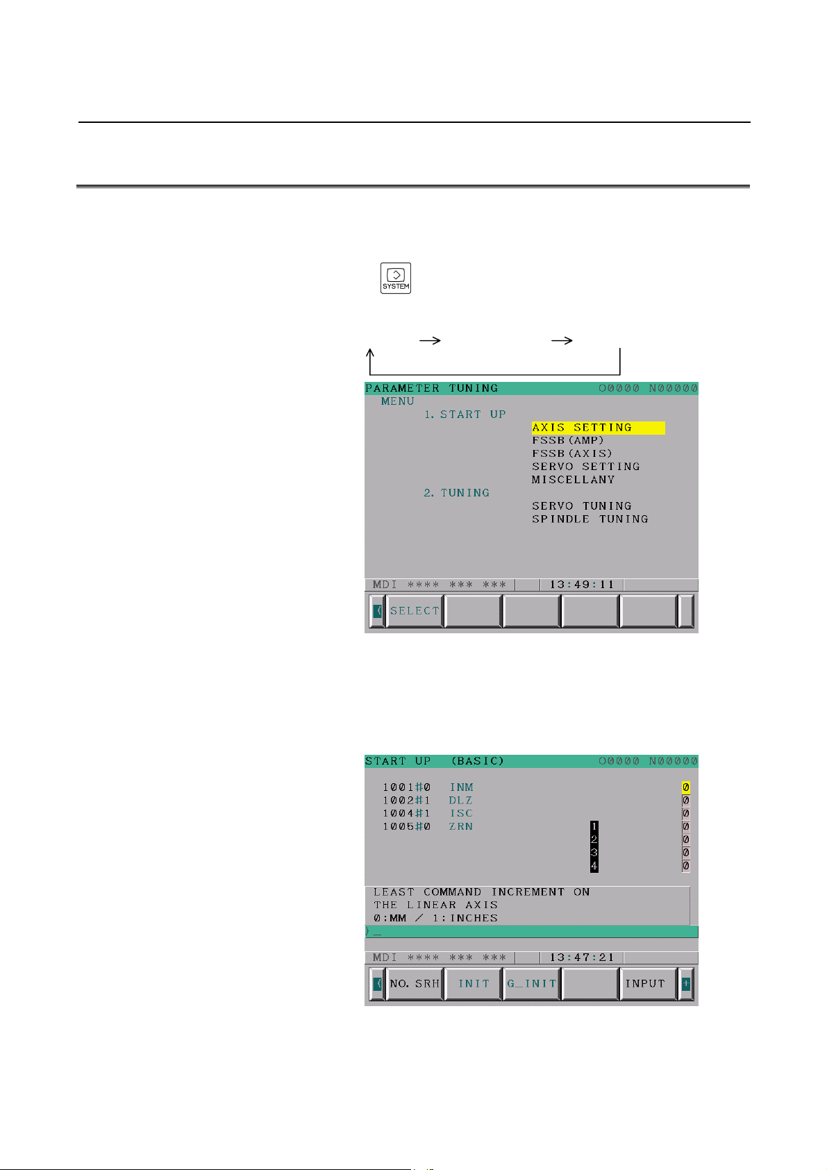
(1) Preparation
Switch on the NC in an emergency stop state.
Enable parameter writing (PWE = 1).
Press the
TUNING screen (parameter set supporting screen) appears.
PARAMETER DIAGNOSTIC PARAMETER TUNING
Press soft key [(OPRT)], move the cursor to the AXIS SETTING item,
and press [SELECT] to display the START UP (parameter setting)
screen (Fig. 1.1 (b)). This screen is used to make the parameter
settings shown below.
function key several times until the PARAMETER
Fig. 1.1 (a) PARAMETER TUNING screen
Fig. 1.1 (b) START UP screen
- 2 -
Page 9
B-64114EN-1/011.INITIALIZATION OF THE NC PARAMETERS RELATED TO AXIS SETTINGS
(2) Initialization
Parameters are initialized on the START UP screen. On the START
UP screen, parameters are classified into several groups, each of
which is displayed on successive pages.
Initialization is made for each group. The procedure is described
below.
NOTE
1 Since "Example of setting" in the following
descriptions indicates reference values for
initialization.
Determine the best setting based on the
characteristics and usage of the machine.
2 "Example of setting" in the following descriptions
assumes an increment system of IS-B (bit 1 of
parameter No. 1004 is 0) and metric input (bit 2 of
parameter No. 0000 is 0).
3 For details on the individual parameters, refer to
the parameter manual.
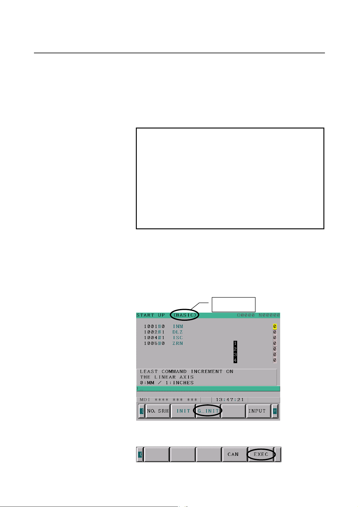
<1> BASIC group
<1>-1 Setting the standard values
The standard values are set for the parameters in the BASIC group.
Press the PAGEUP or PAGEDOWN key several times until the
BASIC group screen appears and then press soft key [G_INIT].
Group name
The message "DO YOU SET INIT-VALUE" appears.
Press soft key [EXEC].
- 3 -
Page 10

1.INITIALIZATION OF THE NC PARAMETERS RELATED TO AXIS SETTINGSB-64114EN-1/01
This sets the standard values for the parameters in the BASIC group.
NOTE
1 The parameters on all pages in the group are set to
the standard values regardless of the page on
which [G_INIT] is selected.
2 Some parameters have no standard value. The
values of these parameters do not change even
after setting the standard values.
3 Setting the standard values may issue "Alarm No.
000 (PLEASE TURN OFF POWER)" the alarm
screen appears, but it is not necessary to turn off
the power. Display the START UP screen again as
described in "(1) Preparation" and then proceed to
the next procedure.
<1>-2 Setting parameters for additional axes
When no additional axes are present, proceed to Step <<1>-3 Setting
parameters without the standard values>
NOTE
1 The standard value settings made in Step <<1>-1
Setting the standard values> includes parameters
for setting the standard value only for the basic
axes (M series: 1st to 3rd axes, T series: 1st to 2nd
axes).
In Step <<1>-2 Setting the parameters for
additional axes>, the additional axis (M series: 4th
and subsequent axes, T series: 3rd and
subsequent axes) portions of the parameters are
set manually.
2 When a parameter number is entered and then soft
key [NO.SRH] is pressed, the cursor moves to the
specified parameter.
Set the following parameters related to additional axes.
1020 Program axis name for each axis Each axis
M series T series
Axis
name
Setting
U 85 A 65 Y 89 B 66
V 86 B 66 A 65 C 67
W 87 C 67
Axis
name
Setting
Axis
name
Setting
Axis
name
Setting
- 4 -
Page 11

B-64114EN-1/011.INITIALIZATION OF THE NC PARAMETERS RELATED TO AXIS SETTINGS
1022 Setting of each axis in the basic coordinate system Each axis
Set value Meaning
0 Neither the basic three axes nor a parallel axis
5 Axis parallel to the X axis
6 Axis parallel to the Y axis
7 Axis parallel to the Z axis
<1>-3 Setting the parameters without the standard values
NOTE
1 Some parameters are not set to the standard value
even after setting the standard value in Step
<<1>-1 Setting the standard values>.
These parameters are set manually in Step <<1>-3
Setting parameters without the standard values>.
2 When a parameter number is entered and then soft
key [NO.SRH] is pressed, the cursor moves to the
specified parameter.
• Set the type of each axis, linear or rotation.
Setting linear or rotation axis.
1006#0
• Set the metric system or inch system as the liner axis output unit.
1001#0
• The least input increment and least command increment are set.
1004#1
IS-B 0.001mm, 0.001deg, or 0.0001inch
IS-C 0.0001mm, 0.0001deg, or 0.00001inch
• Set the servo axis number as shown below.
1023 Number of the servo axis Each axis
1st axis (X axis) 1 1st axis (X axis) 1
2nd axis (Y axis) 2 2nd axis (Z axis) 2
3rd axis (Z axis) 3 3rd axis 3
4th axis 4 4th axis 4
0: Linear axis
1: Rotation axis
Least command increment on the linear axis
0: In mm (metric system machine)
1: In inches (inch system machine)
Setting least input increment and least command
increment
0: IS-B
1: IS-C
Least input increment and least command increment
M series T series
Each axis
All axes
All axes
- 5 -
Page 12

1.INITIALIZATION OF THE NC PARAMETERS RELATED TO AXIS SETTINGSB-64114EN-1/01
• Specify whether the position detector is an absolute position
detector.
Position detector
1815#5
0: Other than absolute position detector
1: Absolute position detector
Each axis
• When using reference position return without DOG, set the
following parameters.
When using reference position return without DOG for all axes
Function setting the reference position without DOG
1002#1
0: Disabled
1: Enabled (enabled for all axes)
All axes
When using reference position return without DOG for some
axes
Function setting the reference position without DOG
1005#1
0: Disabled (disabled for each axis)
1: Enabled (enabled for each axis)
Each axis
• Set the following parameters.
Parameter No. Example of setting Description Type
1825 5000 Servo loop gain Each axis
1826 10 In–position width Each axis
1828 7000
Positioning deviation
limit in movement
Each axis
<2> COORDINATE group
<2>-1 Setting the standard values
The standard values are set for the parameters in the COORDINATE
group.
Follow a procedure similar to Step <<1>-1 Setting the standard
values> in <<1> BASIC group>
<2>-2 Setting the parameters without the standard values
Set the following parameters.
Parameter
No.
1240
1241
1320
1321
Description Type
Coordinate value of the first reference
position on in the machine coordinate
system
Coordinate value of the second
reference position in the machine
coordinate system
Coordinate value of stored stroke
check 1 in the positive direction
Coordinate value of stored stroke
check 1 in the negative direction
Each
axis
Each
axis
Each
axis
Each
axis
Unit of
data
Increment
system
Increment
system
Increment
system
Increment
system
- 6 -
Page 13

B-64114EN-1/011.INITIALIZATION OF THE NC PARAMETERS RELATED TO AXIS SETTINGS
<3> FEED RATE group
<3>-1 Setting the standard values
The standard values are set for the parameters in the FEED RATE
group.
Follow a procedure similar to Step <<1>-1 Setting the standard
values> in <<1> BASIC group>
<3>-2 Setting the parameters without the standard values
Set the following parameters.
Parameter
No.
1410 1000 Dry run rate All axes
1420 8000 Rapid traverse rate Each axis
1421 1000 F0 rate of rapid traverse override Each axis
1422 10000 Maximum cutting feedrate All axes
1423 1000 Feedrate in jog feed Each axis
1424 5000 Manual rapid traverse rate Each axis
1425 150
Example of
setting
Description Type
FL rate of the reference position
return
Each axis
<4> ACC./DEC. (Acceleration/Deceleration) group
Set the following parameters.
Parameter
No.
1620 100
1622 32
1624 100
Example of
setting
Description Type
Time constant used for linear
acceleration/deceleration in rapid
traverse
Time constant
aceeleration/deceleration in
cutting feed
Time constant
aceeleration/deceleration in jog
feed
Each axis
Each axis
Each axis
- 7 -
Page 14

1.INITIALIZATION OF THE NC PARAMETERS RELATED TO AXIS SETTINGSB-64114EN-1/01
(3) Restarting the NC
Turn off and back on the NC power. This completes the initialization
of the NC parameters related to axis settings.
NOTE
1 To operate the servo axis, it is necessary to set the
following signals in addition to the above
parameters. For details on each signal, refer to the
Connection Manual (Function).
Address Symbol Signal name
G008#0 *IT Interlock signal for all
axes
G008#4 *ESP Emergency stop signal
G008#5 *SP Feed hold signal
G010,G011 *JV Manual feedrate
override signal
G012 *FV Feedrate override signal
G114 *+L1 to *+L8 Overtravel signals
G116 *-L1 to *-L8 Overtravel signals
G130 *IT1 to *IT8 Interlock signal for each
axis
2 Manual Setting 1 is used as the FSSB setting
method in this manual. When using Manual Setting
1, it is not necessary to use the FSSB (AMP) and
FSSB (AXIS) items on the parameter setting aid
screen.
In Manual Setting 1, restrictions are imposed on
the functions and settings that can be used. The
restrictions and details on FSSB settings, refer to
the FSSB settings section in the Connection
Manual (Function).
- 8 -
Page 15

B-64114EN-1/011.INITIALIZATION OF THE NC PARAMETERS RELATED TO AXIS SETTINGS
1.2 NC PARAMETERS RELATED TO AXIS SETTINGS
This section lists the parameters to be set during initialization of the
NC parameters related to axis settings. For details on each parameter,
refer to the parameter manual.
Group Parameter No. Summary
Least command increment on the linear axis
BASIC
COORDINATE
FEED RATE
ACC./DEC.
1001#0
1002#1
1004#1
1005#1
1006#0
1020 Program axis name for each axis
1022 Setting of each axis in the basic coordinate system
1023 Number of the servo axis
1815#5
1825 Servo loop gain for each axis
1826 In–position width for each axis
1828 Positioning deviation limit in movement for each axis
1240
1241
1320 Coordinate value of stored stroke check 1 in the positive direction
1321 Coordinate value of stored stroke check 1 in the negative direction
1410 Dry run rate
1420 Rapid traverse rate for each axis
1421 F0 rate of rapid traverse override for each axis
1422 Maximum cutting feedrate (common to all axes)
1423 Feedrate in jog feed for each axis
1424 Manual rapid traverse rate for each axis
1425 FL rate of the reference position return for each axis
1620
1622
1624 Time constant aceeleration/deceleration in jog feed for each axis
0: In mm (metric system machine)
1: In inches (inch system machine)
Function setting the reference position without DOG
0: Disabled
1: Enabled (enabled for all axes)
Setting least input increment and least command increment
0: IS-B
1: IS-C
Function setting the reference position without DOG
0: Disabled (disabled for each axis)
1: Enabled (enabled for each axis)
Setting linear or rotation axis.
0: Linear axis
1: Rotation axis
Position detector
0: Other than absolute position detector
1: Absolute position detector
Coordinate value of the first reference position on in the machine
coordinate system for each axis
Coordinate value of the second reference position in the machine
coordinate system for each axis
Time constant used for linear acceleration/deceleration in rapid
traverse for each axis
Time constant aceeleration/deceleration in cutting feed for each
axis
- 9 -
Page 16

2.INITIALIZATION OF SERVO PARAMETERS B-64114EN-1/01
2 INITIALIZATION OF SERVO
PARAMETERS
- 10 -
Page 17

B-64114EN-1/01 2.INITIALIZATION OF SERVO PARAMETERS
A
(
f
g
2.1 PARAMETER INITIALIZATION FLOW
Make the following settings on the servo setting screen and servo
adjustment screen.
In emergency stop state, switch on NC.
Initialization bits
Motor No.
MR
CMR
Move direction
Reference counter
Use the separate detector.
No.1815#1=1)
Set flexible feed gear. Set flexible feed gear.
Number of velocity pulses 8192
Number of position pulses Ns
00000000
See (2)-<2> in Sec. 2.2.
00000000
See (2)-<4> in Sec. 2.2.
111 (Clockwise as viewed from detector)
-111 (Counterclockwise as viewed from detector)
See (2)-<8> in Sec. 2.2.
Which system is being used?
See (2)-<5> in Sec. 2.2.
Number of velocity pulses 8192
Number of position pulses 12500
Semi-closed Closed loop
For the phase A/B separate
detector and serial linear scale:
Ns: Number of feedback pulses per motor
revolution, received from the separate
detector
End of parameter settin
Turn powerof
- 11 -
Page 18

2.INITIALIZATION OF SERVO PARAMETERS B-64114EN-1/01
2.2 PARAMETER SETTING PROCEDURE
(1) Preparation
Switch on the NC in an emergency stop state.
Enable parameter writing (PWE = 1).
Press the
function key several times until the PARAMETER
TUNING screen (parameter set supporting screen) appears.
PARAMETER DIAGNOSTIC PARAMETER TUNING
Fig. 2.2 (a) PARAMETER TUNING screen
Press soft key [(OPRT)], move the cursor to the SERVO SETTING
item, and press [SELECT] to display the Servo setting screen (Fig. 2.2
(b)). When the screen appears, move the cursor to the item to be set
and directly enter data.
Servo set
<1>
INITIAL SET BITS
<2>
Motor ID No.
<3>
AMR
<4>
CMR
<5>
Feed gear N
<5>
(N/M) M
<6>
Direction Set
<7>
Velocity Pulse No.
<7>
Position Pulse No.
<8>
Ref. counter
Fig. 2.2 (b) Servo setting screen
X axis
00000000
00000000
258
100
111
8192
12500
10000
2
1
Z axis
00000000
258
00000000
2
1
100
111
8192
12500
10000
- 12 -
Page 19

B-64114EN-1/01 2.INITIALIZATION OF SERVO PARAMETERS
(2) Initialization
Start initialization. Set <1> to <8> on the servo setting screen and turn
off and back on the CNC power.
For full-closed systems, first set the following parameter.
#7 #6 #5 #4 #3 #2 #1 #0
1815 OPTx
↑ Set 1.
OPTx(#1) The separate position detector is:
0: Not to be used ← For semi-closed systems
1: To be used ← For full-closed systems
<1> Initialization bit
Initialization bit 00000000
When initialization is completed successfully, DGPR (#1) is set to 1
and PRMC (#3) is set to 1 automatically the next time the CNC power
is turned off and back on.
<2> Motor ID No. setting
Specify the motor ID number.
Select the motor number of the αis/αi/βis series servo motor to be
used in the following table. The motor number consists of a motor
model, a motor drawing number (4-digit number in the middle of
A06B-****-B***), and the maximum current value of the driving
amplifier.
i
Motor model
α12/4000is
α22/4000is
α30/4000is
α40/4000is
α12/3000i
α22/3000i
α30/3000i
α40/3000i
α40/3000i FAN
i
s/
series servo motor
α
α
α2/5000is
α4/5000is
α8/4000is
α1/5000i
α2/5000i
α4/4000i
α8/3000i
Motor
specification
0212 20A 262
0215 40A 265
0235 80A 285
0238 80A 288
0265 160A 315
0268 160A 318
0272 160A 322
0202 20A 252
0205 20A 255
0223 40A 273
0227 40A 277
0243 80A 293
0247 80A 297
0253 160A 303
0257 160A 307
0258 160A 308
Maximum current
value of the
driving amplifier
Motor type No.
- 13 -
Page 20

2.INITIALIZATION OF SERVO PARAMETERS B-64114EN-1/01
i
s series servo motor
β
Motor model
β0.2/
β0.3/
β0.4/
β0.5/
β1/
5000
β2/
4000
β4/
4000
β8/
3000
β12/
3000
β22/
2000
5000
5000
5000
5000
specification
is
is
is
is
is
is
is
is
is
is
Motor
0210 4A 260
0211 4A 261
0114 20A 280
0115 20A 281
0116 20A 282
0061
0063
0075
0078 40A 272
0085 40A 274
Maximum current
value of the
driving amplifier
20A 253
40A 254
20A 256
40A 257
20A 258
40A 259
Motor type No.
<3> AMR setting
This parameter corresponds to the number of poles of the servo motor.
For the αis/αi/βis motor, be sure to set 00000000.
αis/αi/βis servo motor
00000000
<4> CMR setting
Set CMR with the scale of a distance the NC instructs the machine to
move.
Setting value = (Command unit / Detection unit) × 2
CMR 2
Usually, set CMR with 2, because command unit = detection unit.
<5> Flexible feed gear setting
Set the parameters of the flexible field gear.
Flexible feed gear (numerator) N
Flexible feed gear (denominator) M
- 14 -
Page 21

B-64114EN-1/01 2.INITIALIZATION OF SERVO PARAMETERS
<5>-1 Semi-closed feedback loop
Examples of flexible field gear settings (gear ratio: 1 to 1)
Ball screw lead (N/M) Detection
unit
1µm 6/1000 8/1000 10/1000 12/1000 16/1000 20/1000
0.5 µm 12/1000 16/1000 20/1000 24/1000 32/1000 40/1000
0.1 µm 60/1000 80/1000 100/1000 120/1000 160/1000 200/1000
6mm 8mm 10mm 12mm 16mm 20mm
(Expression of calculation of parameters)
Set the pulse skipping rate assuming that the number of pulses
generated per motor turn is 1000000, regardless of the type of the
pulse coder.
Flexible feed
gear
Number of pulses
required per motor turn
Flexible feed gear
Necessary position feedback
pulses per motor revolution
1,000,000 fraction)
1,000,000 pulses generated
per motor turn (fixed)
(as irreducible
NOTE
The maximum specifiable value (after reduction) of
the flexible field gear is 32767 for both the
numerator and denominator.
Example of setting (1)
If the ball screw used in direct coupling has a lead of 10 mm/rev and
the detection unit is 1 µm
The number of pulses generated per motor turn (10 mm) is:
10/0.001 = 10,000 (pulses)
Numerator of flexible field gear 10,000 1
Denominator of flexible field gear
Example of setting (2)
If the gear reduction ratio between the rotation axis motor and table is
10:1 and the detection unit is 1/1000 degrees
• The table rotates through 360/10 (=36) degrees when the motor
makes one turn.
• Since the detection unit is 1/1000 degrees, the number of position
pulses generated per motor turn is:
(36 degrees per motor turn)/(Detection unit of 1/1000 degrees) =
36000 pulses
Therefore, the flexible gear setting is as shown below.
Numerator of flexible field gear 36,000 36
Denominator of flexible field gear
=
=
1,000,000
1,000,000
=
100
=
100
- 15 -
Page 22

2.INITIALIZATION OF SERVO PARAMETERS B-64114EN-1/01
<5>-2 Full-closed feedback loop
Example of flexible field gear settings (N/M)
Scale resolution Detection
unit
1 µm 1/1 1/2 1/10 1/20
0.5 µm - 1/1 1/5 1/10
0.1 µm - - 1/1 1/2
1 µm 0.5 µm 0.1 µm 0.05 µm
(Expression of calculation of parameters)
Set the pulse skipping rate for the number of scale output pulses
Flexible feed
gear
Scale output pulses Pulses for position control
(detection unit)
Flexible feed gear
Pulses for position control
(as irreducible
Scale output pulses fraction)
Example of setting
To detect a distance of 1 µm using a 0.5 µm scale, set the following:
• The number of scale output pulses for movement of 1 µm is:
1 µm/0.5 µm = 2
• Since the detection unit is 1 µm, the number of pulses used for
position control is 1.
Therefore, the flexible field gear setting is:
Numerator of flexible field gear 1 pulse 1
Denominator of flexible field gear
=
2 pulses
=
2
<6> Motor rotation direction setting
111 Clockwise as viewed from the Pulsecoder
-111 Counterclockwise as viewed from the Pulsecoder
When the direction is
clockwise as viewed
from the pulsecoder,
set -111.
- 16 -
FANUC
When the direction is
counterclockwise as
viewed from the
pulsecoder, set 111.
Page 23

B-64114EN-1/01 2.INITIALIZATION OF SERVO PARAMETERS
<7> Specify the number of velocity pulses and the number of position pulses.
<7>-1 Semi-closed feedback loop
Number of velocity pulses 8192 (Fixed value)
Number of position pulses 12500 (Fixed value)
<7>-2 Full-closed feedback loop (Parallel type or Serial liner scale)
Number of velocity pulses 8192 (Fixed value)
Number of position pulses
Set the number of pulses fed back from the separate detector (before
processing of the flexible field gear) when the motor rotates one turn.
Example 1 :
If the ball screw used in direct coupling has a lead of 10 mm and
the separate detector used has a resolution of 0.5 µm (= 0.0005
mm) per pulse
Number of
feedback pulses
per motor 1rev.
==
Therefore, the setting of the number of position pulses is 20000.
When the calculated number of position pulses is greater than
32767, set the number of position pulses by using the position
pulse conversion factor (No. 2185) to multiply the parameter of
the number of position pulses by the parameter of the conversion
factor.
2024 Number of position pulses
2185 Position pulse conversion factor
Example 2 :
If the ball screw used in direct coupling has a lead of 16 mm and
the separate detector used has a resolution of 0.1 µm (= 0.0001
mm) per pulse
Number of
feedback pulses
per motor 1rev.
==
Number of feedback pulses from the
scale per motor turn
Ball screw lead =
10mm
20000
Scale resolution
= 0.0005mm
Ball screw lead =
16mm
160,000
Scale resolution
= 0.0001mm
- 17 -
Page 24

2.INITIALIZATION OF SERVO PARAMETERS B-64114EN-1/01
Therefore, the setting of the number of position pulses is 160000.
The value exceeds 32767 and cannot be entered as the number of
position pulses on the servo setting screen.
In this case, make settings as shown below.
No.2024 = 16,000
No.2185 = 10
(When the value of No. 2024 multiplied by the value of No. 2185
is 160000, another setting is allowed.)
<8> Reference counter setting
Specify the reference counter.
The reference counter is used in making a return to the reference
position by a grid method.
<8>-1 Semi-closed feedback loop
Count on the reference
counter
Example of setting
αi/βi Pulsecoder and semi-closed loop (1-µm detection)
Ball screw lead
(mm/revolution)
10
20
Number of position pulses corresponding to a
=
single motor revolution
Necessary number of
position pulses
(pulse/revolution)
10000
20000
Reference
counter
10000
20000
Grid width
(mm)
10
20
<8>-2 Full-closed feedback loop
Reference counter
setting
Example of setting
Example 1 :
When the Z-phase interval is 50 mm and the detection unit is 1
µm: Reference counter setting = 50,000/1 = 50,000
Example 2 :
When a rotation axis is used and the detection unit is 0.001°:
Reference counter setting = 360/0.001 = 360,000
Example 3 :
When a linear scale is used and a single Z phase exists:
Set the reference counter to 10000, 50000, or another round
number.
Turn off and back on the NC power. This completes the initialization
of the servo parameters.
Z-phase (reference-position) interval divided by
=
the detection unit
- 18 -
Page 25

B-64114EN-1/01 3.INITIALIZATION OF THE OTHER NC PARAMETERS
3 INITIALIZATION OF THE OTHER NC
PARAMETERS
- 19 -
Page 26
3.INITIALIZATION OF THE OTHER NC PARAMETERS B-64114EN-1/01
3.1 INITIALIZATION PROCEDURE
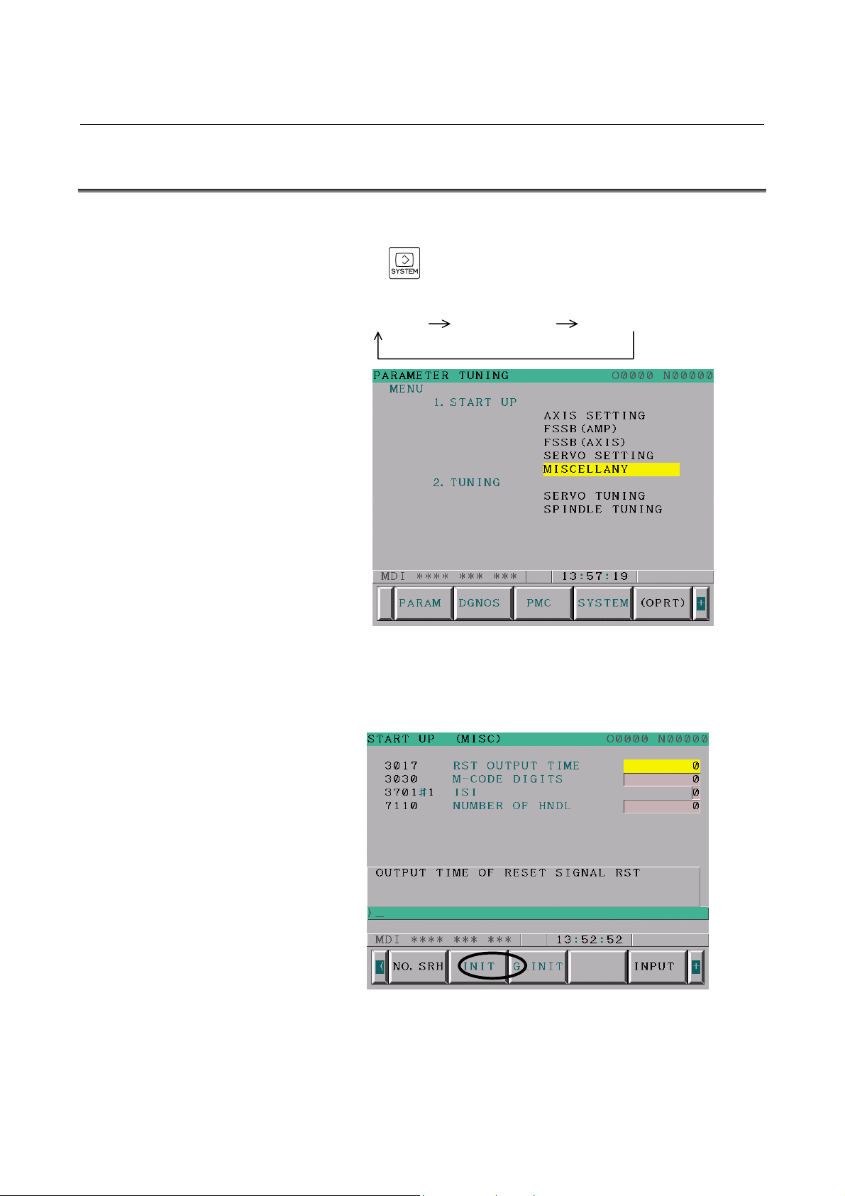
Switch on the NC in an emergency stop state.
Enable parameter writing (PWE = 1).
Press the
TUNING screen (parameter set supporting screen) appears.
PARAMETER DIAGNOSTIC PARAMETER TUNING
Press soft key [(OPRT)], move the cursor to the MISCELLANY item,
and press [SELECT] to display the parameter setting (START UP
(MISC)) screen (Fig. 3.1 (b)).
function key several times until the PARAMETER
Fig. 3.1 (a) PARAMETER TUNING screen
Fig. 3.1 (b) START UP (MISC) screen
Press soft key [G_INIT].
The message "DO YOU SET INIT-VALUE" appears.
- 20 -
Page 27

B-64114EN-1/01 3.INITIALIZATION OF THE OTHER NC PARAMETERS
Press soft key [EXEC].
This completes the initialization of the other servo parameters.
- 21 -
Page 28

4.PARAMETERS RECOMMENDED TO BE SET B-64114EN-1/01
4 PARAMETERS RECOMMENDED TO BE
SET
(1) Parameters related to high-speed and high-precision operations
This section describes the parameters recommended to be set for
the AI advanced preview control specification and AI contour
control specification.
The parameter list also shows the servo-related parameters.
(2) Minimum servo parameters required to be adjusted
This section describes the minimum servo parameters required to
be adjusted based on the machine characteristics.
NOTE
First enter the standard settings.
To reduce the machining time, use a parameter for
speed priority I. To further reduce the machining
time, use a parameter for speed priority II.
When using a speed priority parameter, however,
the machining precision decreases.
- 22 -
Page 29

B-64114EN-1/01 4.PARAMETERS RECOMMENDED TO BE SET
4.1 PARAMETERS RELATED TO HIGH-SPEED AND
HIGH-PRECISION OPERATIONS
[Functions related to high-speed and high-precision operations]
High-speed and
high-precision functions
Series 0i Mate-MC
Series 0i-MC
Acceleration/deceleration
before interpolation
Type
Velocity control
Automatic corner
deceleration
Arc radius-based velocity
control
Acceleration-based velocity
control
AI advance preview
control
(AI-APC)
○
○ ○
Linear
Linear/Bell-shaped
○ ○
○ ○
○ ○
*1 Options are required to perform bell-shaped
acceleration/deceleration before interpolation and
bell-shaped acceleration/deceleration after cutting
feed interpolation.
AI contour control
(AICC)
(*1)
- 23 -
Page 30

4.PARAMETERS RECOMMENDED TO BE SET B-64114EN-1/01
(1) AI advanced preview control
- Parameters to be set based on the machine type
Standard setting value
Parameter No.
1432 - - - Maximum cutting feedrate (mm/min) for each axis
1620 - - -
1621 - - -
1730 3250 5150 7275 Feedrate upper limit (mm/min) for arc radius R
1731 5000 5000 5000
1732 100 100 100
1768 24 24 24
1770 10000 10000 10000
1771 240 80 40
1783 400 500 1000
1784 - - -
1785 320 112 56
Standard
setting
Speed
priority I
Speed
priority II
Time constant (ms) for linear-shaped Acc./Dec. in
rapid-traverse for each axis
Time constant T2 (ms) for bell-shaped Acc./Dec. in
rapid-traverse for each axis
Arc radius R (1
upper limit
Arc radius-based feedrate clamp lower speed limit
(mm/min)
Time constant (ms) for Acc./Dec. after cutting feed
interpolation
Maximum cutting feedrate (mm/min) during Acc./Dec.
before interpolation
Time (ms) allowed before a maximum cutting feedrate
during Acc./Dec. before interpolation is reached
Allowable speed difference (mm/min) in
acceleration-dependent on speed difference at corners
Speed (mm/min) at occurrence of overtravel alarm
To be specified according to the overrun distance at
overtravel
Parameter (ms) for determining an allowable
acceleration in determining acceleration-dependent
speed. The parameter is to be set with the time
allowed before a maximum cutting feedrate (parameter
No.1432) is reached.
A maximum cutting feedrate of 10000 mm/min is used
as the standard setting value.
Description
µm) for arc radius-based feedrate
- Parameters for which a fixed value is set
Parameter No.
1602#6,#3
Standard setting
value
#6,#3
1,0
Description
Acc./Dec. after interpolation is of a linear type (to be specified when
FAD is used)
- 24 -
Page 31

B-64114EN-1/01 4.PARAMETERS RECOMMENDED TO BE SET
- Parameters for which a fixed value is set (servo-related parameters)
Parameter No.
1825 5000 Position gain
2003 #3 1 Enables PI function
2003 #5 1 Enables backlash acceleration
2005 #1 1 Enables feed-forward
2006 #4 1 Uses the latest feedback data for velocity feedback.
2007 #6 1 Enables FAD (Fine Acc./Dec.)
2009 #7 1 Enables backlash acceleration stop
2016 #3 1 Enables variable proportional gain in the stop state
2017 #7 1 Enables velocity loop high cycle management function
2021 128 Load inertia ratio
2067 1166 TCMD filter
2069 50 Velocity feed-forward coefficient
2071 20 Period during which backlash acceleration remains effective
2082 5 (1µm detection)
2092 10000 Advanced preview (position) feed-forward coefficient
2107 150 Cutting load inertia ratio override (in % units)
2109 16 FAD time constant
2119 2 (1µm detection)
2202 #1 1 Cutting/rapid traverse velocity loop gain switching
2209 #2 1 Enables FAD of linear type.
Standard setting
value
Description
Timing at which the backlash acceleration is stopped (specified in
detection units)
For variable proportional gain function in the stop state : judgment level
for stop state (specified in detection units)
- Parameters to be set when using HRV3 (high-speed HRV current control)
To use servo HRV3 control, make the following settings.
Parameter No.
2013#0 1
2334 150 Current loop gain magnification for high-speed HRV current control
2335 200
Standard setting
value
In the G05.1Q1 command, high-speed HRV control (Current control
cycle 62.5
Velocity gain override (in % units) when high-speed HRV current control
is in use
µs)
Description
- 25 -
Page 32

4.PARAMETERS RECOMMENDED TO BE SET B-64114EN-1/01
(2) AI contour control
- Parameters to be set based on the machine type
Parameter
No.
1432 - - - Maximum cutting feedrate (mm/min) for each axis
1620 - - -
1621 - - -
1730 3250 5150 7275 Feedrate upper limit (mm/min) for arc radius R
1731 5000 5000 5000
1732 100 100 100
1768 24 24 24
1770 10000 10000 10000
1771 240 80 40
1772 64 48 32
1783 400 500 1000
1784 - - -
1785 320 112 56
Standard setting value
Standard
setting
Speed
priority I
Speed
priority II
Description
Time constant (ms) for linear-shaped Acc./Dec. in
rapid-traverse for each axis
Time constant T2 (ms) for bell-shaped Acc./Dec. in
rapid-traverse for each axis
Arc radius R (1
limit
Arc radius-based feedrate clamp lower speed limit
(mm/min)
Time constant (ms) for Acc./Dec. after cutting feed
interpolation
Maximum cutting feedrate (mm/min) during Acc./Dec.
before interpolation
Time (ms) allowed before a maximum cutting feedrate
during Acc./Dec. before interpolation is reached
Time constant (ms) for bell-shaped Acc./Dec. before
interpolation (portion with the time fixed)
Allowable speed difference (mm/min) in
acceleration-dependent on speed difference at corners
Speed (mm/min) at occurrence of overtravel alarm
To be specified according to the overrun distance at
overtravel
Parameter (ms) for determining an allowable
acceleration in determining acceleration-dependent
speed. The parameter is to be set with the time allowed
before a maximum cutting feedrate (parameter No.1432)
is reached.
A maximum cutting feedrate of 10000 mm/min is used as
the standard setting value.
µm) for arc radius-based feedrate upper
- Parameters for which a fixed value is set
Parameter
No.
1602#6,#3
1603#7 1
7050#5 1 To be set to the standard setting value.
7050#6 0 To be set to the standard setting value.
7052#0 0/1 To be set to 1 for the PMC and Cs axes.
Standard setting
value
#6,#3
1,0
1,1
Description
Acc./Dec. after interpolation is of a linear type (if bell-shaped Acc./Dec.
before interpolation is used)
Acc./Dec. after interpolation is of a bell-shaped type (if linear-shaped
Acc./Dec. before interpolation is used)
Acc./Dec. before interpolation is of a bell-shaped type (0: Linear-shaped
Acc./Dec. before interpolation)
- 26 -
Page 33

B-64114EN-1/01 4.PARAMETERS RECOMMENDED TO BE SET
- Parameters for which a fixed value is set (servo-related parameters)
Parameter No.
1825 5000 Position gain
2003 #3 1 Enables PI function
2003 #5 1 Enables backlash acceleration
2005 #1 1 Enables feed-forward
2006 #4 1 Uses the latest feedback data for velocity feedback.
2009 #7 1 Enables backlash acceleration stop
2016 #3 1 Enables variable proportional gain in the stop state
2017 #7 1 Enables velocity loop high cycle management function
2021 128 Load inertia ratio
2067 1166 TCMD filter
2069 50 Velocity feed-forward coefficient
2071 20 Period during which backlash acceleration remains effective
2082 5 (1µm detection)
2092 10000 Advanced preview (position) feed-forward coefficient
2107 150 Cutting load inertia ratio override (in % units)
2119 2 (1µm detection)
2202 #1 1 Cutting/rapid traverse velocity loop gain switching
Standard setting
value
Description
Timing at which the backlash acceleration is stopped (specified in
detection units)
For variable proportional gain function in the stop state : judgment
level for stop state (specified in detection units)
- Parameters to be set when using HRV3 (high-speed HRV current control)
To use servo HRV3 control, make the following settings.
Parameter No.
2013#0 1
2334 150 Current loop gain magnification for high-speed HRV current control
2335 200
Standard setting
value
In the G05.1Q1 command, high-speed HRV control (Current control
cycle 62.5
Velocity gain override (in % units) when high-speed HRV current
control is in use
µs)
Description
- 27 -
Page 34

4.PARAMETERS RECOMMENDED TO BE SET B-64114EN-1/01
4.2 SERVO PARAMETERS REQUIRED TO BE ADJUSTED
BASED ON THE MACHINE CHARACTERISTICS
This section describes the minimum servo parameters required to be
adjusted after the above parameter were set.
Make the following settings and then check the machine operation and
machining. If a problem occurs, change parameters as described in the
Adjustment field.
Parameters required to be adjusted to find the optimal value
Parameter
No.
2021 128
1825 5000 Position gain
2048 100 Backlash acceleration
Setting at
tuning start
Description Adjustment
Load inertia ratio (LDINT)
(velocity gain)
(Note 1)
When vibrations occur during movement of the axis,
reduce the setting to 128 → 64 → 0 in that order.
If vibrations do not disappear even when the load
inertia ratio is reduced to 0, reduce the position gain
(No. 1825) values for all axes to 5000
3000 in that order.
When a protrusion is found at the position where the
axis movement direction is reversed, increase the
setting in steps of 50.
When a depression is found, decrease the setting in
steps of 50.
→ 4000 →
NOTE
1 There is the following relationship between the load
inertia ratio and velocity loop gain (%).
Velocity loop gain (%)
= (1 + load inertia ratio/256) × 100
Example of conversion:
Velocity loop gain 150% -----Load inertia ratio 128
Velocity loop gain 200% -----Load inertia ratio 256
Velocity loop gain 250% -----Load inertia ratio 384
Velocity loop gain 300% -----Load inertia ratio 512
The servo guide (servo adjustment tool using PC) is useful to observe
the vibration state or a protrusion/depression during reversal of the
direction. Examples of observation of waveforms are shown below.
- 28 -
Page 35

B-64114EN-1/01 4.PARAMETERS RECOMMENDED TO BE SET
A
A
Change in the waveform depending on the load inertia ratio (velocity
gain) setting and position gain setting
dequate load inertia ratio (velocity gain)
Excessive load inertia ratio (velocity gain)
High-frequency vibrations are found.
dequate position gain
Motor speed
Torque c ommand
Low load inertia ratio (velocity gain)
The circle shape is not good and there are
big quadrant protrusions.
Motor speed
Torque c ommand
Excessively high position gain
Hunting is found during axis movement
Low position gain
There is a long delay in acceleration/deceleration.
- 29 -
Page 36

4.PARAMETERS RECOMMENDED TO BE SET B-64114EN-1/01
A
A
Change in the circle shape depending on the backlash acceleration
setting
dequate backlash acceleration
Excessive backlash acceleration
Depression occurs.
Small backlash acceleration
protrusion remains.
- 30 -
Page 37

B-64114EN-1/01 INDEX
INDEX
<A>
ACC./DEC. (Acceleration/Deceleration) group................7
AI advanced preview control ..........................................24
AI contour control...........................................................26
AMR setting....................................................................14
<B>
BASIC group.....................................................................3
<C>
CMR setting .................................................................... 14
COORDINATE group.......................................................6
<F>
FEED RATE group...........................................................7
Flexible feed gear setting ................................................14
Full-closed feedback loop .........................................16, 18
Full-closed feedback loop (Parallel type or Serial liner
scale).........................................................................17
Functions related to high-speed and high-precision
operations.................................................................. 23
PARAMETERS RECOMMENDED TO BE SET..........22
PARAMETERS RELATED TO HIGH-SPEED AND
HIGH-PRECISION OPERATIONS ......................... 23
Parameters required to be adjusted to find the optimal
value.......................................................................... 28
Parameters to be set based on the machine type........ 24, 26
Parameters to be set when using HRV3
(high-speed HRV current control).......................25, 27
<R>
Reference counter setting ................................................18
Restarting the NC..............................................................8
<S>
Semi-closed feedback loop.................................. 15, 17, 18
SERVO PARAMETERS REQUIRED TO BE
ADJUSTED BASED ON THE MACHINE
CHARACTERISTICS ..............................................28
Specify the number of velocity pulses and the number
of position pulses. .....................................................17
<I>
Initialization ................................................................ 3, 13
Initialization bit............................................................... 13
INITIALIZATION OF SERVO PARAMETERS........... 10
INITIALIZATION OF THE NC PARAMETERS
RELATED TO AXIS SETTINGS..............................1
INITIALIZATION OF THE OTHER NC
PARAMETERS ........................................................ 19
INITIALIZATION PROCEDURE .............................2, 20
<M>
Motor ID No. setting ....................................................... 13
Motor rotation direction setting.......................................16
<N>
NC PARAMETERS RELATED TO AXIS SETTINGS... 9
<P>
PARAMETER INITIALIZATION FLOW..................... 11
PARAMETER SETTING PROCEDURE.......................12
Parameters for which a fixed value is set .................. 24, 26
Parameters for which a fixed value is set
(servo-related parameters)...................................25, 27
i-1
Page 38

Page 39

Revision Record
FANUC Series 0i-MODEL C / Series 0i Mate-MODEL C START-UP MANUAL (B-64114EN-1)
Mar., 2005
01
Edition Date Contents Edition Date Contents
Page 40

 Loading...