

Page 1

GE Fanuc Automation
Computer Numerical Control Products
Series 0i-Model C
Series 0i-Mate Model C
Connection Manual (Function)
GFZ-64113EN-1/01 August 2004
Page 2

Warnings, Cautions, and Notes
as Used in this Publication
Warning notices are used in this publication to emphasize that hazardous voltages, currents,
temperatures, or other conditions that could cause personal injury exist in this equipment or
may be associated with its use.
In situations where inattention could cause either personal injury or damage to equipment, a
Warning notice is used.
Caution notices are used where equipment might be damaged if care is not taken.
GFL-001
Warning
Caution
Note
Notes merely call attention to information that is especially significant to understanding and
operating the equipment.
This document is based on information available at the time of its publication. While efforts
have been made to be accurate, the information contained herein does not purport to cover all
details or variations in hardware or software, nor to provide for every possible contingency in
connection with installation, operation, or maintenance. Features may be described herein
which are not present in all hardware and software systems. GE Fanuc Automation assumes
no obligation of notice to holders of this document with respect to changes subsequently made.
GE Fanuc Automation makes no representation or warranty, expressed, implied, or statutory
with respect to, and assumes no responsibility for the accuracy, completeness, sufficiency, or
usefulness of the information contained herein. No warranties of merchantability or fitness for
purpose shall apply.
©Copyright 2004 GE Fanuc Automation North America, Inc.
All Rights Reserved.
Page 3

B–64113EN–1/01
DEFINITION OF WARNING, CAUTION, AND NOTE
DEFINITION OF WARNING, CAUTION, AND NOTE
This manual includes safety precautions for protecting the user and preventing damage to the
machine. Precautions are classified into W arning and Caution according to their bearing on safety.
Also, supplementary information is described as a Note. Read the Warning, Caution, and Note
thoroughly before attempting to use the machine.
WARNING
Applied when there is a danger of the user being injured or when there is a danger of both the user
being injured and the equipment being damaged if the approved procedure is not observed.
CAUTION
Applied when there is a danger of the equipment being damaged, if the approved procedure is not
observed.
NOTE
The Note is used to indicate supplementary information other than Warning and Caution.
` Read this manual carefully, and store it in a safe place.
s–1
Page 4

Page 5

B–64113EN–1/01
PREFACE
PREFACE
This manual describes all the NC functions required to enable machine
tool builders to design their CNC machine tools. The following items are
explained for each function.
1. General
Describes feature of the function. Refer to Operator’s manual as
requied.
2. Signals
Describes names, functions, output conditions and addresses of the
signals required to realize a function.
3. Parameters
Describes parameters related with a function.
4. Alarms and messages
Lists the alarms and messages related with a function in a table.
5. Reference item
List the related items of the related manuals in a table.
A list of addresses of all signals and a list of signals are described in the
appendix of this manual. Refer to it as required.
p–1
Page 6
PREFACE
Series 0i–C
0i
Series 0i Mate–C
0i Mate
B–64113EN–1/01
Applicable models
Signal description
The models covered by this manual, and their abbreviations are :
Model name Abbreviation
FANUC Series 0i–TC 0i–TC
FANUC Series 0i–MC 0i–MC
FANUC Series 0i Mate–TC 0i Mate–TC
FANUC Series 0i Mate–MC 0i Mate–MC
For ease of understanding, the models are categorized as follows:
T series: 0i–TC, 0i Mate–TC
M series: 0i–TC, 0i Mate–TC
NOTE
Some functions described in this manual may not be applied
to some products.
For details, refer to the DESCRIPTIONS manual
(B–64112EN).
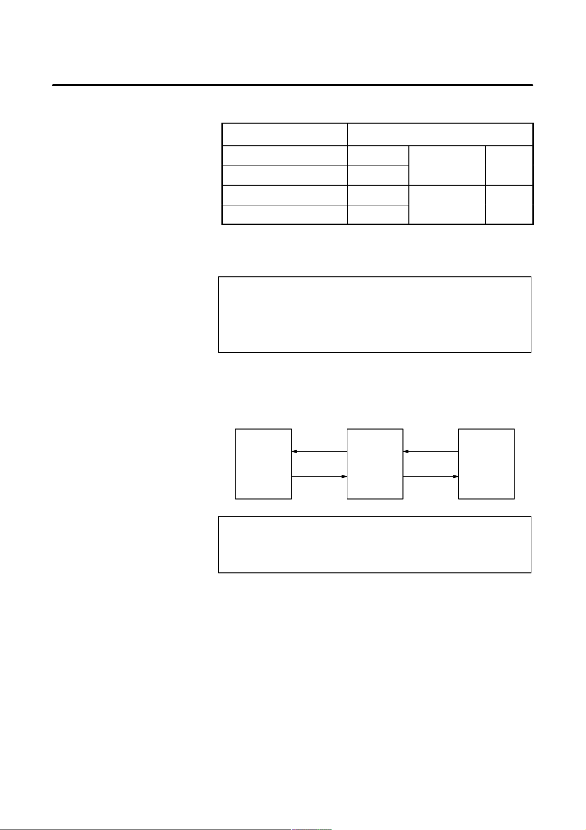
Relation of interface signals among the CNC, the PMC and the machine
tool is shown below:
G000–
CNC PMC
F000–
X000–
Y000–
Machine
tool
NOTE
For the signals, a single data number is assigned to 8 bits.
Each bit has a different meaning.
p–2
Page 7
B–64113EN–1/01
0 or 1
–127 to 127
In some parameters, signs are ig-
–127 to 127
In some parameters, signs are ig-
–32767 to 32767
–32767 to 32767
–99999999 to
–99999999 to
PREFACE
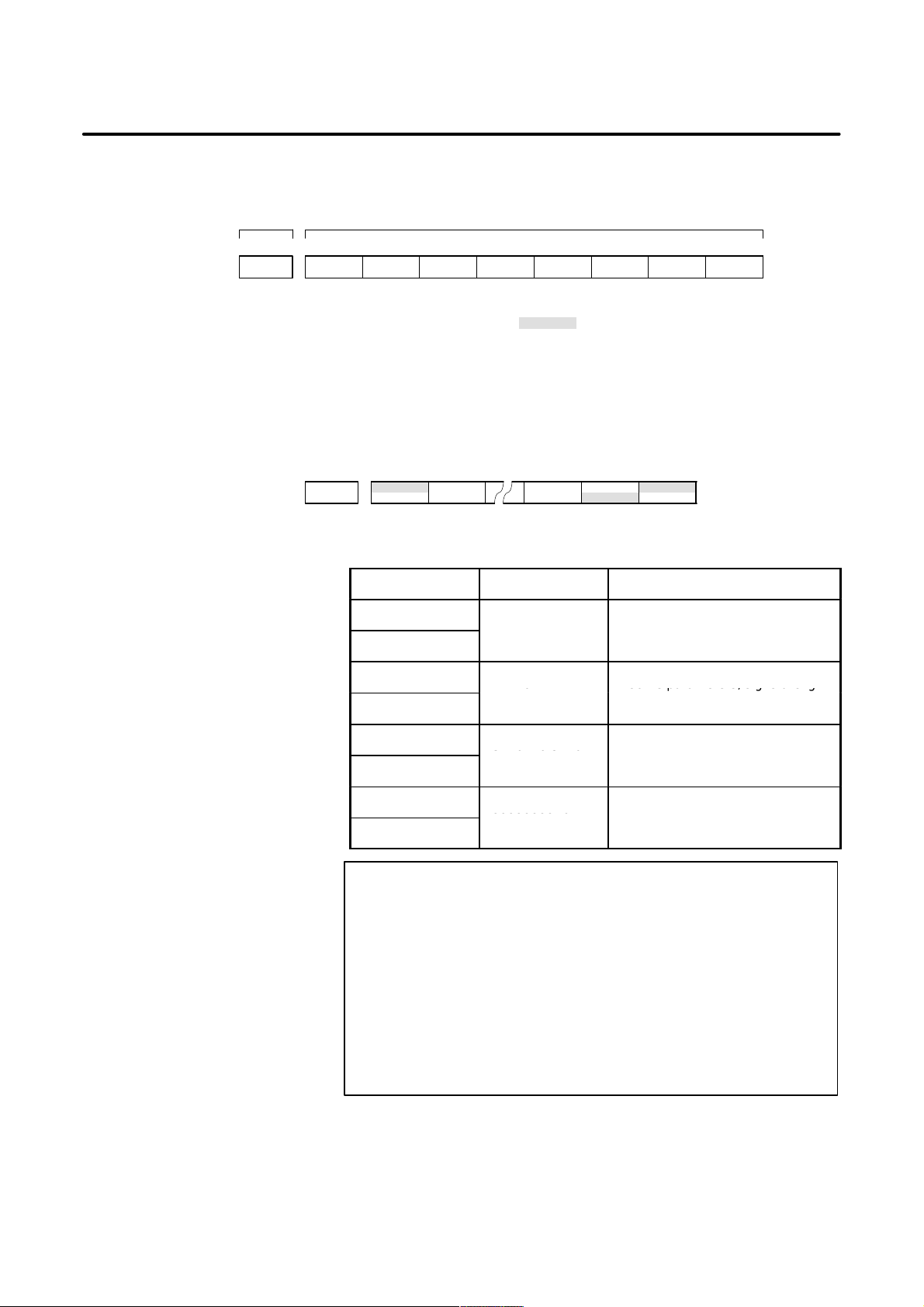
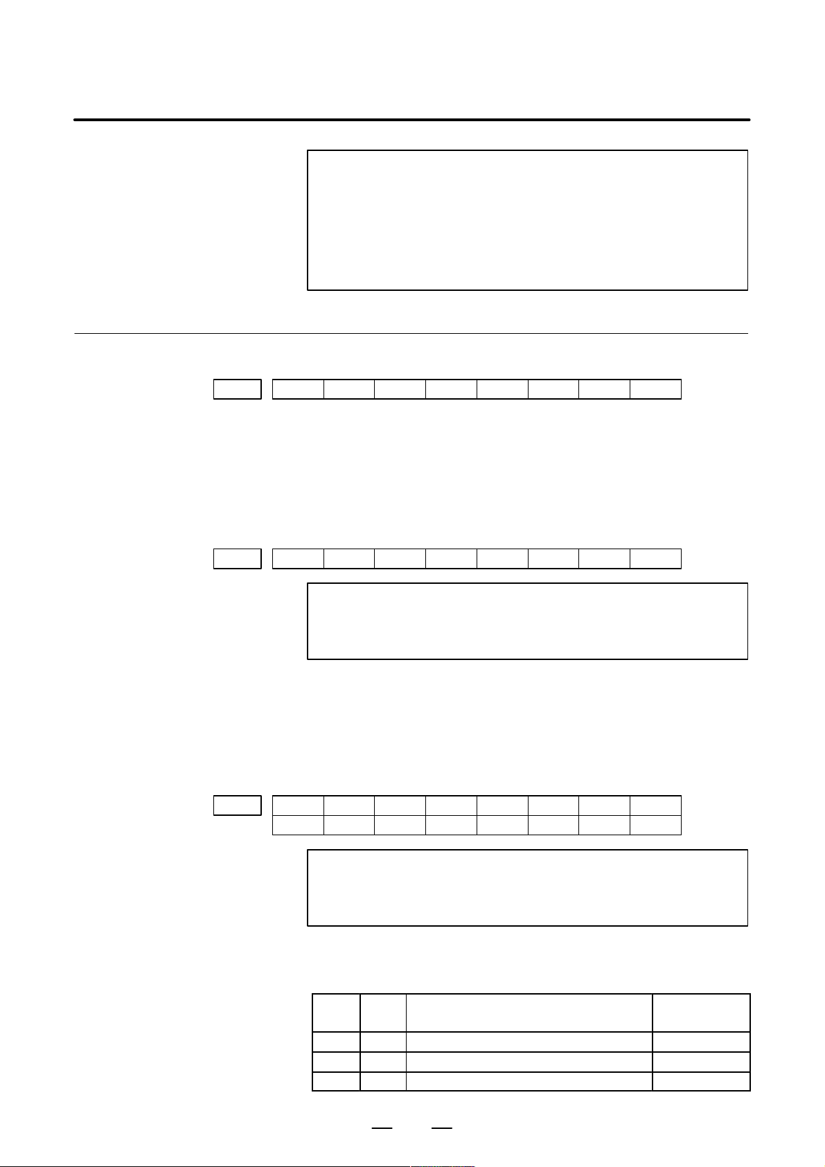
D Expression of signals
Parameter description
One address accommodates eight signals.
Symbol (#0 to #7 indicates bit position)Address
#7 #6 #5 #4 #3 #2 #1 #0
OPF000 SA STL SPL RWD
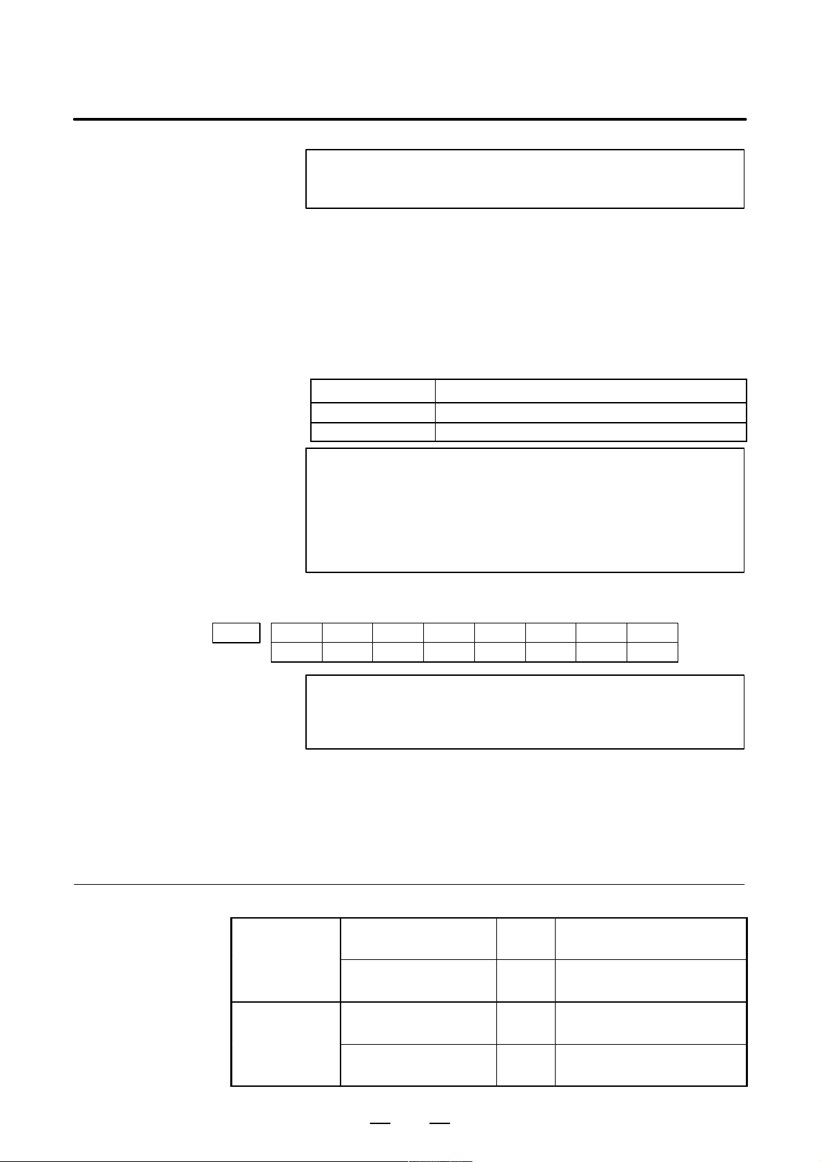
In an item where both T series and M series are described, some signals
are covered with shade ( ) in the signal address figure as shown
below. This means either T series or M series does not have this signal.
Upper part is for T series and lower part is for M series.
[Example 1]
Signal EXLM, ST is a common signal, STLK is for T series only and
RLSOT and RVS are for M series only.
#0
RVS
T series
M series
G007
#7
#6
EXLM
#2
ST
#1
STLKRLSOT
Parameters are classified by data type as follows :
Dta type Valid data range Remarks
Bit
Bit axis
Byte
Byte axis
Word
Word axis
2–word
2–word axis
0 to 255
0 to 65535
99999999
nored.
NOTE
1 For the bit type and bit axis type parameters, a single data
number is assigned to 8 bits. Each bit has a different
meaning.
2 The axis type allows data to be set separately for each
control axis.
3 The valid data range for each data type indicates a general
range. The range varies according to the parameters. For
the valid data range of a specific parameter, see the
explanation of the parameter.
p–3
Page 8

PREFACE
D Notation of bit type and
bit axis type parameters
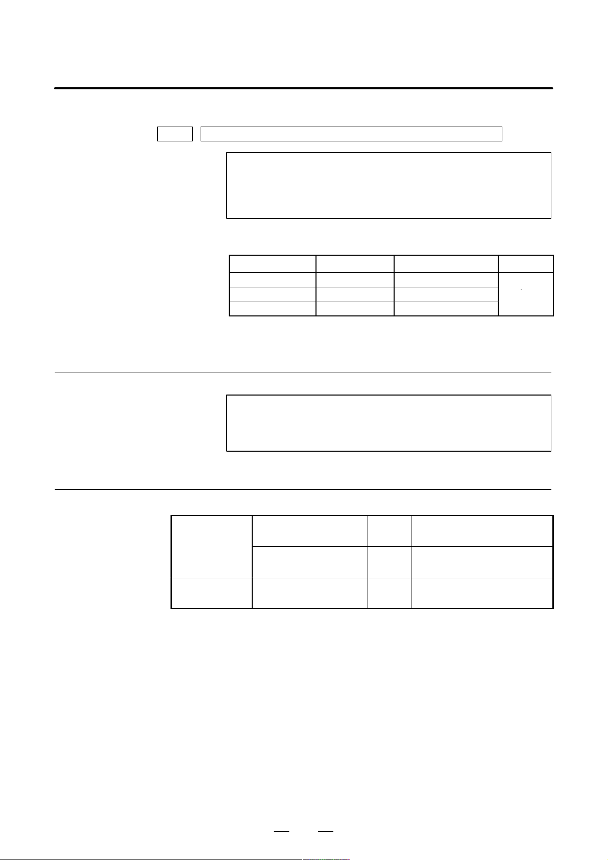
0000 SEQ INI ISO TVC
D Notation of parameters
other than bit type and
bit axis type
1023 Servo axis number of a specific axis
B–64113EN–1/01
Data (#0 to #7 indicates bit position)Data No.
#7 #6 #5 #4 #3 #2 #1 #0
DataData No.
NOTE
In an item where both T series and M series are described,
parameters having different meanings between the T series
and M series and parameters that are valid only for the T or
M series are indicated in two levels as shown below.
Parameters left blank are unavaliable.
[Example 1]
5010
[Example 2]
3401
[Example 3]
1450
Parameter 5010 has different meanigs for the T series and M series.
T ool nose radius compensation . . .
Cutter compensation C . . .
T series
M series
DPI is a parameter common to the M and T series, but GSB and GSC
are parameters valid only for the T series.
#7
GSC
#6
GSB
#0
DPI
DPI
T series
M series
The following parameter is provided only for the M series.
T series
F1 digit feed . . .
M series
p–4
Page 9

B–64113EN–1/01
PREFACE
Related manuals of
Series 0i–C/0i Mate–C
The following table lists the manuals related to Series 0i–C and 0i
Mate–C. This manual is indicated by an asterisk(*).
Manual name
DESCRIPTIONS B–64112EN
CONNECTION MANUAL (HARDWARE) B–64113EN
CONNECTION MANUAL (FUNCTION) B–64113EN–1 *
Series 0i–TC OPERATOR’S MANUAL B–64114EN
Series 0i–MC OPERA T OR’S MANUAL B–64124EN
Series 0i Mate–TC OPERA TOR’S MANUAL B–64134EN
Series 0i Mate–MC OPERA T OR’S MANUAL B–64144EN
MAINTENANCE MANUAL B–64115EN
P ARAMETER MANUAL B–64120EN
PROGRAMMING MANUAL
Macro Compiler/Macro Executor
PROGRAMMING MANUAL
FANUC MACRO COMPILER (For Personal Computer)
PROGRAMMING MANUAL
Specification
number
B–61803E–1
B–66102E
PMC
PMC Ladder Language PROGRAMMING MANUAL B–61863E
PMC C Language PROGRAMMING MANUAL B–61863E–1
Network
PROFIBUS–DP Board OPERA T OR’S MANUAL B–62924EN
Ethernet Board/DA T A SERVER Board
OPERA T OR’S MANUAL
FAST Ethernet Board/FAST DATA SERVER
OPERA T OR’S MANUAL
DeviceNet Board OPERA T OR’S MANUAL B–63404EN
OPEN CNC
FANUC OPEN CNC OPERATOR’S MANUAL
Basic Operation Package 1 (For Windows 95/NT)
FANUC OPEN CNC OPERATOR’S MANUAL
(DNC Operation Management Package)
B–63354EN
B–63644EN
B–62994EN
B–63214EN
p–5
Page 10

PREFACE
B–64113EN–1/01
Related manuals of
SERVO MOTOR αis/αi/βis
series
The following table lists the manuals related to SERVO MOTOR
αis/αi/βis series
Manual name
FANUC AC SER VO MOTOR αis/αi series
DESCRIPTIONS
FANUC AC SER VO MOTOR βis series
DESCRIPTIONS
FANUC AC SER VO MOTOR αis/αi/βis series
P ARAMETER MANUAL
FANUC AC SPINDLE MOT OR αi series
DESCRIPTIONS
FANUC AC SPINDLE MOT OR βis series
DESCRIPTIONS
FANUC AC SPINDLE MOT OR αi/βi series
P ARAMETER MANUAL
FANUC SER VO AMPLIFIER αi series
DESCRIPTIONS
FANUC SER VO AMPLIFIER βi series
DESCRIPTIONS
Specification
number
B–65262EN
B–65302EN
B–65270EN
B–65272EN
B–65312EN
B–65270EN
B–65282EN
B–65322EN
FANUC AC SER VO MOTOR αis/αi series
FANUC AC SPINDLE MOT OR αi series
FANUC SER VO AMPLIFIER αi series
MAINTENANCE MANUAL
FANUC AC SER VO MOTOR βis series
FANUC AC SPINDLE MOT OR βi series
FANUC SER VO AMPLIFIER βi series
MAINTENANCE MANUAL
B–65285EN
B–65325EN
Either of the following servo motors and the corresponding spindle can
be connected to the CNC covered in this manual.
D FANUC SERVO MOTOR αis series
D FANUC SERVO MOTOR βis series
This manual mainly assumes that the FANUC SERVO MOTOR αis
series of servo motor is used. For servo motor and spindle information,
refer to the manuals for the servo motor and spindle that are actually
connected.
p–6
Page 11

B–64113EN–1/01
Table of Contents
Volume 1
DEFINITION OF WARNING, CAUTION, AND NOTE s–1. . . . . . . . . . . . . . . . . . . . . . . . . . . . .
PREFACE p–1. . . . . . . . . . . . . . . . . . . . . . . . . . . . . . . . . . . . . . . . . . . . . . . . . . . . . . . . . . . . . . . . . . .
1. AXIS CONTROL 1. . . . . . . . . . . . . . . . . . . . . . . . . . . . . . . . . . . . . . . . . . . . . . . . . . . . . . . . . . . . . .
1.1 CONTROLLED AXES 2. . . . . . . . . . . . . . . . . . . . . . . . . . . . . . . . . . . . . . . . . . . . . . . . . . . . . . . . . . . . .
1.2 SETTING EACH AXIS 4. . . . . . . . . . . . . . . . . . . . . . . . . . . . . . . . . . . . . . . . . . . . . . . . . . . . . . . . . . . . .
1.2.1 Name of Axes 4. . . . . . . . . . . . . . . . . . . . . . . . . . . . . . . . . . . . . . . . . . . . . . . . . . . . . . . . . . . . . . . .
1.2.2 Increment System 6. . . . . . . . . . . . . . . . . . . . . . . . . . . . . . . . . . . . . . . . . . . . . . . . . . . . . . . . . . . . .
1.2.3 Specifying the Rotation Axis 9. . . . . . . . . . . . . . . . . . . . . . . . . . . . . . . . . . . . . . . . . . . . . . . . . . . .
1.2.4 Controlled Axes Detach 12. . . . . . . . . . . . . . . . . . . . . . . . . . . . . . . . . . . . . . . . . . . . . . . . . . . . . . .
1.2.5 Outputting the Movement State of an Axis 15. . . . . . . . . . . . . . . . . . . . . . . . . . . . . . . . . . . . . . . .
1.2.6 Mirror Image 17. . . . . . . . . . . . . . . . . . . . . . . . . . . . . . . . . . . . . . . . . . . . . . . . . . . . . . . . . . . . . . . .
1.2.7 Follow–up 20. . . . . . . . . . . . . . . . . . . . . . . . . . . . . . . . . . . . . . . . . . . . . . . . . . . . . . . . . . . . . . . . . .
1.2.8 Servo Off (Mechanical Handle) 22. . . . . . . . . . . . . . . . . . . . . . . . . . . . . . . . . . . . . . . . . . . . . . . . .
1.2.9 Position Switch 24. . . . . . . . . . . . . . . . . . . . . . . . . . . . . . . . . . . . . . . . . . . . . . . . . . . . . . . . . . . . . .
1.3 ERROR COMPENSATION 29. . . . . . . . . . . . . . . . . . . . . . . . . . . . . . . . . . . . . . . . . . . . . . . . . . . . . . . . .
1.3.1 Stored Pitch Error Compensation 29. . . . . . . . . . . . . . . . . . . . . . . . . . . . . . . . . . . . . . . . . . . . . . . .
1.3.2 Backlash Compensation 39. . . . . . . . . . . . . . . . . . . . . . . . . . . . . . . . . . . . . . . . . . . . . . . . . . . . . . .
1.3.3 Bidirectional Pitch Error Compensation 41. . . . . . . . . . . . . . . . . . . . . . . . . . . . . . . . . . . . . . . . . . .
1.4 SETTINGS RELATED TO SERVO–CONTROLLED AXES 50. . . . . . . . . . . . . . . . . . . . . . . . . . . . . .
1.4.1 Parameters Related to Servo 50. . . . . . . . . . . . . . . . . . . . . . . . . . . . . . . . . . . . . . . . . . . . . . . . . . . .
1.4.2 Absolute Position Detection 55. . . . . . . . . . . . . . . . . . . . . . . . . . . . . . . . . . . . . . . . . . . . . . . . . . . .
1.4.3 FSSB Setting 57. . . . . . . . . . . . . . . . . . . . . . . . . . . . . . . . . . . . . . . . . . . . . . . . . . . . . . . . . . . . . . . .
1.4.4 Tentative Absolute Coordinate Setting 75. . . . . . . . . . . . . . . . . . . . . . . . . . . . . . . . . . . . . . . . . . . .
1.5 SETTINGS RELATED WITH COORDINATE SYSTEMS 78. . . . . . . . . . . . . . . . . . . . . . . . . . . . . . . .
1.5.1 Machine Coordinate System 78. . . . . . . . . . . . . . . . . . . . . . . . . . . . . . . . . . . . . . . . . . . . . . . . . . . .
1.5.2 Workpiece Coordinate System/Addition of Workpiece Coordinate System Pair 80. . . . . . . . . . .
1.5.3 Rotary Axis Roll Over 85. . . . . . . . . . . . . . . . . . . . . . . . . . . . . . . . . . . . . . . . . . . . . . . . . . . . . . . .
1.6 TANDEM CONTROL 88. . . . . . . . . . . . . . . . . . . . . . . . . . . . . . . . . . . . . . . . . . . . . . . . . . . . . . . . . . . . .
1.7 SIMPLE SYNCHRONOUS CONTROL 97. . . . . . . . . . . . . . . . . . . . . . . . . . . . . . . . . . . . . . . . . . . . . . .
1.8 ANGULAR AXIS CONTROL 113. . . . . . . . . . . . . . . . . . . . . . . . . . . . . . . . . . . . . . . . . . . . . . . . . . . . .
1.8.1 Angular Axis Control/Arbitrary Angular Axis Control 113. . . . . . . . . . . . . . . . . . . . . . . . . . . . . .
1.8.2 Stored Stroke Limits in a Cartesian Coordinate System 118. . . . . . . . . . . . . . . . . . . . . . . . . . . . .
1.9 GENERAL PURPOSE RETRACT 121. . . . . . . . . . . . . . . . . . . . . . . . . . . . . . . . . . . . . . . . . . . . . . . . . .
2. PREPARATIONS FOR OPERATION 125. . . . . . . . . . . . . . . . . . . . . . . . . . . . . . . . . . . . . . . . .
2.1 EMERGENCY STOP 126. . . . . . . . . . . . . . . . . . . . . . . . . . . . . . . . . . . . . . . . . . . . . . . . . . . . . . . . . . . .
2.2 CNC READY SIGNAL 129. . . . . . . . . . . . . . . . . . . . . . . . . . . . . . . . . . . . . . . . . . . . . . . . . . . . . . . . . . .
2.3 OVERTRAVEL CHECK 131. . . . . . . . . . . . . . . . . . . . . . . . . . . . . . . . . . . . . . . . . . . . . . . . . . . . . . . . . .
2.3.1 Overtravel Signal 131. . . . . . . . . . . . . . . . . . . . . . . . . . . . . . . . . . . . . . . . . . . . . . . . . . . . . . . . . . .
2.3.2 Stored Stroke Check 1 134. . . . . . . . . . . . . . . . . . . . . . . . . . . . . . . . . . . . . . . . . . . . . . . . . . . . . . . .
2.3.3 Stored Stroke Check 2, 3 141. . . . . . . . . . . . . . . . . . . . . . . . . . . . . . . . . . . . . . . . . . . . . . . . . . . . .
c–1
Page 12

TABLE OF CONTENTS
2.3.4 Chuck/Tailstock Barrier (T series) 149. . . . . . . . . . . . . . . . . . . . . . . . . . . . . . . . . . . . . . . . . . . . . .
2.3.5 Stroke Limit Check Before Move 155. . . . . . . . . . . . . . . . . . . . . . . . . . . . . . . . . . . . . . . . . . . . . . .
2.4 ALARM SIGNAL 159. . . . . . . . . . . . . . . . . . . . . . . . . . . . . . . . . . . . . . . . . . . . . . . . . . . . . . . . . . . . . . .
2.5 START LOCK/INTERLOCK 161. . . . . . . . . . . . . . . . . . . . . . . . . . . . . . . . . . . . . . . . . . . . . . . . . . . . . .
2.6 MODE SELECTION 167. . . . . . . . . . . . . . . . . . . . . . . . . . . . . . . . . . . . . . . . . . . . . . . . . . . . . . . . . . . . .
2.7 STATUS OUTPUT SIGNAL 175. . . . . . . . . . . . . . . . . . . . . . . . . . . . . . . . . . . . . . . . . . . . . . . . . . . . . . .
2.8 VRDY OFF ALARM IGNORE SIGNAL 177. . . . . . . . . . . . . . . . . . . . . . . . . . . . . . . . . . . . . . . . . . . . .
2.9 ABNORMAL LOAD DETECTION 179. . . . . . . . . . . . . . . . . . . . . . . . . . . . . . . . . . . . . . . . . . . . . . . . .
2.10 SERVO SPEED CHECK 190. . . . . . . . . . . . . . . . . . . . . . . . . . . . . . . . . . . . . . . . . . . . . . . . . . . . . . . . . .
B–64113EN–1/01
3. MANUAL OPERATION 192. . . . . . . . . . . . . . . . . . . . . . . . . . . . . . . . . . . . . . . . . . . . . . . . . . . . .
3.1 JOG FEED/INCREMENTAL FEED 193. . . . . . . . . . . . . . . . . . . . . . . . . . . . . . . . . . . . . . . . . . . . . . . . .
3.2 MANUAL HANDLE FEED 202. . . . . . . . . . . . . . . . . . . . . . . . . . . . . . . . . . . . . . . . . . . . . . . . . . . . . . .
3.3 MANUAL HANDLE INTERRUPTION 208. . . . . . . . . . . . . . . . . . . . . . . . . . . . . . . . . . . . . . . . . . . . . .
4. REFERENCE POSITION ESTABLISHMENT 210. . . . . . . . . . . . . . . . . . . . . . . . . . . . . . . . . .
4.1 MANUAL REFERENCE POSITION RETURN 211. . . . . . . . . . . . . . . . . . . . . . . . . . . . . . . . . . . . . . .
4.2 SETTING THE REFERENCE POSITION WITHOUT DOGS 223. . . . . . . . . . . . . . . . . . . . . . . . . . . .
4.3 REFERENCE POSITION SHIFT 230. . . . . . . . . . . . . . . . . . . . . . . . . . . . . . . . . . . . . . . . . . . . . . . . . . .
4.4 REFERENCE POSITION RETURN 233. . . . . . . . . . . . . . . . . . . . . . . . . . . . . . . . . . . . . . . . . . . . . . . . .
4.5 2ND REFERENCE POSITION RETURN/3RD, 4TH REFERENCE POSITION RETURN 235. . . . .
4.6 BUTT–TYPE REFERENCE POSITION SETTING 238. . . . . . . . . . . . . . . . . . . . . . . . . . . . . . . . . . . . .
4.7 LINEAR SCALE I/F WITH ABSOLUTE ADDRESS REFERENCED MARK (A/B PHASE)/
LINEAR SCALE WITH DISTANCE–CODED REFERENCE MARKS (SERIAL) 245. . . . . . . . . . . .
4.8 EXTENDED FUNCTION OF THE LINEAR SCALE WITH ABSOLUTE
ADDRESSING REFERENCE MARKS 264. . . . . . . . . . . . . . . . . . . . . . . . . . . . . . . . . . . . . . . . . . . . . .
5. AUTOMATIC OPERATION 272. . . . . . . . . . . . . . . . . . . . . . . . . . . . . . . . . . . . . . . . . . . . . . . . . .
5.1 CYCLE START/FEED HOLD 273. . . . . . . . . . . . . . . . . . . . . . . . . . . . . . . . . . . . . . . . . . . . . . . . . . . . .
5.2 RESET AND REWIND 278. . . . . . . . . . . . . . . . . . . . . . . . . . . . . . . . . . . . . . . . . . . . . . . . . . . . . . . . . . .
5.3 TESTING A PROGRAM 283. . . . . . . . . . . . . . . . . . . . . . . . . . . . . . . . . . . . . . . . . . . . . . . . . . . . . . . . . .
5.3.1 Machine Lock 283. . . . . . . . . . . . . . . . . . . . . . . . . . . . . . . . . . . . . . . . . . . . . . . . . . . . . . . . . . . . . .
5.3.2 Dry Run 286. . . . . . . . . . . . . . . . . . . . . . . . . . . . . . . . . . . . . . . . . . . . . . . . . . . . . . . . . . . . . . . . . . .
5.3.3 Single Block 289. . . . . . . . . . . . . . . . . . . . . . . . . . . . . . . . . . . . . . . . . . . . . . . . . . . . . . . . . . . . . . .
5.4 MANUAL ABSOLUTE ON/OFF 292. . . . . . . . . . . . . . . . . . . . . . . . . . . . . . . . . . . . . . . . . . . . . . . . . . .
5.5 OPTIONAL BLOCK SKIP/ADDITION OF OPTIONAL BLOCK SKIP 295. . . . . . . . . . . . . . . . . . . .
5.6 SEQUENCE NUMBER COMPARISON AND STOP 299. . . . . . . . . . . . . . . . . . . . . . . . . . . . . . . . . . .
5.7 PROGRAM RESTART 300. . . . . . . . . . . . . . . . . . . . . . . . . . . . . . . . . . . . . . . . . . . . . . . . . . . . . . . . . . .
5.8 EXACT STOP/EXACT STOP MODE/TAPPING MODE/CUTTING MODE (M SERIES) 303. . . . . .
5.9 DNC OPERATION 305. . . . . . . . . . . . . . . . . . . . . . . . . . . . . . . . . . . . . . . . . . . . . . . . . . . . . . . . . . . . . .
5.10 MANUAL INTERVENTION AND RETURN 308. . . . . . . . . . . . . . . . . . . . . . . . . . . . . . . . . . . . . . . . .
5.11 RETRACTION FOR RIGID TAPPING (M SERIES) 309. . . . . . . . . . . . . . . . . . . . . . . . . . . . . . . . . . . .
6. INTERPOLATION FUNCTION 316. . . . . . . . . . . . . . . . . . . . . . . . . . . . . . . . . . . . . . . . . . . . . . .
6.1 POSITIONING 317. . . . . . . . . . . . . . . . . . . . . . . . . . . . . . . . . . . . . . . . . . . . . . . . . . . . . . . . . . . . . . . . . .
6.2 LINEAR INTERPOLATION 319. . . . . . . . . . . . . . . . . . . . . . . . . . . . . . . . . . . . . . . . . . . . . . . . . . . . . . .
c–2
Page 13

B–64113EN–1/01
6.3 CIRCULAR INTERPOLATION 322. . . . . . . . . . . . . . . . . . . . . . . . . . . . . . . . . . . . . . . . . . . . . . . . . . . .
6.4 THREAD CUTTING 328. . . . . . . . . . . . . . . . . . . . . . . . . . . . . . . . . . . . . . . . . . . . . . . . . . . . . . . . . . . . .
6.4.1 Thread Cutting 328. . . . . . . . . . . . . . . . . . . . . . . . . . . . . . . . . . . . . . . . . . . . . . . . . . . . . . . . . . . . .
6.4.2 Thread Cutting Cycle Retract (T series) 335. . . . . . . . . . . . . . . . . . . . . . . . . . . . . . . . . . . . . . . . . .
6.5 SINGLE DIRECTION POSITIONING 337. . . . . . . . . . . . . . . . . . . . . . . . . . . . . . . . . . . . . . . . . . . . . . .
6.6 HELICAL INTERPOLATION 344. . . . . . . . . . . . . . . . . . . . . . . . . . . . . . . . . . . . . . . . . . . . . . . . . . . . . .
6.7 POLAR COORDINATE INTERPOLATION 346. . . . . . . . . . . . . . . . . . . . . . . . . . . . . . . . . . . . . . . . . .
6.8 CYLINDRICAL INTERPOLATION 349. . . . . . . . . . . . . . . . . . . . . . . . . . . . . . . . . . . . . . . . . . . . . . . . .
6.9 POLYGONAL TURNING (T SERIES) 352. . . . . . . . . . . . . . . . . . . . . . . . . . . . . . . . . . . . . . . . . . . . . . .
6.9.1 Polygonal Turning 353. . . . . . . . . . . . . . . . . . . . . . . . . . . . . . . . . . . . . . . . . . . . . . . . . . . . . . . . . . .
6.10 NORMAL DIRECTION CONTROL (M SERIES) 358. . . . . . . . . . . . . . . . . . . . . . . . . . . . . . . . . . . . . .
6.11 LINEAR INTERPOLATION (G28, G30, G53) 364. . . . . . . . . . . . . . . . . . . . . . . . . . . . . . . . . . . . . . . . .
TABLE OF CONTENTS
7. FEEDRATE CONTROL/ACCELERATION AND DECELERATION CONTROL 366. . . . .
7.1 FEEDRATE CONTROL 367. . . . . . . . . . . . . . . . . . . . . . . . . . . . . . . . . . . . . . . . . . . . . . . . . . . . . . . . . .
7.1.1 Rapid Traverse Rate 367. . . . . . . . . . . . . . . . . . . . . . . . . . . . . . . . . . . . . . . . . . . . . . . . . . . . . . . . .
7.1.2 Cutting Feedrate Clamp 370. . . . . . . . . . . . . . . . . . . . . . . . . . . . . . . . . . . . . . . . . . . . . . . . . . . . . .
7.1.3 Feed Per Minute 372. . . . . . . . . . . . . . . . . . . . . . . . . . . . . . . . . . . . . . . . . . . . . . . . . . . . . . . . . . . .
7.1.4 Feed Per Revolution/Manual Feed Per Revolution 375. . . . . . . . . . . . . . . . . . . . . . . . . . . . . . . . .
7.1.5 F1-digit Feed (M series) 377. . . . . . . . . . . . . . . . . . . . . . . . . . . . . . . . . . . . . . . . . . . . . . . . . . . . . .
7.1.6 Feedrate Inverse Time Specification (M series) 380. . . . . . . . . . . . . . . . . . . . . . . . . . . . . . . . . . . .
7.1.7 Override 381. . . . . . . . . . . . . . . . . . . . . . . . . . . . . . . . . . . . . . . . . . . . . . . . . . . . . . . . . . . . . . . . . . .
7.1.7.1 Rapid traverse override 381. . . . . . . . . . . . . . . . . . . . . . . . . . . . . . . . . . . . . . . . . . . . . . . . . . . . . . .
7.1.7.2 Feedrate override 384. . . . . . . . . . . . . . . . . . . . . . . . . . . . . . . . . . . . . . . . . . . . . . . . . . . . . . . . . . . .
7.1.7.3 Override cancel 386. . . . . . . . . . . . . . . . . . . . . . . . . . . . . . . . . . . . . . . . . . . . . . . . . . . . . . . . . . . . .
7.1.8 Automatic Corner Override (M series) 387. . . . . . . . . . . . . . . . . . . . . . . . . . . . . . . . . . . . . . . . . . .
7.1.9 External Deceleration 391. . . . . . . . . . . . . . . . . . . . . . . . . . . . . . . . . . . . . . . . . . . . . . . . . . . . . . . .
7.1.10 Feedrate Clamping by Arc Radius (M series) 395. . . . . . . . . . . . . . . . . . . . . . . . . . . . . . . . . . . . .
7.1.11 Automatic Corner Deceleration 398. . . . . . . . . . . . . . . . . . . . . . . . . . . . . . . . . . . . . . . . . . . . . . . .
7.1.12 Advanced Preview Control 402. . . . . . . . . . . . . . . . . . . . . . . . . . . . . . . . . . . . . . . . . . . . . . . . . . . .
7.1.13 AI Advanced Preview Control Function/AI Contour Control Function (M Series) 422. . . . . . . .
7.2 ACCELERATION/DECELERATION CONTROL 453. . . . . . . . . . . . . . . . . . . . . . . . . . . . . . . . . . . . . .
7.2.1 Automatic Acceleration/Deceleration 453. . . . . . . . . . . . . . . . . . . . . . . . . . . . . . . . . . . . . . . . . . .
7.2.1.1 Automatic acceleration/deceleration 453. . . . . . . . . . . . . . . . . . . . . . . . . . . . . . . . . . . . . . . . . . . .
7.2.1.2 Rapid traverse block overlap 457. . . . . . . . . . . . . . . . . . . . . . . . . . . . . . . . . . . . . . . . . . . . . . . . . .
7.2.2 Rapid Traverse Bell–shaped Acceleration/Deceleration 459. . . . . . . . . . . . . . . . . . . . . . . . . . . . .
7.2.3 Linear Acceleration/Deceleration after Cutting Feed Interpolation 462. . . . . . . . . . . . . . . . . . . .
7.2.4 Bell–Shaped Acceleration/Deceleration after Cutting Feed Interpolation 465. . . . . . . . . . . . . . .
7.2.5 Corner Control 469. . . . . . . . . . . . . . . . . . . . . . . . . . . . . . . . . . . . . . . . . . . . . . . . . . . . . . . . . . . . .
7.2.5.1 In–position check 469. . . . . . . . . . . . . . . . . . . . . . . . . . . . . . . . . . . . . . . . . . . . . . . . . . . . . . . . . . .
7.2.5.2 In–position check independently of feed/rapid traverse 471. . . . . . . . . . . . . . . . . . . . . . . . . . . . . .
7.2.5.3 In–position check disable signal 473. . . . . . . . . . . . . . . . . . . . . . . . . . . . . . . . . . . . . . . . . . . . . . . .
7.2.5.4 Error detect (T series) 475. . . . . . . . . . . . . . . . . . . . . . . . . . . . . . . . . . . . . . . . . . . . . . . . . . . . . . . .
7.2.6 Feed Forward in Rapid Traverse 477. . . . . . . . . . . . . . . . . . . . . . . . . . . . . . . . . . . . . . . . . . . . . . . .
8. AUXILIARY FUNCTION 478. . . . . . . . . . . . . . . . . . . . . . . . . . . . . . . . . . . . . . . . . . . . . . . . . . . .
8.1 MISCELLANEOUS FUNCTION/2ND AUXILIARY FUNCTION 479. . . . . . . . . . . . . . . . . . . . . . . . .
c–3
Page 14

TABLE OF CONTENTS
8.2 AUXILIARY FUNCTION LOCK 491. . . . . . . . . . . . . . . . . . . . . . . . . . . . . . . . . . . . . . . . . . . . . . . . . . .
8.3 MULTIPLE M COMMANDS IN A SINGLE BLOCK 493. . . . . . . . . . . . . . . . . . . . . . . . . . . . . . . . . . .
8.4 HIGH–SPEED M/S/T/B INTERFACE 497. . . . . . . . . . . . . . . . . . . . . . . . . . . . . . . . . . . . . . . . . . . . . . .
B–64113EN–1/01
9. SPINDLE SPEED FUNCTION 501. . . . . . . . . . . . . . . . . . . . . . . . . . . . . . . . . . . . . . . . . . . . . . .
9.1 SPINDLE SPEED FUNCTION (S CODE OUTPUT) 502. . . . . . . . . . . . . . . . . . . . . . . . . . . . . . . . . . . .
9.2 SPINDLE SERIAL OUTPUT/SPINDLE ANALOG OUTPUT 503. . . . . . . . . . . . . . . . . . . . . . . . . . . .
9.3 SPINDLE SPEED CONTROL 511. . . . . . . . . . . . . . . . . . . . . . . . . . . . . . . . . . . . . . . . . . . . . . . . . . . . .
9.4 CONSTANT SURFACE SPEED CONTROL 540. . . . . . . . . . . . . . . . . . . . . . . . . . . . . . . . . . . . . . . . . .
9.5 SPINDLE SPEED FLUCTUATION DETECTION 546. . . . . . . . . . . . . . . . . . . . . . . . . . . . . . . . . . . . .
9.6 ACTUAL SPINDLE SPEED OUTPUT (T SERIES) 551. . . . . . . . . . . . . . . . . . . . . . . . . . . . . . . . . . . .
9.7 SPINDLE POSITIONING (T SERIES) 552. . . . . . . . . . . . . . . . . . . . . . . . . . . . . . . . . . . . . . . . . . . . . . .
9.8 Cs CONTOUR CONTROL 573. . . . . . . . . . . . . . . . . . . . . . . . . . . . . . . . . . . . . . . . . . . . . . . . . . . . . . . .
9.8.1 Cs Contour Control 573. . . . . . . . . . . . . . . . . . . . . . . . . . . . . . . . . . . . . . . . . . . . . . . . . . . . . . . . . .
9.8.2 Cs Axis Coordinate Setup Function 589. . . . . . . . . . . . . . . . . . . . . . . . . . . . . . . . . . . . . . . . . . . . .
9.9 MULTI–SPINDLE CONTROL 596. . . . . . . . . . . . . . . . . . . . . . . . . . . . . . . . . . . . . . . . . . . . . . . . . . . . .
9.10 RIGID TAPPING 610. . . . . . . . . . . . . . . . . . . . . . . . . . . . . . . . . . . . . . . . . . . . . . . . . . . . . . . . . . . . . . . .
9.10.1 General 610. . . . . . . . . . . . . . . . . . . . . . . . . . . . . . . . . . . . . . . . . . . . . . . . . . . . . . . . . . . . . . . . . . .
9.10.2 Connection Among Spindle, Spindle Motor, and Position Coder 612. . . . . . . . . . . . . . . . . . . . . .
9.10.3 Rigid Tapping Specification 617. . . . . . . . . . . . . . . . . . . . . . . . . . . . . . . . . . . . . . . . . . . . . . . . . . .
9.10.4 Display Data on the Diagnosis Screen 618. . . . . . . . . . . . . . . . . . . . . . . . . . . . . . . . . . . . . . . . . . .
9.10.5 Command Format 622. . . . . . . . . . . . . . . . . . . . . . . . . . . . . . . . . . . . . . . . . . . . . . . . . . . . . . . . . . .
9.10.6 Signal 626. . . . . . . . . . . . . . . . . . . . . . . . . . . . . . . . . . . . . . . . . . . . . . . . . . . . . . . . . . . . . . . . . . . . .
9.10.6.1 Signals for the rigid tapping function 626. . . . . . . . . . . . . . . . . . . . . . . . . . . . . . . . . . . . . . . . . . . .
9.10.6.2 Signals related to S code output 627. . . . . . . . . . . . . . . . . . . . . . . . . . . . . . . . . . . . . . . . . . . . . . . .
9.10.6.3 Signals related to gear switching 628. . . . . . . . . . . . . . . . . . . . . . . . . . . . . . . . . . . . . . . . . . . . . . .
9.10.6.4 Signals related to second spindle rigid tapping 630. . . . . . . . . . . . . . . . . . . . . . . . . . . . . . . . . . . .
9.10.6.5 Signal addresses 632. . . . . . . . . . . . . . . . . . . . . . . . . . . . . . . . . . . . . . . . . . . . . . . . . . . . . . . . . . . .
9.10.6.6 Notes on interface with the PMC 632. . . . . . . . . . . . . . . . . . . . . . . . . . . . . . . . . . . . . . . . . . . . . . .
9.10.7 Timing Charts for Rigid Tapping Specification 635. . . . . . . . . . . . . . . . . . . . . . . . . . . . . . . . . . . .
9.10.7.1 When M29 is specified before G84 (G74) 636. . . . . . . . . . . . . . . . . . . . . . . . . . . . . . . . . . . . . . . .
9.10.7.2 M29 and G84 (G74) are specified in the same block 640. . . . . . . . . . . . . . . . . . . . . . . . . . . . . . . .
9.10.7.3 Specifying G84 (G74) for rigid tapping by parameters 644. . . . . . . . . . . . . . . . . . . . . . . . . . . . . .
9.10.7.4 Timing to cancel rigid tapping mode 648. . . . . . . . . . . . . . . . . . . . . . . . . . . . . . . . . . . . . . . . . . . .
9.10.8 Parameter 650. . . . . . . . . . . . . . . . . . . . . . . . . . . . . . . . . . . . . . . . . . . . . . . . . . . . . . . . . . . . . . . . . .
9.10.9 Alarm and Message 673. . . . . . . . . . . . . . . . . . . . . . . . . . . . . . . . . . . . . . . . . . . . . . . . . . . . . . . . . .
9.10.10 Notes 674. . . . . . . . . . . . . . . . . . . . . . . . . . . . . . . . . . . . . . . . . . . . . . . . . . . . . . . . . . . . . . . . . . . . .
9.10.11 Rigid–Tapping Bell–Shaped Acceleration/ Deceleration (M Series) 678. . . . . . . . . . . . . . . . . . . .
9.10.12 Reference Item 683. . . . . . . . . . . . . . . . . . . . . . . . . . . . . . . . . . . . . . . . . . . . . . . . . . . . . . . . . . . . .
9.11 SPINDLE SYNCHRONOUS CONTROL 684. . . . . . . . . . . . . . . . . . . . . . . . . . . . . . . . . . . . . . . . . . . . .
9.12 SPINDLE ORIENTATION 688. . . . . . . . . . . . . . . . . . . . . . . . . . . . . . . . . . . . . . . . . . . . . . . . . . . . . . . .
9.13 SPINDLE OUTPUT SWITCHING 691. . . . . . . . . . . . . . . . . . . . . . . . . . . . . . . . . . . . . . . . . . . . . . . . . .
c–4
Page 15

B–64113EN–1/01
TABLE OF CONTENTS
Volume 2
10. TOOL FUNCTIONS 693. . . . . . . . . . . . . . . . . . . . . . . . . . . . . . . . . . . . . . . . . . . . . . . . . . . . . . .
10.1 TOOL FUNCTION 694. . . . . . . . . . . . . . . . . . . . . . . . . . . . . . . . . . . . . . . . . . . . . . . . . . . . . . . . . . . . . .
10.2 TOOL COMPENSATION VALUE/TOOL COMPENSATION NUMBER/
TOOL COMPENSATION MEMORY 697. . . . . . . . . . . . . . . . . . . . . . . . . . . . . . . . . . . . . . . . . . . . . . . .
10.3 TOOL LIFE MANAGEMENT 704. . . . . . . . . . . . . . . . . . . . . . . . . . . . . . . . . . . . . . . . . . . . . . . . . . . . .
10.3.1 Tool life management 704. . . . . . . . . . . . . . . . . . . . . . . . . . . . . . . . . . . . . . . . . . . . . . . . . . . . . . . .
10.3.2 Tool Life Arrival Notice Signal (M Series) 713. . . . . . . . . . . . . . . . . . . . . . . . . . . . . . . . . . . . . . .
10.4 CUTTER COMPENSATION 714. . . . . . . . . . . . . . . . . . . . . . . . . . . . . . . . . . . . . . . . . . . . . . . . . . . . . . .
10.4.1 Cutter Compensation C (M Series) 714. . . . . . . . . . . . . . . . . . . . . . . . . . . . . . . . . . . . . . . . . . . . . .
10.4.2 Tool Nose Radius Compensation (T Series) 719. . . . . . . . . . . . . . . . . . . . . . . . . . . . . . . . . . . . . . .
11. PROGRAM COMMAND 723. . . . . . . . . . . . . . . . . . . . . . . . . . . . . . . . . . . . . . . . . . . . . . . . . . .
11.1 DECIMAL POINT PROGRAMMING/POCKET CALCULATOR TYPE
DECIMAL POINT PROGRAMMING 724. . . . . . . . . . . . . . . . . . . . . . . . . . . . . . . . . . . . . . . . . . . . . . .
11.2 G CODE SYSTEM (T SERIES) 726. . . . . . . . . . . . . . . . . . . . . . . . . . . . . . . . . . . . . . . . . . . . . . . . . . . .
11.3 PROGRAM CONFIGURATION 732. . . . . . . . . . . . . . . . . . . . . . . . . . . . . . . . . . . . . . . . . . . . . . . . . . . .
11.4 INCH/METRIC CONVERSION 735. . . . . . . . . . . . . . . . . . . . . . . . . . . . . . . . . . . . . . . . . . . . . . . . . . . .
11.5 CUSTOM MACRO 739. . . . . . . . . . . . . . . . . . . . . . . . . . . . . . . . . . . . . . . . . . . . . . . . . . . . . . . . . . . . . .
11.5.1 Custom Macro 739. . . . . . . . . . . . . . . . . . . . . . . . . . . . . . . . . . . . . . . . . . . . . . . . . . . . . . . . . . . . . .
11.5.2 Interruption Type Custom Macro 749. . . . . . . . . . . . . . . . . . . . . . . . . . . . . . . . . . . . . . . . . . . . . . .
11.6 CANNED CYCLE (M SERIES)/CANNED CYCLE FOR DRILLING (T SERIES) 753. . . . . . . . . . .
11.7 EXTERNAL MOTION FUNCTION (M SERIES) 764. . . . . . . . . . . . . . . . . . . . . . . . . . . . . . . . . . . . . .
11.8 CANNED CYCLE (T SERIES)/MULTIPLE REPETITIVE CANNED CYCLE (T SERIES) 766. . . .
11.9 MIRROR IMAGE FOR DOUBLE TURRETS (T SERIES) 774. . . . . . . . . . . . . . . . . . . . . . . . . . . . . . .
11.10 INDEX TABLE INDEXING FUNCTION (M SERIES) 776. . . . . . . . . . . . . . . . . . . . . . . . . . . . . . . . . .
11.11 SCALING (M SERIES) 785. . . . . . . . . . . . . . . . . . . . . . . . . . . . . . . . . . . . . . . . . . . . . . . . . . . . . . . . . . .
11.12 COORDINATE SYSTEM ROTATION 789. . . . . . . . . . . . . . . . . . . . . . . . . . . . . . . . . . . . . . . . . . . . . . .
11.13 MACRO COMPILER/ EXECUTER 792. . . . . . . . . . . . . . . . . . . . . . . . . . . . . . . . . . . . . . . . . . . . . . . . .
11.14 SMALL HOLE PECK DRILLING CYCLE (M SERIES) 793. . . . . . . . . . . . . . . . . . . . . . . . . . . . . . . .
12. DISPLAY/SET/EDIT 800. . . . . . . . . . . . . . . . . . . . . . . . . . . . . . . . . . . . . . . . . . . . . . . . . . . . . . .
12.1 DISPLAY/SET 801. . . . . . . . . . . . . . . . . . . . . . . . . . . . . . . . . . . . . . . . . . . . . . . . . . . . . . . . . . . . . . . . . .
12.1.1 Clock Function 801. . . . . . . . . . . . . . . . . . . . . . . . . . . . . . . . . . . . . . . . . . . . . . . . . . . . . . . . . . . . .
12.1.2 Displaying Operation History 802. . . . . . . . . . . . . . . . . . . . . . . . . . . . . . . . . . . . . . . . . . . . . . . . . .
12.1.3 Help Function 807. . . . . . . . . . . . . . . . . . . . . . . . . . . . . . . . . . . . . . . . . . . . . . . . . . . . . . . . . . . . . .
12.1.4 Displaying Alarm History 808. . . . . . . . . . . . . . . . . . . . . . . . . . . . . . . . . . . . . . . . . . . . . . . . . . . . .
12.1.5 Servo Tuning Screen 809. . . . . . . . . . . . . . . . . . . . . . . . . . . . . . . . . . . . . . . . . . . . . . . . . . . . . . . . .
12.1.6 Spindle Setting and Tuning Screen 809. . . . . . . . . . . . . . . . . . . . . . . . . . . . . . . . . . . . . . . . . . . . . .
12.1.7 Waveform Diagnosis Display 810. . . . . . . . . . . . . . . . . . . . . . . . . . . . . . . . . . . . . . . . . . . . . . . . . .
12.1.8 Self–diagnosis 812. . . . . . . . . . . . . . . . . . . . . . . . . . . . . . . . . . . . . . . . . . . . . . . . . . . . . . . . . . . . . .
12.1.9 Display of Hardware and Software Configuration 813. . . . . . . . . . . . . . . . . . . . . . . . . . . . . . . . . .
12.1.10 Position Display Neglect 814. . . . . . . . . . . . . . . . . . . . . . . . . . . . . . . . . . . . . . . . . . . . . . . . . . . . . .
12.1.11 Run Hour and Parts Count Display 815. . . . . . . . . . . . . . . . . . . . . . . . . . . . . . . . . . . . . . . . . . . . . .
12.1.12 Graphic Display/Dynamic Graphic Display 821. . . . . . . . . . . . . . . . . . . . . . . . . . . . . . . . . . . . . . .
c–5
Page 16

TABLE OF CONTENTS
12.1.13 Displaying Operating Monitor 827. . . . . . . . . . . . . . . . . . . . . . . . . . . . . . . . . . . . . . . . . . . . . . . . .
12.1.14 Software Operator ’s Panel 829. . . . . . . . . . . . . . . . . . . . . . . . . . . . . . . . . . . . . . . . . . . . . . . . . . . .
12.1.15 Multi–language Display 839. . . . . . . . . . . . . . . . . . . . . . . . . . . . . . . . . . . . . . . . . . . . . . . . . . . . . .
12.1.16 External Operator Message Logging and Display 840. . . . . . . . . . . . . . . . . . . . . . . . . . . . . . . . . .
12.1.17 Erase Screen Display/Automatic Erase Screen Display 842. . . . . . . . . . . . . . . . . . . . . . . . . . . . . .
12.1.18 External Touch Panel Interface 844. . . . . . . . . . . . . . . . . . . . . . . . . . . . . . . . . . . . . . . . . . . . . . . . .
12.1.19 Periodic Maintenance Screen 848. . . . . . . . . . . . . . . . . . . . . . . . . . . . . . . . . . . . . . . . . . . . . . . . . .
12.1.20 Actual Speed Display 857. . . . . . . . . . . . . . . . . . . . . . . . . . . . . . . . . . . . . . . . . . . . . . . . . . . . . . . .
12.1.21 Parameter Set Supporting Screen 858. . . . . . . . . . . . . . . . . . . . . . . . . . . . . . . . . . . . . . . . . . . . . . .
12.1.22 Machining Condition Selecting 866. . . . . . . . . . . . . . . . . . . . . . . . . . . . . . . . . . . . . . . . . . . . . . . .
12.1.23 Other Functions 880. . . . . . . . . . . . . . . . . . . . . . . . . . . . . . . . . . . . . . . . . . . . . . . . . . . . . . . . . . . . .
12.2 EDIT 881. . . . . . . . . . . . . . . . . . . . . . . . . . . . . . . . . . . . . . . . . . . . . . . . . . . . . . . . . . . . . . . . . . . . . . . . . .
12.2.1 Part Program Storage Length 881. . . . . . . . . . . . . . . . . . . . . . . . . . . . . . . . . . . . . . . . . . . . . . . . . .
12.2.2 No. of Registered Programs 882. . . . . . . . . . . . . . . . . . . . . . . . . . . . . . . . . . . . . . . . . . . . . . . . . . .
12.2.3 Memory Protection Key 882. . . . . . . . . . . . . . . . . . . . . . . . . . . . . . . . . . . . . . . . . . . . . . . . . . . . . .
12.2.4 Password Function 884. . . . . . . . . . . . . . . . . . . . . . . . . . . . . . . . . . . . . . . . . . . . . . . . . . . . . . . . . .
12.2.5 Background Editing 886. . . . . . . . . . . . . . . . . . . . . . . . . . . . . . . . . . . . . . . . . . . . . . . . . . . . . . . . .
12.2.6 Playback 887. . . . . . . . . . . . . . . . . . . . . . . . . . . . . . . . . . . . . . . . . . . . . . . . . . . . . . . . . . . . . . . . . .
12.2.7 Conversational Programming with Graphic Function 888. . . . . . . . . . . . . . . . . . . . . . . . . . . . . . .
B–64113EN–1/01
13. INPUT/OUTPUT OF DATA 889. . . . . . . . . . . . . . . . . . . . . . . . . . . . . . . . . . . . . . . . . . . . . . . . .
13.1 READER/PUNCHER INTERFACE 890. . . . . . . . . . . . . . . . . . . . . . . . . . . . . . . . . . . . . . . . . . . . . . . . .
13.2 DNC2 INTERFACE 902. . . . . . . . . . . . . . . . . . . . . . . . . . . . . . . . . . . . . . . . . . . . . . . . . . . . . . . . . . . . . .
13.3 EXTERNAL I/O DEVICE CONTROL 903. . . . . . . . . . . . . . . . . . . . . . . . . . . . . . . . . . . . . . . . . . . . . . .
13.4 EXTERNAL PROGRAM INPUT 910. . . . . . . . . . . . . . . . . . . . . . . . . . . . . . . . . . . . . . . . . . . . . . . . . . .
13.5 DATA INPUT/OUTPUT FUNCTIONS BASED ON THE I/O Link 915. . . . . . . . . . . . . . . . . . . . . . . .
13.6 SCREEN HARD COPY FUNCTION 940. . . . . . . . . . . . . . . . . . . . . . . . . . . . . . . . . . . . . . . . . . . . . . . .
14. MEASUREMENT 946. . . . . . . . . . . . . . . . . . . . . . . . . . . . . . . . . . . . . . . . . . . . . . . . . . . . . . . . .
14.1 TOOL LENGTH MEASUREMENT (M SERIES) 947. . . . . . . . . . . . . . . . . . . . . . . . . . . . . . . . . . . . . .
14.2 AUTOMATIC TOOL LENGTH MEASUREMENT (M SERIES)/
AUTOMATIC TOOL OFFSET (T SERIES) 948. . . . . . . . . . . . . . . . . . . . . . . . . . . . . . . . . . . . . . . . . . .
14.3 SKIP FUNCTION 955. . . . . . . . . . . . . . . . . . . . . . . . . . . . . . . . . . . . . . . . . . . . . . . . . . . . . . . . . . . . . . .
14.3.1 Skip Function 955. . . . . . . . . . . . . . . . . . . . . . . . . . . . . . . . . . . . . . . . . . . . . . . . . . . . . . . . . . . . . .
14.3.2 High–speed Skip Signal 958. . . . . . . . . . . . . . . . . . . . . . . . . . . . . . . . . . . . . . . . . . . . . . . . . . . . . .
14.3.3 Multi–step Skip 961. . . . . . . . . . . . . . . . . . . . . . . . . . . . . . . . . . . . . . . . . . . . . . . . . . . . . . . . . . . . .
14.3.4 Torque Limit Skip 966. . . . . . . . . . . . . . . . . . . . . . . . . . . . . . . . . . . . . . . . . . . . . . . . . . . . . . . . . . .
14.4 ENTERING COMPENSATION VALUES 969. . . . . . . . . . . . . . . . . . . . . . . . . . . . . . . . . . . . . . . . . . . .
14.4.1 Input of Offset Value Measured A (T series) 969. . . . . . . . . . . . . . . . . . . . . . . . . . . . . . . . . . . . . .
14.4.2 Input of Tool Offset Value Measured B (T series) 971. . . . . . . . . . . . . . . . . . . . . . . . . . . . . . . . . .
14.4.3 Input of Measured Workpiece Origin Offsets 986. . . . . . . . . . . . . . . . . . . . . . . . . . . . . . . . . . . . . .
15. PMC CONTROL FUNCTION 987. . . . . . . . . . . . . . . . . . . . . . . . . . . . . . . . . . . . . . . . . . . . . . .
15.1 PMC AXIS CONTROL 988. . . . . . . . . . . . . . . . . . . . . . . . . . . . . . . . . . . . . . . . . . . . . . . . . . . . . . . . . . .
15.1.1 PMC Axis Control 988. . . . . . . . . . . . . . . . . . . . . . . . . . . . . . . . . . . . . . . . . . . . . . . . . . . . . . . . . . .
15.1.2 Constant Velocity Command Position Control 1035. . . . . . . . . . . . . . . . . . . . . . . . . . . . . . . . . . . .
15.2 EXTERNAL DATA INPUT 1037. . . . . . . . . . . . . . . . . . . . . . . . . . . . . . . . . . . . . . . . . . . . . . . . . . . . . . .
c–6
Page 17

B–64113EN–1/01
15.3 EXTERNAL WORKPIECE NUMBER SEARCH 1049. . . . . . . . . . . . . . . . . . . . . . . . . . . . . . . . . . . . .
15.3.1 External Workpiece Number Search 1049. . . . . . . . . . . . . . . . . . . . . . . . . . . . . . . . . . . . . . . . . . . .
15.3.2 Expanded External Workpiece Number Search 1052. . . . . . . . . . . . . . . . . . . . . . . . . . . . . . . . . . .
15.4 SPINDLE OUTPUT CONTROL BY THE PMC 1054. . . . . . . . . . . . . . . . . . . . . . . . . . . . . . . . . . . . . .
15.5 EXTERNAL KEY INPUT 1061. . . . . . . . . . . . . . . . . . . . . . . . . . . . . . . . . . . . . . . . . . . . . . . . . . . . . . . .
15.6 DIRECT OPERATION BY PMC OR OPEN CNC 1067. . . . . . . . . . . . . . . . . . . . . . . . . . . . . . . . . . . . .
15.6.1 DNC Operation by the PMC or OPEN CNC (PC with HSSB Connection) 1067. . . . . . . . . . . . . .
TABLE OF CONTENTS
16. INTERFACE WITH THE POWER MATE CNC 1068. . . . . . . . . . . . . . . . . . . . . . . . . . . . . . .
16.1 FANUC SERVO MOTOR β SERIES I/O LINK OPTION MANUAL
HANDLE INTERFACE (PERIPHERAL DEVICE CONTROL) 1069. . . . . . . . . . . . . . . . . . . . . . . . . .
17. PCMCIA ETHERNET FUNCTION 1074. . . . . . . . . . . . . . . . . . . . . . . . . . . . . . . . . . . . . . . . . .
17.1 PCMCIA ETHERNET 1075. . . . . . . . . . . . . . . . . . . . . . . . . . . . . . . . . . . . . . . . . . . . . . . . . . . . . . . . . . .
17.2 SETTING THE PCMCIA ETHERNET FUNCTION 1076. . . . . . . . . . . . . . . . . . . . . . . . . . . . . . . . . . .
17.2.1 Ethernet Parameter Setting Screen 1076. . . . . . . . . . . . . . . . . . . . . . . . . . . . . . . . . . . . . . . . . . . . .
17.2.2 Communication Parameter Input Method 1079. . . . . . . . . . . . . . . . . . . . . . . . . . . . . . . . . . . . . . .
17.3 PCMCIA ETHERNET ERROR MESSAGE SCREEN 1081. . . . . . . . . . . . . . . . . . . . . . . . . . . . . . . . . .
17.4 PCMCIA ETHERNET MAINTENANCE SCREEN 1083. . . . . . . . . . . . . . . . . . . . . . . . . . . . . . . . . . .
17.5 TROUBLESHOOTING 1088. . . . . . . . . . . . . . . . . . . . . . . . . . . . . . . . . . . . . . . . . . . . . . . . . . . . . . . . . .
17.5.1 Check Items Related to Connection 1088. . . . . . . . . . . . . . . . . . . . . . . . . . . . . . . . . . . . . . . . . . . .
17.5.2 Checking the Setting of Each Parameter 1088. . . . . . . . . . . . . . . . . . . . . . . . . . . . . . . . . . . . . . . .
17.5.3 Checking Communication 1089. . . . . . . . . . . . . . . . . . . . . . . . . . . . . . . . . . . . . . . . . . . . . . . . . . .
17.6 ERROR MESSAGES 1092. . . . . . . . . . . . . . . . . . . . . . . . . . . . . . . . . . . . . . . . . . . . . . . . . . . . . . . . . . . .
17.6.1 EMB_ETH MASTER CTRL LOG Screen 1092. . . . . . . . . . . . . . . . . . . . . . . . . . . . . . . . . . . . . . .
17.6.2 EMB_ETH FOCAS1/ETHER LOG Screen 1093. . . . . . . . . . . . . . . . . . . . . . . . . . . . . . . . . . . . . .
17.7 GLOSSARY FOR ETHERNET 1094. . . . . . . . . . . . . . . . . . . . . . . . . . . . . . . . . . . . . . . . . . . . . . . . . . . .
18. TROUBLE DIAGNOSIS 1096. . . . . . . . . . . . . . . . . . . . . . . . . . . . . . . . . . . . . . . . . . . . . . . . . .
18.1 TROBLE DIAGNOSIS 1097. . . . . . . . . . . . . . . . . . . . . . . . . . . . . . . . . . . . . . . . . . . . . . . . . . . . . . . . . .
18.1.1 Outline 1097. . . . . . . . . . . . . . . . . . . . . . . . . . . . . . . . . . . . . . . . . . . . . . . . . . . . . . . . . . . . . . . . . . .
18.1.2 Trouble Diagnosis Guidance Screen 1099. . . . . . . . . . . . . . . . . . . . . . . . . . . . . . . . . . . . . . . . . . . .
18.1.3 Trouble Diagnosis Monitor Screen 1101. . . . . . . . . . . . . . . . . . . . . . . . . . . . . . . . . . . . . . . . . . . . .
18.1.4 Trouble Diagnosis Parameter Screen 1105. . . . . . . . . . . . . . . . . . . . . . . . . . . . . . . . . . . . . . . . . . .
18.1.5 Trouble Diagnosis Graphic Screen 1107. . . . . . . . . . . . . . . . . . . . . . . . . . . . . . . . . . . . . . . . . . . . .
18.1.6 Trouble Forecast Level Setting Screen (Only for Servo Axis) 1109. . . . . . . . . . . . . . . . . . . . . . .
18.2 MACHINE ALARM DIAGNOSIS 1112. . . . . . . . . . . . . . . . . . . . . . . . . . . . . . . . . . . . . . . . . . . . . . . . .
18.2.1 Outline 1112. . . . . . . . . . . . . . . . . . . . . . . . . . . . . . . . . . . . . . . . . . . . . . . . . . . . . . . . . . . . . . . . . . .
18.2.2 Making Guidance Tables 1113. . . . . . . . . . . . . . . . . . . . . . . . . . . . . . . . . . . . . . . . . . . . . . . . . . . .
c–7
Page 18

TABLE OF CONTENTS
B–64113EN–1/01
APPENDIX
A. INTERFACE BETWEEN CNC AND PMC 1123. . . . . . . . . . . . . . . . . . . . . . . . . . . . . . . . . . . .
A.1 LIST OF ADDRESSES 1124. . . . . . . . . . . . . . . . . . . . . . . . . . . . . . . . . . . . . . . . . . . . . . . . . . . . . . . . . .
A.1.1 Series 0i/0i Mate Address List 1124. . . . . . . . . . . . . . . . . . . . . . . . . . . . . . . . . . . . . . . . . . . . . . . .
A.2 SIGNAL SUMMARY 1152. . . . . . . . . . . . . . . . . . . . . . . . . . . . . . . . . . . . . . . . . . . . . . . . . . . . . . . . . . .
A.2.1 Signal Summary (In Order of Functions) 1152. . . . . . . . . . . . . . . . . . . . . . . . . . . . . . . . . . . . . . . .
A.2.2 List of Signals (In Order of Symbols) 1169. . . . . . . . . . . . . . . . . . . . . . . . . . . . . . . . . . . . . . . . . . .
A.2.3 List of Signals (In Order of Addresses) 1184. . . . . . . . . . . . . . . . . . . . . . . . . . . . . . . . . . . . . . . . .
c–8
Page 19

B–64113EN–1/01
1
1. AXIS CONTROL
AXIS CONTROL
1
Page 20

1. AXIS CONTROL
1.1
CONTROLLED AXES
General
B–64113EN–1/01
Series 0i–C
Series 0i Mate–C
Item M series T series
Controlled path 1 path 1 path
Controlled axes Max. 4 axes Max. 4 axes
Simultaneously
controlled axes
Axis control by PMC Max. simultaneous 4
Cs contouring control Max. 1 axis Max. 1 axis
Item M series T series
Controlled path 1 path 1 path
Controlled axes 3 axes Max. 3 axes
Simultaneously
controlled axes
Axis control by PMC – –
Cs contouring control – Max. 1 axis
Max. 4 axes Max. 4 axes
Max. simultaneous 4
axes (Not available on
Cs axis)
Max. 3 axes Max. 3 axes
axes (Not available on
Cs axis)
Parameter
1010 Number of CNC–controlled axes
NOTE
After setting this parameter, turn the power of f then on again
so that the setting will take effect.
[Data type] Byte
[Valid data range] 1, 2, 3, ..., the number of controlled axes
Set the maximum number of axes that can be controlled by the CNC.
[Example] Suppose that the first axis is the X axis, and the second and subsequent
axes are the Y, Z, and A axes in that order, and that they are controlled as
follows:
X, Y, and Z axes: Controlled by the CNC and PMC
A axis: Controlled by the PMC (cannot be controlled directly by the
CNC)
Then set this parameter to 3 (total 3: X, Y, and Z)
2
Page 21
B–64113EN–1/01
015
Series 0i–C
Series 0i Mate–C
Alarm and message
1. AXIS CONTROL
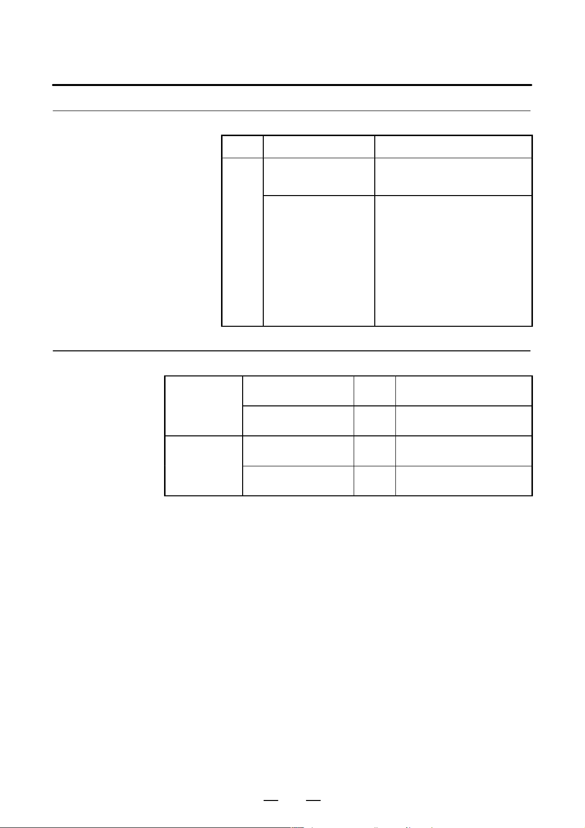
Number Message Description
Reference item
TOO MANY AXES COMMANDED
(M series)
TOO MANY AXES
COMMANDED
OPERA T OR’S MANUAL
(M series) (B–64124EN)
OPERA T OR’S MANUAL
(T series) (B–641 14EN)
OPERA T OR’S MANUAL
(M series) (B–64144EN)
The number of the commanded axes
exceeded that of simultaneously controlled axes. Correct the program.
An attempt was made to move the machine along the axes, but the number of
the axes exceeded the specified number of axes controlled simultaneously.
Alternatively, in a block where the skip
function activated by the torque–limit
reached signal (G31 P99/P98) was
specified, either moving the machine
along an axis was not specified, or
moving the machine along multiple
(T series)
axes was specified. Specify movement
only along one axis.
II.2.1 Controlled Axes
II.2.1 Controlled Axes
II.2.1 Controlled Axes
OPERA T OR’S MANUAL
(T series) (B–64134EN)
II.2.1 Controlled Axes
3
Page 22

1. AXIS CONTROL
1.2
SETTING EACH AXIS
1.2.1
Name of Axes
B–64113EN–1/01
General
Parameter
Each axis that is controlled by the CNC (including those controlled by the
PMC) must be named. Select and set names from among X, Y, Z, A, B,
C, U, V, and W (with parameter 1020).
The names of the basic axes, however, are fixed (X, Y, and Z for the M
series and X and Z for the T series). The names of additional axes can be
selected, as desired, from the names other than those for the basic axes.
The same name cannot be assigned to more than one axis.
1020 Name of the axis used for programming for each axis
[Data type] Byte axis
Set the name of the program axis for each control axis, with one of the
values listed in the following table:
Axis
name
Setting Axis
name
X 88 U 85 A 65 E 69
Y 89 V 86 B 66
Z 90 W 87 C 67
Setting Axis
name
Setting Axis
Setting
name
4
Page 23

B–64113EN–1/01
Series 0i–C
Series 0i Mate–C
1. AXIS CONTROL
NOTE
1 With the T series, when G code system A is used, neither
U, V , nor W can be used as an axis name. Only when G code
system B or C is used, U, V, and W can be used as axis
names.
2 The same axis name cannot be assigned to more then one
axis.
3 The address used by the secondary auxilliary function
(address B with the T series or, with the M series, the
address specified in parameter No.3460) cannot be used as
an axis name.
4 With the T series, when address C or A is used for
chamfering, corner R, or direct drawing dimension
programming (when the CCR parameter (bit 4 of parameter
No.3405) is set to 1), addresses C or A cannot be used as
an axis name.
5 Only with the T series, address E can be used as an axis
name. Address E cannot be used with the M series. When
address E is used as an axis name, note the following:
– When G code system A is used, address E is always
assigned to an absolute command.
– When an equal–lead threading command (G32) is
issued in the FS10/11 tape format. Use address F to
specify the thread lead.
Reference item
OPERA T OR’S MANUAL
(M series) (B–64124EN)
OPERA T OR’S MANUAL
(T series) (B–641 14EN)
OPERA T OR’S MANUAL
(M series) (B–64144EN)
OPERA T OR’S MANUAL
(T series) (B–64134EN)
II.2.2 NAMES OF AXES
II.2.2 NAMES OF AXES
II.2.2 NAMES OF AXES
II.2.2 NAMES OF AXES
5
Page 24
1. AXIS CONTROL
Metric
mm
system
machine
input
machine
inch
input
Inch
mm
system
machine
input
machine
inch
input
Metric
mm
system
machine
input
machine
inch
input
Inch
mm
system
machine
input
machine
inch
input
1.2.2
Increment System
B–64113EN–1/01
General
The increment system consists of the least input increment (for input ) and
least command increment (for output). The least input increment is the
least increment for programming the travel distance. The least command
increment is the least increment for moving the tool on the machine. Both
increments are represented in mm, inches, or degrees.
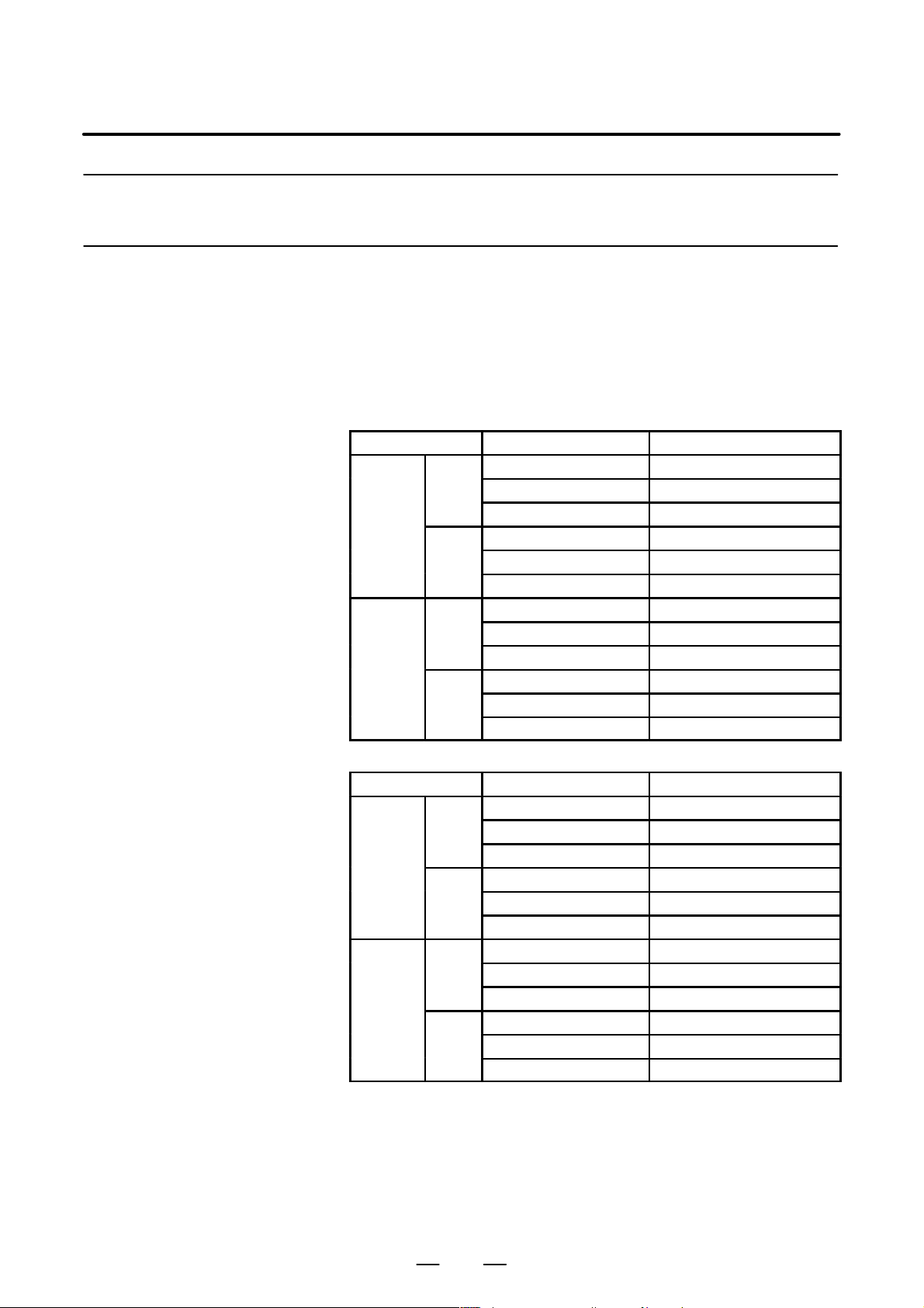
The increment system is classified as either IS–B or IS–C (Tables 1.2.2(a)
and 1.2.2 (b)). Select IS–B or IS–C using bit 1 (ISC) of parameter 1004.
Table 1.2.2 (a) Increment system IS–B
Least input increment Least command increment
0.001mm(Diameter) 0.0005mm
0.001mm(Radius) 0.001mm
0.001deg 0.001deg
0.0001inch(Diameter) 0.0005mm
0.0001inch(Radius) 0.001mm
0.001deg 0.001deg
0.001mm(Diameter) 0.00005inch
0.001mm(Radius) 0.0001inch
0.001deg 0.001deg
0.0001inch(Diameter) 0.00005inch
0.0001inch(Radius) 0.0001inch
0.001deg 0.001deg
Table 1.2.2 (b) Increment system IS–C
Least input increment Least command increment
0.0001mm(Diameter) 0.00005mm
0.0001mm(Radius) 0.0001mm
0.0001deg 0.0001deg
0.00001inch(Diameter) 0.00005mm
0.00001inch(Radius) 0.0001mm
0.0001deg 0.0001deg
0.0001mm(Diameter) 0.000005inch
0.0001mm(Radius) 0.00001inch
0.0001deg 0.0001deg
0.00001inch(Diameter) 0.000005inch
0.00001inch(Radius) 0.00001inch
0.0001deg 0.0001deg
6
Page 25
B–64113EN–1/01
Parameter
1. AXIS CONTROL
NOTE
Diameter programming is used only for T series. Diameter
programming or radius programming is determined by
parameter DIAx (No. 1006#3) for each axis. Also,
parameter IPR (No. 1004#7) can make the least input
increment of IS–B and IS–C ten times the least command
increment on each axis.
#7 #6 #5 #4 #3 #2 #1 #0
0000 INI
The following parameter can be set at “Setting screen”.
[Data type] Bit
INI Unit of input
0 : In mm
1 : In inches
#7 #6 #5 #4 #3 #2 #1 #0
1001 INM
NOTE
When this parameter is set, the power must be turned off
before operation is continued.
[Data type] Bit
INM Least command increment on the linear axis
0 : In mm (metric system machine)
1 : In inches (inch system machine)
#7 #6 #5 #4 #3 #2 #1 #0
IPR1004
IPR
ISC
ISC ISA
NOTE
After setting this parameter, turn the power of f then on again
so that the setting will take effect.
[Data type] Bit
ISA, ISC The least input increment and least command increment are set.
ISC ISA Least input increment and
least command increment
0 0 0.001mm, 0.001deg, or 0.0001inch IS-B
0 1 0.01mm, 0.01deg, or 0.001inch IS-A
1 0 0.0001mm, 0.0001deg, or 0.00001inch IS-C
7
Symbol
Page 26
1. AXIS CONTROL
Series 0i–C
Series 0i Mate–C
B–64113EN–1/01
NOTE
IS–A is not available.
IPR Whether the least input increment for each axis is set to a value 10 times as
large as the least command increment is specified, in increment systems
of IS–B and IS–C, mm input.
0 : The least input increment is not set to a value 10 times as large as the
least command increment.
1 : The least input increment is set to a value 10 times as large as the least
command increment.
If IPR is set to 1, the least input increment is set as follows:
Input increment Least input increment
IS-B 0.01 mm, 0.01 deg, or 0.0001 inch
IS-C 0.001 mm, 0.001 deg, or 0.00001 inch
NOTE
For IS–A, the least input increment cannot be set to a value
10 times as large as the least command increment.
When inch of input is specified, the least input increment
does not become 10 times as large as the least command
increment.
Reference item
#7 #6 #5 #4 #3 #2 #1 #0
1006 DIAx
NOTE
When this parameter is changed, turn off the power before
continuing operation.
[Data type] Bit axis
DIAx Either a diameter or radius is set to be used for specifying the amount of
travel on each axis.
0 : Radius
1 : Diameter
OPERA T OR’S MANUAL
(M series) (B–64124EN)
OPERA T OR’S MANUAL
(T series) (B–641 14EN)
OPERA T OR’S MANUAL
(M series) (B–64144EN)
II.2.3 Increment System
II.2.3 Increment System
II.2.3 Increment System
OPERA T OR’S MANUAL
(T series) (B–64134EN)
8
II.2.3 Increment System
Page 27

B–64113EN–1/01
1.2.3
Specifying the Rotation Axis
1. AXIS CONTROL
General
Parameter
Bit 0 (ROTx) of parameter 1006 can be used to set each axis to a linear
axis or rotation axis. Bit 1 (ROSx) of parameter 1006 can be used to select
the rotation axis type, A or B, for each axis. See the explanation of the
parameters for details of types A and B.
When the roll over function is used, the values displayed for absolute
coordinates are rounded by the shift amount per rotation, as set in
parameter No. 1260. This can prevent coordinates for the rotation axis
from overflowing. Displayed values for relative coordinates are also
rounded by the angle corresponding to one rotation when bit 2 (RRLx) of
parameter No. 1008 is set to 1. The roll–over function is enabled by
setting bit 0 (ROAx) of parameter 1008 to 1.
For an absolute command, the coordinates after the tool has moved are
values rounded by the angle corresponding to one rotation set in
parameter No. 1260. The tool moves in the direction in which the final
coordinates are closest when bit 1 of parameter No. 1008 is set to 0. For
an incremental command, the tool moves the angle specified in the
command.
#7 #6 #5 #4 #3 #2 #1 #0
1006 ROSx ROTx
NOTE
After setting this parameter, turn the power of f then on again
so that the setting will take effect.
[Data type] Bit axis
ROTx, ROSx Setting linear or rotation axis.
ROSx ROTx Meaning
0 0 Linear axis
(1) Inch/metric conversion is done.
(2) All coordinate values are linear axis type.
(Not rounded in 0 to 360°)
(3) Stored pitch error compensation is linear axis type
(Refer to parameter No. 3624)
0 1 Rotation axis (A type)
(1) Inch/metric conversion is not done.
(2) Machine coordinate values are rounded in 0 to 360_. Ab-
solute coordinate values and relative coordinate values
are rounded or not rounded by parameter No. 1008#0
and #2.
(3) Stored pitch error compensation is the rotation type. (Re-
fer to parameter No. 3624)
(4) Automatic reference position return (G28, G30) is done in
the reference position return direction and the move
amount does not exceed one rotation.
9
Page 28

1. AXIS CONTROL
B–64113EN–1/01
ROSx MeaningROTx
1 0 Setting is invalid (unused)
1 1 Rotation axis (B type)
(1) Inch/metric conversion is not done.
(2) Machine coordinate values, absolute coordinate values
and relative coordinate values are linear axis type. (Is not
rounded in 0 to 360_)
(3) Stored pitch error compensation is linear axis type (Refer
to parameter No. 3624)
(4) The rotation axis roll over function and index table index-
ing function (M series) cannot be used.
#7 #6 #5 #4 #3 #2 #1 #0
1008 RRLx RABx ROAx
NOTE
After setting this parameter, turn the power of f then on again
so that the setting will take effect.
[Data type] Bit axis
ROAx The roll–over function of a rotation axis is
0 : Invalid
1 : Valid
NOTE
ROAx specifies the function only for a rotation axis (for
which ROTx, #0 of parameter No. 1006, is set to 1)
RABx In the absolute commands, the axis rotates in the direction
0 : In which the distance to the target is shorter.
1 : Specified by the sign of command value.
NOTE
RABx is valid only when ROAx is 1.
RRLx Relative coordinates are
0 : Not rounded by the amount of the shift per one rotation
1 : Rounded by the amount of the shift per one rotation
NOTE
1 RRLx is valid only when ROAx is 1.
2 Assign the amount of the shift per one rotation in parameter
No. 1260.
10
Page 29
B–64113EN–1/01
deg
deg
Series 0i–C
1. AXIS CONTROL
1260 Amount of a shift per one rotation of a rotation axis
NOTE
1 After setting the parameter, turn off the power once and turn
it on again to operate the machine.
2 This parameter is valid only when ROAx = 1.
[Data type] Two–word axis
[Valid data range] 1000 to 9999999
Note
Reference item
[Unit of data]
Increment system Unit of data Standard value Unit
IS–A 0.01 36000
IS–B 0.001 360000
IS–C 0.0001 3600000
Set the amount of a shift per one rotation of a rotation axis.
NOTE
Rotary axis roll–over function cannot be used together with
the indexing function of the index table.
OPERA T OR’S MANUAL
(M series) (B–64124EN)
OPERA T OR’S MANUAL
(T series) (B–641 14EN)
II.20.2 Rotary Axis Roll–over
II.19.2 Rotary Axis Roll–over
Series 0i Mate–C
OPERA T OR’S MANUAL
(T series) (B–64134EN)
11
II.18.1 Rotary Axis Roll–over
Page 30

1. AXIS CONTROL
1.2.4
Controlled Axes Detach
B–64113EN–1/01
General
Signal
Controlled axis detach
signals
DTCH1 – DTCH4
<G124#0–#3>
[Classification] Input signal
[Function] These signals detach the control axes from control.
These signals release the specified control axes from control by the CNC.
When attachments are used (such as a detachable rotary table), these
signals are selected according to whether the attachments are mounted.
The signals can also be used for switching the C axis and spindle on lathes.
When multiple rotary tables are used in turn, the tables must use motors
of the same model. Absolute pulse coders cannot be used.
These signals are provided for each control axis; the affixed number of the
signal name shows the control axis number.
DTCH 1
1 ..... The 1st axis is detached.
2 ..... The 2nd axis is detached.
::
::
[Operation] When the signals are 1, the control unit operates as follows:
1) Position control is not executed at all. Servo motor excitation is cut.
2) Servo alarm on the axis is ignored.
3) Axis interlock signal is assumed to be zero on the detached axis.
4) A command for automatic or manual operation is effective for the axis,
but do not execute the command. The command is accepted but the
operation is restrained, because the axis interlock is 0. In an automatic
operation, the execution may stop and hold at the block.
5) Position display also displays the position of the detached axis.
12
Page 31

B–64113EN–1/01
Controlled axis detach
status signals
MDTCH1 – MDTCH4
<F110#0–#3>
[Classification] Output signal
[Function] These signals notify the PMC that the corresponding axes have been
[Output condition] These signals are 1 in the following case:
1. AXIS CONTROL
released from control.
These signals are provided for each control axis; the affixed number of the
signal name shows the control axis number.
MDTCH 1
1 ..... The 1st axis is detached.
2 ..... The 2nd axis is detached.
::
::
– When the corresponding axes are released from control
These signals are 0 in the following case:
– When the corresponding axes are under control
Signal address
Parameter
#7 #6 #5 #4 #3 #2 #1 #0
G124 DTCH4 DTCH3 DTCH2 DTCH1
#7 #6 #5 #4 #3 #2 #1 #0
F110 MDTCH4 MDTCH3 MDTCH2 MDTCH1
#7 #6 #5 #4 #3 #2 #1 #0
RMVx0012
Setting entry is acceptable.
[Data type] Bit axis
RMVx Releasing the assignment of the control axis for each axis
0 : Not released
1 : Released
NOTE
RMVx is valid when the bit 7 (RMBx) in parameter 1005 is 1.
#7 #6 #5 #4 #3 #2 #1 #0
RMBx1005 MCCx
[Data type] Bit axis
RMBx Releasing the assignment of the control axis for each axis (signal input
and setting input)
0 : Invalid
1 : Valid
13
Page 32

1. AXIS CONTROL
Caution
B–64113EN–1/01
MCCx When an axis is released from control, control for the MCC signal for the
corresponding servo amplifier is
0 : Disabled
1 : Enabled
NOTE
If the servo motor for an axis is connected to a 2–axis or
other multiaxis amplifier, releasing the axis from control
causes servo alarm 401 (V ready off) to be output. This
alarm can be disabled by this parameter. When the servo
motor is disconnected from the CNC, however, servo alarm
401 is output, regardless of the value of the parameter , due
to the nature of multiaxis amplifier.
CAUTION
When a 2–axis or 3–axis amplifier is used, releasing only
one axis from control results in the output of servo alarm 401
(V ready off). Use 1–axis amplifiers for those axes to be
released from control, e.g., by replacing the rotary table.
Note
NOTE
1 Controlled axis detach signals DTCH1 <G124#0>, DTCH2
<G124#1>, DTCH3 <G124#2>, … can be changed from 1
to 0 or from 0 to 1 when the power is first turned on or when
no movement is being executed along the corresponding
axis. If these signals are changed from 0 to 1 when the tool
is moving along the corresponding axis, the axis is released
from control upon completion of the movement.
2 For these signals to be attached, parameter No. 1005#7
must be set, indicating the axes are detachable.
3 Setting parameter No. 0012#7 from the MDI panel detaches
the axes in the same way as these signals.
4 Those axes that are released from control lose their
reference positions. Reference position return must,
therefore, be performed for the axes prior to executing move
commands for the axes. Specifying a move command
before reference position return has been performed
causes alarm 224 to be output (the alarm can be disabled
by setting bit 0 (ZRNx) of parameter 1005).
14
Page 33

B–64113EN–1/01
1.2.5
Outputting the Movement State of an Axis
1. AXIS CONTROL
General
Signal
Axis moving signals
MV1 – MV4
<F102#0–#3>
[Classification] Output signal
[Output condition] The signals turn to “1” in the following cases:
The movement state of each axis can be output to the PMC.
[Function] These signals indicate that a control axis is moving.
The signals are provided for each control axis, and the number in the
signal name corresponds to the control axis number.
MV 1
1 ..... The 1st axis is moving.
2 ..... The 2nd axis is moving.
3 ..... The 3rd axis is moving.
::
::
. The corresponding axis has started moving.
. In manual handle feed mode, the handle feed axis of the corresponding
axis has been selected.
The signals turn to “0” in the following case:
. When the move command for the corresponding axis has been
distributed (when bit 6 (MVX) of parameter 3003 is 0)
. When deceleration for the corresponding axis has been completed and
the axis is set to the in–position condition. If in–position check is not
performed, when the deceleration for the corresponding axis is
completed. (When bit 6 (MVX) of parameter 3003 is 1)
Setting 1 in bit 7 (MVG) of parameter 3003 prevents these signals from
being output during drawing in dynamic graphics mode (drawing without
movement of the machine) in the T series.
The axis moving signals are output in the M series.
15
Page 34

1. AXIS CONTROL
Axis moving direction
signals
MVD1 – MVD4
<F106#0–#3>
[Classification] Output signal
[Function] These signals indicate the movement direction of control axis.
[Output condition] “1” indicates the corresponding axes are moving in the minus direction,
B–64113EN–1/01
They are provided for each control axis, and the number in the signal name
corresponds to the control axis number.
MVD 1
1 ..... The moving direction of the 1st axis is minus.
2 ..... The moving direction of the 2nd axis is minus.
3 ..... The moving direction of the 3rd axis is minus.
::
::
and “0” indicates they are moving in the plus direction.
CAUTION
These signals maintain their condition during a stop,
indicating the direction of the axes’ movement before
stopping.
Signal address
F102 MV4 MV3 MV2 MV1
F106 MVD4 MVD3 MVD2 MVD1
Parameter
D Setting the output format
of the axis moving signal
[Data type] Bit
MVX The axis moving signal is set to 0 when:
MVG While drawing using the dynamic graphics function (with no machine
#7 #6 #5 #4 #3 #2 #1 #0
#7 #6
MVG3003 MVX
MVX
#5 #4 #3 #2 #1 #0
0 : Distribution for the axis is completed. (The signal is set to 0 in
deceleration.)
1 : Deceleration of the axis is terminated, and the current position is in the
in–position.
When the deceleration–time in–position check is suppressed by
setting bit 5 (NCI) of parameter No. 1601, the signal is set to 0 at the
end of deceleration.
movement), the axis moving signal is:
0: Output
1: Not output
16
Page 35

B–64113EN–1/01
Caution
1.2.6
Mirror Image
1. AXIS CONTROL
CAUTION
Axis moving signals and axis moving direction signals are
output in both automatic and manual operations.
General
Mirror image can be applied to each axis, either by signals or by
parameters (setting input is acceptable). All movement directions are
reversed during automatic operation along axes to which a mirror image
is applied.
X
A
0
When MI1 signal turned to “1” at point A
Mirror image (Example for T series)
B
B’
Z
However, the following directions are not reversed:
– Direction of manual operation and direction of movement, from the
intermediate position to the reference position during automatic
reference position return (for the M and T series)
– Approach direction for single direction positioning (G60) and shift
direction for boring cycles (G76 and G87) (for M series only)
Signal
Mirror image signal
MI1 – MI4
<G106#0–#3>
[Classification] Input signal
Mirror image check signals indicate whether mirror image is applied to
each axis. System variable #3007 contains the same information (refer
to the operator’s manual).
[Function] Apply mirror image to the specified axes.
[Operation] Apply mirror image to those axes for which the signals are 1.
These signals are provided for the controlled axes on a one–to–one basis.
A number appended to a signal represents the controlled axis number.
17
Page 36

1. AXIS CONTROL
Mirror image check
signal
MMI1 – MMI4
[Classification] Output signal
<F108#0–#3>
B–64113EN–1/01
MI 1
1 ..... Applies mirror image to the 1st axis.
2 ..... Applies mirror image to the 2nd axis.
3 ..... Applies mirror image to the 3rd axis.
::
::
The mirror image signal can be turned to “1” in the following cases:
a) During offset cancel;
b) When the CNC is in the automatic operation stop state and not in the
feed hold state.
[Function] These signals indicate the mirror image condition of each axis. The mirror
image is set by taking the logical sum of the signal from the MDI panel
and the input signal of the machine tool, then relaying the information to
the machine tool.
These signals are provided for every control axis; the numeral in the signal
name indicates the relevant control axis number.
[Output condition] These signals turn to “1” when:
Signal address
MMI 1
1 ..... Mirror image is applied to the 1st axis
2 ..... Mirror image is applied to the 2nd axis
3 ..... Mirror image is applied to the 3rd axis
::
::
· Mirror image signal MIn of the corresponding axis is “1”; or
· Mirror image of the corresponding axis is turned on by setting data
from the MDI panel.
These signals turn to “0” when:
· Mirror image signal (MIn) of the corresponding axis is “0” and the
setting of the mirror image in the control unit is turned off.
#7 #6 #5 #4 #3 #2 #1 #0
G106 MI4 MI3 MI2 MI1
#7 #6 #5 #4 #3 #2 #1 #0
F108 MMI4 MMI3 MMI2 MMI1
18
Page 37

B–64113EN–1/01
Series 0i–C
Series 0i Mate–C
Parameter
Warning
1. AXIS CONTROL
#7 #6 #5 #4 #3 #2 #1 #0
0012 MIRx
The following parameter can be set at “Setting screen.”
[Data type] Bit axis
MIRx Mirror image for each axis
0 : Mirror image is off.
1 : Mirror image is on.
WARNING
1 When programmable mirror image (M series) and ordinary
mirror image are specified at the same time, programmable
mirror image is applied first.
2 No programmable mirror image (M series) affects mirror
image check signals MMI1 to MMI4 <F108>.
Caution
Reference item
CAUTION
Even when the mirror image is applied, commands which do
not actuate mirror image (such as automatic reference
position return and manual operation) do not affect mirror
image check signals MMI1 to MMI4 <F108>.
OPERA T OR’S MANUAL
(M series) (B–64124EN)
OPERA T OR’S MANUAL
(T series) (B–641 14EN)
OPERA T OR’S MANUAL
(M series) (B–64144EN)
OPERA T OR’S MANUAL
(T series) (B–64134EN)
III.4.8 Mirror Image
III.4.8 Mirror Image
III.4.8 Mirror Image
III.4.8 Mirror Image
19
Page 38

1. AXIS CONTROL
1.2.7
Follow–up
B–64113EN–1/01
General
D When follow–up is not
performed for the axes
for which the servo is
turned off
D When follow–up is
performed for the axes
for which the servo is
turned off
When position control is disabled for the controlled axes (when the servo
is off, during emergency stop, or during a servo alarm), if the machine is
moved, a positional error occurs. Follow–up is a function for changing
the current position of the CNC and reseting the error counter to zero.
Assuming a command corresponding to the error has been specified.
You can select whether to perform follow–up for axes when the servo is
turned off.
Follow–up is always performed during emergency stop or a servo alarm.
When signal *FLWU is 1 or bit 0 (FUPx) of parameter 1819 is 1,
follow–up is not performed. The error is added to the error counter as a
servo error. In this case, the machine moves to compensate for the error
when the servo off signal changes to 0.
In general, follow–up is not used if the machine is mechanically clamped
when position control is disabled for the controlled axes.
When *FLWU is “0”, the follow-up function is engaged. The present
position of the CNC is changed to reset the error counter to zero. The
machine tool remains in a deviated position, but since the present position
of the CNC changes correspondingly, the machine moves to the correct
position when the absolute command is next applied.
In general, follow–up should be used when motors are driven by
mechanical handles.
Signal
Follow–up signal
*FLWU <G007#5>
[Classification] Input signal
Signal address
[Function] Select whether to perform follow–up when the servo is turned off for those
axes for which bit 0 (FUPx) of parameter 1819 is 0.
[Operation] 0: Performs follow–up.
1: Does not perform follow–up.
#7 #6 #5 #4 #3 #2 #1 #0
G007 *FLWU
20
Page 39

B–64113EN–1/01
Parameter
1. AXIS CONTROL
#7 #6 #5 #4 #3 #2 #1 #0
1819 FUPx
[Data type] Bit axis
FUPx To perform follow–up when the servo is off for each axis.
0 : The follow–up signal, *FLWU, determines whether follow–up is
performed or not.
When *FLWU is 0, follow–up is performed.
When *FLWU is 1, follow–up is not performed.
1 : Follow–up is not performed.
CAUTION
When the index table indexing function (M series) is used,
be sure to set FUPx of the 4th axis to 1.
Reference item
CONNECTION MANUAL
(This manual)
1.2.8 Servo Off (Mechanical handle)
21
Page 40

1. AXIS CONTROL
SVF 1
1.2.8
Servo Off (Mechanical Handle)
B–64113EN–1/01
General
Signal
Servo off signal
SVF1 – SVF4
<G126#0–#3>
Place the controlled axes in the servo off state, stop the current to the servo
motor, which disables position control. However, the position detection
feature functions continuously, so the current position is not lost.
These signals are used to prevent the servo motors from overloading when
the tools on the axes are mechanically clamped under certain machining
conditions on the machine, or to move the machine by driving the motors
by mechanical handles.
[Classification] Input signal
[Function] Select whether to place each axis in the servo off state.
These signals are provided for the controlled axes on a single axis basis.
A number appended to a signal represents a controlled axis number.
Signal address
1 ..... Servo off for the first axis
2 ..... Servo off for the second axis
3 ..... Servo off for the third axis
::
[Operation] These signals put the axes for which the signals are 1 in the servo off state
(the current to the servo motor is stopped). This disables position control.
However, the position detection feature continues to function, so the
current position is not lost.
#7 #6 #5 #4 #3 #2 #1 #0
G126 SVF4 SVF3 SVF2 SVF1
22
Page 41

B–64113EN–1/01
Caution
1. AXIS CONTROL
CAUTION
1 In general, interlock is applied to an axis while the servo off
signal for that axis is 1.
2 When one of these signals turns to “1”, the servo motor is
turned off. The mechanical clamp is done by using the
auxiliary function. Set the timing for the auxiliary function,
mechanical clamp and servo off signals as shown in the
diagram below. The clamp command auxiliary function
should be executed only after the distribution end signal
(DEN) turned to “1”.
Reference item
CONNECTION MANUAL
(This manual)
MF
Machine
clamp
SVF1, ...
FIN
Clamp command
Servo off state
1.2.7 Follow–up
Unclamp command
23
Page 42

1. AXIS CONTROL
1.2.9
Position Switch
B–64113EN–1/01
General
Signal
Position switch signal
PSW01 – PSW16
<F070#0 – F071#7>
[Classification] Output signal
[Function] Indicates that the machine coordinates along the controlled axes specified
[Output condition] These signals are 1 in the following case:
Position switch signals can be output to the PMC while the machine
coordinates along a controlled axes are within a specified ranges.
by parameters (6910 to 6925) are within the ranges specified by
parameters (6930 to 6945 and 6950 to 6965). Up to 16 position switch
signals can be output.
(Using 11 or more position switches requires setting the EPS parameter
(bit 1 of No. 6901.)
· When the machine coordinates along the controlled axes are within the
specified ranges.
Signal address
These signals are 0 in the following case:
· When the machine coordinates along the controlled axes are not within
the specified ranges.
#7 #6 #5 #4 #3 #2 #1 #0
PSW08F070 PSW07 PSW06 PSW05 PSW04 PSW03 PSW02 PSW01
PSW16F071 PSW15 PSW14 PSW13 PSW12 PSW11 PSW10 PSW09
24
Page 43

B–64113EN–1/01
Parameter
D Increasing the number of
position switch signals
1. AXIS CONTROL
#7
6901
[Data type] Bit
IGP During follow–up for the absolute position detector, position switch
EPS The number of position switches is:
PCM Position switch signals are output:
PSF In AI contour control, AI advanced preview control or advanced preview
#6 #5 #4 #3
PSF
#2
PCM#1EPS
#0
IGP
signals are:
0 : Output
1 : Not output
0 : Up to 10.
1 : Up to 16.
0 : Without considering acceleration/deceleration and servo delay.
1 : With considering acceleration/deceleration and servo delay.
control mode, position switches are:
0 : Not used.
1 : Used.
To use the position switches in any of the following modes, set this
parameter:
AI contour control, AI advanced preview control mode or advanced
preview control mode
NOTE
The position switch signals are output considering
acceleration/deceleration after interpolation and servo
delay. Acceleration/deceleration after interpolation and
servo delay are considered even for position switch signal
output in a mode other than the AI contour control, AI
advanced preview control, and advanced preview control
modes. When this parameter is set to 1, however, signals
are output from the position switches at different times from
the specified ones.
25
Page 44

1. AXIS CONTROL
D Setting the
correspondence
between the position
switch signals and the
controlled axes
B–64113EN–1/01
6910 Axis corresponding to the first position switch
6911 Axis corresponding to the second position switch
6912 Axis corresponding to the third position switch
6913 Axis corresponding to the fourth position switch
6914 Axis corresponding to the fifth position switch
6915 Axis corresponding to the sixth position switch
6916 Axis corresponding to the seventh position switch
6917 Axis corresponding to the eighth position switch
6918 Axis corresponding to the ninth position switch
6919 Axis corresponding to the tenth position switch
6920 Axis corresponding to the eleventh position switch
6921 Axis corresponding to the twelveth position switch
6922 Axis corresponding to the thirteenth position switch
6923 Axis corresponding to the fourteenth position switch
6924 Axis corresponding to the fifteenth position switch
6925 Axis corresponding to the sixteenth position switch
[Data type] Byte
[Valid data range] 0 to Number of controlled axes
These parameters sequentially specify the numbers of the controlled axes
corresponding to the 1st through 16th position switch functions. The
corresponding position switch signal is output to the PMC when the
machine coordinate of the corresponding axis is within the range set in
parameters.
NOTE
1 Set 0 for the number corresponding to a position switch
which is not to be used.
2 Parameter Nos. 6920 to 6925 are valid only when bit 1
(EPS) of parameter No. 6901 is 1.
26
Page 45

B–64113EN–1/01
D Setting the machine
coordinate ranges for
which the position
switch signals are output
D Maximum operation
range
6930 Maximum operation range of the first position switch
6931 Maximum operation range of the second position switch
6932 Maximum operation range of the third position switch
6933 Maximum operation range of the fourth position switch
6934 Maximum operation range of the fifth position switch
6935 Maximum operation range of the sixth position switch
6936 Maximum operation range of the seventh position switch
6937 Maximum operation range of the eighth position switch
6938 Maximum operation range of the ninth position switch
6939 Maximum operation range of the tenth position switch
1. AXIS CONTROL
6940 Maximum operation range of the eleventh position switch
6941 Maximum operation range of the twelveth position switch
6942 Maximum operation range of the thirteenth position switch
6943 Maximum operation range of the fourteenth position switch
6944 Maximum operation range of the fifteenth position switch
6945 Maximum operation range of the sixteenth position switch
[Data type] 2–word
[Unit of data]
Increment system IS–A IS–B IS–C Unit
Metric machine 0.01 0.001 0.0001 mm
Inch machine 0.001 0.0001 0.00001 inch
Rotation axis 0.01 0.001 0.0001 deg
[Valid data range] –99999999 to 99999999
These parameters sequentially set the maximum operation ranges of the
1st through 16th position switches.
NOTE
Parameter Nos. 6940 to 6945 are valid only when bit 1
(EPS) of parameter No. 6901 is 1.
27
Page 46

1. AXIS CONTROL
D Minimum operation
range
B–64113EN–1/01
6950 Minimum operation range of the first position switch
6951 Minimum operation range of the second position switch
6952 Minimum operation range of the third position switch
6953 Minimum operation range of the fourth position switch
6954 Minimum operation range of the fifth position switch
6955 Minimum operation range of the sixth position switch
6956 Minimum operation range of the seventh position switch
6957 Minimum operation range of the eighth position switch
6958 Minimum operation range of the ninth position switch
6959 Minimum operation range of the tenth position switch
6960 Minimum operation range of the eleventh position switch
6961 Minimum operation range of the twelveth position switch
6962 Minimum operation range of the thirteenth position switch
6963 Minimum operation range of the fourteenth position switch
6964 Minimum operation range of the fifteenth position switch
6965 Minimum operation range of the sixteenth position switch
[Data type] 2–word
[Unit of data]
Increment system IS–A IS–B IS–C Unit
Metric machine 0.01 0.001 0.0001 mm
Inch machine 0.001 0.0001 0.00001 inch
Rotation axis 0.01 0.001 0.0001 deg
[Valid data range] –99999999 to 99999999
These parameters sequentially set the minimum operation ranges of the
1st through 16th position switches.
NOTE
Parameter Nos. 6960 to 6965 are valid only when bit 1
(EPS) of parameter No. 6901 is 1.
28
Page 47

B–64113EN–1/01
1.3
ERROR COMPENSATION
1.3.1
Stored Pitch Error Compensation
1. AXIS CONTROL
General
If pitch error compensation data is specified, pitch errors of each axis can
be compensated in detection units per axis.
Pitch error compensation data is set for each compensation position at the
intervals specified for each axis. The origin of compensation is the
reference position to which the tool is returned.
Pitch error compensation data can be set with external devices such as the
Handy File (see Operator’s manual). Compensation data can also be set
directly with the MDI panel.
The following parameters must be set for pitch error compensation. Set
the pitch error compensation value for each pitch error compensation
position number set by these parameters.
In the following example, 33 is set for the pitch error compensation
number at the reference position.
Pitch error compensation value (absolute value)
Compensation number for
the compensation position
having the largest value
(No. 3622)
Compensation number for the
reference position (No. 3620)
3
2
1
333231
34 35 36 37
Reference position
Compensation number for the
compensation position having the
smallest value (No. 3621)
Compensation
position number
Compensation
value to be set
–3 +1 +1 +1 +2 –1 –3
–1
–2
Compensation magnification
parameter (No. 3623)
Compensation interval
parameter (No. 3624)
34 35 36 3731 32 33
· Pitch error compensation position at the reference position (for each
axis): Parameter 3620
· Pitch error compensation position having the smallest value (for each
axis): Parameter 3621
· Pitch error compensation position having the largest value (for each
axis): Parameter 3622
· Pitch error compensation magnification (for each axis): Parameter
3623
29
Page 48

1. AXIS CONTROL
B–64113EN–1/01
· Interval of the pitch error compensation positions (for each axis):
Parameter 3624
Procedure for displaying
and setting the pitch
error compensation data
PITCH
Continuous menu key
1 Set the following parameters:
⋅ Pitch error compensation position at the reference position (for
each axis): Parameter 3620
⋅ Pitch error compensation position having the smallest value (for
each axis): Parameter 3621
⋅ Pitch error compensation position having the largest value (for
each axis): Parameter 3622
⋅ Pitch error compensation magnification (for each axis):
Parameter 3623
⋅ Interval of the pitch error compensation positions (for each
axis): Parameter 3624
SYSTEM
2 Press function key
3 Press the continuous menu key
[PITCH].
key
.
, then press chapter selection soft
The following screen is displayed:
PIT–ERROR SETTING O0000 N00000
NO. DATA
0000 0
0001 0
0002 0
0003 0
(X)
0004 0
0005 0
0006 0
0007 0
0008 0
0009 0
> _
MEM **** *** *** 16:05:59
[ NO.SRH ][ ON:1 ][ OFF:0 ][ +INPUT ][ –INPUT ]
NO. DATA
0010 0
0011 0
0012 0
0013 0
0014 0
0015 0
0016 0
0017 0
0018 0
0019 0
NO. DATA
0020 0
0021 0
0022 0
0023 0
0024 0
0025 0
0026 0
0027 0
0028 0
0029 0
4 Move the cursor to the compensation position number to be set in
either of the following ways:
⋅ Enter the compensation position number and press the
[NO.SRH] soft key.
⋅ Move the cursor to the compensation position number using the
page keys,
and
and
PAGE
.
, and cursor keys, , , ,
PAGE
5 Enter a value with numeric keys and press the [INPUT] soft key.
30
Page 49

B–64113EN–1/01
Explanations
1. AXIS CONTROL
D Specifying the
compensation position
D Compensation position
number
D Interval of compensation
positions
To assign the compensation positions for each axis, specify the positive
direction or the negative direction relative to the compensation position
No. of the reference position. If the machine stroke exceeds the specified
range on either the positive direction or the negative direction, the pitch
error compensation does not apply beyond the range.
1024 compensation positions from No. 0 to 1023 are available on the
pitch error setting screen. Assign arbitrary positions for each axis using
parameters.
The number of the compensation position at the reference position
(parameter 3620), number of the compensation position having the
smallest value (parameter 3621), and number of the compensation
position having the largest value (parameter 3622) must be set for each
axis.
The name of each axis is displayed before the smallest compensation
position number on the pitch error setting screen.
The pitch error compensation positions are equally spaced to parameter
No. 3624. Set the space between two adjacent positions for each axis.
The minimum interval between pitch error compensation positions is
limited and obtained from the following equation:
Minimum interval of pitch error compensation positions = maximum
feedrate (rapid traverse rate)/3750
Unit:
· Minimum interval of pitch error compensation positions: mm, inches,
deg.
· Maximum feed rate: mm/min, inch/min, deg/min
Examples
D For linear axis
[Example] When the maximum rapid traverse rate is 15000 mm/min, the minimum
interval between pitch error compensation positions is 2 mm.
⋅ Machine stroke: –400 mm to +800 mm
⋅ Interval between the pitch error compensation positions: 50 mm
⋅ No. of the compensation position of the reference position: 40
If the above is specified, the No. of the farthest compensation position in
the negative direction is as follows:
No. of the compensation position of the reference position – (Machine
stroke on the negative side/Interval between the compensation
positions) + 1
= 40 – 400/50 + 1= 33
No. of the farthest compensation position in the positive direction is as
follows:
No. of the compensation position of the reference position + (Machine
stroke on the positive side/Interval between the compensation
positions)
= 40 + 800/50= 56
31
Page 50

1. AXIS CONTROL
B–64113EN–1/01
The correspondence between the machine coordinate and the
compensation position No. is as follows:
–400 –350 –100 –50
0
50 100 750 800
Machine
coordinate (mm)
Compensation
position number.
33 39 40 41 42 56
Compensation values are output at the positions indicated by .
Therefore, set the parameters as follows:
Parameter Setting value
3620 : Compensation number for the reference position
3621 : Smallest compensation position number
3622 : Largest compensation position number
3623 : Compensation magnification
3624 : Interval between pitch error compensation positions
40
33
56
1
50000
The compensation amount is output at the compensation position No.
corresponding to each section between the coordinates.
The following is an example of the compensation amounts.
No
Compensation
value
33 34 35 36 37 38 39 40 41 42 43 44 45 46 47 48 49
–2 –1 –1 +2 0 +1 0 +1 +2 +1 0 –1 –1 –2 0 +1 +2
Pitch error compensation value
(absolute value)
+4
+3
+2
–100
+1
0
100 200 300 400
–1
–2
–3
–4
33 34 35 36 37 38 39 40 41 42 43 44 45 46 47 48 49
–400
–300 –200
Reference
position
56
(mm)
1
32
Page 51

B–64113EN–1/01
1. AXIS CONTROL
D For rotary axis
⋅Amount of movement per rotation: 360°
⋅ Interval between pitch error compensation positions: 45°
⋅ No. of the compensation position of the reference position: 60
If the above is specified, the No. of the farthest compensation position in
the negative direction for the rotating axis is always equal to the
compensation position No. of the reference position.
The No. of the farthest compensation position in the positive direction is
as follows:
No. of the compensation position of the reference position + (Move
amount per rotation/Interval between the compensation positions)
= 60 + 360/45= 68
The correspondence between the machine coordinate and the
compensation position No. is as follows:
(+)
(61)
0.0
(68)
(60)
315.0
(67)
270.0
Reference position
45.0
(62)
90.0
(63)
(65)(64)
135.0
180.0
Compensation values are output at the positions indicated by .
(66)
225.0
Therefore, set the parameters as follows:
Parameter Setting value
3620 : Compensation number for the reference position 60
3621 : Smallest compensation position number 60
3622 : Largest compensation position number 68
3623 : Compensation magnification 1
3624 : Interval between pitch error compensation positions 45000
3625 : Movement value per rotation 360000
If the sum of the compensation values for positions 61 to 68 is not 0, pitch
error compensation values are accumulated for each rotation, causing
positional deviation.
The same value must be set for compensation positions 60 and 68.
33
Page 52

1. AXIS CONTROL
Parameter
3620
The following is an example of compensation amounts.
No
Compensation
value
61 62 63 64 65 66 67
Number of the pitch error compensation position for the reference position
60 61 62 63 64 65 66 67 68
+1 –2 +1 +3 –1 –1 –3 +2 +1
+4
+3
68
+2
(60)
+1
45 90 135 180225 270 315
for each axis
–1
–2
–3
–4
Pitch error compensation value
(absolute value)
Reference position
61 62 63 64 65 66 67
0
45 90 135 180 225 270 315
B–64113EN–1/01
68
(60)
61 62
0
45 90
(deg)
NOTE
After setting this parameter, turn the power of f then on again
so that the setting will take effect.
[Data type] Word axis
[Unit of data] Number
[Valid data range] 0 to 1023
Set the number of the pitch error compensation position for the reference
position for each axis.
3621
Number of the pitch error compensation position at extreme negative
NOTE
After setting this parameter, turn the power of f then on again
so that the setting will take effect.
[Data type] Word axis
position for each axis
[Unit of data] Number
[Valid data range] 0 to 1023
Set the number of the pitch error compensation position at the extreme
negative position for each axis.
34
Page 53

B–64113EN–1/01
1. AXIS CONTROL
3622
Number of the pitch error compensation position at extreme positive
position for each axis
NOTE
After setting this parameter, turn the power of f then on again
so that the setting will take effect.
[Data type] Word axis
[Unit of data] Number
[Valid data range] 0 to 1023
Set the number of the pitch error compensation position at the extreme
positive position for each axis.
NOTE
This value must be larger than the value of parameter (No.
3620).
3623 Magnification for pitch error compensation for each axis
NOTE
After setting this parameter, turn the power of f then on again
so that the setting will take effect.
[Data type] Byte axis
[Unit of data] 1
[Valid data range] 0 to 100
Set the magnification for pitch error compensation for each axis.
If the magnification is set to 1, the magnification is the same as the
detection unit.
3624 Interval between pitch error compensation positions for each axis
NOTE
After setting this parameter, turn the power of f then on again
so that the setting will take effect.
[Data type] Two–word axis
[Unit of data]
Increment system IS–A IS–B IS–C Unit
Metric machine 0.01 0.001 0.0001 mm
Inch machine 0.001 0.0001 0.00001 inch
Rotation axis 0.01 0.001 0.0001 deg
35
Page 54

1. AXIS CONTROL
[Valid data range] 0 to 99999999
B–64113EN–1/01
The pitch error compensation positions are equally spaced to parameter
No. 3624. Set the space between two adjacent positions for each axis.
The minimum interval between pitch error compensation positions is
limited and obtained from the following equation:
Minimum interval of pitch error compensation positions = maximum
feedrate (rapid traverse rate)/7500
Unit:
· Minimum interval of pitch error compensation positions: mm, inches,
deg.
· Maximum feed rate: mm/min, inch/min, deg/min
[Example] When the maximum rapid traverse rate is 15000 mm/min, the minimum
interval between pitch error compensation positions is 2 mm.
3625 T ravel distance per revolution in pitch error compensation of rotation axis type
NOTE
When this parameter has been set, the power must be
turned off before operation is continued.
[Data type] 2–word axis
[Valid data range] 0 to 99999999
If the pitch error compensation of rotation axis type is performed (bit 1
(ROSx) of parameter No. 1006 is set to 0 and bit 0 (ROTx) of parameter
No. 1006 is set to 1), set the travel distance per revolution. The travel
distance per revolution does not have to be 360 degrees, and a cycle of
pitch error compensation of rotation axis type can be set.
However, the travel distance per revolution, compensation interval, and
number of compensation points must satisfy the following condition:
(Travel distance per revolution) = (Compensation interval) x
(Number of compensation points)
The compensation at each compensation point must be set so that the total
compensation per revolution equals 0.
NOTE
If 0 is set, the travel distance per revolution becomes 360
degrees.
36
Page 55

B–64113EN–1/01
Warning
1. AXIS CONTROL
WARNING
1 Compensation value range
Compensation values can be set within the range from –7
x compensation magnification (detection unit) to +7 x
compensation magnification (detection unit). The
compensation magnification can be set for each axis within
the range from 0 to 100 in parameter 3623.
2 Pitch error compensation of the rotary axis
For the rotating axis, the interval between the pitch error
compensation positions shall be set to one per integer of the
amount of movement (normally 360°) per rotation. The sum
of all pitch error compensation amounts per rotation must be
made to 0. Also, set the same compensation value to a
position and the same position with one rotation.
3 Conditions where pitch error compensation is not
performed
Note that the pitch error is not compensated in the following
cases:
· When the machine is not returned to the reference
position after turning on the power. This excludes the
case where an absolute position detector is employed.
· If the interval between the pitch error compensation
positions is 0.
· If the compensation position Nos. on the positive or
negative direction do not fall within the range of 0 to
1023.
· If the compensation position Nos. do not conform to the
following relationship:
Negative side x Reference position < Positive side
37
Page 56

1. AXIS CONTROL
OPERA T OR’S MANUAL
Series 0i–C
OPERA T OR’S MANUAL
OPERA T OR’S MANUAL
Series 0i Mate–C
OPERA T OR’S MANUAL
Reference item
B–64113EN–1/01
(M series) (B–64124EN)
(T series) (B–641 14EN)
(M series) (B–64144EN)
III.8.6.3
III.8.6.4
III.11.5.2
III.8.6.3
III.8.6.4
III.11.5.2
III.8.6.3
III.8.6.4
III.11.5.2
III.8.6.3
Inputting pitch error compensation data
Outputting pitch error compensation data
Displaying and setting pitch error
compensation data
Inputting pitch error compensation data
Outputting pitch error compensation data
Displaying and setting pitch error
compensation data
Inputting pitch error compensation data
Outputting pitch error compensation data
Displaying and setting pitch error
compensation data
Inputting pitch error compensation data
(T series) (B–64134EN)
III.8.6.4
III.11.5.2
Outputting pitch error compensation data
Displaying and setting pitch error
compensation data
38
Page 57

B–64113EN–1/01
1.3.2
Backlash Compensation
General
1. AXIS CONTROL
D Backlash compensation
Function for compensating for lost motion on the machine. Set a
compensation value in parameter No. 1851, in detection units from 0 to
"9999 pulses for each axis.
D Backlash compensation
for each rapid traverse
and cutting feed
More precise machining can be performed by changing the backlash
compensating value depending on the feedrate, the rapid traverse or the
cutting feed.
Let the measured backlash at cutting feed be A and the measured backlash
at rapid traverse be B. The backlash compensating value is shown below
depending on the change of feedrate (cutting feed or rapid traverse) and
the change of the direction of movement.
Change of feedrate
Change of direction
of movement
Same direction
Opposite direction
Cutting feed to
cutting feed
0 "α
"A "B "(B+α)
Rapid traverse
to rapid traverse
0
Rapid traverse
to cutting feed
@ a = (A–B)/2
@ The positive or negative direction for compensating values is the
direction of movement.
Stopped during cutting feed Stopped during rapid traverse
Cutting feed to
rapid traverse
" (*α)
" (B+α)
αα
AB
⇒⇒
a : Overrun
@ Assign the measured backlash at cutting feed (A) in parameter No.
1851 and that at rapid traverse (B) in parameter No. 1852.
39
Page 58

1. AXIS CONTROL
Parameter
[Valid data range] –9999 to +9999
B–64113EN–1/01
#7 #6 #5 #4 #3 #2 #1 #0
1800 RBK
[Data type] Bit
RBK Backlash compensation applied separately for cutting feed and rapid
traverse
0 : Not performed
1 : Performed
1851 Backlash compensating value for each axis
[Data type] Word axis
[Unit of data] Detection unit
Set the backlash compensating value for each axis.
When RBK is 1, set the backlash compensating value for cutting feed.
Caution
When the machine moves in the opposite direction from to the reference
position return direction after the power is turned on, the first backlash
compensation is performed.
1852 Backlash compensating value used for rapid traverse for each axis
[Data type] Word axis
[Unit of data] Detection unit
[Valid data range] –9999 to +9999
Set the backlash compensating value used in rapid traverse for each axis.
This parameter is valid when RBK is set to 1.
CAUTION
The backlash compensation for rapid traverse and cutting
feed is not performed until the first reference position return
is completed after the power is turned on. Under this state,
the normal backlash compensation is performed according
to the value specified in parameter No. 1851 irrespective of
a rapid traverse or a cutting feed.
Note
NOTE
When backlash compensation is applied separately for
cutting feed and rapid traverse, jog feed is regarded as
cutting feed.
40
Page 59

B–64113EN–1/01
1.3.3
Bidirectional Pitch Error Compensation
1. AXIS CONTROL
Outline
Setting data
In bidirectional pitch error compensation, different pitch error
compensation amounts can be set for travel in the positive direction and
that in the negative direction, so that pitch error compensation can be
performed differently in the two directions, in contrast to stored pitch
error compensation, which does not distinguish between the directions of
travel. In addition, when the direction of travel is reversed, the
compensation amount is automatically calculated from the pitch error
compensation data to perform compensation in the same way as in
backlash compensation. This reduces the difference between the paths in
the positive and negative directions.
1. Setting parameters
Set the following parameters for each axis.
Table 1.3.3 (a)
Data number Description
3605#0 Bidirectional pitch error compensation,
1: Enabled / 0: Disabled
3620 Number of the pitch error compensation point of the refer-
ence position
3621 Number of the most distant pitch error compensation point
on the – side for travel in the positive direction
3622 Number of the most distant pitch error compensation point
on the + side for travel in the positive direction
3623 Pitch error compensation magnification
3624 Pitch error compensation point interval
3625 For a rotation axis, amount of travel per rotation in pitch
error compensation
3626 Number of the most distant pitch error compensation point
on the – side for travel in the negative direction
3627 Pitch error compensation amount (absolute value) at the
reference position when the machine moves to the refer-
ence position in the direction opposite to that of a reference
position return
2. Pitch error compensation data
The compensation point numbers can be from 0 to 1023 and from 3000
to 4023. This data may be used for both the positive and negative
directions. Note, however, that the set of compensation data for a given
axis cannot extend over 1023 and 3000.
41
Page 60

1. AXIS CONTROL
B–64113EN–1/01
Data setting example
Parameter No.3621
Set of pitch error compensation data
for the positive direction.
Parameter No.3626
Set of pitch error compensation data
for the negative direction.
The pitch error compensation data numbers in this range are
from 0 to 1023 or from 3000 to 4023.
↓
Set of n data items
↓
Set of n data items
Parameter No.3622
↓
↑
Fig. 1.3.3 (a)
If the direction of a manual reference position return is positive on an axis
(linear axis) having the pitch error amounts shown in the figure below
(Fig. 1.3.3 (b)), set the data given in the table below (Table 1.3.3 (b)).
Pitch error compensation amount
(absolute value)
+3
+2
+1
Positive–
direction error
amount
–40.0 –30.0 –20.0 –10.0 0.0 10.0 20.0 30.0 40.0
–1
–2
–3
–4
Fig. 1.3.3 (b)
T able 1.3.3 (b) Positive–direction pitch error data
Compensation
point number
Compensation
amount to be set
20 21 22 23 24 25 26 27
–1 +1 0 +1 +1 +2 –1 –1
Machine
coordinates
Negative–
direction error
amount
42
Page 61

B–64113EN–1/01
1. AXIS CONTROL
As pitch error data, always set incremental values as viewed in the
negative direction (direction toward the left in Fig. 1.3.3 (b)).
T able 1.3.3 (c) Negative–direction pitch error data
Compensation
point number
Compensation
amount to be set
30 31 32 33 34 35 36 37
–1 +1 –1 +2 –1 +2 –1 –2
Set negative–direction pitch error data for all the points for which
positive–direction pitch error data has been set.
As negative–direction pitch error data, always set incremental values as
viewed in the negative direction.
T able 1.3.3 (d)
Data
number
3605#0 1 Bidirectional pitch error compensation,
3620 23 Number of the pitch error compensation point for the
3621 20 Number of the most distant pitch error compensation
3622 27 Number of the most distant pitch error compensation
Setting Description
1: Enabled / 0: Disabled
reference position
point on the – side for travel in the positive direction
point on the + side for travel in the positive direction
3623 1 Pitch error compensation magnification
3624 10000 Pitch error compensation point interval
3625 – For a rotation axis, amount of travel per rotation in
pitch error compensation
3626 30 Number of the most distant pitch error compensation
point on the – side for travel in the negative direction
3627 –2 Pitch error compensation amount (absolute value) at
the reference position when the machine moves to
the reference position in the direction opposite to that
of the reference position return
This example assumes that the direction of a manual reference position
return is positive. For parameter No. 3627, therefore, set –2, which is the
pitch error compensation amount (absolute value) at the reference
position when the machine moves to the reference position in the negative
direction.
43
Page 62

1. AXIS CONTROL
B–64113EN–1/01
Compensation example
If, in the setting example given in the previous section, the machine
moves
0.0 to 40.0,
40.0 to –40.0, and
–40.0 to 0.0
for a manual reference position return, pitch error compensation pulses
are output as follows:
Machine
coordinate
Compensation pulse
Machine
coordinate
Compensation pulse
Machine
coordinate
Compensation pulse
0.0 5.0 15.0 25.0 35.0 40.0
– –1 –2 +1 +1 +5
35.0 25.0 15.0 5.0 –5.0 –15.0 –25.0 –35.0 –40.0
–2 –1 +2 –1 +2 –1 +1 –1 –2
–35.0 –25.0 –15.0 –5.0 0.0
+1 –1 0 –1 –
When the travel direction changes from positive to negative at the
position of 40.0, the compensation for the reverse of the travel direction
is output.
A pulse of +5 is the result of the following calculation:
+5 = – ( ( –4 ) – ( +1 ) )
Pitch error associated with the positive–
direction absolute value at the position of
40.0
Pitch error associated with the negative–direction
absolute value at the position of 40.0
When the travel direction changes from negative to positive at the
position of –40.0, the compensation for the reverse of the travel direction
is output.
A pulse of –2 is the result of the following calculation:
–2 = – ( ( –1 ) – ( –3 ) )
Pitch error associated with the negative–
direction absolute value at the position of
–40.0
Pitch error associated with the positive–direction absolute value at the position of –40.0
44
Page 63

B–64113EN–1/01
1. AXIS CONTROL
Setting and displaying
data
Parameter
3605
All the compensation data can be displayed and set on the conventional
screen for the pitch error compensation data.
And those data can be input and output by the following methods.
* Input by MDI
* Input by G10
* Input and output by input/output device interface
* Input by PMC window (function code 18)
(It is not possible to input and output by the method other than the
above methods.)
Output format : The output format is as follows:
N20000 P.... ;
N21023 P.... ;
N23000 P.... ;
N24023 P.... ;
N : Pitch error compensation point No. + 20000
P : Pitch error compensation data
#7
#6 #5 #4 #3 #2 #1 #0
BDP
[Data type] Bit axis
BDP Specifies whether to use bidirectional pitch error compensation.
0 : Do not use.
1 : Use.
NOTE
When this parameter is set, the power must be turned off
before operation is continued.
3620
Number of the pitch error compensation position for the reference position for each
[Data type] Word axis
[Unit of data] Number
[Valid data range] 0 to 1023, 3000 to 4023
Set the number of the pitch error compensation position for the reference
position for each axis
axis
NOTE
When this parameter is set, the power must be turned off
before operation is continued.
45
Page 64

1. AXIS CONTROL
B–64113EN–1/01
3621
Number of the pitch error compensation position at extremely negative position for
each axis (In case of positive–direction movement)
[Data type] Word axis
[Unit of data] Number
[Valid data range] 0 to 1023, 3000 to 4023
Set the number of the pitch error compensation position at the extremely
negative position for each axis.
NOTE
When this parameter is set, the power must be turned off
before operation is continued.
3622
Number of the pitch error compensation position at extremely positive position for
each axis (In case of positive–direction movement)
[Data type] Word axis
[Unit of data] Number
[Valid data range] 0 to 1023, 3000 to 4023
Set the number of the pitch error compensation position at the extremely
positive position for each axis.
NOTE
When this parameter is set, the power must be turned off
before operation is continued.
3623 Magnification for pitch error compensation for each axis
[Data type] Byte axis
[Unit of data] 1
[Valid data range] 0 to 100
Set the magnification for pitch error compensation for each axis.
If the magnification is set to 1, the same unit as the detection unit is used
for the compensation data. If the magnification is set to 0, the pitch error
compensation is not valid.
NOTE
When this parameter is set, the power must be turned off
before operation is continued.
46
Page 65

B–64113EN–1/01
1. AXIS CONTROL
3624 Interval between pitch error compensation positions for each axis
[Data type] 2–word axis
[Unit of data]
Increment system IS–A IS–B IS–C Unit
Metric machine 0.01 0.001 0.0001 mm
Inch machine 0.001 0.0001 0.00001 inch
Rotation axis 0.01 0.001 0.0001 deg
[Valid data range] 0 to 99999999
The pitch error compensation positions are arranged with equal spacing.
The space between two adjacent positions is set for each axis. The
minimum interval between pitch error compensation positions is limited
and obtained from the following equation:
Minimum interval between pitch error compensation positions =
Maximum feedrate (rapid traverse rate) / 7500
Units:Minimum interval between pitch error compensation positions:
mm, inch, deg
Maximum feedrate : mm/min, inch/min, deg/min
NOTE
When this parameter is set, the power must be turned off
before operation is continued.
3625 Angular displacement per rotation in rotation–axis pitch error compensation
[Data type] 2–word axis
[Unit of data]
Increment system IS–A IS–B IS–C Unit
Rotation axis 0.01 0.001 0.0001 deg
[Valid data range] 0 to 99999999
For rotation–axis pitch error compensation (with bit 0 (ROT) of
parameter No. 1006 set to 1 and bit 1 (ROS) of parameter No.1006 set to
0), set angular displacement per rotation for each axis. The angular
displacement per rotation need not always be 360 degrees. The period in
rotation–axis pitch error compensation can be set.
The angular displacement per rotation, compensation interval, and
number of compensation points must satisfy the following equation:
Angular displacement per rotation =
compensation interval number of compensation points
The sum of the compensation values per rotation must always be 0.
When this parameter is set to 0, it assumes that 360 degree is set.
NOTE
When this parameter is set, the power must be turned off
before operation is continued.
47
Page 66

1. AXIS CONTROL
B–64113EN–1/01
3626
Number of the pitch error compensation position at extremely negative position for
each axis (In case of negative–direction movement)
[Data type] Word axis
[Unit of data] Number
[Valid data range] 0 to 1023, 3000 to 4023
When using bidirectional pitch error compensation, set the number of the
pitch error compensation position at the extremely negative position for
each axis in the case of negative–direction movement.
NOTE
When this parameter is set, the power must be turned off
before operation is continued.
3627
Pitch error compensation value at the reference position when a movement is
made to the reference position in the direction opposite to the reference position
return direction
[Data type] Word axis
[Unit of data] Detection unit
[Valid data range] –32768 to 32767
By using an absolute value, set a pitch error compensation value at the
reference position when a movement is made to the reference position in
the negative direction if the reference position return direction (bit 5
(ZMI) of parameter No. 1006) is positive, or when a movement is made to
the reference position in the positive direction if the reference position
return direction is negative.
NOTE
When this parameter is set, the power must be turned off
before operation is continued.
48
Page 67

B–64113EN–1/01
1. AXIS CONTROL
Note
(1)This function is enabled after a manual reference position return or an
automatic reference position return with the same sequence as that of
a manual reference position return is performed. When an absolute
position detector is used, however, the function is enabled after the
power is turned on.
(2) When the machine moves to the reference position in the reference
position return direction, set the absolute value of the pitch error
compensation pulse to 0.
(3)When this function and backlash compensation are used at the same
time, the pulse resulting from backlash compensation is superimposed
on the compensation pulse when the travel direction is reversed.
(4)When this function is used for a rotation axis, the sum of the pitch error
compensation amounts per rotation about the rotation axis must be 0
for both the positive and negative directions.
(5) The function cannot be used with the distance coded linear scale
function.
49
Page 68

1. AXIS CONTROL
B–64113EN–1/01
1.4
SETTINGS RELATED
TO SERVO–
CONTROLLED AXES
1.4.1
Parameters Related to Servo
General
The servo interface of the Series 16 features the following:
S Digitally controlled AC servo motor
S Motor feedback with serial pulse coders
(1)Absolute pulse coder with a resolution of 1,000,000 pulses/rev
(2)Absolute pulse coder with a resolution of 65,536 pulses/rev
(3)Incremental pulse coder with a resolution of 10,000 pulses/rev
S Scale feedback with A/B/Z signal interface
Explanation of terms frequently used in CNC
Least command increment
The minimum unit of a command to be given from CNC to the
machine tool
Detection unit
The minimum unit which can detect the machine tool position
Command multiplier (CMR)
A constant to enable the weight of CNC command pulses to meet the
weight of pulses from the detector
Detection multiplier (DMR)
A constant to enable the weight of CNC command pulses to meet the
weight of pulses from the detector
CAUTION
The relations among the least command increment,
detection unit, CMR, and DMR are as specified below.
Least command increment = CMR detection unit
Detection unit =
The flexible feed gear function in the digital servo defines
constant DMR using two parameters (Nos. 2084 and 2085)
n and m (DMR = n/m).
Move amount per revolution of motor
DMR number of pulses of detector per revolution
50
Page 69

B–64113EN–1/01
Parameter
1. AXIS CONTROL
#7 #6 #5 #4 #3 #2 #1 #0
1800 CVR
[Data type] Bit
CVR When velocity control ready signal VRDY is set ON before position
control ready signal PRDY comes ON
0 : A servo alarm is generated.
1 : A servo alarm is not generated.
#7 #6 #5 #4 #3 #2 #1 #0
1815 APCx APZx OPTx
NOTE
When this parameter has been set, the power must be
turned off before operation is continued.
[Data type] Bit axis
OPTx Position detector
0 : A separate pulse coder is not used.
1 : A separate pulse coder is used.
APZx Machine position and position on absolute position detector when the
absolute position detector is used
0 : Not corresponding
1 : Corresponding
WARNING
When an absolute position detector is used, after primary
adjustment is performed or after the absolute position
detector is replaced, this parameter must be set to 0, power
must be turned off and on, then manual reference position
return must be performed. This completes the positional
correspondence between the machine position and the
position on the absolute position detector, and sets this
parameter to 1 automatically.
APCx Position detector
0 : Other than absolute position detector
1 : Absolute position detector (absolute pulse coder)
#7 #6 #5 #4 #3 #2 #1 #0
1816 DM3x DM2x DM1x
NOTE
When this parameter has been set, the power must be
turned off before operation is continued.
51
Page 70

1. AXIS CONTROL
Detection multiplier
B–64113EN–1/01
[Data type] Bit axis
DM1x to DM3x Setting of detection multiplier
Set value
DM3x DM2x DM1x
0
0
0
0
1
1
1
1
0
0
1
1
0
0
1
1
0
1
0
1
0
1
0
1
NOTE
When the flexible feed gear is used, do not use these
parameters. Set the numerator and denominator of DMR
to an appropriate values in parameters 2084 and 2085
respectively.
1820 Command multiplier for each axis (CMR)
NOTE
When this parameter has been set, the power must be
turned off before operation is continued.
1/2
1
3/2
2
5/2
3
7/2
4
[Data type] Byte axis
Set a command multiplier indicating the ratio of the least command
increment to the detection unit for each axis.
Least command increment = detection unit x command multiplier
Relationship between the increment system and the least command
increment
Increment system IS–A IS–B IS–C Unit
Metric machine 0.01 0.001 0.0001 mm
Inch machine 0.001 0.0001 0.00001 inch
Rotation axis 0.01 0.001 0.0001 deg
The value set in the parameter is obtained as follows:
(1)When command multiplier is 1/2 to 1/27
Valid data range: 102 to 127
Least command increment
Set value = + 100
1
(Command multiplier)
52
Page 71

B–64113EN–1/01
1. AXIS CONTROL
(2)When command multiplier is 1 to 48
Set value = 2 command multiplier
Valid data range: 2 to 96
NOTE
When command multiplier is 1 to 48, the set value must be
determined so that an integer can be set for command
multiplier.
1821 Reference counter size for each axis
[Data type] Two–word axis
[Valid data range] 0 to 99999999
Set the size of the reference counter.
NOTE
When this parameter has been set, the power must be
turned off before operation is continued.
1825 Servo loop gain for each axis
[Data type] Word axis
[Unit of data] 0.01 s
–1
[Valid data range] 1 to 9999
Set the loop gain for position control for each axis.
When the machine performs linear and circular interpolation (cutting), the
same value must be set for all axes. When the machine requires
positioning only, the values set for the axes may differ from one another.
As the loop gain increases, the response by position control is improved.
A too large loop gain, however, makes the servo system unstable.
The relationship between the positioning deviation (the number of pulses
counted by the error counter) and the feedrate is expressed as follows:
Positioning deviation =
Unit : Positioning deviation: mm, inches, or deg
Feedrate: mm/min, inches/min, or deg/min
Loop gain: s
1828 Positioning deviation limit for each axis in movement
–1
60
feedrate
(loop gain)
[Data type] Two–word axis
[Unit of data] Detection unit
[Valid data range] 0 to 99999999
53
Page 72

1. AXIS CONTROL
[Valid data range] 0 to 32767
B–64113EN–1/01
Set the positioning deviation limit in movement for each axis.
If the positioning deviation exceeds the positioning deviation limit during
movement, a servo alarm is generated, and operation is stopped
immediately (as in emergency stop).
Generally, set the positioning deviation for rapid traverse plus some
margin in this parameter.
1829 Positioning deviation limit for each axis in the stopped state
[Data type] Word axis
[Unit of data] Detection unit
Set the positioning deviation limit in the stopped state for each axis.
If, in the stopped state and the positioning deviation exceeds the
positioning deviation limit set for stopped state, a servo alarm is
generated, and operation is stopped immediately (as in emergency stop).
1850 Grid shift for each axis
[Data type] Two–word axis
[Unit of data] Detection unit
[Valid data range] –99999999 to +99999999
A grid shift is set for each axis.
T o shift the reference position, the grid can be shifted by the amount set in
this parameter. Up to the maximum value counted by the reference
counter can be specified as the grid shift.
NOTE
When this parameter has been set, the power must be
turned off before operation is continued.
54
Page 73

B–64113EN–1/01
1.4.2
Absolute Position Detection
1. AXIS CONTROL
General
Signal
Absolute position
detector battery voltage
low alarm signal
PBATL <F172#7>
[Classification] Output signal
[Function] Notifies that the life of the absolute position detector battery, which is
[Operation] The signal becomes 1 when:
Even when the power to the CNC is turned off, a battery–powered pulse
coder stores the current position. No reference position return is required
when the power to the CNC is restored.
used to keep the machine position even when the CNC power is off, is
about to expire.
Generally, this signal is used to turn on a lamp for calling the operator’s
attention.
· The battery voltage for the absolute position detector becomes lower
than or equal to the rating.
The battery need be replaced in the immediate future.
Absolute position
detector battery voltage
zero alarm signal
PBATZ <F172#6>
[Classification] Output signal
[Function] Notifies that the life of the absolute position detector battery, which is
[Operation] The signal becomes 1 when:
The signal becomes 0 when:
· The battery voltage for the absolute position detector is higher than or
equal to the rating.
used to keep the machine position even when the CNC power is off, has
expired.
· The battery voltage for the absolute position detector becomes 0 V.
The battery need be replaced before the CNC power is turned off.
The signal becomes 0 when:
· The battery voltage for the absolute position detector is higher than or
equal to 0 V.
55
Page 74

1. AXIS CONTROL
Signal address
Parameter
#7
PBATLF172
#7 #6 #5 #4 #3 #2 #1 #0
1815 APCx
#6
PBATZ
#5 #4 #3 #2 #1 #0
NOTE
When this parameter has been set, the power must be
turned off before operation is continued.
[Data type] Bit axis
APCx Position detector
0: Other than absolute position detector
1: Absolute position detector (absolute pulse coder)
B–64113EN–1/01
56
Page 75

B–64113EN–1/01
1.4.3
FSSB Setting
1. AXIS CONTROL
Overview
Connecting the CNC control section to servo amplifiers via a high–speed
serial bus (F ANUC Serial Servo Bus, or FSSB), which uses only one fiber
optics cable, can significantly reduce the amount of cabling in machine
tool electrical sections.
In a system using the FSSB, it is necessary to set up the following
parameters to specify its axes. (The other parameters should be specified
as usual.)
D Parameter No. 1023
D Parameter No. 1905
D Parameter Nos. 1910 to 1919
D Parameter Nos. 1936 and 1937
These parameters can be specified using the following methods:
1. Manual setting 1
Parameters are defaulted according to the setting of parameter No.
1023. There is no need to specify parameter Nos. 1905, 1910 to 1919,
1936 and 1937. No automatic setting is used. Note that some
functions are unusable.
2. Automatic setting
Axis settings are calculated automatically according to the
interrelationships between axes and amplifiers entered on the FSSB
setting screen. Parameter Nos. 1023, 1905, 1910 to 1919, 1936, and
1937 are specified automatically according to the results of the
calculation.
3. Manual setting 2
Parameter Nos. 1023, 1905, 1910 to 1919, 1936, and 1937 are
specified according to manually entered values. The user must be
totally familiar with the meaning of each parameter before entering
any values.
57
Page 76

1. AXIS CONTROL
B–64113EN–1/01
Slave
Manual setting 1
In an FSSB–based system, a fiber optics cable is used to connect the CNC
to servo amplifiers and separate detector interface units. These amplifiers
and separate detector interface units are called slaves. The two–axis
amplifier consists of two slaves, and the three–axis amplifier consists of
three slaves. The slaves are numbered 1, 2, ..., 10 (slave number)
sequentially, with that nearest to the CNC starting at number 1.
CNC
Controlled
axis
number
Program
axis name
(No. 1020)
1X
2Y
3Z
4A
Single–axis
amplifier
Two–axis
amplifier
M1
Single–axis
amplifier
M1: First separate detector interface unit
Slave
No.
1
2
3
4
5
The manual setting 1 is valid when the following parameter have the
following values:
Bit 0 of parameter No. 1902 = 1
Bit 1 of parameter No. 1902 = 0
Parameter Nos. 1910 to 1919 = all 0s
By manual setting 1, the value set for parameter No. 1023 when the power
is switched on is regarded as a slave number. Specifically, an axis for
which parameter No. 1023 is set to 1 is connected to the amplifier nearest
to the CNC, while an axis for which parameter No. 1023 is set to 2 is the
second one from the CNC.
CNC
Controlled
axis
number
Program
axis name
(No. 1020)
1X1
2Y3
3Z4
4A2
Servo axis
number
(No. 1023)
Two–axis
amplifier
Single–axis
amplifier
Single–axis
amplifier
X
A
Y
Z
By manual setting 1, some of the following functions and values cannot
be used, as described below. They should be used with automatic setting
or manual setting 2.
D No separate detector interface unit can be used; hence, no separate
position detectors can be used.
D No number can be skipped in parameter No. 1023; for example,
number 3 cannot be used for any axis unless number 2 is used.
58
Page 77

B–64113EN–1/01
1. AXIS CONTROL
D The following servo functions cannot be used:
- High–speed current loop
- High–speed interface axis
Automatic setting
Automatic setting can be used on the FSSB setting screen, if the following
parameter is set as follows:
Bit 0 of parameter No. 1902 = 0
On the FSSB setting screen, automatic setting should be enabled by
means of the following procedure:
1. On the amplifier setting screen, specify the axis number of a controlled
axis to be connected to each amplifier.
2. Press the [SETING] soft key. (If a warning message is displayed,
restart from step 1.)
3. On the axis setting screen, specify information about each axis, such
as a separate detector interface unit connector No.
4. Press the [SETING] soft key. (If a warning message is displayed,
repeat the procedure, starting from step 3.)
In this way , parameter Nos. 1023, 1905, 1910 to 1919, 1936, and 1937 are
set according to the results of automatic calculation. In addition, bit 1 of
parameter No. 1902 is set to 1 to indicate that each parameter has been set
up. Switching the power off then back on again causes axis setting to be
performed according to these parameter settings.
For details of the FSSB setting screen, see the FSSB data display and
setting procedure, described below.
59
Page 78

1. AXIS CONTROL
B–64113EN–1/01
Manual setting 2
If the following parameter is set, manual setting 2 can be used for each
parameter axis setting.
Bit 0 of parameter No. 1902 = 1
To perform manual setting 2, set parameter Nos. 1023, 1905, 1910 to
1919, 1936, and 1937. Refer to the Parameter Manual for the definition
of each parameter .
Example of axis configuration and manual setting 2
(Refer to the corresponding description for the meaning of each parameter.)
CNC
Controlled
axis
number
Program
axis name
(No. 1020)
1X
2Y
3Z
4A
Separate
detector interface unit
connector
No. 1 in the
first module
No. 2 in the
second module
No. 1 in the
second module
(Not used)
Single–axis
amplifier
Two–axis
amplifier
M1
Single–axis
amplifier
M2
Axis
X
A
Y
Z
M1/M2: First/second separate detector interface unit
No. 1902#0
FMD
1
No. 1910 1911 1912 1913 1914 1915 1916 1917 1918 1919
0 1 2 16 3 48 40 40 40 40
No. 1023 1905#0
FSL
1905#6
PM1
1905#7
PM2
1936 1937
X 1 0 1 0 0 0
Y 3 0 0 1 0 1
Z 4 1 0 1 0 0
A 2 1 0 0 0 0
60
Page 79

B–64113EN–1/01
FSSB display and setting
procedure
1. AXIS CONTROL
D Display
The FSSB setting screen displays FSSB–based amplifier and axis
information. This information can also be specified by the operator.
SYSTEM
1. Press the
2. To display [FSSB], press the
function key.
next menu page key several times.
3. Pressing the [FSSB] soft key causes the [AMPLIFIER SETTING]
screen (or the previously selected FSSB setting screen) to appear , with
the following soft keys displayed.
[ AMP ][ AXIS ][ MAINTE ][ ][ (OPRT) ]
The FSSB setting screens include: [AMPLIFIER SETTING], [AXIS
SETTING], and [AMPLIFIER MAINTENANCE]
Pressing the [AMP] soft key causes the [AMPLIFIER SETTING]
screen to appear.
Pressing the [AXIS] soft key causes the [AXIS SETTING] screen to
appear.
Pressing the [MAINTE] soft key causes the [AMPLIFIER
MAINTENANCE] screen to appear.
(1)Amplifier setting screen
The amplifier setting screen consists of two sections: the first section
displays information about the amplifiers, while the second section
displays information about the separate detector interface units.
AMPLIFIER SETTING O1000 N00001
NO. AMP SERIES UNIT CUR. AXIS NAME
1 A1–L α SVM–HV 40AL 1 X
2 A2–L α SVM 12A 2 Y
3 A2–M α SVM 40A 3 Z
5 A3–L β SVM 20A 4 A
NO. EXTRA TYPE PCB ID
4 M1 A 0000 DETECTOR(4AXES)
6 M2 B 12AB
>_
MDI **** *** *** 13:11:56
[ AMP ][ AXIS ][ MAINTE ][ ][ (OPRT) ]
The amplifier setting screen consists of the following items:
D NO. slave number. .
The numbers of up to ten slaves (up to six amplifiers and up to two
separate detector interface units) connected via the FSSB are
displayed sequentially, with the one nearest the CNC being number
1.
61
Page 80

1. AXIS CONTROL
B–64113EN–1/01
D AMP amplifier type. . . .
The amplifier type display consists of the letter A, which stands for
“amplifier”, a number that indicates the placing of the amplifier, as
counted from that nearest to the CNC, and a letter such as L (first
axis) or M (second axis) indicating the placing of the axis in the
amplifier.
D AXIS controlled axis number. . . .
The axis number of each controlled axis specified in parameters
(Nos. 1920 to 1929) is displayed. If a number specified in these
parameters falls outside the range of 1 and the maximum number
of controlled axes, 0 is displayed.
D NAME controlled axis name. . .
The axis name assigned to a parameter (No. 1020) corresponding
to a particular controlled axis number is displayed. If the controlled
axis number is 0, – is displayed.
D The following items are displayed as amplifier information:
S UNIT servo amplifier unit type. . . . .
S SERIES servo amplifier series. . .
S CUR. maximum rating current. . . . .
D The following items are displayed as separate detector interface
unit information:
S EXTRA
This consists of the letter M, which stands for “separate detector
interface unit”, and a number indicating the placing of the
separate detector interface unit, as counted from that nearest to
the CNC.
S TYPE
This is a letter indicating the type of the separate detector
interface unit.
S PCB ID
This consists of four digits indicating the separate detector
interface unit ID (hexadecimal). The separate detector interface
unit ID is followed by DETECTOR (8AXES) when 8–axes
separate detector interface unit or DETECTOR (4AXES) when
4–axes separate detector interface unit.
62
Page 81

B–64113EN–1/01
1. AXIS CONTROL
(2)Axis setting screen
The axis setting screen displays the information shown below:
AXIS SETTING O1000 N00001
AXIS NAME AMP M1 M2 1–DSP CS TNDM
1 X A1–L 0 0 001
2 Y A2–L 1 0 1 0 0
3 Z A2–M 0 0 0 1 0
4 A A3–L 0 0 0 0 2
>_
MDI **** *** *** 13:11:56
[ AMP ][ AXIS ][ MAINTE ][ ][ (OPRT) ]
The axis setting screen displays the following items:
D AXIS controlled axis number. . . .
This item is the placing of the NC controlled axis.
D NAME controlled axis name. . .
D AMP type of the amplifier connected to each axis. . . .
D M1 connector number for separate detector interface unit. . . . . .
1
This item is the number of the connector for separate detector
interface unit 1, specified in parameter No. 1931.
D M2 connector number for separate detector interface unit. . . . . .
2
This item is the number of the connector for separate detector
interface unit 2, specified in parameter No. 1932.
D 1–DSP
This item is the value specified in bit 0 (parameter 1DSP) of
parameter No. 1904. It is 1 for an axis (such as a learning control
axis, high–speed current loop axis, or high–speed interface axis)
that exclusively uses a DSP, which is usually shared by two axes.
D CS Cs contour controlled axis. . . . .
This item is the value specified in parameter No. 1933. It is 1 for
the Cs contour controlled axis.
D TNDM
This item is the number specified in parameter No. 1934.
Consecutive odd and even numbers are displayed for the master
and slave axes for tandem control. This item is not used in Series
0i Mate.
63
Page 82

1. AXIS CONTROL
B–64113EN–1/01
(3)Amplifier maintenance screen
The amplifier maintenance screen displays maintenance information
for servo amplifiers. This screen consists of the following two pages,
PAGE
either of which can be selected by pressing the
AMPLIFIER MAINTENANCE O1000 N00001
AXIS NAME AMP SERIES UNIT AXES CUR.
1 X A1–L α SVM–HV 2 40AL
2 Y A1–M α SVM 2 12A
3 Z A2–L β SVM 1 40A
4 A A3–L α SVM 2 20A
5 B A3–M α SVM 2 40A
6 C A4–L α SVU 1 240A
>_
MDI **** *** *** 13:11:56
[ AMP ][ AXIS ][ MAINTE ][ ][ ]
PAGE
or
key.
AMPLIFIER MAINTENANCE O1000 N00001
AXIS NAME EDITION TEST MEINTE–NO.
1 X 01A 010123 01
2 Y 01A 010123 01
3 Z 01A 010123 01
4 A 02B 010123 01
5 B 02B 010123 01
6 C 02B 010123 01
>_
MDI **** *** *** 13:11:56
[ AMP ][ AXIS ][ MAINTE ][ ][ ]
The amplifier maintenance screen displays the following items:
D AXIS controlled axis number. . . . . . . . .
D NAME controlled axis name. . . . . . . .
D AMP type of amplifier connected to each axis. . . . . . . . .
D SERIES servo amplifier series of an amplifier. . . . . . .
connected to each axis
D UNIT unit type of a servo amplifier connected to each. . . . . . . . .
axis
D AXES maximum number of axes controlled by an. . . . . . . . .
amplifier connected to each axis
D CUR. maximum rating current for amplifiers. . . . . . . . .
connected to each axis
D EDITION unit version number of an amplifier connected. . . . . .
to each axis
64
Page 83

B–64113EN–1/01
1. AXIS CONTROL
D TEST date of test performed on an amplifier. . . . . . . . .
connected to each axis
Example) 010123 = January 23, 2001
D MEINTE–No. engineering change number for an amplifier. .
connected to each axis
D Setting
On an FSSB setting screen (other than the amplifier maintenance screen),
pressing the [(OPRT)] soft key displays the following soft keys:
[ SETING ][ ][ CANCEL ][ ][ INPUT ]
T o enter data, place the machine in MDI mode or the emergency stop state,
position the cursor to the point where a desired item is to be input, then
enter the desired data and press the [INPUT] soft key (or the
INPUT key on
the MDI panel).
When the [SETING] key is pressed after data has been entered, a warning
message is displayed if the entered data contains an error. When the data
is valid, the corresponding parameter is set up.
To restore the previous value of a parameter if, for example, an entered
value is incorrect, press the [CANCEL] soft key.
When the power is switched on, values are read from the parameters and
displayed on the screen.
CAUTION
1 For the parameters to be specified on the FSSB setting
screen, do not attempt to enter values on the parameter
screen using the MDI or a G10 command. Use only the
FSSB screen to enter values for these parameters.
2 If pressing the [SETING] key results in a warning message
being displayed, retry data entry, or press the [CANCEL] key
to clear the warning message. Note that pressing the reset
key does not clear the warning message.
(1)Amplifier setting screen
AMPLIFIER SETING O1000 N00001
NO. AMP SERIES UNIT CUR. AXIS NAME
1 A1–L α SVM–HV 40AL 1 X
2 A2–L α SVM 12A 2 Y
3 A2–M α SVM 40A 3 Z
5 A3–L β SVM 20A 4 A
NO. EXTRA TYPE PCB ID
4 M1 A 0000 DETECTOR(4AXES)
6 M2 B 12AB
>_
MDI **** *** *** 13:11:56
[ AMP ][ AXIS ][ MAINTE ][ ][ (OPRT) ]
65
Page 84

1. AXIS CONTROL
B–64113EN–1/01
The amplifier setting screen displays the following items:
D AXIS controlled axis number. . .
For this item, enter a value of between 1 and the maximum number
of controlled axes. If a number that falls outside this range is
entered, the warning message FORMAT ERROR appears. If the
entered controlled axis number is duplicate or 0, the warning
message DA TA IS OUT OF RANGE appears when the [SETING]
soft key is pressed to assert the entered value. In this case, no value
can be entered for the parameter.
(2)Axis setting screen
AXIS SETTING O1000 N00001
AXIS NAME AMP M1 M2 1–DSP CS TNDM
1 X A1–L 0 0001
2 Y A2–L 1 0 1 0 0
3 Z A2–M 0 0 0 1 0
4 A A3–L 0 0 0 0 2
>_
MDI **** *** *** 13:11:56
[ SETING ][ ][ CANCEL ][ ][ INPUT ]
On the axis setting screen, the following items can be specified:
D M1 connector number for separate detector interface unit 1. . .
For an axis that uses separate detector interface unit 1, enter a
connector number using a number in the range of between 1 and the
maximum number of axes for separate detector interface unit 1.
When separate detector interface unit 1 need not be used, enter 0.
If a number that falls outside the valid range is entered, the message
FORMAT ERROR is displayed.
D M2 connector number for separate detector interface unit 2. . .
For an axis that uses separate detector interface unit 2, enter a
connector number using a number in the range of between 1 and the
maximum number of axes for separate detector interface unit 2.
When separate detector interface unit 2 need not be used, enter 0.
If a number that falls outside the valid range is entered, the message
FORMAT ERROR is displayed.
D 1–DSP
Enter 1 for the following axes, each of which exclusively uses a
DSP, which is usually shared by two axes. If a number other than
0 or 1 is entered, the message FORMAT ERROR is displayed.
S High–speed current loop axis
S High–speed interface axis
D CS Cs contour controlled axis. .
Enter 1 for the Cs contour controlled axis. If a number other than
0 or 1 is entered, the message FORMAT ERROR is displayed.
66
Page 85

B–64113EN–1/01
1. AXIS CONTROL
D TNDM
Enter odd and even numbers for the master and slave axes for
tandem control. These numbers must be consecutive and in the
range of between 1 and 4. If a number that falls outside the valid
range is entered, the message FORMAT ERROR is displayed.
This item is not used in Series 0i Mate.
When the [SETING] soft key is pressed on the axis setting screen after
data entry , the message DA T A IS OUT OF RANGE is displayed if any
of the following conditions is satisfied.
D Both M1 and M2 are nonzero for an axis.
D Any two of the 1–DSP, CS, and TNDM are nonzero for an axis.
D A duplicate value is specified for M1.
D A duplicate value is specified for M2.
D A duplicate value is specified for CS.
D A duplicate value is specified for TNDM.
D An invalid master/slave axis pair is specified for TNDM.
Parameter
#7
1902
#6 #5 #4 #3 #2 #1
[Data type] Bit
FMD Specifies the FSSB setting mode.
0 : Automatic setting mode.
(If the interrelationships between axes and amplifiers are specified on
the FSSB setting screen, parameter Nos. 1023, 1905, 1910 to 1919,
1936, and 1937 are set automatically.)
1 : Manual setting 2 mode.
(Parameter Nos. 1023, 1905, 1910 to 1919, 1936, and 1937 must be
set manually.)
ASE Indicates whether automatic setting is complete, if bit 0 of parameter No.
1902 is 0 (automatic setting mode).
0 : Incomplete.
1 : Complete.
(This bit automatically becomes 1 upon the completion of automatic
setting.)
#7
1904
#6 #5 #4 #3 #2 #1 #0
ASE
#0
FMD
DSP
[Data type] Bit axis
DSP 0 : Two axes share a DSP. (Ordinary axis)
1 : One axis occupies a DSP. (Learning control axis, and so on)
Usually, the user should not attempt to manipulate this bit, because it is
set using the FSSB setting screen. It need not be used in FSSB manual
setting 2 mode.
67
Page 86

1. AXIS CONTROL
B–64113EN–1/01
#7
PM21905
#6
PM1
#5 #4 #3 #2 #1 #0
FSL
[Data type] Bit axis
FSL Specifies whether to use a fast or slow interface between a servo amplifier
and the servo software.
0 : Fast type
1 : Slow type
There are two types of servo data transfer interfaces: fast and slow types.
They are selected as described below.
D Both types are usable for single–axis amplifiers.
D For two–axis amplifiers, do not use fast type interfaces for both axes
simultaneously. Slow types can be used simultaneously for both axes.
D For three–axis amplifiers, the same rules as those for two–axis
amplifiers apply for the first and second axes, while the same rules as
those for single–axis amplifiers apply for the third axis.
D For those axes for which an odd number is set for parameter No. 1023,
the fast type must be used, except for the high–speed current loop and
high–speed interface axes, for which the slow type can also be used.
D For those axes for which an even number is set for parameter No.
1023, only the slow type is usable; this bit must be set to 1.
CNC
Controlled
axis
number
Program
axis name
(No. 1020)
1X1F
2Y3F
3Z4S
4A2S
Servo axis
number
(No. 1023)
Interface
type
(fast/slow)
Two–axis
amplifier
Single–axis
amplifier
One–axis
amplifier
X (Fast)
A (Slow)
Y (Fast)
Z (Slow)
PM1 Specifies whether the first separate detector unit is to be used.
0 : Not used.
1 : Used.
PM2 Specifies whether the second separate detector unit is to be used.
0 : Not used.
1 : Used.
If automatic setting is set as the FSSB setting mode (bit 0 of parameter
No. 1902 = 0), this parameter is set automatically when data is entered
using the FSSB setting screen. For manual setting 2 (bit 0 of parameter
No. 1902 = 1), the user must set this parameter. When using a separate
detector interface unit, a connection number must be specified separately
(parameter Nos. 1936 and 1937).
68
Page 87

B–64113EN–1/01
1910 Address conversion table value for slave 1 (ATR)
1911 Address conversion table value for slave 2 (ATR)
1912 Address conversion table value for slave 3 (ATR)
1913 Address conversion table value for slave 4 (ATR)
1914 Address conversion table value for slave 5 (ATR)
1915 Address conversion table value for slave 6 (ATR)
1916 Address conversion table value for slave 7 (ATR)
1917 Address conversion table value for slave 8 (ATR)
1918 Address conversion table value for slave 9 (ATR)
1919 Address conversion table value for slave 10 (ATR)
[Data type] Byte
[Valid data range] 0 to 7, 16, 40, and 48
An address conversion table value must be specified for each of slaves 1
to 10. The term “slave” refers to any of the servo amplifiers and separate
detector interface units connected to the CNC. Each slave is assigned a
number of between 1 and 10 sequentially, with the one nearest to the CNC
assigned number 1. A two–axis amplifier is regarded as being two slaves,
while a three–axis amplifier is regarded as being three slaves. Each of
these parameters is set depending on whether the slave is an amplifier or
separate detector interface unit, as follows:
f When the slave is an amplifier:
The parameter is set to the “value in parameter No. 1023 for an axis
to which the amplifier is assigned,” minus 1.
f When the slave is a separate detector interface unit:
The parameter is set to 16
for the first separate detector interface unit
(that nearest to the CNC) or to 48
interface unit (that farthest from the CNC).
f When there is no slave:
The parameter is set to 40
.
If automatic setting is set as the FSSB setting mode (bit 0 of parameter
No. 1902 = 0), this parameter is set automatically when data is entered on
the FSSB setting screen. For manual setting 2 (bit 0 of parameter No.
1902 = 1), the parameter must be set manually.
1. AXIS CONTROL
for the second separate detector
69
Page 88

1. AXIS CONTROL
f Example of axis configuration and parameter setting
CNC
Controlled
axis
number
Program
axis name
(No. 1020)
Servo axis
number
(No. 1023)
1X1
2Y3
3Z4
4A2
Single–axis
amplifier
Two–axis
amplifier
M1
Single–axis
amplifier
M2
Slave
number
ATR
No.1910
to 1919
10
21
32
416
53
648
740
B–64113EN–1/01
Axis
X
A
Y
(M1)
2
(M2)
(None)
CNC
Controlled
axis
number
Program
axis name
(No. 1020)
Servo axis
number
(No. 1023)
1X1
2Y3
3Z4
4A2
Single–axis
amplifier
Two–axis
amplifier
M1
Single–axis
amplifier
M2
840
940
10 40
Slave
number
ATR
No.1910
to 1919
10
22
33
416
51
648
740
840
(None)
(None)
(None)
Axis
X
Y
Z
(M1)
A
(M2)
(None)
(None)
940
10 40
M1/M2: First/second separate detector interface unit
(None)
(None)
70
Page 89

B–64113EN–1/01
1. AXIS CONTROL
1920 Controlled axis number for slave 1 (FSSB setting screen only)
1921 Controlled axis number for slave 2 (FSSB setting screen only)
1922 Controlled axis number for slave 3 (FSSB setting screen only)
1923 Controlled axis number for slave 4 (FSSB setting screen only)
1924 Controlled axis number for slave 5 (FSSB setting screen only)
1925 Controlled axis number for slave 6 (FSSB setting screen only)
1926 Controlled axis number for slave 7 (FSSB setting screen only)
1927 Controlled axis number for slave 8 (FSSB setting screen only)
1928 Controlled axis number for slave 9 (FSSB setting screen only)
1929 Controlled axis number for slave 10 (FSSB setting screen only)
[Data type] Byte
[Valid data range] 0 to 8
Each of these parameters is set using a controlled axis number for a slave
numbered 1 to 10. This parameter is set automatically when data is
entered using the FSSB setting screen; do not specify it manually. For
manual setting 2, the parameter need not be set.
1931
1932
Connector number for first separate detector interface unit
(FSSB setting screen only)
Connector number for second separate detector interface unit
(FSSB setting screen only)
[Data type] Byte axis
[Valid data range] 0 to the number of connectors in each separate detector interface unit
T o use a separate detector interface unit, the user must specify a connector
number for the separate detector interface unit on each axis. This
parameter is set automatically when data is entered using the FSSB setting
screen; do not specify it manually. For manual setting 2, the parameter
need not be set.
1933 Cs contour controlled axis (FSSB setting screen only)
[Data type] Byte axis
[Valid data range] 0 and 1
To use Cs contour control, this parameter must be set to 1 for the
corresponding axis. This parameter is set automatically when data is
entered using the FSSB setting screen; do not specify it manually. For
manual setting 2, the parameter need not be set.
71
Page 90

1. AXIS CONTROL
[Valid data range] 0 to 8
[Valid data range] 0 to 7
B–64113EN–1/01
1934 Master/slave number for tandem–controlled axes (FSSB setting screen only)
[Data type] Byte axis
T o use tandem control, this parameter must be set to an odd number (for
the master axis) or to an even number (slave axis). This parameter is set
automatically when data is entered using the FSSB setting screen; do not
set it manually. For manual setting 2, the parameter need not be set.
1936 Connector number for first separate detector interface unit
1937 Connector number for second separate detector interface unit
[Data type] Byte axis
To use a separate detector interface unit, this parameter must be set to
“connection number for the separate detector interface unit,” minus 1; that
is, 0 for connector number 1, 1 for connector number 2, and so on. It is
also necessary to set up bits 6 and 7 of parameter No. 1905. For an axis
that does not use a separate detector interface unit, 0 is specified for the
parameter. Any connector can be used for any axis, however the
connectors in a single separate detector interface unit should be used in
ascending order of connector number. For instance, connector 4 of a
separate detector interface unit cannot be used without using connector
3 of the same separate detector interface unit.
Example)
Connector
Controlled
axis
X 1 Not used 0 0 0,1
Y Not used 2 0 1 1,0
Z Not used 1 0 0 1,0
A Not used Not used 0 0 0,0
number for
first sepa-
rate detector
interface
unit
Connector
number for
second sep-
arate detec-
tor interface
unit
No.1936 No.1937
No.1905
(#7, #6)
If the FSSB setting mode is automatic setting (bit 0 of parameter No. 1902
= 0), this parameter is set automatically when data is entered using the
FSSB setting screen. For manual setting 2 (bit 0 of parameter No. 1902
= 1), the user must set this parameter.
72
Page 91

B–64113EN–1/01
Alarm and message
D Servo alarms
1. AXIS CONTROL
Number Message Description
456 ILLEGAL CURRENT
LOOP
457 ILLEGAL HI HRV (250US) Use of high–speed HRV is specified al-
458 CURRENT LOOP
ERROR
459 HI HRV SETTING
ERROR
The current control cycle settings (parameter No. 2004, bit 0 of parameter
No. 2003, and bit 0 of parameter No.
2013) are incorrect. Possible problems
are as follows.
– For the two axes whose servo axis
numbers (settings of parameter No.
1023) are an odd number followed
by an even number (a pair of axes
1 and 2, for example), a different
current control cycle is set for each
of the axes.
– The requirements for slaves need-
ed for the set current control cycle,
including the number, type, and
connection method of them, are not
satisfied.
though the current control cycle is 200
µs.
The current control cycle setting does
not match the actual current control
cycle.
For the two axes whose servo axis numbers (settings of parameter No. 1023) are
an odd number followed by an even
number (a pair of axes 1 and 2, for example), the SVM for one of the axes sup ports high–speed HRV control but the
SVM for the other does not. Refer to the
SVM specification.
460 n AXIS : FSSB DISCON-
NECT
461 n AXIS : ILLEGAL AMP
INTERFACE
462 n AXIS : SEND CNC
DA TA FAILED
463 n AXIS : SEND SLA VE
DA TA FAILED
465 n AXIS : READ ID DATA
FAILED
73
FSSB communication was interrupted.
The most likely causes are:
1. The FSSB communication cable is
disconnected or has a broken conductor.
2. The amplifier power supply was
turned off.
3. A low–voltage alarm condition occurred in the amplifier.
The fast type interface was assigned to
both axes of a two–axis amplifier.
The slave could not receive data correctly because of an FSSB communication error.
The servo section failed to receive data
correctly because of an FSSB communication error.
An attempt to read the initial ID information for the amplifier failed when the
power was switched on.
Page 92

1. AXIS CONTROL
B–64113EN–1/01
Number DescriptionMessage
D P/S alarms
466 n AXIS : MOTOR/AMP
COMBINATION
467 n AXIS : ILLEGAL SET-
TING OF AXIS
468 HI HRV SETTING
ERROR(AMP)
Number Message Description
5134 FSSB : OPEN READY
TIME OUT
5135 FSSB : ERROR MODE The FSSB entered an error mode.
5136 FSSB : NUMBER OF
AMPS IS SMALL
The maximum current rating for the amplifier does not match that for the motor.
The servo function for the following has
not been enabled when an axis occupying a single DSP is specified on the
axis setting screen.
1. High–speed current loop
(bit 0 of parameter No. 2004 = 1)
2. High–speed interface axis
(bit 4 of parameter No. 2005 = 1)
Use of high–speed HRV is specified for
a controlled axis of an amplifier which
does not support high–speed HRV.
The FSSB did not become ready to
open during initialization.
The number of amplifiers recognized
by the FSSB is insufficient, compared
with the number of controlled axes.
5137 FSSB : CONFIGURATION
ERROR
5138 FSSB : AXIS SETTING
NOT COMPLETE
5139 FSSB : ERROR The initialization of the servo was not
5197 FSSB : OPEN TIME OUT The FSSB did not open when the CNC
The FSSB detected a configuration error. The address conversion table value (A TR) setting (parameter Nos. 1910
to 1919 and 1970 to 1979) for a slave
axis does not match the type of a slave
axis actually connected to the FSSB.
Axis setting has not been performed in
automatic setting mode. Perform axis
setting using the FSSB setting screen.
completed normally. Probable cases
are a defect of optical cable or a mistake of the connection between the amplifier and other modules.
had allowed the FSSB to open.
74
Page 93

B–64113EN–1/01
1. AXIS CONTROL
Number DescriptionMessage
1.4.4
Tentative Absolute Coordinate Setting
5198 FSSB : ID DAT A NOT
READ
5311 FSSB: ILLEGAL CON-
NECTION
The initial ID information for the amplifier cannot be read because of a failure
in the temporary assignment.
A connection related to FSSB is illegal.
This alarm is issued when either of the
following is found:
1 Two axes having adjacent servo
axis numbers (parameter No. 1023),
odd number and even number, are
assigned to amplifiers to which different FSSB systems are connected.
2 The system does not satisfy the re-
quirements for performing HRV control, and use of two pulse modules
connected to different FSSB systems having different FSSB current
control cycles is specified.
General
CNC
Absolute position detection at
power–on time
In a full–closed system with a built–in absolute position detector (serial
pulse coder) and incremental linear scale, a coordinate system is set up,
using absolute position data received from the built–in absolute position
detector when the power is switched on. After this, position control is
carried out using the linear scale incremental data. Because the machine
position obtained immediately after the power is switched on is tentative,
obtaining the accurate machine position requires making a manual
reference position return.
Even before a reference position return is made, using this function
enables a stroke limit, although the machine position obtained when the
power is switched on is approximate.
Note that this function is not intended to use an incremental linear scale
as an absolute position detector.
This function is an option.
Serial pulse coder
(absolute position detector)
Linear scale (incremental)
Ordinary position control
Fig. 1.4.4 System using tentative absolute coordinate system setting
75
Page 94

1. AXIS CONTROL
Parameter
#7
1801
[Data type] Bit
INA Specifies whether to perform absolute position communication for
B–64113EN–1/01
#6 #5 #4 #3
INA
#2 #1 #0
re–setting up the machine position at a reset after a servo alarm other than
alarm 413 (LSI overflow), 416, 445, 446, or 447 (broken–wire alarm)
occurs in a system that uses an absolute position detector, as follows:
0 : To perform.
1 : Not to perform.
NOTE
1 If INA = 0 in a system that uses tentative absolute
coordinate system setting, the machine position is
approximate after a servo alarm other than 413, 416, 445,
446, or 447 is reset, because it has been re–set up using
data received from the built–in absolute position coder.
2 When a reset is performed after a servo alarm 413, 416,
445, 446, or 447 occurs, absolute position communication
for re–setting up the machine position always takes place.
#7
1815
#6 #5
APCx
#4 #3 #2 #1
OPTx
[Data type] Bit axis
OPTx Specifies whether to use a separate position detector, as follows:
0 : Not to use.
1 : To use.
APCx Specifies whether to use a absolute position detector, as follows:
0 : Not to use.
1 : To use.
NOTE
1 When using tentative absolute coordinate system setting,
set both OPTx and APCx to 1.
2 After setting any of these parameters, turn the power off
then on again so that the setting will take effect.
#0
76
Page 95

B–64113EN–1/01
1874 Flexible feed gear numerator for built–in position detector
1875 Flexible feed gear denominator for built–in position detector
[Data type] Word axis
[Valid data range] 1 to 32,767
Specifies a flexible feed gear for a built–in position detector for each axis
when using tentative coordinate system setting, according to the
following expression:
Number of position feedback pulses per
NO.1874
=
motor revolution
NO.1875 1,000,000
NOTE
1 These parameters can be used also in a system that uses
the Inductosyn.
2 After setting any of these parameters, turn the power off
then on again so that the setting will take effect.
1. AXIS CONTROL
#7
XIAx2011
#6 #5 #4 #3 #2 #1 #0
[Data type] Bit axis
INI Specifies whether to enable tentative absolute coordinate system setting,
as follows:
0 : To disable.
1 : To enable.
NOTE
Using tentative absolute coordinate system setting requires
setting bit 1 (OPTx) of parameter No. 1815, bit 5 (APCx) of
parameter No. 1815, parameter No. 1874, and parameter
No. 1875.
77
Page 96

1. AXIS CONTROL
1.5
SETTINGS RELATED WITH COORDINA TE SYSTEMS
1.5.1
Machine Coordinate System
B–64113EN–1/01
General
High–speed G53
function
Machine coordinate system is a coordinate system set with a zero point
proper to the machine system.
A coordinate system in which the reference position becomes the
parameter-preset (No. 1240) coordinate value when manual reference
position return is performed, is set. With G53 command, the machine
coordinate system is selected and the axis can be moved at rapid traverse
to the position expressed by the machine coordinates.
This function enables the inter–rapid traverse block overlap function
between machine coordinate system select command (G53) and
positioning (rapid traverse) command (G00) blocks and allows the next
rapid traverse command (G00) to be executed at the end of the machine
coordinate system select command (G53) without decelerating to a stop.
This way, high–speed positioning becomes possible even when the
machine coordinate system select command (G53) is used.
Specifying P1 in the G53 bock enables the high–speed G53 function.
G53 IP_ P1;
G53: Machine coordinate system select command G code
(00 group)
IP_: End–point dimension word
P1: Enable high–speed G53 function
Parameter
1240
Coordinate value of the reference position on each axis in the machine
NOTE
After setting this parameter, turn the power of f then on again
so that the setting will take effect.
[Data type] Two–word axis
[Unit of data]
Increment system IS–A IS–B IS–C Unit
Metric machine 0.01 0.001 0.0001 mm
Inch machine 0.001 0.0001 0.00001 inch
Rotation axis 0.01 0.001 0.0001 deg
coordinate system
78
Page 97

B–64113EN–1/01
Series 0i–C
Series 0i Mate–C
1. AXIS CONTROL
[Valid data range] –99999999 to 99999999
Set the coordinate values of the reference positions in the machine
coordinate system.
1722 Rapid traverse deceleration rate at inter–rapid traverse block overlap
[Data type] Byte axis
[Unit of data] %
[Valid data range] 0 to 100
If a high–speed G53 command (G53 P1) block is followed by a rapid
traverse block, the latter block (rapid traverse) is executed after the
feedrate specified for each axis in the G53 P1 block has decreased to the
deceleration rate specified in this parameter.
NOTE
1 Enabling the high–speed G53 function does not require
setting the RTO parameter (bit 4 of parameter No. 1601) for
enabling inter–rapid traverse block overlap to 1.
2 If the RTO parameter (bit 4 of parameter No. 1601) is set to
1, a value specified in parameter No. 1722 is used also for
ordinary inter–rapid traverse block overlap.
Warning
Reference item
WARNING
Since the machine coordinate system must be set before
the G53 command is specified, at least one manual
reference position return or automatic reference position
return by the G28 command must be performed after the
power is turned on. This is not necessary when an
absolute–position detector is attached.
OPERA T OR’S MANUAL
(M series) (B–64124EN)
OPERA T OR’S MANUAL
(T series) (B–641 14EN)
OPERA T OR’S MANUAL
(M series) (B–64144EN)
OPERA T OR’S MANUAL
(T series) (B–64134EN)
II.7.1
II.7.1
II.7.1
II.7.1
MACHINE COORDINA TE
SYSTEM
MACHINE COORDINA TE
SYSTEM
MACHINE COORDINA TE
SYSTEM
MACHINE COORDINA TE
SYSTEM
79
Page 98

1. AXIS CONTROL
1.5.2
Workpiece Coordinate System/Addition of Workpiece Coordinate System Pair
B–64113EN–1/01
General
Setting a workpiece
coordinate system
A coordinate system used for machining a workpiece is referred to as a
workpiece coordinate system. A workpiece coordinate system is to be set
with the CNC beforehand (setting a workpiece coordinate system).
A machining program sets a workpiece coordinate system (selecting a
workpiece coordinate system).
A set workpiece coordinate system can be changed by shifting its origin
(changing a workpiece coordinate system).
A workpiece coordinate system can be set using one of three methods:
(1)Method using G92 (G50 for G code system A)
A workpiece coordinate system is set by specifying a value after G92
(G50) in the program.
(2)Method of using G54 to G59
Six workpiece coordinate systems are set in advance, using the MDI
panel, and the workpiece coordinate system to be used is selected
using program commands G54 to G59.
(3)Method of specifying the workpiece coordinate system counter
If the WKINC parameter (bit 4 of parameter No. 3108) has been set,
pressing an axis address and the [INP.C.] soft key on the workpiece
coordinate system screen in succession causes the relative coordinate
value of the specified axis to be set as workpiece coordinate system
data at the cursor position.
Selecting a workpiece
coordinate system
The user can choose from set workpiece coordinate systems as described
below.
(1)Selecting a workpiece coordinate system set by G92 (G50)
Once a workpiece coordinate system is selected, absolute commands
work with the workpiece coordinate system.
(2) Choosing from six workpiece coordinate systems set using the
MDI panel
By specifying a G code from G54 to G59, one of the workpiece
coordinate systems 1 to 6 can be selected.
G54 Workpiece coordinate system 1
G55 Workpiece coordinate system 2
G56 Workpiece coordinate system 3
G57 Workpiece coordinate system 4
G58 Workpiece coordinate system 5
G59 Workpiece coordinate system 6
Workpiece coordinate system 1 to 6 are established after reference
position return after the power is turned on. When the power is turned
on, G54 coordinate system is selected as default.
80
Page 99

B–64113EN–1/01
1. AXIS CONTROL
Changing workpiece
coordinate system
The six workpiece coordinate systems specified with G54 to G59 can be
changed by changing an external workpiece zero point offset value or
workpiece zero point offset value.
Three methods are available to change an external workpiece zero point
offset value or workpiece zero point offset value.
(1) Inputting from the MDI panel
(2) Programming by G10 or G92 (G50)
(3) Using external data input (refer to 15.2)
Workpiece
coordinate
system 1 (G54)
ZOFS1
Machine zero
EXOFS : External workpiece zero point offset value
ZOFS1∼ZOFS6 : Workpiece zero point of fset value
Workpiece
coordinate
system 2 (G55)
EXOFS
ZOFS2
Workpiece
coordinate
system 3 (G56)
ZOFS3
ZOFS4
ZOFS5
ZOFS6
Workpiece
coordinate
system 4 (G57)
Workpiece
coordinate
system 5 (G58)
Workpiece
coordinate
system 6 (G59)
Changing an external workpiece zero point offset value or workpiece zero point offset value
Workpiece coordinate
system shift (T series)
When the coordinate system actually set by the G92 (G50) command
deviates from the programmed workpiece coordinate, the set coordinate
system can be shifted.
Set the desired shift amount in the workpiece coordinate system shift
memory.
x
O’
Shift
X
X–Z: Coordinate system in programming
x–z : Current set coordinate system with shift
amount 0
(coordinate system to be modified by
shifting)
z
O
Z
Set the shift amount from O’ to O in the workpiece coordinate system shift memory .
Workpiece Coordinate System shift
81
Page 100

1. AXIS CONTROL
B–64113EN–1/01
Addition of workpiece
coordinate system pair
(M series)
Parameter
1201 AWK
[Data type] Bit
Besides the six workpiece coordinate systems (standard workpiece
coordinate systems) selectable with G54 to G59, 48 additional workpiece
coordinate systems (additional workpiece coordinate systems) can be
used.
#7 #6 #5 #4 #3 #2 #1 #0
AWK Action taken after the workpiece zero point offset value is changed
0 : The absolute coordinate value is changed when the first automatic
operation is performed.
1 : The absolute coordinate value is changed immediately.(If automatic
operation is not in the start–up sequence)
NOTE
In either case, the change becomes effective when the next
block is buffered.
#7 #6 #5 #4 #3 #2 #1 #0
1202 G50 EWS EWD
[Data type] Bit
EWD The shift direction of the workpiece coordinate system is:
0 : The direction specified by the external workpiece zero point offset
value
1 : In the opposite direction to that specified by the external workpiece
zero point offset value
X
XXX
EWD=0
Z
EXOFS
Z
EXOFS : External workpiece zero point offset value
EWD=1
–EXOFS
(Shifted workpiece
Z
coordinate system)
(Original workpiece
Z
coordinate system)
EWS Shift value of the workpiece coordinate system and external workpiece
zero point offset value are
0 : Stored in the separate memory areas.
1 : Stored in the same memory area, that is, the shift and the offset values
are the same.
82
 Loading...