


CONTENTS
1.INFORMATION……………………………………………………2
2.MAINTENANCE…………………………………………………..6
3.ENGINE REMOVAL AND INSTALLATION…………………..14
4.CYLINDER HEAD / VALVES………………………………….16
5.LUBRICATION………………………………………………….26
6.CYLINDER / PISTON…………………………………………..34
7.TRANSMISSION / KICK STARTER………………………….42
8.STEERING AND SUSPENSION……………………………...52
9.FRONT WHEEL AND BRAKE SYSTEM…………………….59
10.REAR WHEEL AND BRAKE SYSTEM…………………….68
11.FENDERS AND EXHAUST PIPE…………………………...83
12.ELECTRICAL SYSTEM………………………………………89
13.TROUBLE SHOOTING……………………………………..108
1
1. INFORMATION
1.1 |
SAFTY |
1.4 |
SERIAL NUMBER |
1.2 |
NOTES |
1.5 |
TORQUE VALUE |
1.3 |
SPECIFICATION |
|
|
|
|
|
|
1.1 SAFETY
GASOLINE
Gasoline is extremely flammable and is explosive under certain condition. Do not smoke or allow sparks or flames in your work area.
● CARBON MONOXIDE
Never run the engine in a closed area. The exhaust contains poisonous carbon monoxide gas that may cause loss of consciousness and lead to death.
● BATTERY ELECTROLYTE
The battery electrolyte contains sulfuric acid. Protect your eyes, skin and
clothing. If you contact it, flush thoroughly with water and call a doctor if electrolyte gets in your eyes.
● HOT PARTS
Engine and exhaust pipe become very hot and remain hot for one hour after the engine is run. Wear insulated gloves before handling these parts.
● USED ENGINE/GEAR OIL
Used engine oil and gear oil may cause skin disease if repeatedly contact with the skin for long periods.
Keep out of reach of children.
1.2 NOTES
All information, illustrations, directions and specifications included in this publication are base on the latest product information available at the time of approval for printing.
JI-EE Dynamic Technology Industry Co., Ltd. reserves the right to make changes at any time without notice and without incurring any obligation whatever.
No part of this publication may be reproduced without written permission.
2

1.3 SPECIFICATION ENGINE
This service manual have six models, it is YXL-150, CXL-150, EXL-150 / 150 (2004 two-passengers) RXL-150 and EXL-150 (VIPER) in this service manual.
Type |
|
|
|
|
|
Air-Cooling 4-Stroke with oil cooler |
|
|||||
Displacement |
|
|
|
|
|
|
|
|
|
149.5 c.c. |
|
|
Bore and Stroke |
|
|
|
|
|
|
|
φ57.4X57.8mm |
|
|||
Compression |
|
|
|
|
|
|
|
|
9.7:1 |
|
||
Maximum Torque (Nm/rpm) |
|
|
|
|
|
11.7 / 5000 ± 500 |
|
|||||
Carburetor |
|
|
|
|
|
|
|
|
|
|
|
|
Ignition |
|
|
|
|
|
|
|
Capacitor Discharge |
|
|||
Starting |
|
|
|
|
|
|
|
Electric and kick starter |
|
|||
Lubrication |
|
|
|
|
|
|
|
Auto oil injection |
|
|||
Transmission |
|
|
|
|
|
|
|
Automatic (C.V.T. V-belt) |
|
|||
|
|
|
|
|
|
|
|
|
|
|
|
|
|
|
YXL-150 |
CXL-150 |
|
EXL-150 |
|
EXL 150 (2004) |
|
RXL-150 |
EXL-150 (VIPER) |
||
CHASSIS |
|
|
|
|
|
|
|
|
|
1665 mm |
|
|
Overall Length |
|
1730 mm |
|
1750 mm |
|
|
1670 mm |
|||||
Overall Width |
|
980 mm |
|
1010 mm |
|
1010 mm |
|
1010 mm |
||||
Overall Height |
|
1070 mm |
|
1065 mm |
|
1070 mm |
|
1070 mm |
||||
Wheel base |
|
1115 mm |
|
1115 mm |
|
1090 mm |
|
1090 mm |
||||
Ground Clearance |
130 mm |
|
130 mm |
|
120 mm |
|
120 mm |
|||||
Dry Weight |
|
172 kg |
|
176 kg |
|
168 kg |
|
170 kg |
||||
Fuel Tank Capacity |
6.5 Liters |
|
6.5 Liters |
|
8.0 Liters |
|||||||
|
|
|
|
|
|
|
|
|
|
|
|
|
|
|
YXL-150 |
|
EXL-150 |
|
CXL-150 |
|
EXL 150 (2004) |
|
RXL-150 |
EXL-150 (VIPER) |
|
SUSPENSION |
|
|
|
|
|
|
|
|
|
|
|
|
Front |
|
|
|
|
|
|
|
Dual Arm |
|
|
|
|
Rear |
|
|
|
|
|
|
Swing arm |
|
|
|
|
|
BRAKES |
|
|
|
|
|
|
|
|
|
|
|
|
Front |
|
|
|
Drum |
|
|
|
Disc |
|
Drum |
|
Disc |
Rear |
|
Drum |
|
Disc |
|
Drum |
|
Disc |
|
Drum |
||
TIRES |
|
|
|
|
|
|
|
|
|
21”*7”-10” |
|
|
Front |
|
20”*7”-8” |
21”*7”-10” |
21”*7”-10” |
|
21”*7”-10” |
|
|
21”*7”-10” |
|||
|
|
|
20”*11”-9” |
|
|
|||||||
Rear |
|
22”*10”-8” |
22”*10”-10” |
22”*10”-10” |
|
22”*10”-10” |
|
|
20”*11”-9” |
|||
PRESSURE psi ( |
kgf/cm2) |
|
|
|
|
|
|
|
|
|
|
|
Front |
MAX |
4.0 (0.28) |
|
12(0.8) |
4.0 (0.28) |
|
12(0.8) |
|
4.0 (0.28) |
12(0.8) |
||
|
MIN |
3.2 (0.23) |
|
3.2 (0.23) |
|
|
3.2 (0.23) |
|||||
Rear |
MAX |
4.0 (0.28) |
|
12(0.8) |
4.0 (0.28) |
|
12(0.8) |
|
4.0 (0.28) |
12(0.8) |
||
|
MIN |
3.2 (0.23) |
|
3.2 (0.23) |
|
|
3.2 (0.23) |
|||||
COLORING
Specifications subject to change without notice.
3
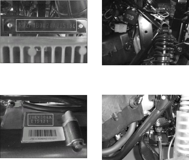
1.4 SERIAL NUMBER
(For YXL 150, EXL 150 / EXL 150(2004 two-passengers) and CXL 150 in this service manual)
The frame serial number is stamped on the front of the frame.
The engine serial number is stamped on the left side of the crankcase.
Frame serial number |
Side frame serial number --only in |
|
EXL 150 / 150 (2004 two-passengers) |
Engine serial number |
RXL / EXL150 (Viper. St) |
4
1.5 TORQUE VALUES
STANDARD
● 5 mm bolt and nut |
5 |
N.m (3.5 lbf.ft) |
● 6 mm bolt and nut |
10 |
N.m (7.2 lbf.ft) |
● 8 mm bolt and nut |
22 N.m (16 lbf.ft) |
|
●10 mm bolt and nut |
35 N.m (25 lbf.ft) |
|
●12 mm bolt and nut |
55 N.m (40 lbf.ft) |
|
ENGINE
● Cylinder head nut |
28 N.m (20.7 lbf.ft) |
|
● Spark plug |
12 |
N.m (8.9 lbf.ft) |
● Cylinder head bolt |
20 N.m (14.8 lbf.ft) |
|
● Alternator bolt |
8 |
N.m (5.9 lbf.ft) |
FRAME
● Handlebar upper holder bolt |
24 N.m (17.7 lbf.ft) |
|
● Throttle housing cover screw |
4 |
N.m (2.9 lbf.ft) |
● Steering shaft nut |
50 N.m (36.9 lbf.ft) |
|
● Steering shaft holder bolt |
33 N.m (24 lbf.ft) |
|
● Wheel rim bolt |
18 N.m (13.3 lbf.ft) |
|
● Tie rod lock nut |
35 N.m (25.8 lbf.ft) |
|
● King pin nut |
40 N.m (29 lbf.ft) |
|
● Handlebar lower holder nut |
40 N.m (29.5 lbf.ft) |
|
● Front wheel bolt |
24 N.m (17.7 lbf.ft) |
|
● Front axle castle nut |
40-60 N.m (30-45 lbf.ft) |
|
● Front brake arm nut |
4 |
N.m (3.0 lbf.ft) |
● Rear brake arm nut |
7 |
N.m (5.2 lbf.ft) |
● Rear axle castle nut |
40-60 N.m (30-45 lbf.ft) |
|
● Rear wheel bolt |
24 N.m (17.7 lbf.ft) |
|
● Exhaust muffler mounting bolt |
30 N.m (22.1 lbf.ft) |
|
● Engine hanger bolt |
30 |
N.m ( 22 lbf.ft) |
● Rear axle holder bolt |
90 N.m (65 lbf.ft) |
|
● Swing arm pivot nut |
90 N.m (65 lbf.ft) |
|
● Rear shock absorber mounting nut |
45 N.m (33 lbf.ft) |
|
5
2. MAINTENANCE
2.1 MAINTENANCE DATA |
2.8 IDLE SPEED |
2.2 MAINTENANCE SCHEDULE |
2.9 DRIVE CHAIN |
2.3 FUEL TUBLE |
2.10 BRAKE SYSTEM |
2.4 THROTTLE OPERATION |
2.11 WHEELS AND TIRES |
2.5 THROTTLE CABLE AJUSTMENT |
2.12 STEERING SYSTEM |
2.6 AIR CLEANER |
2.13 TOE-IN |
2.7 SPARK PLUG |
2.14 GEAR OIL |
2.1 MAINTENANCE DATA
SPECIFICATION
SPARK PLUG
SPARK PLUG CAP |
0.6-0.7 mm |
RECOMMENDED SPARK PLUGS |
|
THROTTLE LEVER FREE PLAY |
5-10 mm |
IDLE SPEED |
1600±100rpm |
BRAKE LEVER FREE PLAY |
15-25 mm |
DRIVE CHAIN SLACK |
10-25 mm |
TOE-IN |
5±10 mm |
TORQUE VALUES |
|
|
SPARK PLUG |
12-19 N.m |
|
TIE-ROD LOCK NUT |
35-43 N.m |
|
ENGINE OIL |
Viscosity: SAE 10W-40 |
|
API service classification SF or SG |
||
|
||
GEAR LUBRICATION OIL |
SAE 90 |
6
2.2 MAINTENANCE SCHEDULE
The maintenance internals in the follow table is based upon average riding, conditions. Riding in unusually
dusty areas, require more frequent servicing.
|
|
INITIAL SERVICE |
REGULAR SERVICE |
EVERY YEAR |
|
|
(First week) |
(Every 30 operating days) |
|
|
FUEL LINE |
I |
|
I |
|
THROTTLE OPERATION |
I |
I |
|
|
AIR CLEANER |
|
C |
|
|
SPARK PLUG |
|
I |
|
|
CARBURETOR IDLE |
I |
I |
|
|
SPEED |
|
|
|
|
DRIVE CHAIN |
I, L |
I, L |
|
|
BRAKE SHOE WEAR |
|
|
I |
|
BRAKE SYSTEM |
I |
I |
|
|
NUT, BOLT, FASTENER |
I |
I |
|
|
WHEEL/TIRES |
I |
I |
|
|
STEERING SYSTEM |
|
|
I |
|
SUSPENSION SYSTEM |
|
|
I |
|
GEAR OIL |
|
|
R |
|
ENGINE OIL |
R |
I |
R |
|
ENGINE OIL FILTER |
C |
|
C |
Note – I: Inspect and Clean, Adjust, Lubricate or Replace, if necessary |
|
|||
|
C: Clean |
L: Lubricate |
R: Replace |
|
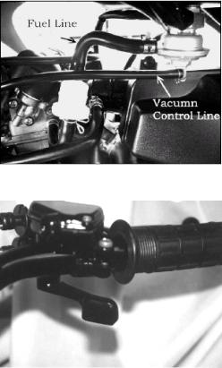
2.3 FUEL TUBE
Inspect the fuel lines for deterioration, damage or leakage and replace if necessary.
2.4 THROTTLE OPERATION
Inspect for smooth throttle lever full opening and automatic full closing in all steering positions. Inspect if there is no deterioration, damage or kink in the throttle cable, replace it if necessary.
Check the throttle lever, free play is 5-10 mm at the tip of the throttle lever.
Disconnect the throttle cable at the upper end. Lubricate the cable with commercially lubricant to prevent premature wear.
7

2.5 THROTTLE CABLE ADJUSTMENT
Slide the rubber cap of the adjuster off the throttle Housing, loosen the lock nut and adjust the free play of the throttle lever by turning the adjuster on
the throttle housing. Inspect the free play of the throttle lever.
2.6 AIR CLEANER
Unscrew the air cleaner cover screws. Remove the air cleaner case cover.
Pull out the air filter element from the air cleaner case. Wash the element in non-flammable solvent, squeeze out the solvent thoroughly.
Let it dry.
Soak the filter element in gear oil and then squeeze out the excess oil.
Install the element into air cleaner in the reverse order of removal.
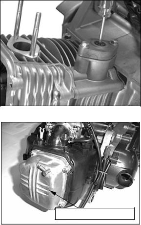
2.7 SPARK PLUG
This spark plug located at the front of the engine. Disconnect the spark plug cap and unscrew
the spark plug.
Check the spark plug electrodes for wear. Change a new spark plug if the electrodes and insulator tip appear unusually fouled or burned. Discard the spark plug if there is apparent wear or if the insulator is cracked or chipped.
The spark plug gap shall keep in 0.6-0.7mm.
With the sealing washer attached, thread the
spark plug in by hand to prevent crosses threading.
Tighten the spark plug with 12-19 N.m
2.8 IDLE SPEED
Connect an engine speed meter.
Warm up the engine, 10 minutes are enough.
Turn the idle-speed adjust screw on the carburetor to obtain the idle speed. “Turn in” (clockwise) will get higher speed. “Turn out” (counter clockwise) will get lower speed.
IDLE SPEED: 1700±100 rpm
8
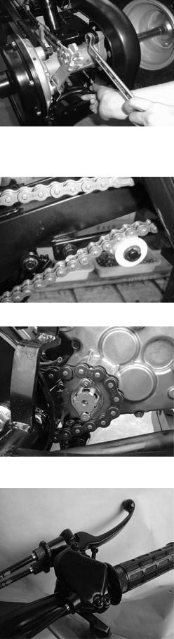
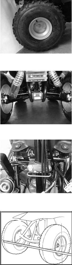
2.9 DRIVE CHAIN
Stop the ATV and shift the transmission into neutral. Measure the drive chain slack midway between the sprockets.
Chain slack =15~25mm (5/8~1 inch)
Adjust the chain slack.
Loosen the lock nuts and turn drive chain adjusting nuts until get the correct slack.
Tighten the axle holder bolts.
Torque = 90N.m (65 lbf.ft)
If your ATV has the tensioner inside the drive chain. You don't need to follow the procedure of chain slack adjustment. The drive chain will be adjusted by tensioner.
When the drive chain becomes very dirty, it should be removed, cleaned and lubricated by specify lubricator. Using commercial chain lubricant to lubricate the drive chain.
Clean the drive chain with kerosene and wipe it dry. Inspect the drive chain for possible wear or damage. Replace the chain, if it is worn excessively or damaged.
Inspect the sprocket teeth, if it is excessive wear or damage, replace it.
2.10 BRAKE SYSTEM
Inspect the front brake lever and cable for excessive play or other damage.
Replace or repair if necessary.
Measure the free play of the brake lever at the end of the brake lever. The standard of free play is 15-25 mm.
(The right side picture is for YXL 150)
9
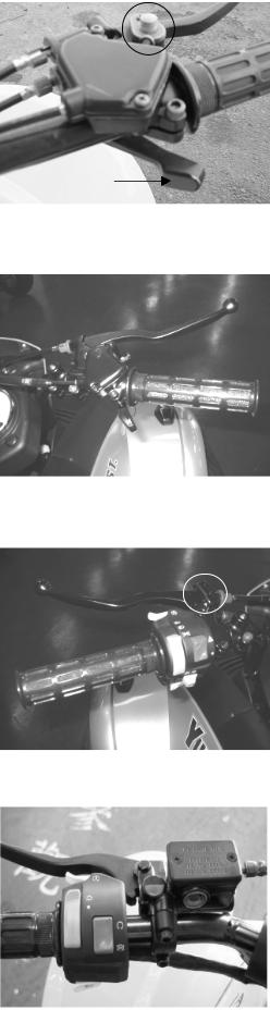
(The right side picture is for CXL / RXL / EXL-150 they have a parking brake on the top of hand brake.)
Only for EXL 150 (2004 two-passengers) / EXL-150 (VIPER)
Inspect the rear brake lever and cable for excessive play or other damage.
Replace or repair if necessary.
Measure the free play of the rear brake lever at the end of the lever. The standard is 10-20 mm.
(The right side picture is for YXL 150
/ EXL-150 (2004 two-passengers) / EXL-150 (VIPER))
(The right side picture is for CXL / RXL-150)
10
Adjust the free play of the rear brake lever by turning the adjuster on the rear axle.
(Only for YXL 150 / EXL 150 (2004 two-passengers), / EXL-150 (VIPER))
Because of the CXL / EXL / RXL-150 are both disc brake system, so they don’t need to adjust the free play. They will be discussed in chap10.
BRAKE SHOE WEAR
FRONT BRAKE
(The YXL / CXL / EXL / RXL 150 have the same model of front brake)
Release the front wheel and inspect the brake lining thickness.
Service Limit: 2.0mm(0.08 inch)
If either lining is worn beyond the service limit, replace Both brakes shoes.
REAR BRAKE
This system is for YXL / EXL 150 (2004 two-passengers) / EXL-150 (VIPER). Replace the brake shoes
if the indicator plate aligns with the brake index mark when the parking brake lever is applied.
11
2.11 WHEELS AND TIRES
Inspect the tire surfaces for cuts, nails or other sharp objects.
Check the tire surfaces at cold tire condition.
*The standard of tire pressure is on chap 1.
2.12 STEERING SYSTEM
Check the free play of the steering shaft with the front wheels, turned straight ahead.
When there is excessive play, inspect the tie-rod, kingpin bushing and ball joint.
STEERING SHAFT HOLDER BUSHING
Remove the front fender first.
Remove the steering shaft holder and check the steering shaft bushing for wears or damage.
If the bushing is worn or damaged, change a new one.
Grease the steering shaft bushing and install the parts in the reverse order of removal.
Torque: steering shaft holder bolt: 33 N.m (24 lbf.ft)
2.13 TOE-IN
Let the vehicle on level ground and the front wheels facing straight ahead.
Mark the centers of the tires to indicate the axle center height.
Measure the distance between the marks.
12

Carefully move the vehicle back, let the wheels have turned 180 °, so the marks on the tires are aligned with the axle center height.
Measure the distance between the marks. Calculate the difference in the front and rear measurements.
Toe-in: 5±10mm
If the toe-in is out of standard, adjust it by changing the length of the tie-rods equally by turning the tie-rod while holding the ball joint.
Tighten the lock nuts.
Torque: 35-43 N.m
2.14 GEAR OIL
Gear oil needs to be changed every year.
There is a gear oil release bolt at the rear of engine.
Unscrew this release bolt and can let the dirty oil flow out. (STEP1)
The re-add oil hole is on the engine case beside gearbox. (STEP2)
STEP1
STEP2
13
3. ENGINE REMOVE AND INSTALLATION
3.1 REPAIR CONDITION |
3.3 ENGINE INSTALLATION |
3.2ENGINE REMOVAL
3.1ENGINE SHALL BE REMOVED IN THE CONDITIONS OF NECESSARY REPAIRMENT OR ADJUSTMENT TO THE TRANSMISSION AND COMBUSTION SYSTEM ONLY
3.2ENGINE REMOVAL
Remove the seat, front fender and rear fender (see chapter 11). Remove the footrest. Remove the spark plug cap from the spark plug. Remove the exhaust muffler. Disconnect the carburetor cable by unscrew two screws on top of the carburetor.
Disconnect the wire connectors. There are three connectors for carburetor auto-choke, starter motor and generator respectively.
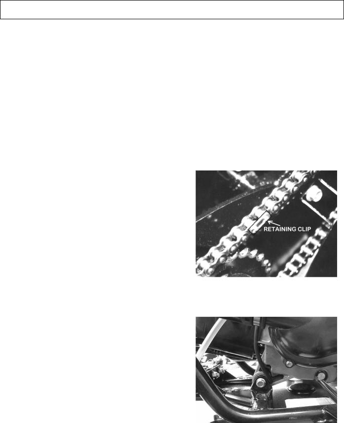
Remove the drive chain cover.
Remove the drive chain retaining clip and master link, and remove the drive chain.
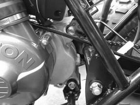
Remove the engine hanger bolts under the engine.
Remove the three bolts and air cleaner together.
14
3.3 ENGINE INSTALLATION
Engine installation is essentially the reverse order of removal. The torque of engine hanger bolt is 30 N.m Route the wires and cable in reverse order properly.
15
4.CYLINDER HEAD / VALVES
4.1 SERVICE INFORMATION |
4.4 CYLINDER HEAD REMOVAL |
4.2 TROUBLESHOOTING |
4.5 CYLINDER HEAD INSTALLATION |
4.3 CAMSHAFT COMPOSITION REMOVAL |
|
4.1 SERVICE INFORMATION
GENERAL
This section describes cylinder head, valves, camshaft and the other parts maintenance. The engine must be removed from the frame to service cylinder head. Camshaft lubrication oil is fed to the cylinder head through an oil orifice in the engine case. Before installing the cylinder head be sure the orifice is not clogged and the gasket, O-ring and dowel pins are in place.
SPECIFICATIONS
ITEM |
|
STANDARD |
SERVICE LIMIT |
|
|
|
|
|
|
CYLINDER COMPRESSION |
|
12±0.5 kg/cm2 |
-------- |
|
CAM LOBE HEIGHT |
IN |
29.795 |
29.395 |
|
|
|
|
||
EX |
29.560 |
29.160 |
||
|
||||
|
|
|
|
|
ROCKER ARM I.D. |
|
10.000-10.018 |
10.10 |
|
|
|
|
|
|
ROCKER ARM SHAFT O.D. |
|
9.972-9.987 |
9.91 |
|
|
|
|
|
|
CYLINDER HEAD WARPAGE |
|
-------- |
0.05 |
|
|
|
|
|
|
VALVE SPRING FREE LENGTH |
IN |
32.3 |
31.2 |
|
|
|
|
||
OUT |
35.0 |
34.1 |
||
|
||||
|
|
|
|
|
VALVE STEM O.D. |
IN |
4.975-4.990 |
4.90 |
|
|
|
|
||
EX |
4.955-4.970 |
4.90 |
||
|
||||
|
|
|
|
|
VALVE GUIDE I.D. |
IN/EX |
5.000-5.012 |
5.30 |
|
|
|
|
|
|
STEM-TO-GUIDE CLEARANCE |
IN |
0.010-0.037 |
0.08 |
|
|
|
|
||
EX |
0.030-0.057 |
0.10 |
||
|
||||
|
|
|
|
|
VALVE SEAT WIDTH |
IN |
1.0 |
1.8 |
|
|
|
|
||
EX |
1.0 |
1.8 |
||
|
||||
|
|
|
|
TORQUE VALUES
Cylinder head bolts |
8 |
~ 12 n-m (0.8 ~ 1.2 kg-m) |
Camshaft holder flange nuts |
20 ~ 24 n-m (2.0 ~ 2.4 kg-m) |
|
Tappet adjusting nut |
9 |
~ 12 n-m (0.9 ~ 1.2 kg-m) |
16

4.2 TROUBLE SHOOTING
Engine top-end problems usually affect engine performance. These problems can be diagnosed by a compression test, or by tracing engine noise to the top end with a sounding rod or stethoscope.
LOW COMPRESSION
Valve
Incorrect valve adjustment
Worn or damaged valve seats
Burned or bent valve
Incorrect valve timing
Weak valve spring
Cylinder head
Leaking or damaged head gasket
Warped or cracked cylinder head
Faulty cylinder or piston
Excessive noise
Incorrect valve adjustment
Sticking valve or broken valve spring
Worn or damaged rocker arm or camshaft
Worn or damaged cam chain
Worn or damaged cam chain tensioner
Worn cam sprocket teeth
Excessive smoke
Damaged valve stem seal
Faulty cylinder or piston rings
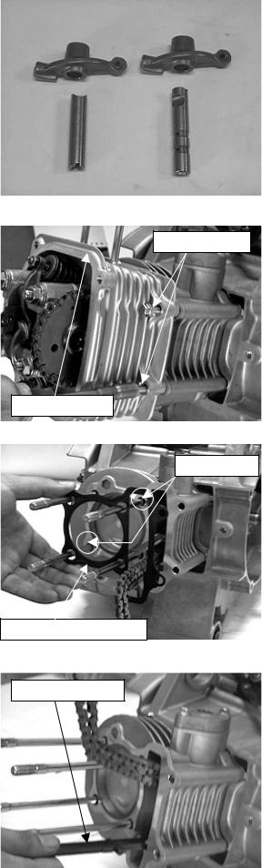
4.3 CAMSHAFT COMPOSITION REMOVAL
Remove the rubber tube of gas waste recovery. |
RUBBER TUBE |
|
|
|
|
|
|
|
|
|
|
GAS WASTE RECOVERY
Remove the cylinder head cover.
CYLINDER HEAD COVER
17

Remove the air cleaner and carburetor.
Remove the inlet pipe assy.
Remove the shroud compositions.
Relax the cam chain adjuster screw.
Remove the screw and O-ring and tighten the cam chain adjusting bolt with clockwise direction.
Remove the nuts and washers.
Remove the camshaft holder and dowel pins.
Relax the camshaft gear from cam chain and remove the camshaft.
CARBURATOR
SHROUD COMPOSITIONS |
|
INLET PIPE ASSY |
|
|
|
CAM CHAIN ADJUSTING BOLT
CAM CHAIN ADJUSTER SCREW
CAMSHAFT HOLDER
NUTS
CAMSHAFT
CAMSHAFT GEAR
18
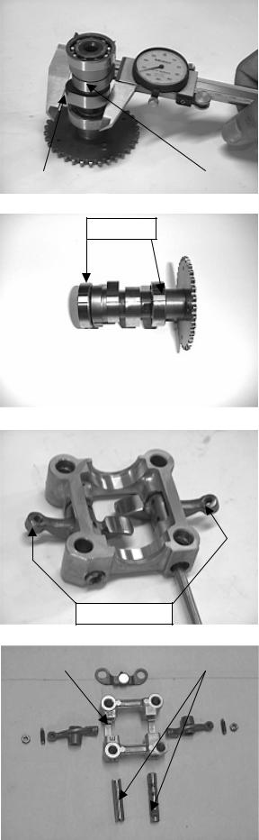
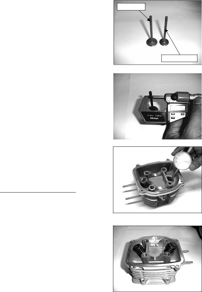
INSPECTION
Inspect the cam lobes surface and height of cam lobes for wear or damage.
SERVICE LIMIT: IN 29.395 mm
EX 29.160 mm
Inspect the camshaft and bearings for wear or damage and replace them if necessary.
Screw a 5mm bolt into the rocker arm shaft threaded end. Pull on the bolt to remove the shafts and rocker arms.
Inspect the camshaft holder, rocker arms and rocker arm shafts for wear or damage.
CAM |
|
LOBES |
|
|
|
BEARINGS
ROCKER ARMS
CAMSHAFT HOLDER |
|
ROCKER ARM SHAFTS |
|
|
|
19
Measure the I.D. of each rocker arm.
SERVICE LIMIT: 10.10 mm
Measure the O.D. of each rocker arm shaft.
SERVICE LIMIT: 9.91 mm
4.4 CYLINDER HEAD REMOVAL
Remove the flange bolts and cylinder head. |
FLANGE BOLTS |
|
CYLINDER HEAD
Remove the cylinder head gasket and dowel pins.
DOWEL PINS
CYLINDER HEAD GASKET
Remove the cam chain guide.
CAM CHAIN GUIDE
20
CYLINDER HEAD DISASSEMBLY
Remove the valve cotters, spring retainers and valve springs with a valve spring compressor.
INSPECTION
Clean off all carbon deposits from the combustion chamber.
Check the spark plug hole and valve area for cracks.
Measure the cylinder head diagonally for warpage with a straight edge and feeler gauge.
SERVICE LIMIT: 0.05 mm
Measure the free length of the inner and outer valve springs.
SERVICE LIMITS: Inner 31.2 mm Outer 34.1 mm
INNER VALVE
OUTER VALVE
21
Inspect each valve for turning, burning, scratches or abnormal stems wear.
Check the valve movement in the guide. Measure and record each valve stem O.D.
SERVICE LIMITS: 4.90 mm
Measure and record the valve guide I.D.
SERVICE LIMITS: IN / EX 5.30 mm
Calculate the stem-to-guide clearance.
SERVICE LIMITS: IN |
0.08 mm |
EX |
0.10 mm |
NOTE: If the stem-to-guide clearance exceeds the service limits, determine if a new guide with standard dimensions would bring the clearance within tolerance.
If so, replace guides as necessary and ream to fit. If the valve guide is replaced, the valve guide is replaced; the valve seat must be refaced.
CYLINDER HEAD ASSEMBLY
Lubricate each valve stem with oil. Insert the valves into guides.
Install the valve springs, retainers and the cotters.
NOTE: To prevent loss of tension, don’t compress the valve springs more than necessary.
INLET VALVE
EXHAUST VALVE
22
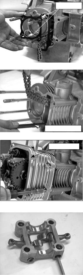
INSTALLATION
Install the new gasket and dowel pins.
Install the cam chain guide.
Install the cylinder head.
CAMSHAFT COMPOSITION INSTALLATION
Install the rocker arms and rocker arm shafts into the camshaft holder.
DOWEL PINS
 CAM CHAIN GUIDE
CYLINDER HEAD
23
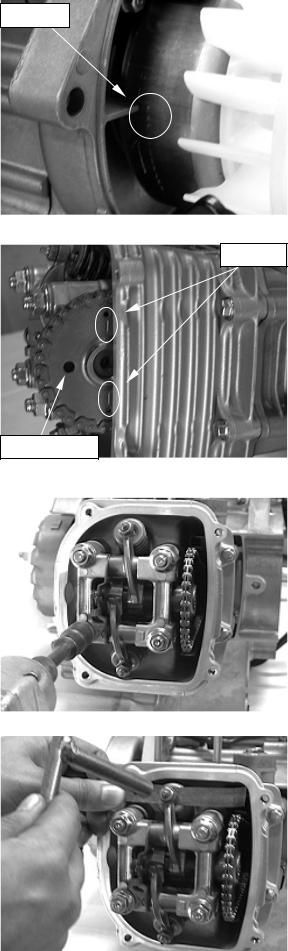
Align the “T” mark on the flywheel with the index mark on the alternator cover by turning the flywheel counter - clockwise.
Position the camshaft gear with cam chain so that its “I” mark aligns with the cylinder head surface and the circle hole forwards front.
Install the dowel pins and camshaft holder. Tighten the washers and nuts.
TORQUE: 20 n-m (2.0 kg-m)
Adjust the clearance between the rocker arm and valve stem by applying a feeler gauge.
STANDARD VALVE: 0.08 mm
“T” MARK
“I” MARK
CIRCLE HOLE
24
Relax the cam chain-adjusting bolt with counterclockwise direction and install the o-ring and screw.
Install the cylinder head cover.
CYLINDER HEAD COVER
25
5. LUBRICATION
5.1 SERVICE INFORMATION |
5.4 ENGINE OIL & FILTER CHANGE |
5.2 TROUBLESHOOTING |
5.5 OIL PUMP |
5.3 ENGINE OIL LEVEL |
|
5.1 SERVICE INFORMATION
GENERAL
This section describes inspection and replacement of the engine oil, oil filter screen and assembly of the oil pump.
Fill the oil pump with clean oil when reassembling the pump.
SPECIFICATION |
|
ENGINE OIL CAPACITY |
0.8-1.0 liter |
API service classification: SF or SG |
ENGINE OIL RECOMMENDATION |
|
VISCOSITY: SAE 20w-40 |
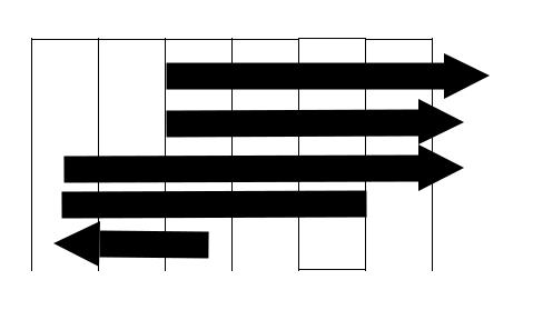
When the average temperature in your riding area is within the indicated range, you should use the other engine oil viscosities that are shown in the chart.
ENGINE OIL VISCOSITIES
SAE 20W-50
SAE 20W-40
SAE 10W-40
SAE 10W-30
|
|
|
SAE 5W |
|
|
|
|
|
|
|
|
|
|
|
|
|
|
|
|
|
|
||
|
-20 |
-10 |
0 |
10 |
20 |
30 |
40 o C |
||||
|
|
|
|
|
|
|
|
|
|
||
|
ITEM |
|
|
|
STANDARD |
|
|
|
SERVICE LIMIT |
||
OIL PUMP |
COVER-TO-ROTOR CLEARANCE |
|
---------- |
|
|
|
0.12 |
||||
|
ROTOR TIP CLEARANCE |
|
|
---------- |
|
|
|
0.12 |
|||
|
|
|
|
|
|
|
|
||||
|
END CLEARANCE |
|
|
0.05 – 0.10 |
|
|
0.2 |
||||
|
|
|
|
|
|
|
|
|
|
|
|
TORQUE VALUE |
|
|
|
|
|
|
|
|
|
||
OIL DRAIN BOLT |
20-30 n-m |
(2.0~3.0 kg-m) |
|
|
|
|
|
|
|||
26
5.2 TROUBLESHOOTING
Oil lever too low-high oil consumption
Normal oil consumption.
External oil leaks.
Oil not changed often enough.
Worn piston rings.
Faulty heat gasket.
Oil contamination
Worn piston rings.
Faulty heat gasket.
Oil or filter not changed often enough.
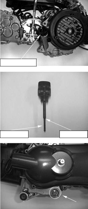
5.3 ENGINE OIL LEVEL
Place the engine on the level plane.
Check the oil level with the oil level gauge, but do not screw it in when making this check.
OIL LEVEL GAUGE
Add the recommended oil up to the upper level if the oil level is below or near lower level line on the gauge.
LOWER |
UPPER LEVEL |
5.4 ENGINE OIL & FILTER CHANGE
Remove the oil filter cap and the oil drain bolt. NOTE: Drain the oil while the engine is warm to ensure complete draining.
27 |
OIL DRAIN |
|
|
|
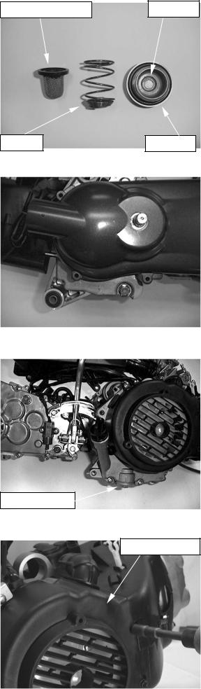
Remove the oil filter cap, spring and oil filter screen. Check the O-ring for damage or fatigue.
Install a new oil filter screen and spring then install the cap.
Install the oil drain bolt with sealing washer.
TORQUE: 20~30 n-m (2.0 ~ 3.0 kg-m)
Fill the crankcase with recommended oil.
ENGINE OIL CAPACITY: 0.8 liter at draining.
Install the oil filter cap. Install the oil level gauge.
Start the engine and let it idle speed for 2 or 3 minutes. Stop the engine and check that the oil level at the upper line on the gauge. Make sure there is no oil leaks.
5.5 OIL PUMP REMOVAL
Remove the fan cover assy.
OIL FILTER SCREEN
SPRING
OIL FILTER CAP
OIL FILTER
O-RINING
FAN COVER ASSY.
28

Remove the cooling fan composition. |
COOLING FAN COMPOSITION |
|
|
Remove the A.C.G generator assy. |
A.C.G GENERATOR ASSY |
Remove the right crankcase cover.
CRANKCASE COVER
Remove the starting clutch outer and gear assy. |
STARTING CLUTCH OUTER |
29 |
STARTING CLUTCH GEAR |

Remove the flange bolts and oil separator.
Remove the oil pump chain and oil pump driven sprocket.
Remove the oil pump assy.
Disassemble the oil pump.
OIL SEPARATOR
FLANGE BOLTS
OIL PUMP CHAIN
OIL PUMP DRIVEN SPROCKET
OIL PUMP ASSY.
OIL PUMP ASSY.
30
 Loading...