


Unison Paradigm ACP
Table of contents
 Loading...
Copyright © Electronic Theatre Controls, Inc.
All Rights reserved.
Product information and specifications subject to change.
Part Number:
7180M1230-2.1.2
Rev A
Released: 2014-07
Architectural Control Processor
Configuration Manual
2.1

ETC
®
, Unison
®
, and Unison Paradigm
®
, are either registered trademarks or trademarks of Electronic Theatre
Controls, Inc. in the United States and other countries. Echelon
®
, LonWorks
®
, and LON
®
are either registered
trademarks or trademarks of the Echelon Corporation.
All other trademarks, both marked and not marked, are the property of their respective owners.
ETC intends this document, whether printed or electronic, to be provided in its entirety.

Paradigm Architectural Control Processor Configuration Manual i
Table of Contents
Introduction . . . . . . . . . . . . . . . . . . . . . . . . . . 1
Standard Performance Features . . . . . . . . . . . . . . . . . . . . . . . . .1
Warnings and Notice Conventions . . . . . . . . . . . . . . . . . . . . . . .2
Contacting ETC . . . . . . . . . . . . . . . . . . . . . . . . . . . . . . . . . . . . . .3
Overview . . . . . . . . . . . . . . . . . . . . . . . . . . . . . . . . . . . . . . . . . . . . . .4
Paradigm System Components . . . . . . . . . . . . . . . . . . . . . . . . . .4
Paradigm ACP Features . . . . . . . . . . . . . . . . . . . . . . . . . . . . . . .4
Installation Environment Requirements . . . . . . . . . . . . . . . . . . . . . . .7
Installation and User Interface Overview . . . 8
Install the Paradigm ACP . . . . . . . . . . . . . . . . . . . . . . . . . . . . . . . . . .9
System Status . . . . . . . . . . . . . . . . . . . . . . . . . . . . . . . . . . . . . .10
User Interface Overview. . . . . . . . . . . . . . . . . . . . . . . . . . . . . . . . . .11
LCD Display. . . . . . . . . . . . . . . . . . . . . . . . . . . . . . . . . . . . . . . .11
Wake . . . . . . . . . . . . . . . . . . . . . . . . . . . . . . . . . . . . . . . . . . . . .11
Touch Wheel . . . . . . . . . . . . . . . . . . . . . . . . . . . . . . . . . . . . . . .11
Enter . . . . . . . . . . . . . . . . . . . . . . . . . . . . . . . . . . . . . . . . . . . . .12
Back. . . . . . . . . . . . . . . . . . . . . . . . . . . . . . . . . . . . . . . . . . . . . .12
Control Menu Shortcut. . . . . . . . . . . . . . . . . . . . . . . . . . . . . . . .12
Alpha-Numeric Button Pad . . . . . . . . . . . . . . . . . . . . . . . . . . . .12
Removable Media . . . . . . . . . . . . . . . . . . . . . . . . . . . . . . . . . . .14
Ethernet . . . . . . . . . . . . . . . . . . . . . . . . . . . . . . . . . . . . . . . . . . .14
Reset Switch . . . . . . . . . . . . . . . . . . . . . . . . . . . . . . . . . . . . . . .15
Paradigm ACP Basic Navigation . . . . . . . . 16
Status Display . . . . . . . . . . . . . . . . . . . . . . . . . . . . . . . . . . . . . . . . .17
DRd Dimming Rack Status Display . . . . . . . . . . . . . . . . . . . . . .17
Arch Control Status Display. . . . . . . . . . . . . . . . . . . . . . . . . . . .18
Status / Error Messages. . . . . . . . . . . . . . . . . . . . . . . . . . . . . . . . . .19
Status / Error Messages Generated by the Paradigm ACP. . . .20
Status / Errors Messages Generated by the DRd Dimming Engine
21
Menu Navigation . . . . . . . . . . . . . . . . . . . . . . . . . . . . . . . . . . . . . . .22
Programming . . . . . . . . . . . . . . . . . . . . . . . 23
About Menu . . . . . . . . . . . . . . . . . . . . . . . . . . . . . . . . . . . . . . . . . . .24
About Dimmer . . . . . . . . . . . . . . . . . . . . . . . . . . . . . . . . . . . . . .24
DMX Level Data. . . . . . . . . . . . . . . . . . . . . . . . . . . . . . . . . . . . .24
Version Info . . . . . . . . . . . . . . . . . . . . . . . . . . . . . . . . . . . . . . . .26
Project Information. . . . . . . . . . . . . . . . . . . . . . . . . . . . . . . . . . .26
Statistics . . . . . . . . . . . . . . . . . . . . . . . . . . . . . . . . . . . . . . . . . .26
View Message Log . . . . . . . . . . . . . . . . . . . . . . . . . . . . . . . . . .28
System Network. . . . . . . . . . . . . . . . . . . . . . . . . . . . . . . . . . . . .28
Stations and LonWorks . . . . . . . . . . . . . . . . . . . . . . . . . . . . . . .28
Dimming Setup Menu. . . . . . . . . . . . . . . . . . . . . . . . . . . . . . . . . . . .30

ii Paradigm Architectural Control Processor Configuration Manual
Dimmer Setup . . . . . . . . . . . . . . . . . . . . . . . . . . . . . . . . . . . . . .30
Patch By DMX Start. . . . . . . . . . . . . . . . . . . . . . . . . . . . . . . . . .34
Patch Dimmers . . . . . . . . . . . . . . . . . . . . . . . . . . . . . . . . . . . . .35
Emergency Setup . . . . . . . . . . . . . . . . . . . . . . . . . . . . . . . . . . .36
Quick Rack Setup . . . . . . . . . . . . . . . . . . . . . . . . . . . . . . . . . . .39
Arch Setup Menu . . . . . . . . . . . . . . . . . . . . . . . . . . . . . . . . . . . . . . .41
LonWorks Connections . . . . . . . . . . . . . . . . . . . . . . . . . . . . . . .41
Assign Processor / IP . . . . . . . . . . . . . . . . . . . . . . . . . . . . . . . .43
Date/Time/Location . . . . . . . . . . . . . . . . . . . . . . . . . . . . . . . . . .44
Preferences . . . . . . . . . . . . . . . . . . . . . . . . . . . . . . . . . . . . . . . .45
Data Loss and Power On. . . . . . . . . . . . . . . . . . . . . . . . . . . . . .47
DMX Settings. . . . . . . . . . . . . . . . . . . . . . . . . . . . . . . . . . . . . . .48
Dimming Control Menu. . . . . . . . . . . . . . . . . . . . . . . . . . . . . . . . . . .49
Set Levels . . . . . . . . . . . . . . . . . . . . . . . . . . . . . . . . . . . . . . . . .49
Dimmer Check . . . . . . . . . . . . . . . . . . . . . . . . . . . . . . . . . . . . . .50
Release Set Levels . . . . . . . . . . . . . . . . . . . . . . . . . . . . . . . . . .50
Arch Control Menu . . . . . . . . . . . . . . . . . . . . . . . . . . . . . . . . . . . . . .51
Presets. . . . . . . . . . . . . . . . . . . . . . . . . . . . . . . . . . . . . . . . . . . .51
Control Channels . . . . . . . . . . . . . . . . . . . . . . . . . . . . . . . . . . . .52
Groups . . . . . . . . . . . . . . . . . . . . . . . . . . . . . . . . . . . . . . . . . . . .53
Walls . . . . . . . . . . . . . . . . . . . . . . . . . . . . . . . . . . . . . . . . . . . . .53
Sequences. . . . . . . . . . . . . . . . . . . . . . . . . . . . . . . . . . . . . . . . .54
Macros . . . . . . . . . . . . . . . . . . . . . . . . . . . . . . . . . . . . . . . . . . . .54
Overrides . . . . . . . . . . . . . . . . . . . . . . . . . . . . . . . . . . . . . . . . . .55
Clear Arch Output . . . . . . . . . . . . . . . . . . . . . . . . . . . . . . . . . . .55
File Operations Menu . . . . . . . . . . . . . . . . . . . . . . . . . . . . . . . . . . . .56
Save Rack Configurations . . . . . . . . . . . . . . . . . . . . . . . . . . . . .56
Save Dimming Configuration . . . . . . . . . . . . . . . . . . . . . . . . . . .57
Load Dimming Configuration . . . . . . . . . . . . . . . . . . . . . . . . . . .57
Save Arch Configuration . . . . . . . . . . . . . . . . . . . . . . . . . . . . . .59
Load Architectural Configuration . . . . . . . . . . . . . . . . . . . . . . . .60
Restore Defaults . . . . . . . . . . . . . . . . . . . . . . . . . . . . . . . . . . . .61
Update Firmware . . . . . . . . . . . . . . . . . . . . . . . . . . . . . . . . . . . .62
Save LCD Files . . . . . . . . . . . . . . . . . . . . . . . . . . . . . . . . . . . . .63
Save Log Files . . . . . . . . . . . . . . . . . . . . . . . . . . . . . . . . . . . . . .64
Archive Mismatch Warning . . . . . . . . . . . . . . . . . . . . . . . . . . . .65
Restricted Access Menu. . . . . . . . . . . . . . . . . . . . . . . . . . . . . . . . . .66
Login . . . . . . . . . . . . . . . . . . . . . . . . . . . . . . . . . . . . . . . . . . . . .66
Change Passcode . . . . . . . . . . . . . . . . . . . . . . . . . . . . . . . . . . .67
Default Access. . . . . . . . . . . . . . . . . . . . . . . . . . . . . . . . . . . . . .67
Timed Event Setup Menu . . . . . . . . . . . . . . . . . . . . . . . . . . . . . . . . .68
View/Edit Events . . . . . . . . . . . . . . . . . . . . . . . . . . . . . . . . . . . .68
Add New Event . . . . . . . . . . . . . . . . . . . . . . . . . . . . . . . . . . . . .70
Delete Event . . . . . . . . . . . . . . . . . . . . . . . . . . . . . . . . . . . . . . .71
Special Day Protect . . . . . . . . . . . . . . . . . . . . . . . . . . . . . . . . . .71
Service . . . . . . . . . . . . . . . . . . . . . . . . . . . . 72
Service and Maintenance. . . . . . . . . . . . . . . . . . . . . . . . . . . . . . . . .73
Replace a Paradigm ACP . . . . . . . . . . . . . . . . . . . . . . . . . . . . .73
Hardware Reset Switch . . . . . . . . . . . . . . . . . . . . . . . . . . . . . . .74

iii
Appendix A
Paradigm ACP Menu Flow Chart . . . . . . . . 75
Menu Flow Chart . . . . . . . . . . . . . . . . . . . . . . . . . . . . . . . . . . . . . . .76
Appendix B
Dimmer Specifications . . . . . . . . . . . . . . . . 83
Unison DRd Rack Compatible Modules . . . . . . . . . . . . . . . . . . . . . .83
Dimmer Module Defaults . . . . . . . . . . . . . . . . . . . . . . . . . . . . . . . . .86
Compatible Loads . . . . . . . . . . . . . . . . . . . . . . . . . . . . . . . . . . . . . .87
Dimmer Modes . . . . . . . . . . . . . . . . . . . . . . . . . . . . . . . . . . . . . . . . .89
Dimmer Properties . . . . . . . . . . . . . . . . . . . . . . . . . . . . . . . . . . . . . .92
1 Paradigm Architectural Control Processor Configuration Manual
Introduction
Welcome to the Paradigm Architectural Control Processor (P-ACP) Configuration Manual.
This manual contains information for user configuration and programming of the Paradigm
ACP when installed in a Unison DRd or ERn enclosure.
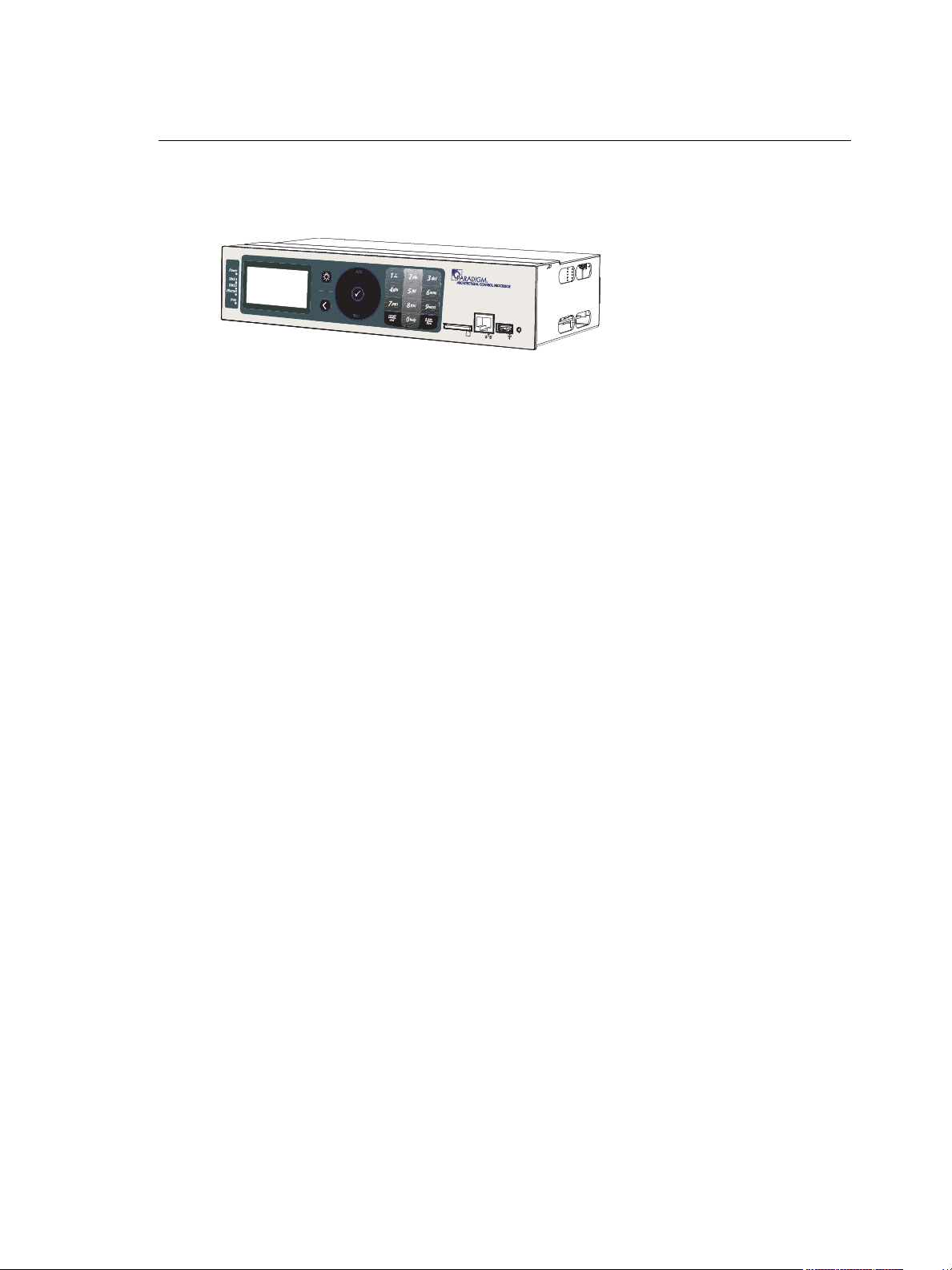
The Paradigm Architectural Control Processor (P-ACP) is an integrated hardware and
software solution for complete configuration and control of dimmers, LED fixtures, DMX-
based moving lights, conventional and architectural fixtures, and Heritage and Paradigm
control stations.
Paradigm, combined with Unison LightDesigner software, may be utilized universally in the
Unison DRd enclosure and the ERn processing enclosure to program and control
architectural and theatrical applications with straightforward integrated networking for both
NetConnect and Paradigm LinkConnect control networks.
The Paradigm ACP features a dynamic user interface with a touch wheel for easy menu
navigation, an alpha-numeric button pad for direct selection, and a bright, easy to read
graphic LCD. Additionally, a Secure Digital (SD) media card slot, integrated USB port for
use of a flash drive and an Ethernet port for PC connection and LightDesigner configuration
updates are provided.
The Paradigm ACP serves as the real time processor for incoming control signals from
other processors and control sources and transmits that information to the individual
dimmers and architectural control stations.
Standard Performance Features
• User configurable control signal loss behavior including: “hold last look” or “wait and
fade to off”.
• The timed event synchronization feature restores the proper timed event state based
on the current date and time after rebooting.
• Robust “highest takes precedence (HTP)” processing and support of multiple and
simultaneous external sources of information from presets, zones, DMX, and Ethernet.
• Supports up to 62 Heritage control stations over the LinkConnect control network. Up
to six of these stations may be Paradigm Touchscreen stations.
• All data is automatically stored to the built-in CompactFlash allowing rapid replacement
of a Paradigm ACP if needed.
• Built-in SD-card slot and USB port are provided for removable media (SD media card
or USB flash drive) allowing back up of the architectural and dimming configuration
files. Dimming configuration files are available only when the Paradigm ACP is installed
in a host DRd enclosure.
• Built-in real-time and astronomical time clock.
• Built-in Ethernet port for upload and modifications of configuration files from a
connected PC running Unison LightDesigner.

Introduction 2
Warnings and Notice Conventions
These symbols are used throughout this manual to alert you to danger or important
information:
Note:
Notes are helpful hints and information that are supplemental to the main text.
CAUTION:
A Caution statement indicates situations where there may be undefined or
unwanted consequences of an action, potential for data loss, or an equipment
problem.
WARNING:
A Warning statement indicates situations where damage may occur, people
may be harmed, or there are serious or dangerous consequences of an
action.
WARNING:
RISK OF ELECTRIC SHOCK! This warning statement indicates situations
where there is a risk of electric shock.

3 Paradigm Architectural Control Processor Configuration Manual
Contacting ETC
For questions about delivery of your Unison system, contact ETC Systems Group. For
general information, your most convenient resources are the references provided in this
manual. To search more widely try the ETC web site at www.etcconnect.com.
For technical questions about Unison rack systems, contact ETC Technical Services
directly at one of the offices listed below. Emergency service is available from all ETC
offices outside of normal business hours. When calling for assistance, please be near the
equipment for troubleshooting and have the following information handy:
• Your location and job name.
• A complete list of ETC equipment.
• A complete list of other installed products and components connected to the system
you are troubleshooting.
• DMX control source, if any.
Please email comments about this manual to: TechComm@etcconnect.com
Americas
ETC International
Technical Services Department
3031 Pleasant View Road
Middleton, WI 53562
800-775-4382 (USA, toll-free)
+1-608 831-4116
service@etcconnect.com
United Kingdom
Electronic Theatre Controls, Ltd.
Technical Services Department
26 - 28 Victoria Industrial Estate
Victoria Road,
London W3 6UU, UK
+44 (0)20 8896 1000
service@etceurope.com
Asia
ETC Asia, Ltd.
Technical Services Department
Room 1801, 18/F, Tower 1, Phase 1
Enterprise Square
9 Sheung Yuet Road
Kowloon Bay, Kowloon, Hong Kong
+852 2799 1220
service@etcasia.com
Germany
Electronic Theatre Controls, GmbH
Technical Services Department
Ohmstrasse 3
93607, Holzkirchen, Germany
+49 (80 24) 47 00-0
techserv-hoki@etcconnect.com
Introduction 4
Overview
Paradigm System Components
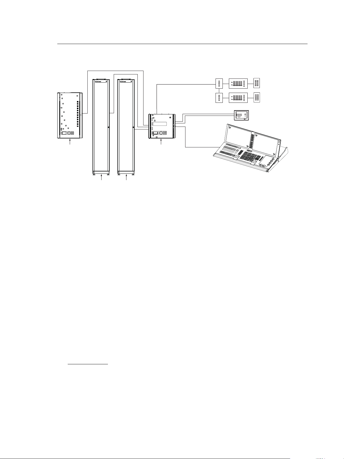
The Paradigm Architectural Control Processor (P-ACP) is one component of the Paradigm
control system. A Paradigm ACP is designed to fit in the bottom module slot of either a DRd
or ERn enclosure and provides an intuitive user interface into the Paradigm system. The
operational menus of the Paradigm ACP are slightly different when used in a DRd
enclosure due to menu content that is specific to dimming setup and dimming control
options, not relevant to the ERn processing operation.
The Paradigm ACP provides multiple control inputs into the Paradigm system including:
• NetConnect Ethernet networking (Net3 based on ESTA BSR E1.17 ACN, ESTA BSR
E1.31 streaming ACN protocols, and TCP/IP).
• ESTA DMX512A (up to two universes).
• EIA RS-232 serial.
• LinkConnect (Echelon
®
LonWorks
®
with LinkPower) networking.
• Multiple dry contact inputs and outputs.
The Paradigm ACP receives project configuration and programming data from Unison
LightDesigner software. LightDesigner is an easy to use graphical programming software
designed to simplify project setup and programming. LightDesigner provides users total
control of the system design and provides graphical simulation of programming before
loading into the Paradigm ACP.
Paradigm ACP Features
Configuration
Project programming and configuration are accomplished in LightDesigner software. Once
configured, the configuration is uploaded into the Paradigm ACP. You may edit
configurations live using the LightDesigner “Live Control” and “Live Edit” features.
Additional system operational setup, not specific to a project configuration, is accomplished
from the front panel of the ACP. When the Paradigm ACP is hosted by a DRd enclosure,
dimmer address and dimmer control specifications are accomplished at the Paradigm ACP,
not through the LightDesigner configuration file.
LinkPower
DMX input
to ERn rack
ETC Console
(for optional stage lighting)
LinkPower
Aux Power 24 Vdc
Preset 10
Preset 6
Preset 7
Preset 9
Preset 8
Preset 5
Preset 1
Preset 2
Preset 4
Preset 3
Preset 10
Preset 6
Preset 7
Preset 9
Preset 8
Preset 5
Preset 1
Preset 2
Preset 4
Preset 3
Preset 5
Preset 1
Preset 2
Preset 4
Preset 3
Preset 5
Preset 1
Preset 2
Preset 4
Preset 3
Preset 5
Preset 1
Preset 2
Preset 4
Macro Record
Sequence
Preset 3
Preset 5
Preset 1
Preset 2
Preset 4
Macro Record
Sequence
Preset 3
SENSOR+
SR48+
dimmer rack
Unison DRd12
rack enclosure
Unison ERn4
processing rack
Unison Paradigm
Touchscreen LCD
Eos Ti
console
Unison Heritage
Stations
SENSOR+
SR48+
dimmer rack
SYSTEMLORTNOCGNIHGIL T SYSTEMLORTNOCGNIHGIL T
power
feed
power
feed
power
feed
power
feed

5 Paradigm Architectural Control Processor Configuration Manual
Storage
The project configuration, after upload to the Paradigm ACP, is stored in non-volatile
CompactFlash
®
memory. When the Paradigm ACP is installed in a host DRd enclosure,
dimming configuration data is also stored in the dimming engine.
Backup
The Paradigm ACP front panel features a Secure Digital (SD) media card slot and a USB
port for use of a flash drive. Use any compatible removable media to backup your
configuration files. See “Removable Media”, page 14 for a list of compatible media.
Configuration files may include the dimming engine configuration, which is specific to a host
DRd enclosure, and the Paradigm configuration.
Additionally, an Ethernet port is provided for PC connection to the Paradigm ACP and its
connected Ethernet network. With LightDesigner open and connected to the Paradigm
ACP you can choose to retrieve and save a copy of the configuration file from the ACP to
a connected computer. Additionally, configuration updates can be uploaded from the PC to
the connected ACP.
Rack and System Feedback
The Paradigm ACP provides indicator feedback of DMX input and DMX output status,
controller power status, Ethernet status, and rack errors on LEDs visible from the front
panel of the processor with the rack door closed. Additional status information is provided
on the front panel of the Paradigm ACP display.
When the Paradigm ACP is installed in a host DRd enclosure, the default status display is
“Dimming Rack Status”. Rack status includes information pertaining to DMX addressing,
rack phase voltage, frequency settings, rack temperature and embedded dimming engine
software version number.
Clockwise rotation on the touch wheel changes the status display to “Arch Control Status”.
When the Paradigm ACP is installed in an ERn processing enclosure, this is the only status
display. “Arch Control Status” includes information pertaining to the Paradigm processor
including the processor name and IP address. In addition, the “Arch Control Status”
displays DMX port configuration, activity, host rack type and Paradigm software version
number.
Control Inputs
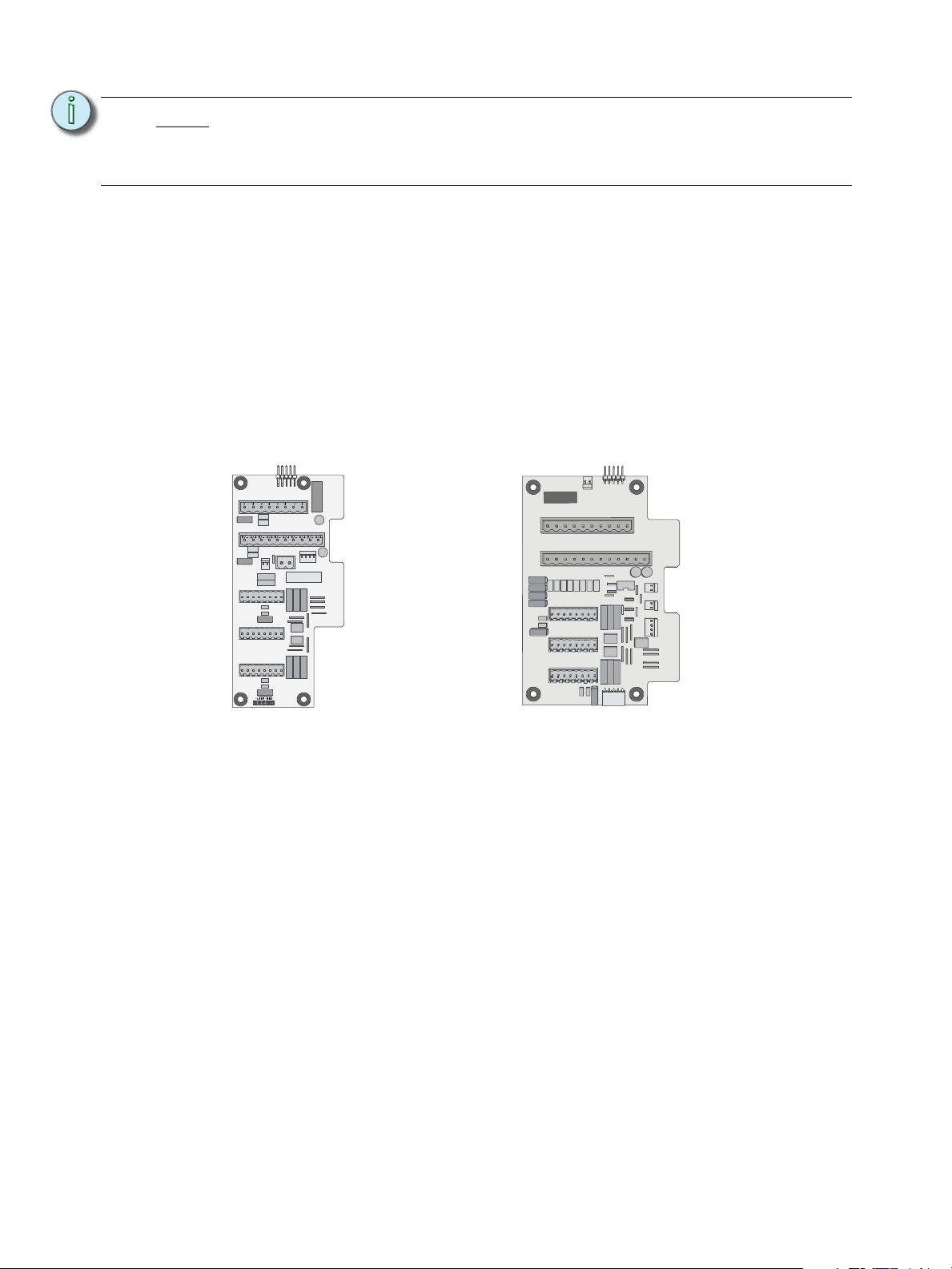
Left I/O
The left I/O board on the DRd and ERn enclosures provide a selection of control inputs into
the Paradigm control network which pertain specifically to the Paradigm ACP. All
connections are pluggable for ease of installation.
• RS-232 (serial) on a male 9 pin (D style) connector. This connection typically requires
a null modem (i.e. cross-over) cable between RS-232 sources without 3rd party signal
routing/repeating (e.g. A standard Windows
®
PC would require a null-modem cable to
interface with the left I/O board).
NO4
COM4
NO3
COM3
NO2
COM2
NO1
COM1
IN4
GND
IN3
GND
IN2
GND
IN1
GND
OUTPUTSINPUTS
J4
J5
7183B4605 REV C
© 2012 ETC, INC.
MADE IN THE U.S.A.
RS-232
J3
J2
ETHERNET
1
6
Ethernet
RS-232
1
6
J3
J2
J4
J5
7180B5626 Rev B
IN4
GND
IN3
GND
IN2
GND
IN1
GND
INPUTS
NO4
COM4
NO3
COM3
NO2
COM2
NO1
COM1
OUTPUTS
ERn left I/O board DRd left I/O board
Introduction 6
• Ethernet (IEEE 802.3) on an RJ45 female connector. This connection networks the
host Paradigm ACP with other ACPs and devices on the control network.
• Termination available for dry contact closures on 8 pin pluggable connectors:
• 4 electrically isolated inputs and 4 common wires
• 4 normally open outputs and 4 common wires
The Paradigm ACP utilizes the Paradigm LinkConnect (LinkPower) control network and
Ethernet (IEEE 802.3) to provide flexible control of dimming systems and architectural
control stations.
Right I/O
The right I/O board on the DRd and ERn enclosures provide a majority of the control inputs
into the system including:
• Auxiliary Power - provides 24 Vdc power to some Unison architectural control stations.
• LinkPower - station communication bus from the Paradigm ACP to the architectural
control stations.
• DMX (Digital Multiplex) - addresses up to 512 channels of control. In an ERn enclosure,
the Paradigm ACP supports two configurable DMX universes, individually configurable
for input or output. In a DRd enclosure, the Paradigm ACP supports only one universe
of DMX, selectable as an input or an output, and one dedicated DMX output. DMX
through connections are also provided.
Additional detail for connections found on the right I/O boards are detailed in the related
enclosure (DRd or ERn) installation documentation.
Note:
Check the pin-out of the connected RS-232 service to ensure correct pairing of
transmit and receive lines. The RS-232 cable (not supplied) should follow
common RS-232 pinout for a DB- 9 receptacle (pin 2 is RS-232 Rx, pin 3 is
RS-232 Tx, and pin 5 is ground).
SIGNAL DISTRO
RIDE THRU/BATT
J9
DUAL RACKS
LPS
APM
DMXB
AUX POWER
LON LINK / ECHO BUS
CDI
DMXA
B+ B- COM A+ A- COM
7183B4606 REV F © 2013 ETC, INC. MADE IN THE U.S.A.
B+ B- COM
COM PANIC
A+ A- COM
DMXB DMXA
SRC OFF END
DMX PASS-THRU
DRd right I/O ERn right I/O

7 Paradigm Architectural Control Processor Configuration Manual
Installation Environment Requirements
The Paradigm ACP is designed for use in a Unison DRd or ERn enclosure. The
environmental conditions for the Paradigm ACP should adhere to the requirements set for
the host enclosure. Reference the related enclosure Installation manual for complete
details.
• A clean (not dusty), temperature controlled environment with the following conditions:
• ambient temperature 32-104°F / 0-40°C
• ambient Humidity 30-90%, non-condensing
Installation is as simple as sliding the ACP module into the guided slots of the enclosure.
There are no wire terminations made directly to the Paradigm ACP, instead all wire
terminations are made to the host enclosure left and right I/O boards. Reference the related
DRd or ERn enclosure installation manual for termination details.
CAUTION:
HVAC systems must at all times maintain the specified ambient temperature at the
Unison enclosure.

1 Installation and User Interface Overview 8
Chapter 1
Installation and User Interface
Overview
This chapter contains the following sections:
• Install the Paradigm ACP . . . . . . . . . . . . . . . . . . . . . . . . . . . . .9
• User Interface Overview . . . . . . . . . . . . . . . . . . . . . . . . . . . . .11

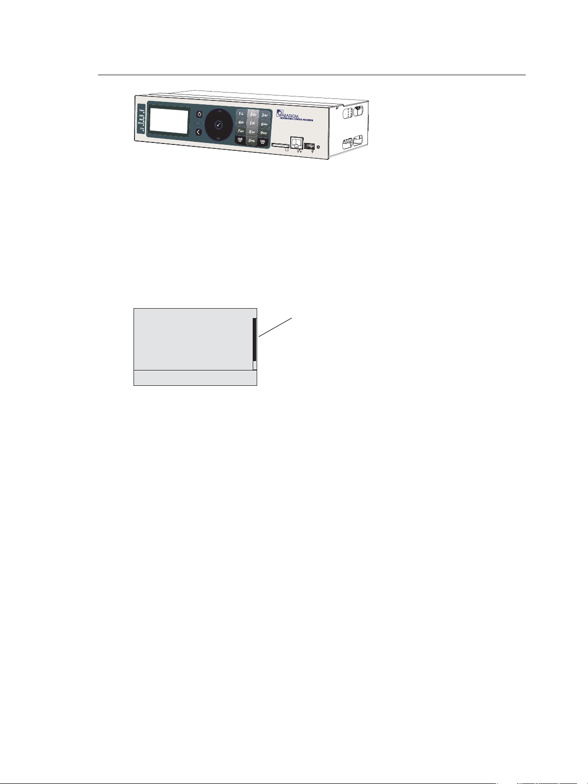
9 Paradigm Architectural Control Processor Configuration Manual
Install the Paradigm ACP
The Paradigm Architectural Control Processor (P-ACP) is designed to slide in the bottom
module slot of a Unison DRd or an ERn enclosure. All data terminations used with the
Paradigm ACP are terminated to the right and left I/O boards in the related enclosure. Install
the Paradigm ACP only after the enclosure has been installed and all wires have been
terminated properly.
Step 1: Open the enclosure door.
Step 2: Rest the Paradigm ACP on the bottom lip of the enclosure, aligning both left and
right edges with the module slots.
Step 3: Slide the Paradigm ACP into the rack.
Step 4: Press gently on each corner of the Paradigm ACP to ensure proper connection
with the card edge connectors on the left and right I/O boards. When power is
applied, the status LEDs will illuminate and the ACP will load the operating
software.
Set Processor Identity and IP Address
Prepare your Paradigm ACP to receive a LightDesigner configuration file. The procedure
to set processor identity and IP address is determined by the type of system you are
installing, either a single or a multiple processor system.
WARNING:
Rack enclosures installed without an accessible power disconnect device
cannot be serviced or operated safely. Follow all local codes and
restrictions. Before removing dimmer or control modules for service, de-
energize main feed to the rack and follow appropriate Lockout/Tagout
procedures as described in NFPA Standard 70E. It is important to note that
electrical equipment such as dimmer racks can present an arc flash safety
hazard if improperly serviced. This is due to available large Short Circuit
Currents on the feeders of the equipment. Any work on energized
equipment must comply with OSHA Electrical Safe Working Practices.
Note:
DRd and ERn enclosures are shipped standard with a module retention bar which
secures all modules into the enclosure, requiring a tool for module removal.
Before installing the Paradigm ACP module or any other modules, be sure to
release the retention bar first, install the modules, then replace and secure the
retention bar.
1 Installation and User Interface Overview 10
Single Processor System
LightDesigner configurations with only a single processor will automatically resolve
processor number (identity) and IP settings when loaded onto a processor. No additional
setup is required.
Step 1: Use removable media to load the LightDesigner configuration file. See “Load
Architectural Configuration” on page 60. Alternatively you may load the
configuration file from a PC through the Ethernet port on the front of the
Paradigm ACP.
Multiple Processor System
Multiple processor systems require that you set each processor’s unique number (identity)
before loading a LightDesigner configuration file.
Step 1: Set the processor number (identity) from the “Select New Settings” menu list
located in Assign Processor/IP menu. This action also selects processor IP
settings. Reference “Assign Processor / IP”, page 43.
Step 2: Repeat “Step 1:”, for all processors in the Paradigm system utilizing a unique
processor number for each.
Step 3: Load the architectural configuration into all online processors in the system. Use
either a removable media device, upload from LightDesigner when connected to
Ethernet, or request it from another online processor. See “Load Architectural
Configuration” on page 60.
System Status
When the Paradigm ACP is installed properly and power is applied to the enclosure, the
graphic LCD illuminates and displays system status.
When the Paradigm ACP is installed in a host DRd rack, the default status displays
Dimming Rack Status.
When the Paradigm ACP is installed in a host ERn enclosure, only the Arch Control Status
is displayed. Check the status LEDs for indication of power, control, and rack status.
• The “Power” LED illuminates blue when power is applied to the Paradigm ACP.
• The “DMX A” LED illuminates solid green to indicate when a DMX signal is present.
When the DMX input signal has an error or is not present, the LED will flash.
• The “DMX B” LED illuminates solid green to indicate when a DMX signal is present.
When the DMX input signal has an error or is not present, the LED will flash.
• The “Ethernet” LED flickers green to indicate network activity or traffic, and remains off
when Ethernet is not connected.
• The “Error” LED flashes red when any system errors or warnings exist. This error LED
is accompanied by status messages on the LCD. See “View/Clear Errors Menu” on
page 64.
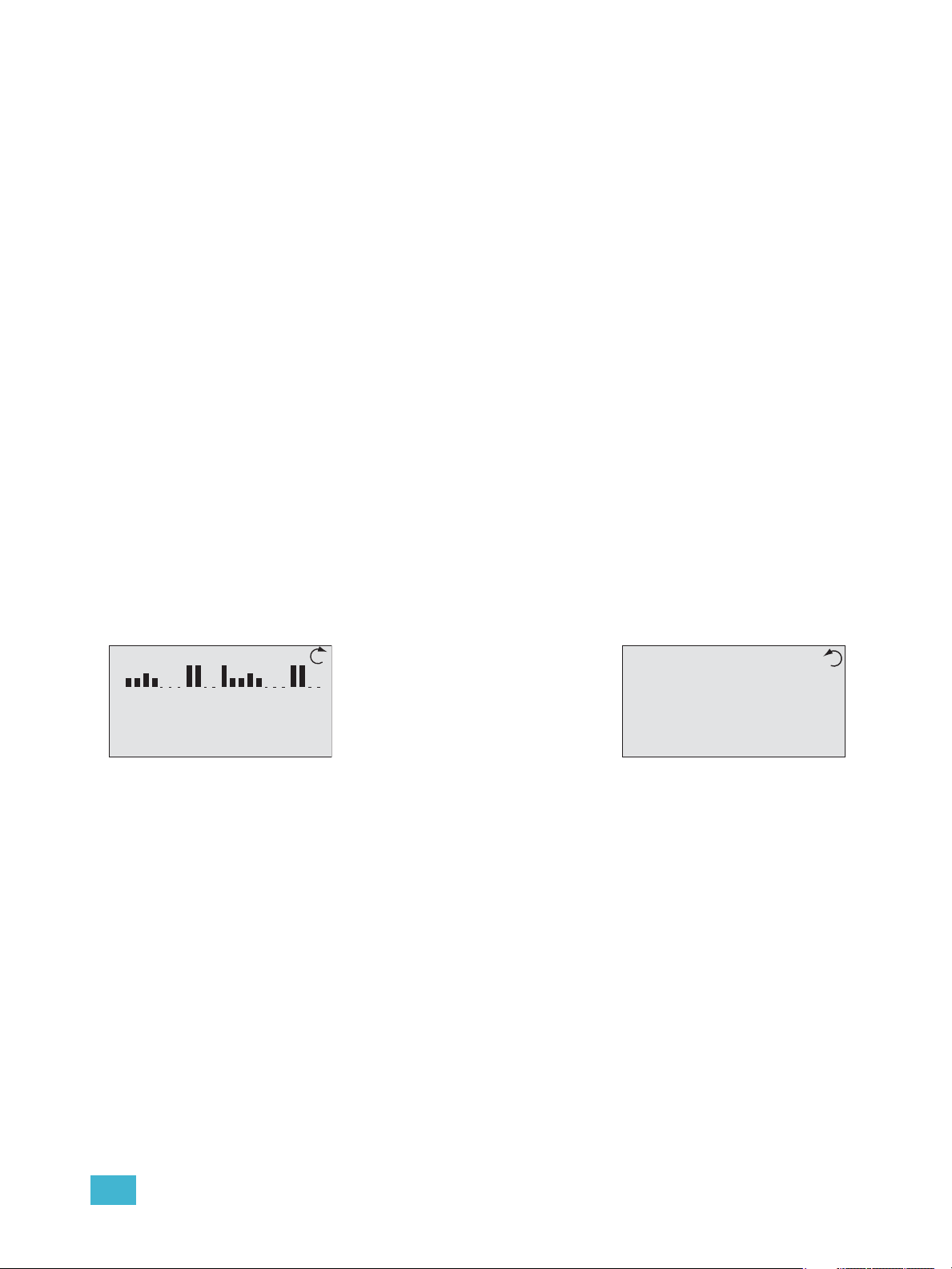
Dimming Rack Status
System OK
DMX Start = 1
Ø1: 119 Ø2: 119 Ø3: 120
60Hz 102F v1.0.2
Arch Control Status
Processor Name
IP: 10.101.10.101
System OK
DMX A: In Inactive
DMX B: Out Active
DRd12 v1.4.5
• Clockwise rotation on the touch
wheel changes the status display
to Arch Control Status.
• Counter-clockwise rotation on the
touch wheel changes the status
display back to Dimming Rack
Status.
11 Paradigm Architectural Control Processor Configuration Manual
User Interface Overview
The Paradigm ACP features a dynamic user interface with a touch wheel for easy menu
navigation, an alpha-numeric button pad for direct selection, and a bright, easy to read
graphic LCD. Additionally, an SD media card slot, integrated USB port for flash drive, and
an Ethernet port for PC connection to LightDesigner for configuration transfers are
provided.
LCD Display
The Paradigm ACP features a backlit LCD capable of displaying 8 rows of text with 21
characters per line. The first row is reserved for the menu title. The last character of rows
two through eight are reserved to display a proportional scroll bar. The scroll bar is visible
only when the menu list requires scrolling to see the entire menu.
Wake
The menu system and LCD backlight are set, by default, to sleep after one minute of
inactivity. Any button press wakes the user interface and LCD backlight. The inactivity time
setting is user selectable from the “Arch Setup” menu. See “Inactivity Time” on page 46.
Settings include 30 secs, 1 min, 5 mins, 15 min, and never.
Touch Wheel
Scroll the menu by moving your forefinger lightly around the touch wheel to highlight a
menu item. You may move your finger clockwise to scroll down the menu list or counter-
clockwise to scroll up the menu list.
The top and bottom areas of the touch wheel function as buttons for increment and
decrement operations. When navigating through a menu list, you may use these areas to
move up or down the list one menu item at a time. This may also be used to increment or
decrement numerical or selection based edits in certain menus.
1 About
2 Dimming Setup
3 Arch Setup
4 Dimming Control
5 Arch Control
6 File Operations
7 View/Clear Errors
8 Restricted Access
9 Timed Event Setup
Main Menu
scroll bar
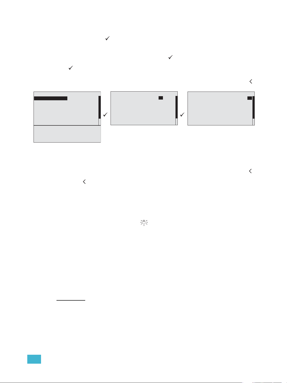
1 Installation and User Interface Overview 12
Enter
The enter button ( ) is used to commit an edit or an action such as to make a selection
from the menu list or to commit a selected value.
When focus is on the first text value (“From Dimmer:” in the example below) and an edit or
change to the selection is desired, press enter ( ). The focus changes to the next
selectable value in the display (dimmer “1” in this example). Make the edit and press enter
( ) again to change focus to the next selectable value for edit (dimmer “12” in this
example).
When all selections and edits have been made for the display, press the back button ( )
to return to the previous menu.
To advance through the list of setup options, use the touch wheel to scroll.
Back
To cancel an entry or selection and return to the previous menu, press the back button ( ).
When selection focus is on a specific value and you cancel the edit by pressing the back
button ( ), focus changes to the previous selectable value.
Multiple presses of the back button will eventually take you to the status display, either the
Dimming Rack Status (DRd only) display or the Arch Control Status display, whichever was
viewed last.
Control Menu Shortcut
The control menu shortcut button ( ) provides easy access to the dimming and
architectural control menus.
Press the control menu shortcut button once to access the dimming control menu. Press it
again to access the arch control menu. When the Paradigm ACP is installed in an host ERn
rack, only the architectural control menu is available for viewing.
Alpha-Numeric Button Pad
The numbers on the button pad may be used to select specific menu items when using
#nav shortcuts is enabled, or to enter a specific value such as a dimmer number, intensity
value, etc., while in a selectable menu. Additionally, the button pad may be used to alpha-
numerically search the menu. When a “abc” graphic is displayed in the right corner of the
display, alpha-numeric searching may be used.
Recent/And
The [recent / and] button is a dual function button.
• Used as a menu navigation shortcut, pressing [recent/] at any point in navigation
displays a list of the last seven device menus that have been accessed, with the most
recent first in the list. Selecting any of the listed items automatically directs you to that
menu. Recent command navigation relies on the current user access level to display
only accessible options.
Dimmer Setup
From Dimmer: 1 to: 12
Module Type: D20
Mode: Normal
Curve: Mod Square
Threshold: 1%
Voltage Reg: On
Max Scale: 118V
Min Scale: 6V
Dyn Preheat: Off
Transformer mode: On
DMX Res: Lo 8 bit
Dimmer Setup
From Dimmer: 1 to:12
Module Type: D20
Mode: Normal
Curve: Mod Square
Threshold: 1%
Voltage Reg: On
Max Scale: 118V
Dimmer Setup
From Dimmer: 1 to:12
Module Type: D20
Mode: Normal
Curve: Mod Square
Threshold: 1%
Voltage Reg: On
Max Scale: 118V
13 Paradigm Architectural Control Processor Configuration Manual
• Alternatively, while navigating certain menu items such as “Dimming Setup” or
“Dimming Control” menus and selecting specific dimmers, use the [/and] button to
select dimmers out of sequence. For example, [1] [/ and] [5] [/ and] [8] ( ), selects
dimmers 1, 5, and 8. Once selected you may use the numeric button pad to add a value
to the selected dimmers or use the touch wheel to scroll to a desired value.
#Nav/Thru
The [#nav / thru] button is a dual function button.
• Pressing the [#nav /] button toggles the appearance of numbers to the left of menu
items. When numbers are visible, pressing a number selects and enters into the
corresponding menu item. This is called number navigation (#nav).
• Pressing the #nav button starts a number navigation command. Most number
navigations use only two numbers (e.g. [#nav] [1] [3] for “Version Info”). The #nav
button must be pressed first to initiate each shortcut (when the numbers are not
already visible). If an incomplete command leaves the numbers visible until the
inactivity timeout occurs, the #nav command is cancelled. See “Inactivity Time” on
page 46.
• Alternatively, press the [/ thru] button while in certain menu items such as “Dimming
Setup” or “Dimming Control” menus to select a range of dimmers. For example, [1] [/
thru] [1][0] ( ), selects dimmers 1 through 10. Once selected you may use the
numeric button pad to add a value to the selected dimmers or use the touch wheel to
scroll to a desired value.
Alpha Search
Most menu items listing architectural objects in the configuration support alpha-numeric
searching. This function is similar to that found in a cellular phone contact list. Menu items
that support alpha-search provide an “abc” icon on the right side of the display title.
This icon is displayed until alpha-numeric characters are entered or the display is exited.
Any entered alpha characters appear to the right of the display title, replacing the icon. Most
menu lists that support alpha search are already alphabetized, only a small selection are
excluded from this standard. Those menu lists that are excluded only display the first
(closest to the top of the list) match.
1 About
2 Dimming Setup
3 Arch Setup
4 Dimming Control
5 Arch Control
6 File Operations
7 View/Clear Errors
8 Restricted Access
9 Timed Event Setup
Main Menu
About
Dimming Setup
Arch Setup
Dimming Control
Arch Control
File Operations
View/Cle ar Errors
Restricted Access
Timed Event Setup
Main Menu
Arch Control
Presets
Control Channels
Groups
Walls
Sequences
Macros
Overrides
Clear Arch Output
Select Space
<All>
Atrium
Hall
Section 1
Section 2
Section 3
Section 4
abc
1 Installation and User Interface Overview 14
Removable Media
USB Port
The Paradigm ACP includes a USB port for use with a flash drive, located on the front
panel. The USB flash drive is not included and can be purchased separately. A USB flash
drive can be used to store and load backup files of your architectural and dimming
configurations.
SD Media
The Paradigm ACP includes a Secure Digital (SD) media card slot located on the front
panel. The SD media card is not included and can be purchased separately. Use a
compatible SD card to store and load backup files of your architectural and dimming
configurations.
To insert a compatible SD card into the ACP SD card slot -
The SD card is small and rectangular in shape with a notched corner on the front right side.
Gently press the card into the slot, face side up with the notch on the right, until you hear
an audible click and the card end is flush with the front panel of the Paradigm ACP.
Reference the “File Operations Menu” for instructions to save or load configuration files.
To remove a compatible SD card from the ACP SD card slot -
Once the save or upload process is completed, gently press the end of the card until you
hear an audible click and the card releases from the slot.
Format the SD media card
Most SD media is pre-formatted with the correct file system. When needed you can format
the SD card yourself using a PC with Windows
®
operating system or an Apple
®
Macintosh
®
computer with a SD card reader. Reference the related operating system help for
instructions to format a SD media card.
Ethernet
Directly connect your PC with LightDesigner installed to the Ethernet port located on the
front panel of the Paradigm ACP for configuration file upload or download, firmware
updates, and live control features.
CAUTION:
2GB SD cards may utilize several different file storage systems. Some of these
systems are not compatible with the Paradigm ACP. It is recommended that 2GB
SD cards not be used with the Paradigm ACP.
The following related memory card types are incompatible with the Paradigm
ACP, even if they fit the form factor of the SD card slot:
• Multimedia Memory (MMC) card
• miniSD card
• MicroSD card with or without adaptor
• Transflash card with adaptor

15 Paradigm Architectural Control Processor Configuration Manual
Reset Switch
Reset the Paradigm ACP software and hardware by pressing the reset switch located on
the front panel of the unit. Access the reset switch using the tip of a ball point pen, or other
pointed object.
If the Paradigm ACP is hosted by a DRd enclosure, during a powered reset the dimming
engine holds the levels for the last played preset or event until the ACP has rebooted.
reset switch

2 Paradigm ACP Basic Navigation 16
Chapter 2
Paradigm ACP Basic Navigation
This chapter contains the following sections:
• Status Display . . . . . . . . . . . . . . . . . . . . . . . . . . . . . . . . . . . . .17
• Status / Error Messages . . . . . . . . . . . . . . . . . . . . . . . . . . . . .19
• Menu Navigation . . . . . . . . . . . . . . . . . . . . . . . . . . . . . . . . . . .22

17 Paradigm Architectural Control Processor Configuration Manual
Status Display
The Paradigm Architectural Control Processor (P-ACP) provides all of the basic rack and
system information on the status display. When the Paradigm ACP is installed in a DRd
enclosure, the dimming rack status display is the default status display. The architectural
control status display is the only status display available when the Paradigm ACP is
installed in an ERn enclosure.
DRd Dimming Rack Status Display
• display title - A menu’s title appears in the first row of every display for easy navigation.
• scroll to next display - When the clockwise symbol appears in the display, use the
touch wheel to scroll clockwise to the Arch Control Status display. When the counter-
clockwise symbol appears, use the touch wheel to scroll counter-clockwise for the
previous display.
• rack dimmer levels - A DRd enclosure with 1 to 24 channels will display all dimmers
with proportional levels on the line beneath the display title (as pictured above). Cross-
bussed DRd enclosure display dimmers 1-24 on the top line beneath the display title
and dimmers 25-48 on the next line.
• status message area - Status messages are common to both the Dimming Rack
Status and Arch Control Status displays. When a system error is detected, the
message changes to reflect the specific error type. When multiple errors are detected,
each error message cycles, in increasing numerical order (i.e. Dimmer 1 error, Dimmer
2 error, etc.) on the display for 1 second each. Reference “Status / Error Messages” on
page 19 for a complete listing of possible errors and the actions required to clear them.
• DMX start address - Indicates the DMX start address of the first circuit in the DRd
enclosure. An equal sign (=) before the address number indicates a 1 to 1 patch of DMX
address to the dimmers in the rack. An approximate equal sign
≈ before the address
number indicates advanced patching. The DMX value is appended with (bal) when the
rack is configured for 3 phase or 1/bi-phase balanced. Reference the “Dimming Setup
Menu” on page 30 for details on patching.
• per phase voltage - Each phase of power is measured and represented on the
Dimming Rack status display. When the rack is configured for bi-phase, only phases 1
and 2 are shown, when the rack is configured for single phase, only the single phase
data is available.
• operating frequency - The operating frequency is measured and represented on the
dimming rack status display.
Note:
Voltage displayed is a user convenience and is approximate. It is not as accurate
as using proper voltage measurement equipment.
Dimming Rack Status
System OK
DMX Start = 1
Ø1: 119 Ø2: 119 Ø3: 120
60Hz 102F v1.0.2

2 Paradigm ACP Basic Navigation 18
• internal operating temperature - The internal operating temperature is measured and
displays on the dimming rack status display. By default, temperature is displayed in °F
when the rack is 120, 240, or 277 VAC, and in °C when the rack is 230 VAC.
• rack software version - The rack software is specific to the dimming engine and may
differ from the ACP software version.
Arch Control Status Display
display title - A menu’s title appears in the first row of every display for easy navigation.
scroll to previous display - When the counter-clockwise symbol appears in the display
use the touch wheel to scroll counter-clockwise for the Dimming Rack Status display.
processor name - Prior to using configuration data with a Paradigm processor in a multi-
processor system, each processor must be configured as one of the 20 possible per
system. See “Set Processor Identity and IP Address” on page 9.
processor IP address - In addition to assigning a processor name (id) the processor IP
address must also be assigned. Automatic IP address settings are used when the
processor name (identity) is unknown.
status message area - Status messages are common to both the dimming rack and ACP
status displays. When a system error is detected, the message changes to reflect the
specific error type. When multiple errors are detected, each error message cycles on the
display, first by severity and then by chronological occurrence. Reference “Status / Error
Messages” for a complete listing of possible errors and the actions required to clear them.
DMX A: Indicates DMX port configuration and activity.
DMX B: Indicates DMX port configuration and activity. When the Paradigm ACP is installed
in a host DRd enclosure, port B must be configured as an output and is always active.
rack type - Displays the host rack type. The Paradigm ACP automatically detects the rack
type as either an ERn, DRd6, DRd12, or DRd12AX12X.
software version - The ACP software is specific to the Paradigm Architectural Control
Processor and may differ in version number from the dimming engine software version.
Arch Control Status
Processor Name
IP: 10.101.10.101
System OK
DMX A: In Inactive
DMX B: Out Active
DRd12 v1.4.5

19 Paradigm Architectural Control Processor Configuration Manual
Status / Error Messages
Status messages display on both the dimming rack status display and the Arch Control
Status display. When the Paradigm ACP is installed in a DRd enclosure, use the touch
wheel to scroll clockwise ( ) to view the Arch Control Status display.
Status messages provide you with system wide, rack specific or even just dimmer specific
information including errors. Important errors may suppress display of other existing errors
on the status display. For a complete list of errors see “Status / Error Messages Generated
by the Paradigm ACP” and “Status / Errors Messages Generated by the DRd Dimming
Engine” .

2 Paradigm ACP Basic Navigation 20
Status / Error Messages Generated by the Paradigm ACP
Message Displayed Description Action
System OK No errors exist No action required for normal operation.
Emergency Active Panic/Emergency bypass
operation is active
Occurs only when the Paradigm ACP is
installed in a host DRd enclosure. The
programmed Emergency bypass look is
played. If load shedding is set to “On” all
loads not in emergency are shed. Also the
dimming setup, restore defaults, load
dimming configuration, and update
firmware menus will be locked out from
user intervention.
Dimming Firmware /
Mismatch Detected
Firmware version
mismatch between the
DRd enclosure and the
Paradigm ACP.
Occurs only when the Paradigm ACP is
installed in a host DRd enclosure. This is
resolved through a firmware update
procedure. See “Update Firmware” on
page 62.
Dimming Engine
Communication Failure!
The Paradigm ACP cannot
communicate with the DRd
dimming engine properly.
Occurs only when the Paradigm ACP is
installed in a host DRd enclosure. The
error is clearable by correcting the failure
point.
ACP and DRd
Configuration Mismatch
Occurs when the dimming
configuration stored locally
on the Paradigm ACP does
not match the configuration
running within the DRd
dimming engine.
Occurs only when the Paradigm ACP is
installed in a host DRd enclosure. The
menu locks out additional navigation and
requires you to confirm use of either the
dimming rack configuration or use of the
dimming configuration as stored on the
Paradigm ACP. Alternatively you can
select “Quick Rack Setup” to create a new
configuration.
AX12X ACP Position
Error
An error display warns you
when the Paradigm ACP is
installed in “Rack 2” of a
cross-bussed application.
Occurs only when the Paradigm ACP is
installed in a cross-bussed host DRd
enclosure. This error cannot be cleared
except by correctly installing the AX12X
interconnect cable or by moving the
Paradigm ACP to the enclosure with the
interconnect cable end labeled “rack 1”.
Version Mismatch: LightDesigner version used
to create/edit the arch
configuration is a different
version than the Paradigm
ACP software.
Either update the configuration version
via LightDesigner software or downgrade
the Paradigm ACP software version to
resolve this mismatch.
Unassigned Processor
Please Assign
Processor / IP settings
Each processor must be
configured as one of the 20
possible per system.
Assign processor identity from the face
panel UI by the processor’s name (e.g.
“Processor 1”, “1st Floor West”, etc.).
Internal Clock Error /
Low Battery
An error displays during
processor boot, indicating
the real timeclock backup
battery is low.
Contact ETC Technical Services.

21 Paradigm Architectural Control Processor Configuration Manual
Status / Errors Messages Generated by the DRd Dimming Engine
Message Displayed Description Action
Rack Error / Rack
Overtemp
Ambient temperature is
above rated temperature
range.
All dimmers in the enclosure are disabled
from use until the ambient temperature is
within an acceptable operating range.
Rack Warning / High
Operating Temp
Ambient temperature is
approaching maximum
temperature.
Correct the ambient temperature to within
specification.
Rack Warning / Low
Operating Temp
Ambient temperature is
below rated temperature
range.
Correct the ambient temperature to within
specification.
Rack Error/Freq out of
Range
Input power frequency is
out of operating range.
All dimmers in the enclosure are disabled
from use until the input power frequency is
within acceptable operating range.
Dimmer Overtemp/
Dimmers ## and ##
Dimmer is in an overtemp
condition.
The specified dimmer automatically
disables. Verify loads are within
acceptable limits. Try swapping dimmer
modules to isolate if the problem is within
a module.
Rack Error/Phase 1
Missing
Phase A is off. Check mains power feed.
Rack Error/Phase 2
Missing
Phase B is off. Check mains power feed.
Rack Error/Phase 3
Missing
Phase C is off. Check mains power feed.
Rack Error/Phase 1
Over voltage
Phase A voltage is above
rated voltage range.
All dimmers in the enclosure are disabled
from use until Phase A voltage is within
acceptable operating range.
Rack Error/Phase 2
Over voltage
Phase B voltage is above
rated voltage range.
All dimmers in the enclosure are disabled
from use until Phase B voltage is within
acceptable operating range.
Rack Error/Phase 3
Over voltage
Phase C voltage is above
rated voltage range.
All dimmers in the enclosure are disabled
from use until Phase C voltage is within
acceptable operating range
Rack Error/Phase 1
Under voltage
Phase A voltage is below
rated voltage range.
Correct input voltage to acceptable range.
Rack Error/Phase 2
Under voltage
Phase B voltage is below
rated voltage range.
Correct input voltage to acceptable range.
Rack Error/Phase 3
Under voltage
Phase C voltage is below
rated voltage range.
Correct input voltage to acceptable range.
Rack Error/Fan Error or
Failure
Fan is not operating
properly.
Verify that the fan is not obstructed.

2 Paradigm ACP Basic Navigation 22
Menu Navigation
The Paradigm ACP menu is designed with consistent navigation from the user interface
either using the numeric button pad or the touch wheel.
The main menu is the root for all menu navigation. When a menu item is selected from the
main menu, a secondary menu displays including multiple functions for selection.
When a menu item is selected, an operation menu displays for your action or edit of objects.
Operations for your action and/or edit use descriptive text which is followed by a colon “:”
and a value.
The numeric button pad or the touch wheel may be used to edit specific objects from the
operation menu, such as dimmer number, levels, etc. Once an edit has been made, press
the enter ( ) button to accept the selection.
Use the touch wheel to navigate to the next object for action or edit. To return to the
previous operation, press the back ( ) button. Continue pressing the back ( ) button to
return to the menu list and eventually the main menu.
The back ( ) button may also be used with any “Yes” or “No” dialog box. Pressing the back
( ) button is similar to selecting “No”.
Note:
To navigate the menu using the numeric button pad, press the #nav/thru button
on the button pad. This enables number navigation and displays the specified
numbers to the left of an existing menu list. See “#Nav/Thru” on page 13.

23 Paradigm Architectural Control Processor Configuration Manual
Chapter 3
Programming
This chapter contains the following sections:
• About Menu . . . . . . . . . . . . . . . . . . . . . . . . . . . . . . . . . . . . . . .24
• Dimming Setup Menu . . . . . . . . . . . . . . . . . . . . . . . . . . . . . . .30
• Arch Setup Menu . . . . . . . . . . . . . . . . . . . . . . . . . . . . . . . . . . .41
• Dimming Control Menu . . . . . . . . . . . . . . . . . . . . . . . . . . . . . .49
• Arch Control Menu. . . . . . . . . . . . . . . . . . . . . . . . . . . . . . . . . .51
• File Operations Menu . . . . . . . . . . . . . . . . . . . . . . . . . . . . . . .56
• View/Clear Errors Menu. . . . . . . . . . . . . . . . . . . . . . . . . . . . . .64
• Restricted Access Menu . . . . . . . . . . . . . . . . . . . . . . . . . . . . .66
• Timed Event Setup Menu . . . . . . . . . . . . . . . . . . . . . . . . . . . .68

3 Programming 24
About Menu
When there is no architectural configuration file loaded into the Paradigm ACP, certain
menu lists are not available for viewing or use. For instance, without an architectural
configuration file there will be no DMX level data, project information, or system network
information to view.
About Dimmer
Use the touch wheel to scroll to a different dimmer or use the alpha-numeric button pad to
specify a dimmer number. Dimmer data updates when a new dimmer is selected. Push
enter ( ) to view additional details about your selected dimmer.
To exit the “About Dimmer menu and return to the previous menu press the back
button ( ).
DMX Level Data
When a streaming sACN (sACN) patch exists for local DMX ports, additional patch
information is displayed beneath each port. For DMX inputs this patch information pertains
to sACN output, and for DMX outputs this patch information pertains to sACN input.
• When a streaming sACN patch is shown as “Universe/1st used address”. This indicates
a 1-to-1 patch between the DMX port and the sACN universe for all 512 addresses.
•The "" character is shown when a port has a sACN patch but is not a 1-to-1 patch. In
this instance, the first sACN universe /address used for that port is listed for the lowest
address of that sACN universe.
Note:
The “About Menu” is provided for you to view information only. There are no
editing tools or menu lists available.
1 About Dimmer
2 DMX Level Data
3 Version Info
4 Project Information
5 Statistics
6 View Message Log
7 System Network
About
8 Stations & LonWorks
The “About Menu” provides you direct access to view
details about your dimmers (when the Paradigm ACP is
installed in a host DRd rack), current DMX level data,
software version information, project information,
statistics, message log, system network, and stations
and LonWorks.
About Dimmer 1
DMX Channel: 125
Module Type: D20F
Mode: Fluorescent
Current Level: 100%
Source: DMX Input
<push Enter for more>
The “About Dimmer” menu displays only when the Paradigm
ACP is installed in a host DRd rack. By default, the “About
Dimmer” menu automatically selects and displays the data for
the first dimmer in the rack. Notice the title bar displays the
selected dimmer number.
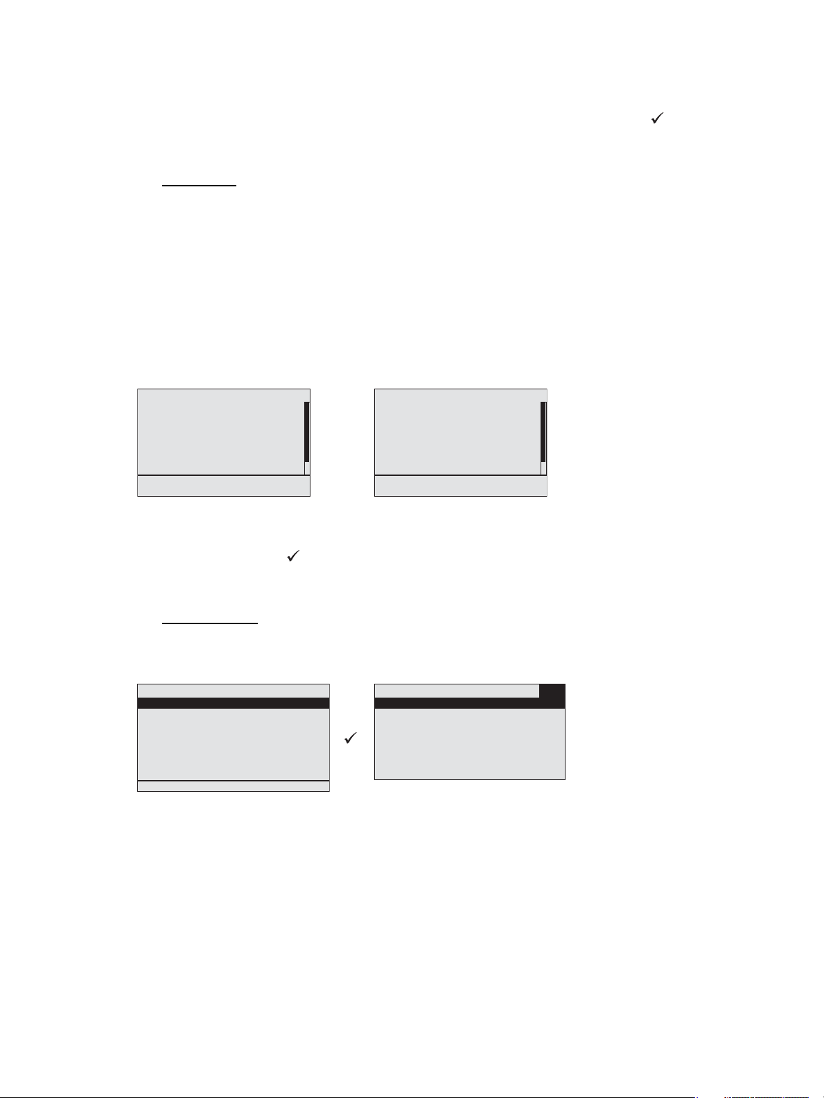
DMX Level Data
Port A: Input
1/1 Active
Port B: Output
≈2/1 Active
The “About DMX Level Data” menu displays the available DMX
input and DMX output port and its current status of active,
inactive, or disabled. Status is updated once every 500ms.
When a DMX port is disabled, there is no data to display. DMX
output ports are only inactive when there are no patched
addresses.

25 Paradigm Architectural Control Processor Configuration Manual
DMX Input
Selecting the active input port displays DMX data sorted
by the input address. The next column displays the level
information for the addresses in the far left column.
When there is no active DMX input, the input level
column displays “---”. Levels are displayed in values 0 -
100. The current DMX level updates about every 250ms.
The next column displays any related local DMX output
that has been patched and lists port A or port B and its level information. When there is not
a relationship or patch for a given input address, “---” displays for level and any applicable
output address data.
The last column of information displays “A” or “N” or “AN”. The “A” indicates the DMX
address is patched to an architectural control, which may also be recorded into presets. The
“N” indicates that DMX address is patched to one or more network sACN outputs and is
providing sACN control from DMX.
Use the touch wheel to scroll through all channels in the list or use the alpha-numeric button
pad to specify a channel. To exit the About DMX Level Data menu and return to the
previous menu press the back button ( ).
DMX Output
Selecting the active output port displays DMX data
sorted by the output addresses in the far left column. The
next column displays the level information for the
address. When there is no active DMX output, the output
level column displays “---”. Levels are displayed in
values 0 - 100.
The current DMX level updates about every 250ms.
The next column displays any related local DMX input which has been patched and lists
port A or port B and its level information. When there is not a relationship or patch for a
given output address, “---” displays for level and any applicable input address data.
The last column of information displays “A” or “N” or “AN”. The “A” indicates the DMX
address is patched to an architectural control, which also affects level information. The “N”
indicates that DMX address is patched to an external sACN control.
DMX level data displays only when there is an active DMX input to the system. When no
DMX input is active “---” is displayed in the level column to indicate no level information is
available.
Use the touch wheel to scroll through all addresses in the list or use the alpha-numeric
button pad to specify an address. To exit the About DMX Level Data menu and return to
the previous menu press the back button ( ).
A: Input DMX Data
In Lvl Out Lvl
127 --- B:127 100 AN
128 50 B:128 100 A
129 50 B:192 50 N
130 0 B:--- --- AN
131 --- B:--- ---
132 99 B:512 99
Out Lvl In Lvl
127 100 A:127 100 AN
128 50 A:128 100 A
129 50 A:192 50 N
130 0 A:--- --- AN
131 15 A:--- ---
132 99 A:512 99
B: Output DMX Data
Loading...