


 Loading...
ETC Setup Guide
Response Mk2 DIN Rail Gateway
This guide covers installation and basic setup of the Response Mk2 DIN Rail Gateway. You can configure additional software features using ETC Concert software. Reference the Help system built into Concert for more information. ETC Concert software can be found at etcconnect.com/Concert.
Overview
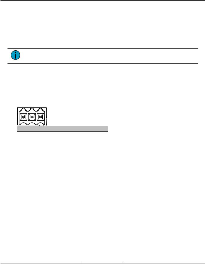
The DIN rail gateway comes with one, two, or four ports.
DC power |
Ethernet |
|
|
|
connection |
|
|
|
|
input |
|
|
|
|
|
|
|
|
|
|
OLED screen |
Up, Down, Back, |
||
|
Enter buttons |
|||
|
|
|||
|
|
|
|
|
Reset button |
DMX termination switches |
|
Three-pin terminals (Typical 1, 2, or 4)
Action Buttons
•Up, Down, Back buttons - The Back button allows you to return to the previous menu or option and the Up and Down buttons navigate between menu options
•Enter - The Enter button allows you to advance to the next available menu option or commit a modified selection
•Reset - The Reset button provides a physical button to reset the gateway
LED Indicators
•Power - Solid blue indicates that power is supplied
•Network - Solid green indicates network connection and blinking indicates network activity
Corporate Headquarters Middleton, WI, USA +1 608 831 4116 London, UK +44 (0)20 8896 1000
Holzkirchen, DE +49 (80 24) 47 00-0 Rome, IT +39 (06) 32 111 683 Hong Kong +852 2799 1220 Paris, FR +33 1 4243 3535 Web etcconnect.com Support support.etcconnect.com Contact etcconnect.com/contactETC
© 2020 Electronic Theatre Controls, Inc. Trademark and patent info: etcconnect.com/ip
Product information and specifications subject to change. ETC intends this document to be provided in its entirety. 4268M2230 Rev C Released 2020-08
ETC Setup Guide
DIN Rail Gateway
Electrical Specifications
The gateways are powered by either auxiliary power or Power over Ethernet (PoE).
•Auxiliary power input rated voltage of 12-24 VDC, 6.49 W Max
•10/100Base-T, PoE power Class 2 (IEEE 802.3af)
For auxiliary power, the DIN rail gateway uses a three-position screw clamp terminal block.
If you supply both PoE and auxiliary power, the gateway defaults to using auxiliary. If auxiliary power is lost, the gateway will reboot and then begin using PoE.
Note: If you are using an external power supply, it must be rated at a maximum of 15 watts.
DMX Connection
The Response Mk2 Gateways send and receive DMX-512 control signals. DMX cables must be acceptable for DMX data transmission and connections should follow the standard pinouts per the chart below.
The DIN rail gateway comes with one, two, or four terminal connectors.
Pinout
1 |
3 |
DMX-512 Pinouts for Terminal Header
Pin |
Use |
Typical Wire Color |
1 |
Common (shield) |
clear/shield |
2 |
Data - |
black |
3 |
Data + |
red |
DIN Rail Gateway |
Page 2 of 8 |
ETC |

ETC Setup Guide
DIN Rail Gateway
Wiring the Terminal Connector
The terminal header can accept two types of connectors (both connector types are provided with the gateway):
•DMX Cable (three-position screw connector used with Belden 9729 or equivalent cable)
•DMX Cat5 (three-position Cat5 insulation displacement connector used with Cat5 or equivalent cable)
DMX Cable Preparation and Termination
Note: Not for use with Cat5, Cat5e, or Cat6 cable. When running DMX with these cable types, use the provided 3-position IDC connector and reference DMX Cat5 Preparation and Termination on the next page.
This instruction assumes preparation of Belden 9729 (or equivalent) cable for termination to the three-position screw terminal connector provided.
1.Install the cable so there is an 20 cm (8 in) service loop available at the rear of the gateway.
2.Strip 18 cm (7 in) off the outer jacket.
3.Label the cable with the data type and run designation. (DMX1, DMX2, etc.)
4.Strip the foil shielding from each wire set to within 6 mm (1/4 in) of the outer jacket.
5.Untwist the shield wire from each pair and apply a piece of 1.6 mm (1/16 in) clear heat shrink to each shield wire.
6.Twist each shield wire back onto its data pair, and then apply a 4 cm (1.5 in) piece of 0.5 cm (3/16 in) heat shrink all the way down each 3-wire set. Make sure to capture the foil shielding at the base.
7.Apply the 5 cm (2 in) piece of the 1 cm (3/8 in) heat shrink, centered on the end of the cable jacket and the bases of all the wires in the cable.
8.Cap the ends of the unused pair of wires with a 2.5 cm (1 in) piece of 0.5 cm (3/16 in) heat shrink centered over the end of the wires.
9.Strip 6 mm (1/4 in) of insulation from all of the wires to be used.
10.Maintain the wire pair twist as close to the screw terminal connector as possible and terminate the wires.
3
D1
8
7
12
5
6 |
11 |
5
12
10
COM - +
a.Insert the common (shield) wire into the 


 terminal labeled “DMX " and secure.


b.Insert the data - wire (typically black) into the terminal labeled “DMX -” and secure.
c.Insert the data + wire (typically red or white) into the terminal labeled “DMX +” and secure.
11.Bend back the unused set of wires and secure them to the cable with a wire tie.
12.Secure the terminated wire sets together with a wire tie 5 cm (2 in) from the connector.
DIN Rail Gateway |
Page 3 of 8 |
ETC |
Loading...