


 Loading...


 ®
®
CEM3
User Manual
Version 1.5.1
Copyright © 2014 Electronic Theatre Controls, Inc .
All Rights reserved .
Product information and specifications subject to change .
Part Number: 7140M1200-1.5.1 Rev A
Released : 2014 - 06
ET C ® an d Sensor® are either registered trademarks or trademarks of Electronic Theatre Controls, Inc . in the United States and other countries .
All other trademarks, both marked and not marked, are the property of their respective owners .
ETC intends this document, whether printed or electronic, to be provided in its entirety .

T a b l e o f C o n t e n t s
|
|
|
Introduction . . . . . . . . . . . . . . . . . . . . . . . . . |
. 1 |
|
|
|
Using this Manual. . . . . . . . . . . . . . . . . . . . . . . . . . . . . . . . . . . . . . . |
.2 |
|
|
|
Text Conventions. . . . . . . . . . . . . . . . . . . . . . . . . . . . . . . . . . . . |
.2 |
|
|
|
Help from ETC Technical Services . . . . . . . . . . . . . . . . . . . . . . . . . |
.3 |
C h a p t e r |
1 |
Getting Started . . . . . . . . . . . . . . . . . . . . . . . |
5 |
|
|
|
|
The User Interface . . . . . . . . . . . . . . . . . . . . . . . . . . . . . . . . . . . . . . |
.6 |
|
|
|
CEM3 face panel . . . . . . . . . . . . . . . . . . . . . . . . . . . . . . . . . . . . |
.6 |
|
|
|
Navigation . . . . . . . . . . . . . . . . . . . . . . . . . . . . . . . . . . . . . . . . . |
.6 |
|
|
|
Performing a Quick Setup . . . . . . . . . . . . . . . . . . . . . . . . . . . . . . . . |
.7 |
|
|
|
Other Setup Functions. . . . . . . . . . . . . . . . . . . . . . . . . . . . . . . . |
.8 |
C h a p t e r |
2 |
System Reference . . . . . . . . . . . . . . . . . . . . |
9 |
|
|
|
|
Important Concepts . . . . . . . . . . . . . . . . . . . . . . . . . . . . . . . . . . . . . |
10 |
|
|
|
Advanced Features (AF) . . . . . . . . . . . . . . . . . . . . . . . . . . . . . . |
10 |
|
|
|
Balanced (rack numbering) . . . . . . . . . . . . . . . . . . . . . . . . . . . . |
10 |
|
|
|
Circuit. . . . . . . . . . . . . . . . . . . . . . . . . . . . . . . . . . . . . . . . . . . . . |
11 |
|
|
|
Configuration . . . . . . . . . . . . . . . . . . . . . . . . . . . . . . . . . . . . . . . |
11 |
|
|
|
Dimmer Doubling (UL/ 120V 60 Hz systems only) . . . . . . . . . . |
11 |
|
|
|
Latch-Lock . . . . . . . . . . . . . . . . . . . . . . . . . . . . . . . . . . . . . . . . . |
12 |
|
|
|
Lug. . . . . . . . . . . . . . . . . . . . . . . . . . . . . . . . . . . . . . . . . . . . . . . |
12 |
|
|
|
Panic . . . . . . . . . . . . . . . . . . . . . . . . . . . . . . . . . . . . . . . . . . . . . |
12 |
|
|
|
Patch . . . . . . . . . . . . . . . . . . . . . . . . . . . . . . . . . . . . . . . . . . . . . |
13 |
|
|
|
Preset Functions . . . . . . . . . . . . . . . . . . . . . . . . . . . . . . . . . . . . |
13 |
|
|
|
Redundant Tracking (ESR and FDX racks only) . . . . . . . . . . . . |
15 |
|
|
|
Straight (rack numbering) . . . . . . . . . . . . . . . . . . . . . . . . . . . . . |
16 |
|
|
|
Menu Structure. . . . . . . . . . . . . . . . . . . . . . . . . . . . . . . . . . . . . . . . . |
17 |
|
|
|
Test . . . . . . . . . . . . . . . . . . . . . . . . . . . . . . . . . . . . . . . . . . . . . . |
17 |
|
|
|
About . . . . . . . . . . . . . . . . . . . . . . . . . . . . . . . . . . . . . . . . . . . . . |
17 |
|
|
|
Setup . . . . . . . . . . . . . . . . . . . . . . . . . . . . . . . . . . . . . . . . . . . . . |
18 |
|
|
|
Dimmer Property Definitions . . . . . . . . . . . . . . . . . . . . . . . . . . . . . . |
19 |
|
|
|
Rack Property Definitions. . . . . . . . . . . . . . . . . . . . . . . . . . . . . . . . . |
22 |
|
|
|
Dimmer Curves . . . . . . . . . . . . . . . . . . . . . . . . . . . . . . . . . . . . . . . . |
23 |
|
|
|
Linear. . . . . . . . . . . . . . . . . . . . . . . . . . . . . . . . . . . . . . . . . . . . . |
23 |
|
|
|
Modified Linear (Mod-Linear). . . . . . . . . . . . . . . . . . . . . . . . . . . |
25 |
|
|
|
Square Law (Square). . . . . . . . . . . . . . . . . . . . . . . . . . . . . . . . . |
25 |
|
|
|
Modified Square Law (Mod-Square) . . . . . . . . . . . . . . . . . . . . . |
26 |
|
|
|
Sensor 2.0 . . . . . . . . . . . . . . . . . . . . . . . . . . . . . . . . . . . . . . . . . |
26 |
|
|
|
Stage 1 . . . . . . . . . . . . . . . . . . . . . . . . . . . . . . . . . . . . . . . . . . . |
27 |
|
|
|
Stage 2 . . . . . . . . . . . . . . . . . . . . . . . . . . . . . . . . . . . . . . . . . . . |
27 |
|
|
|
Fluor 1 . . . . . . . . . . . . . . . . . . . . . . . . . . . . . . . . . . . . . . . . . . . . |
28 |
|
|
|
Fluor 2 . . . . . . . . . . . . . . . . . . . . . . . . . . . . . . . . . . . . . . . . . . . . |
28 |
|
|
|
Andi . . . . . . . . . . . . . . . . . . . . . . . . . . . . . . . . . . . . . . . . . . . . . . |
29 |
|
Table of Contents |
|
i |
|
|
|
|||
|
|
|
|
|
C h a p t e r 3
A p p e n d i x A A p p e n d i x B
A p p e n d i x C
VIP 90 . . . . . . . . . . . . . . . . . . . . . . . . . . . . . . . . . . . . . . . . . . . .29
Dimmer Output Diagram . . . . . . . . . . . . . . . . . . . . . . . . . . . . . . . . .30
Common Tasks. . . . . . . . . . . . . . . . . . . . . . 31
Recording and Playing Back Presets . . . . . . . . . . . . . . . . . . . . . . . .32 Preset Menu . . . . . . . . . . . . . . . . . . . . . . . . . . . . . . . . . . . . . . .32
Saving or Uploading Files and Firmware . . . . . . . . . . . . . . . . . . . . .33 Saving Configurations . . . . . . . . . . . . . . . . . . . . . . . . . . . . . . . .33 Loading Configurations . . . . . . . . . . . . . . . . . . . . . . . . . . . . . . .33 Loading CEM3 Software . . . . . . . . . . . . . . . . . . . . . . . . . . . . . .34
Setting Up Panic. . . . . . . . . . . . . . . . . . . . . . . . . . . . . . . . . . . . . . . .35
Setting Up Patch . . . . . . . . . . . . . . . . . . . . . . . . . . . . . . . . . . . . . . .37 Automatic Patch. . . . . . . . . . . . . . . . . . . . . . . . . . . . . . . . . . . . .37 Manual Patch. . . . . . . . . . . . . . . . . . . . . . . . . . . . . . . . . . . . . . .38
Set Data Loss Behavior . . . . . . . . . . . . . . . . . . . . . . . . . . . . . . . . . .38
Setting Up CEM3 on the Network . . . . . . . . . . . . . . . . . . . . . . . . . .39 Network Setup for Redundant Tracking Racks . . . . . . . . . . . . .39 Working with an FTP Server . . . . . . . . . . . . . . . . . . . . . . . . . . .39
Setting Rack DIP Switches and Termination . . . . . . . . . . . . . . . . . .40 DIPswitch settings . . . . . . . . . . . . . . . . . . . . . . . . . . . . . . . . . . .40 Termination Switches . . . . . . . . . . . . . . . . . . . . . . . . . . . . . . . .41
Rack Maintenance and Cleaning . . . . . . . . . . . . . . . . . . . . . . . . . . .42 Cleaning Rack Air Filters . . . . . . . . . . . . . . . . . . . . . . . . . . . . . .42 Vacuuming Dimmer Modules. . . . . . . . . . . . . . . . . . . . . . . . . . .43
Replacing AF Cards . . . . . . . . . . . . . . . . . . . . . . . . . . . . . . . . . . . . .44 Restore Rack Defaults . . . . . . . . . . . . . . . . . . . . . . . . . . . . . . . . . . .45
Error Messages. . . . . . . . . . . . . . . . . . . . . . 47
Using the CEM3 Web Interface . . . . . . . . . 49
System. . . . . . . . . . . . . . . . . . . . . . . . . . . . . . . . . . . . . . . . . . . .49
Dimmers . . . . . . . . . . . . . . . . . . . . . . . . . . . . . . . . . . . . . . . . . .49
Set Levels . . . . . . . . . . . . . . . . . . . . . . . . . . . . . . . . . . . . . . . . .50
Setup . . . . . . . . . . . . . . . . . . . . . . . . . . . . . . . . . . . . . . . . . . . . .50
Files . . . . . . . . . . . . . . . . . . . . . . . . . . . . . . . . . . . . . . . . . . . . . .50
Redundant Tracking Systems. . . . . . . . . . . 51
Redundant Tracking Switch. . . . . . . . . . . . . . . . . . . . . . . . . . . .51
Automatic Control . . . . . . . . . . . . . . . . . . . . . . . . . . . . . . . . . . .52
Display Status . . . . . . . . . . . . . . . . . . . . . . . . . . . . . . . . . . . . . .52
Configuration Management in Redundant Tracking Systems . .53
Firmware Upgrades in Redundant Tracking Systems . . . . . . . .53
ii |
CEM3 User Manual |

A p p e n d i x D
FDX 3000 Dimmer Racks . . . . . . . . . . . . . . 55
Hardware . . . . . . . . . . . . . . . . . . . . . . . . . . . . . . . . . . . . . . . . . .55 Regulatory Information . . . . . . . . . . . . . . . . . . . . . . . . . . . . . . .57 Initial Setup . . . . . . . . . . . . . . . . . . . . . . . . . . . . . . . . . . . . . . . .57 Module Types . . . . . . . . . . . . . . . . . . . . . . . . . . . . . . . . . . . . . .57 Advanced Features in FDX . . . . . . . . . . . . . . . . . . . . . . . . . . . .58 FDX2000 vs. FDX3000 Dimmer Curve Comparison . . . . . . . . .59
iii
iv |
CEM3 User Manual |

Introduction
Welcome to your new CEM3 Power Control system!
This manual is designed to introduce you to the CEM3 user interface and the primary features and functions available to you in the setup and use of your CEM3 power control system.
For additional information you may also access our online CEM3 wiki page at http:// www.etcconnect.com/Sensor3help.This wiki is updated regularly to reflect the most current information and may provide information on less commonly used features of your CEM3.
The introduction contains the following sections:
• Using this Manual . . . . . . . . . . . . . . . . . . . . . . . . . . . . . . . . . . .2
• Text Conventions. . . . . . . . . . . . . . . . . . . . . . . . . . . . . . . . . . . .2
• Help from ETC Technical Services. . . . . . . . . . . . . . . . . . . . . .3
|
Introduction |
1 |
|
|
|

Using this Manual
The following graphics and conventions are used throughout this manual to convey important information.
N o t e : |
Notes are helpful hints and information that is supplemental to the main text. |
|
|
|
|
C A U T I O N : |
A Caution statement indicates situations where there may be undefined or |
|
unwanted consequences of an action, potential for data loss or an equipment |
|
problem. |
|
|
|
|
W A R N I N G : |
A Warning statement indicates situations where damage may occur, people |
|
may be harmed, or there are serious or dangerous consequences of an |
|
action. |
|
|
|
|
W A R N I N G : |
RISK OF ELECTRIC SHOCK! This warning statement indicates situations |
|
where there is a risk of electric shock. |
|
|
Text Conventions
Many of the procedures in this manual use a combination of text conventions to identify various types of inputs that are used to program your CEM3. Below is a list of commonly used conventions in this manual.
Bold is used to indicate a necessary action (such as a button press or menu path) in a procedure.
[Brackets] are used to indicate the press of a tactile button on the face of the CEM3 (such as [Setup], [Test], and [Enter]).
Italics are used to indicate a menu item listed in the display window.
Right angle bracket (>) is used to indicate a flow of button presses and menu selection options.
When used together, this instruction: [Setup]>Panic>Record Panic Look>[Enter] indicates you should, “Press [Setup], select Panic from the menu, select Record Panic Look from the menu, Press [Enter].”
Advantages of Electronic Version
ETC's technical documentation is designed for printed or electronic use. However, there are many bonuses to using the electronic (.PDF) versions of our documents. Aside from having all of the benefits of a PDF (such as word find, bookmarks, and commenting tools) ETC documents include the ability to click headings in the Table of Contents or Index and jump to the desired page. Also, our cross-references (indicated in blue italics like this: Introduction, page 1) are links that may be clicked to jump to the specific part of the manual. And all of ETC's documents are available for free download from our website: www.etcconnect.com.
You can download a .PDF copy of this manual directly from the USB port on the CEM3. See
About CEM3, page 17.
Please email comments about this manual to: TechComm@etcconnect.com
2 |
CEM3 User Manual |

Help from ETC Technical Services
If you are having difficulties, your most convenient resources are the references given in this user manual. To search more widely, try the ETC Web site at www.etcconnect.com or the Sensor3 Online Community Wiki at http://www.etcconnect.com/Sensor3help.
If none of these resources is sufficient, contact ETC Technical Services directly at one of the offices identified below. Emergency service is available from all ETC offices outside of normal business hours.
When calling for help, please have the following information handy:
•Product model and serial number (located on the bottom of the CEM3)
•Dimmer manufacturer and installation type
•Other components in your system (Unison®, other consoles, etc.)
Americas |
United Kingdom |
Electronic Theatre Controls Inc. |
Electronic Theatre Controls Ltd. |
Technical Services Department |
Technical Services Department |
3031 Pleasant View Road |
26-28 Victoria Industrial Estate |
Middleton, WI 53562 |
Victoria Road, |
800-775-4382 (USA, toll-free) |
London W3 6UU England |
+1-608 831-4116 |
+44 (0)20 8896 1000 |
service@etcconnect.com |
service@etceurope.com |
Asia |
Germany |
Electronic Theatre Controls Asia, Ltd. |
Electronic Theatre Controls GmbH |
Technical Services Department |
Technical Services Department |
Room 1801, 18/F |
Ohmstrasse 3 |
Tower 1, Phase 1 Enterprise Square |
83607 Holzkirchen, Germany |
9 Sheung Yuet Road |
+49 (80 24) 47 00-0 |
Kowloon Bay, Kowloon, Hong Kong |
techserv-hoki@etcconnect.com |
+852 2799 1220 |
|
service@etcasia.com |
|
|
Introduction |
3 |
|
|
|
4 |
CEM3 User Manual |
C h a p t e r 1
Getting Started
This chapter contains the following sections:
• The User Interface . . . . . . . . . . . . . . . . . . . . . . . . . . . . . . . . . . .6
• Navigation. . . . . . . . . . . . . . . . . . . . . . . . . . . . . . . . . . . . . . . . . .6
• Performing a Quick Setup. . . . . . . . . . . . . . . . . . . . . . . . . . . . .7
|
|
|
1 |
Getting Started |
5 |
The User Interface
This section will clarify the physical features of the hardware interface and the general functionality with the software.
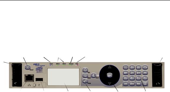
CEM3 face panel
These are the various components in the hardware interface. Familiarize yourself with these terms as they are used throughout this manual.
|
|
LEDs identify current states of: |
|
|
||
Eject - Pull |
Reset |
Power |
DMX Ports Network |
Panic |
|
Eject |
|
|
|
|
|
|
|
both levers |
|
|
|
|
|
|
forward from |
|
|
|
|
|
|
the top edge. |
|
|
|
|
|
|
Grasp and pull |
|
|
|
|
|
|
to remove |
|
|
|
|
|
|
control module |
|
|
|
|
|
|
(power down |
Net3 |
USB |
Display window |
Navigation |
Scroll |
Keypad |
the rack before |
||||||
removing). |
Ethernet |
Load Software and |
Buttons |
wheel |
|
|
|
|
configurations |
|
|
|
|
Navigation
Scroll Wheel
Use the scroll wheel and up/down arrows to move the selection cursor on any menu screen until the desired item is highlighted. You can also tap the top or bottom of the scroll wheel to move the display cursor up or down.
The scroll wheel also lets you scroll through number fields (such as circuit number) or through the available options for a selected item (such as Module Type).
The center button of the scroll wheel functions as [Enter]. Press [Enter] to select the highlighted item on the display window or to commit entered data.
Keypad
Use keypad to enter values for any value fields in the display window. When setting levels you can select individual dimmers or ranges of dimmers using the [and] and [thru] buttons.
Both the center button of the scroll wheel and the bottom right keypad button function as [Enter]. Press [Enter] to select the highlighted item on the display window or to commit entered data.
The menu buttons ([Test], [About], [Setup]) and the [Back] button are integral in navigating the menu structure.
Display Menus
The navigation buttons are used to navigate the menu structure.
Press the menu buttons ([Test], [About], [Setup]) to access features within that menu type (see Menu Structure, page 17).
Use the scroll wheel to navigate through menu items in the display window, using [Enter] to select desired items, entry fields, or access submenus.
Press [Back] to return to the previous screen on any menu.
6 |
CEM3 User Manual |

Performing a Quick Setup
Quick Setup is used to set up your rack using a minimum amount of data to achieve a basic configuration.
N o t e : |
Prior to performing a Quick Setup, make sure that your rack DIP switch settings |
|
are set appropriately for your rack type. See Setting Rack DIP Switches and |
|
Termination, page 40 for more information. |
|
|
|
|
C A U T I O N : |
Quick rack setup will overwrite some of the data in your rack. Only perform a quick |
|
setup when you wish to reconfigure your system or are instructed to do so by ETC |
|
Technical Services. |
|
|
You can begin a quick setup by navigating to [Setup]>Quick Setup>[Enter].
From this interface you can use the CEM3 interface to enter data in up to four fields to quickly establish your rack configuration: Rack Number, First Circuit, Numbering, and Dimmer Double (see below for field descriptions).
Once you have entered data in the desired fields, select [Go] and press [Enter] to save the setup changes.
Rack Number
Enter a reference number between 1-999 to identify the rack. Default is 1.
First Circuit
Enter the desired number for the first circuit in the rack. If this is your first or only rack, this number is typically 1. If this rack is one of many in your system, this number typically continues the numbering sequence from the previous rack. Default is 1.
Numbering
Choose between “Straight” or “Balanced”. “Straight” results in circuit numbering that will proceed sequentially straight through the entire rack. See Straight (rack numbering), page 16 for more information.
“Balanced” results in circuit numbering that will distribute the circuits evenly across the different power phases so that neighboring circuits do not place an uneven load on any phase. See Balanced (rack numbering), page 10 for more information.
Default for Sensor3 installed racks (SR3)is “Balanced”. Default for Sensor3 portable racks (SP3) is “Straight.”
Dimmer Double
Choose between “Yes” and “No” to activate or deactivate dimmer doubling for the rack. Default is “No” (see Dimmer Doubling (UL/ 120V 60 Hz systems only), page 11).
|
|
|
1 |
Getting Started |
7 |
Other Setup Functions
Once you have completed the quick setup, you may wish to proceed to these other common setup tasks:
Setting the module type in Circuit Assignment, page 18. Setting Up Patch, page 37,
Setting Up Panic, page 35,
or Setting Up CEM3 on the Network, page 39.
8 |
CEM3 User Manual |

C h a p t e r 2
System Reference
Refer to this chapter for information about the general concepts behind the features of your CEM3, the general menu structure of the software, definitions of all dimmer properties, and illustrations of the various dimmer curves available in your system.
This chapter contains the following sections:
• Important Concepts. . . . . . . . . . . . . . . . . . . . . . . . . . . . . . . . .10
• Menu Structure. . . . . . . . . . . . . . . . . . . . . . . . . . . . . . . . . . . . .17
• Dimmer Property Definitions . . . . . . . . . . . . . . . . . . . . . . . . .19
• Rack Property Definitions. . . . . . . . . . . . . . . . . . . . . . . . . . . .22
• Dimmer Curves . . . . . . . . . . . . . . . . . . . . . . . . . . . . . . . . . . . .23
• Dimmer Output Diagram . . . . . . . . . . . . . . . . . . . . . . . . . . . . .30
|
|
|
2 |
System Reference |
9 |

Important Concepts
This section introduces you to some of the primary concepts and their functionality, which you may encounter through your use of the CEM3 power control system. Topics are listed alphabetically.
Advanced Features (AF)
Advanced Features (AF) allow you to receive feedback from your dimmer modules about their current state, including the amount of current being drawn on each circuit, whether the module is installed or not, and whether the circuit breaker on the module has tripped. This feedback information is available both at the front panel of the rack and at remote devices including ETC's Eos and Congo control systems, and other ACN capable devices.
Having Advanced Features also allows you to monitor circuit loads by recording and running a rig check (see Rig Check, page 13).
In order to use AF you need AF capable modules (denoted by having AF in the module name, for example D20AF or ED15AF), and also AF cards installed in the rack.
Balanced (rack numbering)
Balanced rack numbering alternates dimmer numbering across phases in groups of two dimmers.
This table compares the circuit numbering of an SR3-6 filled with D20 modules when set to straight or balanced numbering:
Rack |
SR3-6 |
SR3-6 |
|
Straight Circuit |
Balanced Circuit |
||
Phase |
Numbering |
Numbering |
|
|
1 |
1 |
|
A |
2 |
2 |
|
3 |
7 |
||
|
|||
|
4 |
8 |
|
|
5 |
3 |
|
B |
6 |
4 |
|
7 |
9 |
||
|
|||
|
8 |
10 |
|
|
9 |
5 |
|
C |
10 |
6 |
|
11 |
11 |
||
|
|||
|
12 |
12 |
Racks can be set as balanced by Performing a Quick Setup, page 7.
10 |
CEM3 User Manual |
Ci rcuit
A circuit is a user assignable number, between 1 and 99999. the circuit is the reference number for that dimmer in the rack. Circuit numbers must be unique per space; it is possible to have multiple circuits of the same number, but they must be in different spaces.
Configuration
The rack configuration is a collection of all of the data stored about the rack and all of its circuits. The configuration is stored automatically in the CEM3 whenever you make a change (for example, changing a circuit from switched to dimmed).
The configuration of any rack is automatically stored on both the CEM3 module and the CEM3 backplane. Therefore, you can remove a CEM3, replace it with a new, unconfigured CEM3, and the configuration from the backplane will be loaded to the new CEM3.
You can save and load rack configurations by connecting a USB removable media device to the USB port on the front of the module. Saving and loading are performed from the File Operations menu (see File Operations, page 18).
Dimmer Doubling (UL/ 120V 60 Hz systems only)
ETC’s Dimmer Doubler™ technology allows you to double the number of controllable circuits in your system without adding dimmer modules or running additional cable. The key to this feature is the Dimmer Doubler two-fer.
The Dimmer Doubler two-fer is installed between a Sensor dimmer module and two ETC Source Four 77 volt fixtures. It splits the output of a single dimmer into two, separately controlled outputs.
|
|
|
2 |
System Reference |
11 |
Latch-Lock
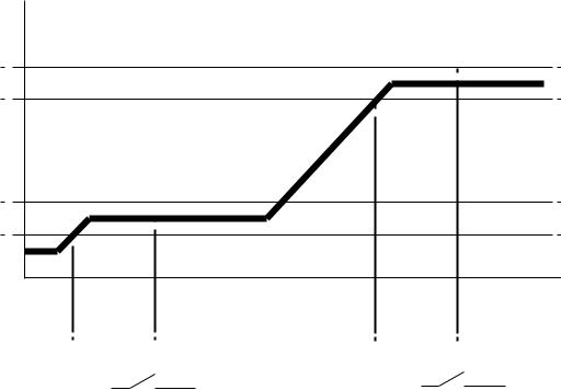
Latch Lock is a control mode available to any dimmer circuit (see Control:, page 20). Similar to switched mode, Latch-Lock features an additional safeguard so that circuits can not be turned on or off as easily. The circuit only turns on when a defined control level range is held for a specified amount of time, and only turns off when a different control level range is held for another amount of time. Latch-lock is useful for avoiding accidental dowsing of arc lamps during shows (often caused by running the Grandmaster down). By requiring a level range and time, most master fades will not hover in a given range for long enough to trigger on or off.
The level ranges and times can be edited on a per dimmer basis (see Dimmer Property Definitions, page 19). On and Off level ranges may not overlap.
Level
LatchLock Off Range
LatchLock On Range
Diagram of How Latch-Lock is Applied to a Circuit
Control Level |
|
In this range the control source can go |
Time |
|
to any level, as long as it does not stay |
|
|
in the off time range for more than the |
|
LatchLock On Time |
latchlock off time value |
LatchLock Off Time |
|
Relay Closes |
Relay Opens |
Lug
“Lug” refers to a physical position in the rack. Lugs are always numbered counting downwards from the top of the rack, starting at “1.” Some modules may take up multiple lug positions in the rack.
Panic
CEM3 offers a Panic capability that complies with UL 924 Panic functionality.
When a properly connected and enabled CEM3 has a panic “look” stored, when it receives a signal over the panic circuit it will automatically play the recorded look.
Panic can be enabled when a maintained (normally open or normally closed) contact closure is properly wired to the backplane (for more information, see the data termination guide or installation guide that was supplied with the rack).
For information on how to configure Panic on your CEM3, see Setting Up Panic, page 35.
12 |
CEM3 User Manual |

Patch
Patching governs the relationship between control input sources (DMX A, DMX B, and sACN) and the control of circuits in the rack. This relationship can be edited to match the needs of your control sources and rack constraints. For information on patching, see
Setting Up Patch, page 37.
Preset Functions
CEM3 supports a built-in preset control system allowing the recording and playback of preset looks. Preset looks can be played back either from the CEM3 face panel or using connected Echo preset stations. For more information on recording and playing back presets see Recording and Playing Back Presets, page 32.
CEM3 allows the circuits within the rack to be divided up into spaces (performed in Circuit Assignment, page 18) with 64 presets available per space. Each space can only have one active preset at a time.
CEM3 includes default presets that include all circuits in the space. The default presets for any space start with 100% and then cycle through 75%, 50%, 25%, 100% and so on.
Sensor3’s built-in EchoConnect power supply is limited to powering six racks or panels and six stations. An additional wall mounted or rack mounted power supply can be added to a system to support up to sixteen hosts and sixteen stations
C A U T I O N : |
Do not activate “Station power” on more than one CEM3 on the same |
|
EchoConnect bus. Doing so may cause undesirable station function. |
|
|
Preset activation propagates across the Net3 network. So if a given preset is activated for Space 1, all CEM3s on the network will activate that preset for space 1.
Rig Check
In Sensor3 racks with Advanced Features (see Advanced Features (AF), page 10) you can record a special preset called “Rig Check” which includes both circuit levels and the amount of load (current) expected on each circuit.
Once recorded, the rig check can be played back, either from the CEM3 face panel or remotely, and the CEM3 will post load high, load low, or no load messages based on how the load of the circuit has changed since you recorded the rig check preset. These messages will be available on the CEM3 display or on a connected console that monitors AF feedback.
Recording, running, and clearing a rig check can be performed from the Test menu (See “Test” on page 17.)
|
|
|
2 |
System Reference |
13 |

System Topology
EchoConnect - Belden 8471 + (1) 14 AWG ESD Ground Wire
External Power
Supply
Facilitates up to 16 racks and 16 stations
EchoConnect - Belden 8471 + (1) 14 AWG ESD Ground Wire
14 |
CEM3 User Manual |
Spaces
Spaces are logical divisions within a system (such as different rooms) that isolate station control (preset and sequence control) to the defined group of controllable outputs in that division. CEM3 supports separation of its controllable circuits into spaces.
Station Functions
Presets can be played back from preset stations in the system.
•Press a preset station button to activate a preset.
•Press it again to deactivate the preset.
•Stations can be configured with an “Off” button. This option is performed at the station and should only be done by a qualified technician.
•The group of presets controlled by any station can be altered at the station. This should only be done by a qualified technician.
For more information see the Echo Preset Station Installation Guide available from the ETC web site.
Zones
A space can be broken down further into zones. You can assign zone control to a preset station for direct control using that station’s buttons and fader knob. Multiple zones can exist within a space and a single zone can control multiple outputs across multiple racks.
A circuit’s control zone is a dimmer property and is assigned by accessing the dimmer setup menu (see “Arch Zone:” in Dimmer Property Definitions, page 19).
Each space can have up to 16 zones assigned (numbered 1-16).You can omit a circuit from zone control by setting the Arch Zone value to zero.
Redundant Tracking (ESR and FDX racks only)
Redundant tracking provides extra security in the event of system failure, allowing a secondary CEM3 control module to immediately take control of the rack.
Redundant tracking is available in ESR and FDX racks only.
For more information, see Redundant Tracking Systems, page 51.
|
|
|
2 |
System Reference |
15 |
Straight (rack numbering)
Straight rack numbering assigns consecutive dimmer numbering vertically, from top of the rack to the bottom, regardless of phasing.
This table compares the circuit numbering of an SR3-6 filled with D20 modules when set to straight or balanced numbering:
Rack |
SR3-6 |
SR3-6 |
|
Straight Circuit |
Balanced Circuit |
||
Phase |
Numbering |
Numbering |
|
|
1 |
1 |
|
A |
2 |
2 |
|
3 |
7 |
||
|
|||
|
4 |
8 |
|
|
5 |
3 |
|
B |
6 |
4 |
|
7 |
9 |
||
|
|||
|
8 |
10 |
|
|
9 |
5 |
|
C |
10 |
6 |
|
11 |
11 |
||
|
|||
|
12 |
12 |
Racks can be set to straight through Performing a Quick Setup, page 7.
16 |
CEM3 User Manual |

Menu Structure
This section lays out the entire menu structure for the software. Press the desired button to access the menu items below. Use the standard navigation method to select and enter options in the menus (see Navigation, page 6).
Test
Set Levels
Set levels for all circuits in a space.
Dimmer Check
Quickly run through all circuits in a space to test their output at a given percentage.
Release Set Levels
Release any active levels for a given space at once.
Presets
Record or play back presets. See Recording and Playing Back Presets, page 32.
Record Rig Check
Records a rig check preset to facilitate AF reporting. See Rig Check, page 13 and
Advanced Features (AF), page 10 for more information.
Run Rig Check
Runs a rig check preset. You will be notified of any load inconsistencies found during the rig check.
Clear Rig Check
Clears the recorded rig check from the CEM3.
About
Dimmers
View all properties for any circuit in a space. See Dimmer Property Definitions, page 19.
Rack
View all properties for the host Sensor rack. See Rack Property Definitions, page 22.
Errors
View any current errors or other status messages. See Error Messages, page 47.
Source Info
View the current control source (Highest-Takes-Precedence or “HTP”) and related output level being received by all circuits in a space.
About CEM3
Download a PDF of the CEM3 User Manual to a connected USB drive.
|
|
|
2 |
System Reference |
17 |
Loading...