


 Loading...
ColorSource AV Console
User Manual
Version2.6.0
PartNumber: 7225M1210-2.6.0Rev: A
Released: 2019-04
Toview a listoftrademarks andpatents, goto etcconnect.com/ip.
All othertrademarks, bothmarkedandnotmarked, are the property oftheirrespective owners. ETC intends this document, whetherprintedorelectronic, tobe providedinits entirety.

TableofContents
Introduction |
1 |
ColorSource 20 |
1 |
ColorSource 40 |
1 |
Shutdown |
1 |
UsingThis Manual |
1 |
Helpfrom ETC Technical Services |
2 |
RegisterYourDevice |
3 |
Online UserForums |
3 |
ColorSource Overview |
5 |
Touchscreen Performance |
5 |
Stage Map |
5 |
LayoutMode |
6 |
FaderMode |
7 |
Bumps |
7 |
Crossfader |
7 |
MasterFaders |
7 |
Getting Started With Patching |
9 |
Patch |
9 |
AddDimmer |
10 |
Duplicate Cell |
10 |
AddDevice |
11 |
Loadinga Fixture Profile |
12 |
Remove |
12 |
Show Universes / Show Stage Map |
12 |
InvertPan |
13 |
InvertTilt |
13 |
SwapPanandTilt |
14 |
RDM |
14 |
Identify |
14 |
AboutRDM |
15 |
Controlling Your Lighting System |
17 |
Channels |
17 |
Controls |
18 |
Quick Select |
18 |
Wheel |
19 |
Keypad |
19 |
Controlling Parameters |
20 |
Parameter |
20 |
How toProgram a ColorChip. |
25 |
Recording Your Looks For Playback |
29 |
Record/ Edit |
29 |
Playbacks |
30 |
RecordCue |
32 |
RecordSequence |
37 |
Operation |
40 |
GO |
42 |
Pause |
42 |
Back |
42 |
Undo |
42 |
Using Effects |
45 |
Effects |
45 |

Effect, Color |
46 |
Effect, Shape |
46 |
Effect, Intensity |
47 |
Effect, Parameter |
48 |
AddEffect |
49 |
Remove Effect |
50 |
Turning Lights Off |
51 |
Clear |
51 |
Blackout |
52 |
Special Functions |
53 |
Independent |
53 |
Playback Toy |
53 |
AV Functions |
59 |
Use ofMedia |
59 |
Media |
59 |
InputType |
61 |
OutputType |
61 |
AudioInputTips |
61 |
AudioOutputTips |
61 |
Preventing hum |
61 |
Image Controls |
62 |
VideoToy Controls |
63 |
Amigo® Remote WebBrowser |
64 |
OSC Commands |
68 |
System Settings and Setup |
71 |
Setup |
71 |
Settings |
71 |
Settings: General |
71 |
Settings: Times |
72 |
Settings: Independents |
72 |
Settings: Console |
73 |
Settings: Network |
74 |
Settings: Erase |
75 |
Showfile Management |
77 |
Files |
77 |
Files, Media |
80 |
Files, Advanced |
82 |
EULA |
84 |

Introduction
Welcome tothe ColorSource AV Console UserManual.
ColorSource 20
ColorSource 40
The topics foundinthis usermanual canalsobe foundonyourconsole by pressingthe  button. Tutorial videos are alsoavailable onyourconsole.
Shutdown
Holdthe StageMap button(left-mostbuttonbelow the screen) forthree seconds toselectthe Shutdown screen.
Shutdown sends the console intohibernation mode andturns offthe screenandindicators.
Toawakenthe console, press the now blue Stage Mapbuttonagain.
Note: Wheninhibernation mode, the console andits external powersupply unitstill consume some power. Toensure zeropowerconsumption, the external powersupply shouldbe disconnected from the AC mains supply.
Caution: All data is storedinternally innon-volatile memory. Donotswitchoffthe poweruntil any pending save operation is completed, oryoumay lose data. Itis strongly advisedthatyoumake periodic backups ofimportantdata toanexternal memory stick usingthe export function.
Itis recommended topowerthe unitonandoffonthe AC side ofthe external powersupply.
Using This Manual
This manual is foruse withColorSource AV Console.
Introduction |
1 |
Inordertobe specific aboutwhere features andcommands are found, the following namingandtextconventions will be used:
 Buttons, Browsermenus, andcommands are indicated in boldtext. Forexample: Inthe File menu, click Open.
 Alphanumeric keyboard buttons are indicated inall CAPS. Forexample, ALT orCTRL.
 References tootherparts ofthe manual are indicated inunderlined blue (forexample, Patch). When viewingthis manual electronically, click onthe reference tojumptothatsectionofthe manual.
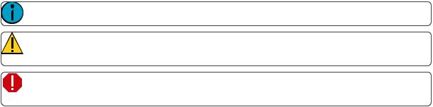
Note: Notes are helpful hints andinformation thatis supplemental tothe maintext.
Caution: A Cautionstatementindicates situations where there may be undefined orunwanted consequences ofanaction, potential fordata loss oranequipmentproblem.
 Warning: A Warningstatementindicates situations where damage may occur, people may be harmed, orthere are serious ordangerous consequences ofanaction.
Please email comments aboutthis manual to:TechComm@etcconnect.com
Help from ETC Technical Services
Ifyouare havingdifficulties, yourmostconvenientresources are the references giveninthis usermanual. To searchmore widely, try the ETC website at etcconnect.com. Ifnone ofthese resources is sufficient, contact ETC Technical Services directly atone ofthe offices identified below. Emergency service is available from all ETC offices outside ofnormal business hours.
Whencallingforassistance, please have the following information handy:
 Model andserial number(locatedonback panel)
 Facility name
 Othercomponents inyoursystem ( othercontrol devices, LED fixture types, etc.)
Americas |
UnitedKingdom |
ETC,Inc. |
Electronic TheatreControlsLtd. |
TechnicalServicesDepartment |
TechnicalServicesDepartment |
3031Pleasant ViewRoad |
26-28VictoriaIndustrialEstate |
Middleton,WI53562 |
VictoriaRoad, |
800-775-4382(USA,toll-free) |
LondonW36UUEngland |
+1-608831-4116 |
+44(0)2088961000 |
service@etcconnect.com |
techservltd@etcconnect.com |
Asia |
Germany |
Electronic TheatreControlsAsia,Ltd. |
Electronic TheatreControlsGmbH |
TechnicalServicesDepartment |
TechnicalServicesDepartment |
Room 1801,18/F |
Ohmstrasse3 |
Tower 1,Phase1EnterpriseSquare |
83607Holzkirchen,Germany |
9SheungYuet Road |
+49(8024)4700-0 |
KowloonBay,Kowloon,HongKong |
techserv-hoki@etcconnect.com |
+85227991220 |
|
service@etcasia.com |
|
2 |
Introduction |
Register Your Device
Registering yourdevice withETC ensures thatyouwill be notifiedofsoftware andlibrary updates, as well as any productadvisories.
Toregisteryourdevice, youwill needtoenroll in“My ETC,”a personalized ETC website thatprovides a more directpathofcommunication betweenyouandETC.
Registernow at http://www.etcconnect.com/product.registration.aspx.
Online User Forums
Youare encouraged tovisitandparticipate inthe ETC UserForum, accessible from the ETC website (etcconnect.com). This gives youaccess toanonline community ofusers where youcanreadaboutotherusers’ experiences, suggestions, andquestions regarding the productas well as submityourown.
Toregisterforthe ETC UserForum:
1.GotoETC’s community website (community.etcconnect.com).
2.Youmay registerforthe forum by clickingthe “join”link inthe upperrightcornerofthe page.
3.Follow the registration instructions providedby the community page.
Introduction |
3 |
4 |
Introduction |

ColorSource Overview
The ColorSource console is made upoffourdifferentphysical areas; the touchscreen (stage map), the faders andbumps, the crossfader, andthe masterfaders. Itis importanttofamiliarize yourselfwiththese different areas as youlearntouse yourconsole.
Touchscreen Performance
The ColorSource console touchscreen requires thatthe powersupply is grounded (witha three-pinconnector) foroptimal performance. Lack ofa grounded connection cancause the touchscreen tooperate erratically or notatall. This mightbe seenas unwanted operations orinability toprecisely selectanitem.
Ifnoearthed/ grounded outletis available, orifthe console is beingrunfrom anindependentpowersource, includingfrom a vehicle orbattery, itis possible thatthe touchscreen will notoperate correctly. Inthese situations itis advisedtodirectly connectyourbody tothe console chassis. This may be achievedwitha conductive wriststrap, ofthe kindusedinelectronics manufacturing orhospitals toeliminate static charge build-up. The cable ofthe strapshouldbe attachedtoa metallic partofthe console, forexample a screw orconnectoronthe rearpanel. Ifthis is notpractical, thenyoushouldatleastensure thatyoutouchthe console enclosure, the metallic partofit, withyourwristoryourotherhand.
Stage Map
The StageMap button(left-mostbuttonbelow the screen) displays a topographical mapof channels fullscreen atmaximum size. Youmay selectchannels onthe topographical stage mapforcontrol.
ColorSourceOverview |
5 |

Note: The StageMap buttonwill toggle betweendisplaying the Stage Maporthe previously selecteddisplay.
Available Controls
 Pinchtwofingers tozoom the display inorout, oruse the Zoombuttonlocatedby Clear. Zoom into see intensity levels withinthe channel cells.
 Dragwithtwofingers topanthe display.
 Single click ona deselected lighttoselectit.
 Single click ona selectedlighttodeselectit.
 Double click ona lighttoselectthatlightalone andde-selectall others.
 Use LayoutMode forstage mapcustomization.
  Selectedlights are indicated surrounded by a greenbox.
The vertical striptothe rightofthe mainarea displays special contentthatis playing:
 Effects: press anicontoStoporEditthe effect from playback. Press the icontoplace the effectonthe wheel controllertoincrease orreduce the effect.
 Audio(ColorSourceAVonly): press anicontoStoporEditthe audio from playback. Pick the iconto place the audiovolume onthe wheel controllertoincrease orreduce the volume ofthataudioclip.
 Video(ColorSourceAVonly): press anicontoStoporEditthe video from playback. Pick the iconto place the videoluminance onthe wheel controllertoincrease orreduce the videobrightness.
Note: The Effects, Audio, andVideoicons will only display ifthattype ofcontentis playing.
Layout Mode
Press andholda cell onthe stage map, orgoto Setup>LayoutMode toopenthe layoutscreen.
Wheninlayoutmode, the screendisplays as a grid. Press anddraglights tomove them toanotherpositionon the grid.
6 |
ColorSourceOverview |
Press the StageMap button(left-mostbuttonbelow the screen) toexitthe layoutmode.
Fader Mode
The faders tothe leftofthe display may be settooperate individual channels or playbacks.
Twopages ofchannels are providedandtenpages ofplaybacks.
Note: See channels forinformation onfaders andcapturedchannels.
Bumps
The buttons below the faders are bumpbuttons.
Theiroperation changes basedonthe fadermode.
 Whenthe faders are in channel mode, the bumps canbe usedtoselectordeselectchannels.
  Whenthe faders are in playback mode, theirbehavioris setbasedonthe selected buttonmode.
Crossfader
The Crossfadercanbe assignedtoone ofthe fourfaders above the touchscreen. Itis assignedinthe Console tab inSettings.
The Crossfaderprovides manual control overthe fades between cues. Youcansee the progress ofthe crossfade andwhichcues are affectedinthe cue viewer.
Master Faders
Masterfaders canbe usedtocontrol the outputofcertainfunctions. Masterfaders are the fourfaders above the touchscreen. They are assignedinthe Console tab inSettings.
ColorSourceOverview |
7 |

Note: Whenthe Playbacks orCues faders are fully downnooutputwill be produced by those sections.
Masterfaders defaulttothese functions:
 Volume(ColorSourceAVonly: controls the audiovolume.
 Playbacks: controls the outputofthe playbacks and sequences.
 Cues: controls the outputofthe cue list.
 Crossfader: Crossfades the cue listfrom the Live tothe Next step.
In Simple Mode
 Memory1- 4: The playback memories are the fourfaders above the touchscreen. Youmay record the outputandstore itonone ofthe fourmasters tobe re-usedlater.
8 |
ColorSourceOverview |

Getting Started With Patching
Tobe able tocontrol the lightingfixtures inyoursystem youneedtoassigneachfixture (ora groupofdimmers) toa channel fader. The channel fadercanthenbe usedtosetintensity ofa fixture. The channel alsobecomes a way toselectthatfixture forothertypes ofcontrol like colorchanges, oradjustmentofotherparameters (in the case ofa movinglight, forexample). The fixtures inyourlightingsystem are controlled usingthe DMX, streaming ACN, orArtNetprotocols, andeachdimmerorfixture uses a DMX address (orsetofaddresses) to communicate withthe console.
The Patch is usedtoassociate a channel withDMX addresses anddevice types. Once a channel is patchedto anaddress oraddresses, andthe outputis connected toa device (forexample a dimmer, movinglight, or accessory), the channel will thencontrol thatdevice.
Toaccess the Patchfunctions, press Setup>Patch.
Note: Ifyourpatchstays the same betweenshows, youcansave time by savinga defaultshow, whichwill loadyourpatchautomatically foryou.
Patch
Displays the patchingscreenandcontrols.
Patchingassociates a console channel numberwithanaddress orblock ofaddresses onthe DMX output. You mustensure thatthe address onthe light, dimmer, ordevice matches the address thatyousetupinPatch. To patcha basic device, press AddDimmer.
There are 5internal network universes thatcanbe assignedtoany sACN orArtNetuniverse numberin Setup>Settings>Network. Inthe Patchdisplay, the internal universe numberwill be displayed firstwiththe assigneduniverse inparentheses.
 Note: DMX always outputs onuniverses 1and2.
Complex devices withseveral parameters, suchas motion, color, orbeam controls, are described by a personality. Selectthe make andtype ofdevice tomatchthe actual connected device. Some devices have modes thatmustalsomatchonthe device andinthe patchlist. Lightingdevices with RDM available andenabledare foundautomatically andaddedtothe listofdevices. Youmuststill assignthem toconsole channel numbers though. Topatcha complex device thatis notautomatically foundby RDM, press AddDevice.
 Note: Custom fixture profiles canbe loaded. Please see Loadinga Fixture Profile forinstructions.
Duringpatchingyoumay addtags toeachlight, dimmer, ordevice toaidinconvenientgroupingonthe quick select screen.
GettingStartedWithPatching |
9 |

The lowersection ofthe screenmay be settodisplay the channel stage map ora view ofthe DMX universes output.
The settings andpatchforthe independents are onthe Ind. Tab in Settings.
Note: The media outputs, audioandvideo, donotneedtobe patchedas they are controlled directly.
Add Dimmer
Dimmers are single-address devices thatcontrol intensity only. Forpatchingmultiple-address devices, see Add Device.
Note: Dimmerpatchingcanalsobe usedtoconnectothersimple devices thatonly require one DMX address.
Patching a Dimmer or Single-address Device
1.Press Adddimmer.This will openthe PatchWizarddisplay.
2.Selectchannel toenterthe number.
3.Select Count toenterinthe numberofsimilardevices youare patching. Ifthe quantity is more than one, eachdimmerwill occupy one DMX address, startingfrom the address youspecify.
4.Select DMXtoenterthe DMX address (1through512).
5.Select Accept topatch, or Canceltoexit.
ForExample:
Ifyousetthe countto12andthe DMX address to20, the devices will occupy DMX addresses 20through31.
Patchingplaces the items ina listinthe upperpartofthe patch screenandonthe topographical stage map in the lowerpartofthe screeninrisingorderstartinginthe topleftcorner. Youmay selectone channel ata time inthe listoronthe stage map.
Eachchannel may be editedinthe boxes atthe topofthe screenforchannel number, DMX Universe and DMX address. Youmay alsoadd tags toeachitem sothatthey may be conveniently groupedonthe quick select screen.
Duplicate Cell
Duplicate cell lets youplace twodimmers onthe Stage Mapindifferentplaces patchedtothe same channel.
10 |
GettingStartedWithPatching |

Note: Duplicate cell adds dimmers only andnotdevices. Devices mustbe patchedandplacedindividually. See AddDevice.
Pick a channel inthe patchlistandselectthe + buttonandthenthe Duplicate cell buttontomake a copy.
A new cell is addedandis patchedtothe next-highestfree DMX address. Youmay change the address anduniverse andsettags in Patch.
Whena duplicate cell is selectedoroperated, eachofthe duplicate cells onthe Stage Mapwill respond together. Eachcell ofa duplicate channel may be movedseparately onthe Stage Map.
Note: Youcanalsoadddimmers toa channel withoutshowingthem as separate cells onthe Stage Map. Use AddDimmer andthensetthe channel numbertobe the same as the channel youwantto addthe dimmerto. Dimmers addedinthis way donotconsume space onthe Stage Map, for instance youmay needone channel tocontrol a range ofdimmers forhouse lights withoutwishing them tobe eachplacedandindicated separately.
Add Device
Devices are multiple-address lights witha numberofcontrollable parameters, suchas position, color, beam, andintensity. Devices have theirown personality, whichdefines whateachparameterdoes andwhichcontrols are needed.
Note: Lightingdevices with RDM available andenabledwill be foundautomatically andaddedto the listofdevices inthe patch. However, youmustassignthem toconsole channel numbers.
Patching a Device
1.Press AddDevice. This will openthe PatchWizarddisplay.
2.Selectthe correctpersonality from the listprovided. Selectthe make andtype ofdevice tomatchthe actual connected device. Some devices have modes thatmustalsomatchonthe device andinthe patchlist.
3.Selectchannel toenterthe number.
4.Select Count toenterinthe numberofsimilardevices youare patching. Ifthe quantity is more than one, eachdevice will occupy the numberofDMX addresses usedby its footprint, startingfrom the address youspecify.
5.Select DMXtoenterthe startingDMX address.
6.Enterthe desired Spacing.
7.Select Accept topatch, or Canceltoexit.
ForExample:
GettingStartedWithPatching |
11 |

Ifyoupatch12devices witha footprintof6DMX addresses eachtoaddress 20, they will occupy DMX addresses 20through91.
Topatchdevices witha gapbetweenthem, adjustthe Spacingvalue toa largernumber.
Note: Donotadjustthis toa smallernumberas thatwill cause overlaps andunexpected behavior from yourdevices.
ForExample:
Yourdevices use 17channels, butyouwouldprefertomanually address them atlogical startingnumbers like 1, 21, 41andsoon. Use the Spacingcell tochange the footprintto20sothatthose devices will automatically patchat1, 21, 41...
Patchingplaces the items ina listinthe upperpartofthe patchscreenandonthe topographical stage map in the lowerpartofthe screeninrisingorderstartinginthe topleftcorner. Youmay selectone channel ata time inthe listoronthe stage map.
Eachchannel may be editedinthe boxes atthe topofthe screenforchannel number, DMX Universe and DMX address. Youmay alsoadd tags toeachitem sothatthey may be conveniently groupedonthe quick select screen.
Note: Custom fixture profiles canbe loaded. Please see Loadinga Fixture Profile forinstructions.
Loading a Fixture Profile
Ifyouhave devices inyourlightingsystem thatcannotbe discovered by RDM andare notincludedinthe onboarddevice library, youcancreate yourownpersonality forthatdevice andimportitintoyourshow file. There is a device editorapplication forWindows PCs calledColorSource Personality Edit, whichis available for download atwww.etcconnect.com.
Torequesta fixture personality from ETC, please sendyourrequestalongwiththe usermanual, the required mode(s) andyourneedby date toColorSourceConsole@etcconnect.com.
Note: Forthe device torecognize the profile, the file name has tobe userlib.jlib.
1.Youwill needtosave the file ontothe rootdirectory ofa USBdrive tobe able toreaditfrom the device.
2.Withthe USBdrive pluggedintothe device, goto Setup>Patch>Add Device.
3.From the Source dropdown, selectUserLibrary. A new library will display withyourfixture listedby its manufacturer’s name.
Note: Custom device libraries are notstoredonthe device itself. Please store these custom files on yourUSBdrive oronanothercomputerforsafe keeping.
Remove
Selecta device ordimmer, andpress Remove toremove from the patch. Ifyouaccidentally remove a device ordimmer, youcanuse the Undo functiontorestore it.
The removeditem will nolongerdisplay onthe stage map.
Note: Ifyouhave recordeda device into playbacks or cues, andthenremove itfrom the patch, all the recordedvalues will remaininthe playback orcue, butthey will nolongerbe connected toa device.
Show Universes / Show Stage Map
12 |
GettingStartedWithPatching |

The lowersectionofthe Patch screenmay be settodisplay the topographical Stage Map ora chartofthe DMX addresses.
The DMX address chartis view-only andmay notbe edited. Scroll upanddowntoview all the addresses inthe selectedUniverse.
 Eachcell shows the DMX address, the value inthe range 0-255andthe name ofthe parameterfora device patchedwitha personality.
 Cells coloredin lightblue indicate the base address ofthe item, whichis the address enteredinthe PatchscreenDMX box. The following cells in dark blue show the following DMX addresses usedby the device according tothe size ofits footprint.
 Cells coloredin green indicate single dimmers.
 Cells coloredin red indicate patchingoverlap, where more thanone dimmerordevice is patchedtothe same DMX address. Insome cases itmay be desirable topatchwithoverlaps butusually itis a badidea tobe avoidedifpossible.
 A yellow bargraphindicates the approximate value beingoutput.
 Cells in black are unoccupied andnotpatched.
Invert Pan
Switches the pancontrol toruninthe opposite direction. Click onthe + buttoninpatchforthe device youwant toinvertpan.
Note: Use this ifyouhave riggeda lightupside-downorback-to-frontcompared toothersimilar lights sothatifthey are all selectedtogethertheirmovements will be insimilardirections.
Invert Tilt
Switches the tiltcontrol toruninthe opposite direction. Click onthe + buttoninpatchforthe device youwant toinverttilt.
Note: Use this ifyouhave riggeda lightupside-downorback-to-frontcompared toothersimilar lights sothatifthey are all selectedtogethertheirmovements will be insimilardirections.
GettingStartedWithPatching |
13 |

Swap Pan and Tilt
Exchanges panandtiltsothatpanonthe controls tiltonthe device andvice-versa. Click onthe + buttonin patchforthe device youwanttoswappanandtilt.
Note: Anexample ofwhentouse this functionwouldbe ifa fixture is hungsideways ora moving mirrorfixture is rotated90or270degrees from otherfixtures.
RDM
RDM is a two-way communications methodbuilt-intoordinary DMX512forlightingcontrol. See AboutRDM formore information.
The RDM buttonenables anddisables RDM onthe local DMX ports andRDM messages comingfrom gateways tothe console. Whenenabled, the RDM buttonwill be green. Ifyouhave problems withlights ordimmers connected tothe local ports onthe console thatflickerorsufferinterference whenyouopenthe patch screentry toturnoffthe RDM button.
Note: Whenyouexitthe patchscreen, all RDM messages are suppressed andonly ordinary DMX512is senttoyourlightingrigonthe local ports. The RDM buttonallows youtoturnoffRDM whenonthe patchscreen. Doingsowill preventthe patchscreenfrom findingandpatchingRDM lights. Youshouldonly suppress ifnecessary topreventflickerorerrors onthe local port(s) while you are inthe patchscreen.
Note: Youmay alsochoose toturnoffRDM whenyouhave patchedall the lights ina rigthatyou wishtouse. Ifthe rigcontains lights thatyoudonotwishtopatch, they will keepappearing inthe patchlist, awaitinga number, andyoucanpreventthis from beinganannoyance by turningoffthe RDM button.
RDMviaNetwork
RDM across a network connection from a ETC DMX/RDM Gateway tothe console may be enabledordisabled withthe RDM button.
Disabling RDM atthe console will notaffectwhatGateways doontheirrespective DMX outputs. RDM activity onthe DMX outputs ofGateways will dependonthe type andsetupofGateway beingused. Toenable ordisable RDM ona particularGateway DMX output, youshoulduse a network managementtool suchas ETC Net3Concert, orthe local controls ofthe Gateway itself.
Identify
Identifyfinds the RDM-capable lights duringpatchingsoitis easy toknow whichdevice is whichwhenassigningthem tochannels.
WhenRDM discovers a light, the lightis placedatthe topofthe patchlistwiththe channel shownas zero. When Identifyis settoOn, eachlightselectedinthe patchlistwill identify itselfexclusively, usually a lightwill blink onandoff. Devices thatdonotproduce light, forexample a scrollerorpan/tiltyoke, may shuffle ormove. The actionthata device does whentoldtoIdentify is determined by its manufacturer.
Youwill needtochoose a channel topatchthe device.
Note: Identify does notwork withnon-RDM devices ordimmers.
Turnoff Identifytostopall RDM Identification. Turnon Identifytosee the currently selectedRDM device.
14 |
GettingStartedWithPatching |

See Also: RDM
About RDM
RDM is a two-way communications methodbuilt-intoordinary DMX512forlightingcontrol. By usingRDM, youcanfindlights, findoutaboutthem andtheirstatus, patchthem, andsettheiroperating mode without needingtogotothe lightitself. Forlights riggedindifficultlocations, RDM is very useful forremote setup.
Discovery
RDM automatically discovers RDM-capable lights. Discovery runs continuously any time the Patchscreenis openandthe RDM button is enabled, andwill repeatedly searchfordevices. As devices are addedorremoved from a system, they will be updatedinthe patchlist.
Note: Discovery takes place duringshortperiods ofrestofnormal DMX transmission andis a lengthy process tocomplete. Youshouldexpectatleastseveral seconds ofdelay todiscovera light ona small system andmuchlongerdelays ona very large system.
Addressing and Mode
RDM allows youtosetthe DMX address andthe operating mode ofa lightremotely.
Settingthe operating mode may change the footprint, whichis the numberofDMX addresses occupiedby the device. Ifyouchange the mode ofa device adjacenttosome otherdevice ordimmers inpatch, the new mode couldbe largerthanthe available space andoverlapalready usedDMX addresses. Whenthis happens, the affectedones are indicated inthe patchlistinred, andyouwill needtotake corrective actionandre-patch.
The Patchsystem knows how tomatchthe chosenmode withthe correctpersonality.
Universe
Youcannotchange the Universe partofthe DMX patchfora Device foundby RDM. RDM canonly operate on the one universe itis connected to. Tochange the universe a lightis patchedto, youmustphysically re-plugthe lighttoanotherDMX cable.
GettingStartedWithPatching |
15 |
16 |
GettingStartedWithPatching |
Controlling Your Lighting System
Afteryouhave completed your patch, youare now ready tostartcontrolling yourlightingsystem. Your ColorSource console gives youmany options forcontrol ofyourlights.
This sectiondiscusses how tocontrol yourchannels, andhow tosetthe parameters.
Note: Depending onthe types oflights youhave patched, youmay have additional parameters thatyoucancontrol. Those parameters may include color, position (focus), beam, and lampcom- mands.
Channels
A channel is the control usedby the console tooperate a dimmer, a groupofdimmers, a dimmeranda device, ora complete movinglightfixture.
Channels needtobe associated withanaddress in patch forthere tobe output.
Channel Counts
 The ColorSource 20cancontrol upto20channels insimple mode, and40incomplete.
  The ColorSource 40cancontrol upto40channels insimple mode, and80incomplete.
Setting the Operating Mode
 Choose Simple or Complete mode onthe Setup>Settings>General screen.
Fader Pages
 Simple Mode offers one page offaders tocontrol the first20or40channels, depending onthe model.
 Complete Mode offers twopages offaders tocontrol all the available channels, 40or80depending on the model.
Working with Dimmers / Intensity
Channels canbe controlled inseveral differentways:
 The faders, whenin channel mode, canbe usedtocontrol a channel's intensity. Depending onthe chosenoperating mode: Complete or Simple, there are one ortwopages ofchannels thatthe faders cancontrol. In Complete Mode toggle the Channel buttontoaccess eachofthe pages.
Note: The secondpage ofchannels is only available whenchannels have beenpatchedon thatpage (above 21or41, depending onthe console model).
 Youcanuse the touchscreen andselectchannels directly onthe stage map. The wheel canthenbe usedtoassignanintensity level.
 Incomplete mode, youcanuse the keypad toselecta channel andassignanintensity level.
 Incomplete mode, channels canalsobe controlled by the playbacks, sequences, and cues. Insimple mode, channels canbe controlled by fourplaybacks.
Selected Channels
Tomake changes tochannel values, a channel mustbe selected. Selection is indicated by a thick greenborder aroundthe channel cell onthe Stage Mapanda litLED beneaththe channel fader. Selection canhappenina numberofways:
ControllingYour LightingSystem |
17 |
 Move a fadertoselecta channel. Ifthe channel is already ondue toplayback, move the faderuntil it matches the channel's currentoutput. Move the faderback tothe bottom "zero"positiontodeselectit (andtake its intensity tozero.)
 Touchthe channel cell onthe Stage Map. Touchthe cell againtodeselectit.
 Use the Keypadtotype inthe channel numbers andsetlevels.
  Todeselectall selectedchannels, use Clear>Selection.
Captured Channels
Selectedchannels thathave a manually setintensity level are considered "captured." This means thatthe selectedchannels' levels will be helduntil the channels are deselected orthe manual intensity values are cleared.
If Clear>Channelsis used, clearedmanual intensity values will returntothe levels comingfrom active playback sources immediately.
Ifmanually setchannels are simply deselected, manually setlevels will remainonstage until those channels geta new move instruction from a playback source.
Note: A channel fadermovedback tothe bottom (or"zero") positionwill deselectthatchannel. Youcannotholda channel atzerointensity usinga channel fader. Anotherselectionmethodmustbe used.
Controls
Controls containall the functions forcontrolling lights andcues, andsettingcolorandotherparameters:
Stage Map: The 'home' view ofthe full topographical stage map.
Param: Parametercontrol formovingorautomated lights.
Cue List: The cue display.
Playback Toy: A screentolaunchlightinglooks andplay, orbusk, live.
Keypad: Classic level control by typingnumbers.
Quick Select: Selection ofchannels inuseful blocks orsets.
Effects: Lightingeffects forcolor, intensity, andmovement.
Media: Audio, Video, Image, VideoToy, andSound2Lightcontrols.
Note: Paramis only available ifyouhave patchedlights withthose capabilities.
Quick Select
Inthe quick selectdisplay, youcanpick groups ofchannels according totheirpositiononthe topographical stage map orby choosingthe tags setupduringpatching.
18 |
ControllingYour LightingSystem |
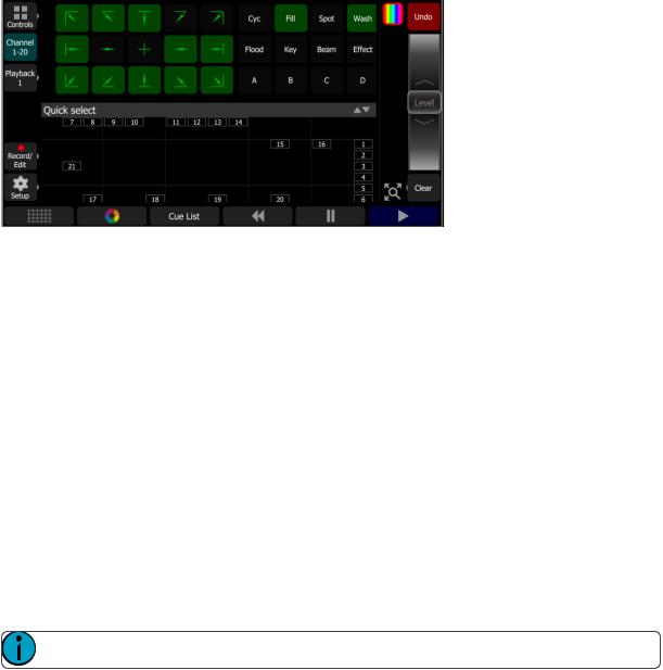
Groups display inthe uppersection, andthe lowersectionofthe screendisplays the channel stage map. Available groups are displayed ingreenboxes. Double click ona grouptoselectonly the lights inthatgroup, click onothergroups toaddorsubtractchannels from the selection.
While inthe quick selectdisplay, the wheel operates the level ofthe selectedchannels proportionally. The groupbuttons are alsovariable cells thatmay be wipedupanddowntoalterthe value.
Whenyouexitthe quick selectdisplay, the channels will remainselectedandcolors orotherparameters may be appliedtothem.
Wheel
Tothe rightofthe stage map is the wheel. The wheel canbe usedtocontrol channel levels by movingthe wheel uptoincrease the level ordowntodecrease.
The wheel canalsobe usedtocontrol depthof effects and sequence rate.
In Simple mode
Tothe rightofthe stage map is the wheel. The wheel canbe usedtocontrol channel levels by movingthe wheel uptoincrease the level ordowntodecrease.
Keypad
The keypadis openedby goingto Controls>Keypad. This provides classic lightingcontrol ofchannels and levels via a numeric keypadentry.
Note: Effects, Media, and Parameter settings mustbe controlled ontheirrespective screens.
Available Buttons
 + (Plus)
 - (Minus)
 Thru
Thru
 Full
Full
 @ (At)
 ..<<..(Backspace)
 Enter
Enter
ControllingYour LightingSystem |
19 |
Keypad, Plus
Adds a channel tothe selectionset.
ForExample:
1 Thru10 + 20 Enter - creates a setofelevenchannels: 1-10plus 20.
Keypad, Minus
Removes a channel from the selectionset.
ForExample:
1 Thru10 - 7 Enter - creates a setofnine channels: 1through6plus 8through10.
Keypad, Thru
Selects a range ofchannels.
ForExample:
1 Thru10 Enter - creates a setoftenchannels: 1through10.
Keypad, Full
Sets the selectedchannels tofull intensity.
Toapply the chosenintensity, youmustcomplete the command withthe Enter key.
ForExample:
1 @ FullEnter - sets channel one tofull intensity.
Keypad, @ (at level)
Sets the selectedchannels toa level specifiedinpercent% from 0to100.
Toapply the chosenintensity, youmustcomplete the command withthe Enter key.
ForExample:
1 + 5 @ 70 Enter - sets channels one andfive to70% intensity.
Keypad, <-- (Backspace)
The <-- key behaves as a backspace buttonforthe command line.
Controlling Parameters
Depending onthe types oflights youhave patched, youmay have additional parameters thatyoucancontrol. Those parameters may include color, position (focus), beam, and lampcommands.
Parameter
All the controllable features ofanautomated light, withthe exception ofthe intensity, are knownas the parameters ofthe light.
Parameters may include position(pan/tilt), colormix, beam control (iris, focus, etcetera), orlampcontrols. The tabs alongthe topallows viewingofall parameters oronly a selectedtype. Tabs withadditional pages display withanindicatorunderthe parametername. Tapona tabtwice toaccess page twoandthree times forpage three.
20 |
ControllingYour LightingSystem |
Eachcell onthe parameterdisplay is a controllable buttontoalterthe value. Press andholdonthe cell andyou canwipe the value upanddown, usingthe entire screenheightforcontrol.
Press once andrelease ona cell toreveal a filmstrip-style view ofthe available settings, withdiagrams ofgobos andsamples offixedcolors. The stripmay be scrolledleft-rightuntil the desiredsettingis found. Pick the settingtoclose the filmstrip.
Parameter, All
Shows all the available parameters.
Note: The Parambuttonis only presentifyouhave patchedlights withthose capabilities.
Controls the parameters ofthe selectedlight(s). Only lights withparameters may be controlled here.
Pick a parameterandswipe the value box upanddowntochange values. A greenarrow will appearonthe value box whenyouare swipingit.
Pick the value box withone press toopena filmstripview ofthe available settings.
ControllingYour LightingSystem |
21 |

The filmstripmay be scrolledleftorrighttosee all the choices.
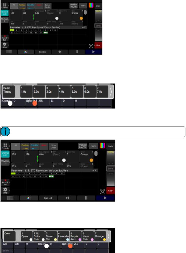
Parameter, Beam
Shows only the beam parameters. All parameters thatare notposition, intensity orcolormixingare includedin the beam parameterset.
Note: The Parambuttonis only presentifyouhave patchedlights withthose capabilities.
Controls the parameters ofthe selectedlight(s). Only lights withparameters may be controlled here.
Pick a parameterandswipe the value box upanddowntochange values.
Pick the value box withone press toopena filmstripview ofthe available settings. The filmstripmay be scrolledleftorrighttosee all the choices.
Parameter, Position
Show only the positionparameters, panandtilt. There are twopages ofpanandtiltcontrols. The firstpage displays value boxes forpanandtilt.
Note: The Parambuttonis only presentifyouhave patchedlights withthose capabilities.
Control the parameters ofthe selectedlight(s). Only lights withparameters may be controlled here.
Pick a parameterandwipe the value box upanddowntochange values.
22 |
ControllingYour LightingSystem |

Pick the value box withone press toopena filmstripview ofthe available settings. The filmstripmay be scrolledleftorrighttosee all the choices.
The secondpage displays a cross hairpanandtiltcontrol. Tapthe tabtwice togettothe secondpage.
A white dotis usedtoindicate the currentlocation. The actual panandtiltvalues will display above the Nudge button. Press anywhere withinthe crosshairs tomove yourdevice.
Forfine control ofpanandtilt, use the Nudge button. See Nudge formore information.
Parameter, ColorMix
Lights thathave a colormixingsystem may be operatedfrom this tab. There are twopages ofcolormixing tools andone page fordirectemittercontrol. The firstpage displays the colorpicker, andthe secondpage displays the colorchips. Tapthe tabtwice togettothe secondpage, andthree times togettothe directemitter page.
Note: The Parambuttonis only presentifyouhave patchedlights withthose capabilities.
Lights mustbe selectedbefore a colorchoice canbe appliedtothem. Selectsome lights onthe stage map view, orwiththe bumpbuttons ifthe fadermode is setto channels, andthenpick a colorortry several colors.
The colorpickeris a diagram ofthe visible spectrum varyingby hue from lefttorightandby saturation (paleness) from toptobottom. The colorpickercanbe settocolors orwhites mode. See Whites formore information.
A black dotis usedtoindicate the colorselected. Press Nudge toputthe colorpickerinfine mode. See Nudge formore information.
The secondpage displays the colorchips. Colorchips are a setofpresetcolorchips. Colorchips may be programmed tocarry any colormix. See SetupColorChips formore information.
ControllingYour LightingSystem |
23 |

Note: Notall colormixingsystems canproduce precise colormatches anda full range ofcolors. Itis advisable tocontrol colorononly one fixture type ata time.
Note: Youmay finditnecessary topick colors independently fordifferentlights inorderthatthey all produce a similarcolor.
The thirdpage is fordirectemittercontrol. Directemittercontrol provides anadditional methodofcolorcontrol thatallows forthe manipulation ofeachindividual LED emitter.
Whencolorvalues are setvia the colorpicker, theirvalues will display inparentheses whenviewedinthe directemitterpage.
Tochange anindividual emitter, pick a colorandwipe the value box upanddowntochange values.
Forlights withfixedranges ofpresetcolors, suchas colorwheels orscrollers, use the parameterall tab.
The filmstripmay be scrolledleftorrighttosee all the choices.
Whites
The colorpickercanbe settoeithercolors orwhites. Inwhites mode, the pickerwill attempttomatchthe shade ofwhite selected. However, the actual shade ofwhite produced will dependonthe type oflightandits capabilities.
Use the Nudge functiontogetthe desiredshade.
24 |
ControllingYour LightingSystem |
Loading...